What Are the Core Components of an Industrial Biomass Boiler?
In industrial operations, choosing biomass boilers as a renewable heating solution presents both opportunities and challenges. However, many users face performance issues, frequent maintenance, or inefficient combustion due to a lack of understanding of the boiler’s internal structure. Without a clear grasp of the core components and how they interact, buyers risk costly downtime, safety hazards, and low return on investment. The solution lies in understanding the fundamental components of an industrial biomass boiler to ensure correct selection, installation, and maintenance for long-term efficiency.
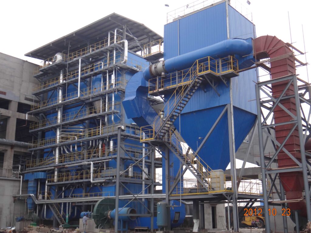
The core components of an industrial biomass boiler include the fuel feeding system, combustion chamber, heat exchanger, flue gas cleaning system, ash handling system, and the control unit. Each part plays a crucial role: the feeding system delivers biomass fuel, the combustion chamber ensures efficient burning, the heat exchanger transfers energy to the process system, while emissions and ash are managed by their respective systems. The control system integrates all operations to maintain optimal performance, safety, and automation.
To make informed decisions when selecting or operating a biomass boiler, it’s essential to understand the function and importance of each component. Keep reading to gain in-depth insights that can improve your plant’s thermal efficiency, reduce emissions, and prolong boiler life.
What is the Fuel Feeding System in an Industrial Biomass Boiler and How Does It Work?
Industrial biomass boilers rely on an efficient, automated, and continuous fuel feeding system to ensure uninterrupted operation and high combustion efficiency. But when the fuel feeding system is faulty or poorly designed, the consequences include inconsistent combustion, frequent downtime, energy loss, increased emissions, and even serious mechanical damage. For biomass boiler users—especially in sectors like paper manufacturing, food processing, and district heating—understanding the working principle and types of fuel feeding systems is crucial to ensure operational success. In this article, we’ll explore how biomass fuel feeding systems function, the components involved, and how to choose the right system for your needs.
A fuel feeding system in an industrial biomass boiler is a mechanical and automated mechanism that transports biomass fuel—such as wood chips, pellets, or agricultural waste—from a storage unit (like a silo or bunker) into the combustion chamber at a controlled rate. This system typically includes components such as storage hoppers, belt or screw conveyors, rotary valves, and feed chutes. The system ensures uniform fuel delivery, optimizes combustion efficiency, and minimizes manual handling.
Understanding the structure and function of the fuel feeding system gives you control over combustion stability and cost-efficiency. Whether you’re evaluating a new biomass plant or troubleshooting inconsistent heat generation, this article will guide you through essential technical details and system configurations.
Biomass boiler feeding systems require manual fuel loading.False
Modern biomass boiler feeding systems are fully automated, using conveyors, screw feeders, or hydraulic pushers for continuous, hands-free operation.
Key Components of Biomass Fuel Feeding Systems
Fuel feeding systems vary based on fuel type, boiler design, and plant capacity, but they typically include the following components:
| Component | Function |
|---|---|
| Fuel Storage Hopper | Temporary buffer to store fuel before feeding into boiler |
| Conveyor Belt | Transports biomass from main storage to hopper or directly to the feeder |
| Screw Feeder | Moves fuel in a controlled manner into the combustion chamber |
| Rotary Airlock Valve | Prevents air backflow and maintains pressure separation |
| Fuel Chute | Gravity-fed section guiding fuel to combustion zone |
Biomass materials differ in shape, size, moisture content, and density. These factors influence system selection. For example, wood pellets require different feed rates and handling systems than wet wood chips or sawdust. In many industrial boilers, redundancy is built in to ensure that even if one conveyor fails, fuel feeding can continue through an alternative path.
How the Biomass Fuel Feeding System Works: Step-by-Step
Let’s take a deep dive into the operational flow:
1. Fuel Reception and Primary Storage
Fuel arrives in bulk trucks or trailers and is dumped into a primary fuel pit or silo. From here, belt conveyors or chain conveyors move the biomass into an intermediate storage bunker.
2. Metering and Regulation
The stored fuel passes through a screw metering system. This regulates the flow to match the combustion demand. The variable frequency drive (VFD) motor attached to the screw conveyor enables precise control of the feed rate.
3. Airlock Valve System
To avoid pressure and gas leaks, a rotary airlock valve is used. It allows the solid biomass to pass while sealing gases inside the combustion chamber. It also prevents backflow of flames or high-pressure air.
4. Final Fuel Delivery
The fuel enters the fuel chute or burner throat, depending on whether it’s a moving grate boiler, fluidized bed, or fixed bed boiler. Sensors monitor the flow rate, temperature, and feed consistency. If a blockage or imbalance is detected, the control system adjusts motor speed or activates auxiliary feeding mechanisms.
Diagram: Fuel Feeding Workflow
| Stage | Component Involved | Key Parameter Controlled |
|---|---|---|
| Initial fuel intake | Receiving Pit, Belt Conveyor | Bulk volume |
| Intermediate buffering | Hopper or Bunker | Fuel availability |
| Controlled feeding | Screw Conveyor, VFD Motor | Feed rate (kg/h) |
| Air-sealing | Rotary Airlock Valve | Pressure control, backflow prevention |
| Final delivery | Fuel Chute, Feed Spreader | Distribution in combustion chamber |
Types of Biomass Fuel Feeding Systems
There are several configurations to suit different fuel properties and boiler types:
1. Screw Conveyor Systems
Ideal for granular fuels like pellets or dry chips. They are cost-effective, compact, and precise.
2. Hydraulic Pusher Feeding
Used for bulky, high-moisture fuels such as forest residues. They use a ram or piston to push material into the combustion area.
3. Chain Conveyor Systems
Robust and suitable for heavy, fibrous fuels. These can handle high throughput but require more maintenance.
Comparison Table of Feeding System Types
| Feeding System | Fuel Type Suitability | Maintenance Need | Cost | Precision | Typical Applications |
|---|---|---|---|---|---|
| Screw Conveyor | Pellets, chips, sawdust | Low | Medium | High | Small-to-medium plants |
| Hydraulic Pusher | Logs, wet biomass, bales | Medium | High | Medium | Large industrial boilers |
| Chain Conveyor | Agricultural residue, bark | High | High | Low | District heating, power stations |
Common Challenges and Solutions
Even with automation, feeding systems face several challenges:
- Blockages: Caused by fuel bridging or oversize particles. Solution: install vibration or agitation mechanisms.
- Wear and Tear: Screw conveyors erode over time. Solution: use abrasion-resistant steel.
- Inconsistent Feed Rate: Affects combustion stability. Solution: deploy real-time sensors and feedback loops.
Regular maintenance and smart system design—such as inclining the conveyor at optimal angles or integrating redundancy—can dramatically reduce downtime.
Energy Efficiency and Automation Integration
Modern systems are integrated with SCADA or PLC-based automation, enabling:
- Remote monitoring
- Real-time alarms
- Predictive maintenance alerts
- Adaptive feeding based on flue gas analysis or steam demand
Case Study: A 15 MW Biomass Boiler in Finland
An industrial paper mill in Finland uses a screw-based fuel feeding system for its 15 MW biomass boiler. It handles mixed biomass including bark and pellets. The feeding system is VFD-controlled and integrated with the mill’s energy management system. By optimizing feed rate according to real-time calorific value measurements, the system improved combustion efficiency by 12% and reduced manual intervention by 85%.
How Does the Combustion Chamber Ensure Efficient Biomass Fuel Burning in an Industrial Biomass Boiler?
-scaled.jpg)
Biomass fuel combustion can be highly efficient—but only when the combustion chamber is properly designed and controlled. If the combustion chamber is poorly engineered or improperly operated, biomass boilers suffer from low thermal efficiency, high emissions, incomplete combustion, excessive ash, and even equipment damage. This directly increases fuel consumption and operating costs. Fortunately, a well-designed combustion chamber ensures optimal fuel-air mixing, staged combustion, and sufficient residence time for complete burning. In this article, we delve deep into the science and engineering behind how the combustion chamber plays a crucial role in the efficiency of biomass boilers.
The combustion chamber in an industrial biomass boiler ensures efficient biomass fuel burning by providing a controlled environment that optimizes air-fuel mixing, maintains high combustion temperatures, and enables sufficient residence time for complete thermal decomposition and oxidation of the biomass. Features such as staged air supply, refractory lining, turbulence generation, and proper chamber sizing help achieve maximum heat release, low emissions, and high fuel utilization.
Understanding the combustion chamber is essential for operators, engineers, and procurement managers seeking performance reliability, energy efficiency, and environmental compliance in industrial biomass systems.
Biomass combustion chambers operate effectively without staged air supply.False
Staged air supply is essential in biomass combustion chambers to ensure complete combustion, reduce carbon monoxide, and control nitrogen oxide emissions.
The combustion chamber acts as the core of biomass boiler functionality. Unlike fossil fuel combustion, biomass combustion involves several phases—including drying, devolatilization, char oxidation, and ash formation. The chamber must be designed to accommodate all these processes effectively.
Phases of Biomass Combustion in the Chamber
| Combustion Phase | Temperature Range (°C) | Key Reaction | Chamber Requirement |
|---|---|---|---|
| Drying | 100–200 | Evaporation of moisture | Preheating zone with low turbulence |
| Devolatilization | 200–600 | Release of volatile gases | High turbulence and oxygen availability |
| Volatile Combustion | 600–1200 | Combustion of released gases | Adequate secondary air injection |
| Char Combustion | 800–1100 | Oxidation of carbon-rich residues | Long residence time and consistent heat |
| Ash Formation | >1100 | Mineral residue discharge | Grate/ash handling zone |
Critical Design Features for Efficient Biomass Combustion
1. Refractory Lining and Insulation
- Maintains high temperatures (>850°C)
- Protects chamber walls from corrosive elements
- Increases heat retention and uniformity
2. Staged Air Supply
- Primary Air: Injected below the grate or fuel bed to support drying and devolatilization.
- Secondary Air: Injected above the fuel bed to aid in burning volatiles and reduce CO/NOx.
- Tertiary Air (if applicable): Enhances mixing and combustion of residual gases.
Air Supply Optimization Table
| Air Type | Injection Zone | Purpose | Typical Volume % of Total Air |
|---|---|---|---|
| Primary Air | Under the grate | Ignite solid fuel, support drying | 30–50% |
| Secondary Air | Above fuel bed | Burn volatiles, reduce CO/NOx | 40–60% |
| Tertiary Air | Upper chamber zones | Final cleanup, turbulence | 0–10% |
3. Turbulence and Mixing
- Critical for complete combustion
- Achieved through chamber geometry, air jet design, and fuel injection patterns
- Enhances air-fuel contact and flame stability
4. Residence Time
- Biomass gases require 1.5 to 3 seconds at >850°C for complete combustion
- Chamber length and flow dynamics are designed to allow this time before flue gas exits
5. Fuel Bed Management and Grate Systems
- Moving grates, fixed grates, or fluidized beds distribute fuel evenly
- Ensure complete burnout of char and ash removal
Real Example: Moving Grate Combustion Chamber
A moving grate system, often found in 5–50 MW industrial biomass plants, continuously transports biomass across multiple temperature zones:
| Zone | Function | Temperature |
|---|---|---|
| Drying Zone | Moisture evaporation | 100–200°C |
| Pyrolysis Zone | Volatile gas release | 300–600°C |
| Combustion Zone | Flame development, oxidation | 800–1200°C |
| Burn-out Zone | Char and ash oxidation | >1000°C |
Proper grate speed and air control in each zone directly influence combustion efficiency.
Combustion Efficiency Monitoring
Sensors and control systems monitor:
- Flue gas O₂ and CO levels
- Flame temperature
- Grate temperature
- Boiler outlet temperature
These inputs are used to adjust:
- Fuel feed rate
- Air-to-fuel ratio
- Grate movement speed
Example: Combustion Efficiency Graph Based on Air Supply Ratio
| Air-Fuel Ratio | Combustion Efficiency (%) |
|---|---|
| 1.0 | 75% |
| 1.5 | 85% |
| 2.0 | 92% |
| 2.5 (excess air) | 88% |
Too little air = incomplete combustion (CO, smoke)
Too much air = heat loss via excess flue gas
Advanced Combustion Chamber Innovations
- Low-NOx Burners: Reduce emissions by controlling temperature peaks and oxygen zones.
- Recirculated Flue Gas Injection: Reintroduces cooled flue gases to stabilize flame and reduce NOx.
- Ceramic and Swirl Flame Stabilizers: Improve flame structure and combustion uniformity.
Case Study: Combustion Optimization in a 20 MW Biomass Boiler in Germany
A German plant switched from a fixed grate to a moving grate chamber with staged air injection. Key results:
- Combustion efficiency increased from 84% to 93%
- Particulate emissions reduced by 40%
- Unburned carbon in ash dropped by 50%
- Fuel savings of 7% annually
What Role Does the Heat Exchanger Play in an Industrial Biomass Boiler System?
In industrial biomass boiler systems, the conversion of fuel into usable thermal energy doesn’t stop at combustion. Even with perfect combustion, if heat cannot be captured and transferred efficiently, the system fails to deliver energy cost-effectively. This is where the heat exchanger becomes critical. Without it, most of the energy from burning biomass would be lost with the flue gases, resulting in inefficiency, higher fuel consumption, and environmental non-compliance. Fortunately, a well-designed heat exchanger ensures efficient energy recovery, fuel cost savings, and emissions control. In this article, we reveal the exact function, design, and operation of the heat exchanger in biomass boiler systems—and why it’s the unsung hero of thermal performance.
The heat exchanger in an industrial biomass boiler system plays a vital role in transferring thermal energy from hot flue gases produced during biomass combustion to a working fluid such as water or steam. This process allows the boiler to convert combustion heat into usable thermal energy for heating, power generation, or industrial processes. Efficient heat exchangers maximize energy recovery, reduce fuel consumption, and minimize flue gas heat losses, directly improving boiler efficiency and sustainability.
By understanding the internal function and structure of the heat exchanger, operators and engineers can ensure their biomass systems operate at peak thermal performance and regulatory compliance.
Heat exchangers in biomass boilers are optional and do not significantly affect efficiency.False
Heat exchangers are essential in biomass boilers, as they enable effective energy transfer from combustion gases to water or steam, significantly impacting overall system efficiency.
How the Heat Exchanger Works in Biomass Boilers
The heat exchanger operates on a simple principle: heat transfer between two media without direct contact. In the case of biomass boilers, the two media are:
- Hot flue gases (from the combustion of biomass)
- Water or steam (in the boiler system)
Primary Function:
- Recover heat from flue gases (~800–1000°C)
- Transfer it to the boiler’s water/steam system (typically raising it to 150–350°C)
- Maintain temperature differential for continuous flow and energy production
Heat Exchanger Types in Biomass Boilers
| Type | Description | Use Case |
|---|---|---|
| Shell and Tube | Tubes carrying water are surrounded by hot flue gas | Large-scale boilers |
| Fire-tube | Hot flue gases pass through tubes submerged in water | Medium-capacity boilers |
| Water-tube | Water circulates in tubes heated externally by hot gases | High-pressure steam applications |
| Economizer | Preheats feedwater using flue gas heat | Increases overall system efficiency |
| Air Preheater | Transfers heat from flue gas to incoming combustion air | Enhances combustion and saves fuel |
Internal Structure of a Biomass Boiler Heat Exchanger
Heat Transfer Zones:
| Zone | Function | Typical Temp Range (°C) |
|---|---|---|
| Superheater | Raises steam temperature post-saturation | 450–550 |
| Evaporator/Boiler Bank | Converts water into saturated steam | 200–350 |
| Economizer | Preheats feedwater using low-temperature flue gases | 100–180 |
Flow Arrangement:
- Counter-flow or cross-flow maximizes thermal gradient and transfer efficiency
- Baffles direct flue gas across tube bundles to increase heat transfer surface area
Material Selection:
- Heat-resistant alloys like stainless steel (304/316) or carbon steel are common
- Ash- and corrosion-resistant coatings are used in areas with aggressive gases or high ash content
Heat Exchanger Efficiency Metrics
| Parameter | Typical Value | Impact on System |
|---|---|---|
| Heat Transfer Efficiency | 75–92% | Higher values reduce fuel usage |
| Flue Gas Outlet Temperature | <180°C | Indicates better energy capture and less heat loss |
| ΔT between fluids | 50–150°C | Wider ΔT enables greater heat transfer |
| Surface Fouling Factor | <0.001 m²·K/W | Affects maintenance and cleaning needs |
Technical Chart: Effect of Flue Gas Temperature on Boiler Efficiency
| Flue Gas Temp (°C) | Boiler Thermal Efficiency (%) |
|---|---|
| 250 | 75% |
| 200 | 80% |
| 150 | 87% |
| 120 | 90% |
Lower flue gas temperature = higher boiler efficiency
Maintenance and Fouling Considerations
Biomass combustion generates ash and particulates that can deposit on heat exchanger surfaces. If not managed, this leads to:
- Reduced heat transfer
- Higher flue gas temperature
- Increased fuel consumption
Preventive Measures Include:
- Soot blowers and ash rapping systems
- Water or air-based cleaning lances
- Material coatings for anti-fouling
- Access doors for manual inspection
Common Maintenance Intervals
| Component | Cleaning Interval | Inspection Frequency |
|---|---|---|
| Tube Bundles | Every 2–4 weeks | Monthly |
| Economizer Coils | Every 3 months | Quarterly |
| Air Preheater | Semi-annually | Annually |
Case Study: Biomass Power Plant in Austria (25 MW)
The plant installed a shell-and-tube economizer after its main heat exchanger. Result:
- Boiler efficiency rose from 82% to 91%
- Flue gas temperature dropped from 220°C to 130°C
- Annual fuel savings of 9%
- Payback period of 14 months on economizer investment
Integration with Other Boiler Systems
- Boiler Control System: Adjusts feedwater and combustion based on heat exchanger output
- Steam Drum: Collects and distributes generated steam
- Flue Gas Treatment: After heat exchange, gases are cooled and treated for emissions
Advanced systems also use real-time monitoring sensors to track heat exchanger performance:
- Inlet/outlet fluid temperatures
- Pressure drop across heat exchanger
- Steam quality sensors
- Ash buildup detectors
How Does the Flue Gas Cleaning System Improve Environmental Compliance in Industrial Biomass Boilers?
Industrial biomass boilers are known for their sustainability, but without proper flue gas cleaning, they can emit significant amounts of particulate matter (PM), nitrogen oxides (NOx), sulfur oxides (SOx), volatile organic compounds (VOCs), and heavy metals. These emissions not only harm air quality but also lead to regulatory violations, fines, and operational shutdowns. A properly designed flue gas cleaning system ensures compliance with environmental regulations such as the EU Industrial Emissions Directive (IED), U.S. EPA Clean Air Act, and global ISO emissions standards. In this article, we explore how flue gas cleaning systems work, their types, and their role in making biomass energy both efficient and environmentally responsible.
A flue gas cleaning system in an industrial biomass boiler improves environmental compliance by capturing and neutralizing harmful emissions such as particulate matter (PM), nitrogen oxides (NOx), sulfur oxides (SOx), and dioxins before they are released into the atmosphere. This is achieved through a combination of mechanical filtration, electrostatic precipitation, wet scrubbing, and catalytic conversion technologies that ensure emissions remain within regulatory limits, reducing air pollution and meeting environmental standards.
By understanding these systems, biomass plant operators can reduce emissions, improve efficiency, and maintain regulatory approval while ensuring sustainable energy production.
Biomass boilers do not require flue gas cleaning for environmental compliance.False
Most environmental regulations require industrial biomass boilers to install flue gas cleaning systems to control emissions of particulates, NOx, SOx, and other pollutants.
Major Pollutants in Biomass Boiler Flue Gas and Their Environmental Impact
| Pollutant | Main Source in Biomass Combustion | Environmental Impact | Regulatory Limit (Typical) |
|---|---|---|---|
| Particulate Matter (PM) | Unburned carbon, ash, soot | Causes respiratory diseases, air pollution | < 20 mg/Nm³ |
| Nitrogen Oxides (NOx) | High-temperature combustion of nitrogen in air | Forms smog, acid rain, respiratory issues | < 200 mg/Nm³ |
| Sulfur Oxides (SOx) | Sulfur content in biomass (e.g., bark) | Contributes to acid rain, corrosion | < 100 mg/Nm³ |
| Carbon Monoxide (CO) | Incomplete combustion | Toxic gas, affects air quality | < 100 mg/Nm³ |
| Dioxins & Furans | Poor combustion control, chlorine in fuel | Carcinogenic, persistent organic pollutants | < 0.1 ng/Nm³ |
| Heavy Metals (Hg, Pb) | Impurities in biomass fuel | Toxic accumulation in ecosystems | < 0.05 mg/Nm³ |
To meet these limits, industrial biomass boilers deploy multi-stage flue gas cleaning systems that combine different technologies.
Key Components of a Flue Gas Cleaning System
The system typically consists of multiple stages to remove different pollutants:
| Component | Function | Pollutants Removed |
|---|---|---|
| Cyclone Separator | Uses centrifugal force to remove large dust particles | Particulates (>10 µm) |
| Baghouse Filter | Fabric filters trap fine dust and ash | PM10, PM2.5 |
| Electrostatic Precipitator (ESP) | Charges particles electrically and collects them on plates | Fine PM, heavy metals |
| Scrubber (Wet/Dry) | Chemical absorption of SOx, acid gases | SOx, HCl, HF |
| Selective Catalytic Reduction (SCR) | Converts NOx into harmless nitrogen and water | NOx |
| Activated Carbon Injection | Adsorbs dioxins, furans, and mercury | Dioxins, VOCs, heavy metals |
How the Flue Gas Cleaning Process Works: Step-by-Step
- Initial Dust Separation – Cyclone Separator
- Removes large ash particles using centrifugal force
- Reduces load on downstream filters, improving efficiency
- Fine Particle Filtration – Baghouse Filter or ESP
- Baghouse Filter: Uses fabric filter bags to capture PM2.5 and soot
- ESP: Uses electric fields to charge and collect fine particles
- Gas Cleaning – Scrubber & Activated Carbon Injection
- Dry Scrubbers: Inject alkaline substances (lime, sodium bicarbonate) to neutralize SOx
- Wet Scrubbers: Spray water or chemicals to absorb acidic gases
- Activated Carbon Injection: Captures dioxins and mercury
- NOx Reduction – Selective Catalytic Reduction (SCR)
- Injects ammonia (NH₃) or urea to convert NOx into harmless nitrogen (N₂) and water vapor
- Achieves over 90% NOx reduction
- Final Emission Control – Flue Gas Monitoring & Stack Release
- Continuous Emissions Monitoring Systems (CEMS) track real-time emissions
- Flue gas temperature control optimizes cleaning system performance
Effectiveness of Flue Gas Cleaning Technologies
| Technology | PM Removal (%) | NOx Removal (%) | SOx Removal (%) | Dioxin Removal (%) |
|---|---|---|---|---|
| Cyclone Separator | 50–80% | 0% | 0% | 0% |
| Baghouse Filter | 99% | 0% | 0% | 0% |
| Electrostatic Precipitator (ESP) | 98% | 0% | 0% | 0% |
| Dry Scrubber | 60–90% | 0% | 80–95% | 50–70% |
| Wet Scrubber | 85–99% | 0% | 95–99% | 70–90% |
| SCR (Selective Catalytic Reduction) | 0% | 85–95% | 0% | 0% |
| Activated Carbon Injection | 0% | 0% | 0% | 90–99% |
Case Study: Biomass Power Plant in Sweden (50 MW)
A district heating plant in Sweden upgraded its flue gas cleaning system with:
- Electrostatic precipitator (ESP)
- Wet scrubber for SO₂
- Selective catalytic reduction (SCR) for NOx
- Continuous emissions monitoring system (CEMS)
Results:
– PM emissions reduced by 94% (from 50 mg/Nm³ to 3 mg/Nm³)
– NOx emissions dropped by 87% (from 400 mg/Nm³ to 50 mg/Nm³)
– SO₂ emissions cut by 98% (from 250 mg/Nm³ to <5 mg/Nm³)
– Full compliance with EU IED and ISO 14001 standards
Environmental and Economic Benefits
- Regulatory Compliance: Meets EU, EPA, and national standards
- Health Protection: Reduces air pollution-related diseases
- Carbon Credit Eligibility: Helps qualify for emissions trading schemes
- Operational Efficiency: Lowers fuel consumption and maintenance costs
- Public Reputation: Strengthens corporate social responsibility (CSR) image
How Does the Control and Automation System Optimize the Performance of an Industrial Biomass Boiler?
Industrial biomass boilers are highly efficient energy systems, but manual operation can lead to inefficiencies, unstable combustion, excessive fuel consumption, and higher emissions. In contrast, a well-designed control and automation system enables real-time optimization of combustion, fuel feeding, air supply, and emissions management. The result is higher thermal efficiency, reduced operational costs, improved safety, and full compliance with environmental regulations. In this article, we explore how advanced control and automation systems improve biomass boiler performance and ensure reliable, trouble-free operation.
A control and automation system in an industrial biomass boiler optimizes performance by continuously monitoring combustion conditions, adjusting fuel and air input, regulating steam production, and maintaining emissions compliance through sensors, programmable logic controllers (PLCs), and supervisory control and data acquisition (SCADA) systems. This automation ensures efficient fuel utilization, stable operation, reduced downtime, and lower environmental impact.
By leveraging automation technology, biomass plant operators can achieve maximum efficiency, minimize human error, and extend the lifespan of boiler components.
Industrial biomass boilers operate efficiently without automation systems.False
Automation is essential for biomass boilers to achieve optimal combustion, fuel efficiency, and emissions control while reducing manual intervention.
Key Functions of Biomass Boiler Control and Automation Systems
| Function | Role in Boiler Optimization |
|---|---|
| Combustion Control | Regulates fuel and air input for efficient burning |
| Steam Flow Regulation | Adjusts steam output to match process demand |
| Temperature and Pressure Control | Prevents overheating, maintains safe pressure levels |
| Fuel Feed Automation | Ensures continuous and precise biomass feeding |
| Flue Gas Monitoring & Emissions Control | Reduces pollutants by adjusting combustion parameters |
| Alarm and Safety Shutdowns | Protects boiler from overpressure, overheating, and faults |
| Remote Monitoring & Data Logging | Allows real-time performance analysis and predictive maintenance |
Main Components of a Biomass Boiler Automation System
| Component | Function |
|---|---|
| Sensors & Transmitters | Measure temperature, pressure, oxygen, steam flow, and fuel levels |
| Programmable Logic Controller (PLC) | Processes sensor data and automates fuel-air adjustments |
| SCADA (Supervisory Control and Data Acquisition) | Provides real-time monitoring and remote control |
| Variable Frequency Drive (VFD) | Adjusts fan speeds, fuel feed rates for optimized combustion |
| Flue Gas Analyzer | Measures CO, NOx, O₂ for emissions control |
| HMI (Human-Machine Interface) | Displays operational data and allows manual adjustments |
| Actuators & Motors | Control dampers, fuel feed screws, and valve positions |
How the Automation System Works: Step-by-Step
- Fuel Feeding Automation
- Sensors detect biomass level in the fuel hopper.
- The PLC regulates the screw conveyor or belt feeder to maintain a steady fuel input.
- VFDs adjust feeder motor speed based on steam demand.
- Combustion Air Optimization
- Oxygen sensors in the flue gas stream analyze combustion efficiency.
- The system adjusts primary, secondary, and tertiary air fans for complete fuel burnout.
- Lower excess air levels reduce energy losses and NOx formation.
- Steam Output and Load Balancing
- Pressure and temperature sensors regulate the boiler water level and steam flow rate.
- The PLC dynamically adjusts the firing rate to match process steam demand.
- Flue Gas Monitoring & Emissions Control
- A flue gas analyzer measures CO, NOx, and unburned hydrocarbons.
- If emissions exceed limits, the automation system fine-tunes air-to-fuel ratio.
- Selective Catalytic Reduction (SCR) or scrubbers can be activated automatically if needed.
- Safety and Alarm System
- If abnormal conditions occur (high pressure, fuel blockage, temperature deviation), the system triggers alarms and automatic shutdowns.
- Historical data logging helps in troubleshooting and predictive maintenance.
Control System Diagram: Biomass Boiler Automation Flow
| Sensor Input | Control Action | Optimized Parameter |
|---|---|---|
| Fuel Level Sensor | Adjusts screw feeder speed | Consistent fuel input |
| Oxygen (O₂) Sensor | Modulates air fan speeds | Combustion efficiency |
| Temperature Sensor (Furnace) | Regulates primary air distribution | Complete fuel combustion |
| Steam Pressure Sensor | Adjusts fuel feed rate | Stable steam output |
| Flue Gas Analyzer (CO, NOx) | Fine-tunes excess air levels | Low emissions |
| Water Level Sensor | Activates feedwater pump | Safe boiler operation |
Benefits of Biomass Boiler Automation
1. Higher Efficiency and Fuel Savings
- Optimized combustion reduces unburned carbon losses.
- Automatic air-fuel ratio control improves thermal efficiency by 5–15%.
- Load-following adjustments prevent energy waste during low-demand periods.
2. Reduced Emissions and Regulatory Compliance
- Continuous flue gas monitoring keeps emissions within legal limits.
- Lower excess oxygen reduces NOx formation by 30–50%.
- Improved combustion minimizes CO and particulate emissions.
3. Increased Boiler Lifespan and Lower Maintenance
- Smooth load control reduces thermal stress and wear on components.
- Early fault detection prevents boiler tube failures and clinker buildup.
- Historical data analysis allows predictive maintenance scheduling.
4. Remote Monitoring and Smart Control
- SCADA systems enable real-time performance tracking from remote locations.
- Automated trend analysis identifies efficiency bottlenecks.
- Operators can receive alerts on mobile devices for quick response.
Case Study: Biomass Power Plant in Canada (30 MW)
Problem: The plant faced excessive fuel wastage, fluctuating steam output, and high NOx emissions.
Solution: Installed automated fuel feed control, O₂ sensors, and a SCADA system.
Results:
– Combustion efficiency improved by 12%.
– Fuel consumption reduced by 8% annually.
– NOx emissions decreased by 40%.
– Payback period: 18 months.
Performance Metrics Before and After Automation
| Parameter | Before Automation | After Automation |
|---|---|---|
| Combustion Efficiency (%) | 78% | 90% |
| Fuel Savings (%) | 0% | 8% |
| NOx Emissions (mg/Nm³) | 350 | 210 |
| Steam Output Stability | Fluctuating | Stable |
Future Trends in Biomass Boiler Automation
- AI-Based Combustion Optimization: Machine learning algorithms self-adjust air-fuel ratios for maximum efficiency.
- Cloud-Integrated SCADA: Enables global monitoring and predictive analytics for large boiler networks.
- Automated Ash Handling: Smart conveyors optimize ash removal and disposal scheduling.
- Hybrid Biomass + Hydrogen Combustion Control: Adaptive automation modulates fuel blending ratios for low-carbon operation.
Conclusion
Understanding the key components of an industrial biomass boiler not only enables better system management but also contributes to more sustainable and economical industrial heating solutions. Mastery of these fundamentals is a competitive advantage in both operational excellence and environmental responsibility.
Contact us today to get expert advice or technical specifications for your industrial biomass boiler system. Let our engineering team help you achieve superior performance and reliability. 🚀
FAQ
What are the main components of an industrial biomass boiler?
An industrial biomass boiler consists of key components such as a fuel storage and feeding system, combustion chamber, heat exchanger, flue gas cleaning system, ash removal system, and an automated control system.
How does the combustion system in a biomass boiler work?
The combustion system in a biomass boiler burns organic fuel, such as wood pellets or agricultural waste, using controlled airflows to generate heat, which is then transferred to water or steam for industrial applications.
Why is flue gas cleaning important in a biomass boiler?
Flue gas cleaning removes harmful emissions and particulates using filters, scrubbers, or electrostatic precipitators, ensuring compliance with environmental regulations and improving efficiency.
What role does the heat exchanger play in a biomass boiler?
The heat exchanger transfers heat from the combustion gases to water, generating steam or hot water for industrial use, maximizing energy efficiency.
How is ash managed in an industrial biomass boiler?
Ash from burnt biomass fuel is collected using an automatic ash removal system, which transports it to a designated disposal or recycling unit, reducing maintenance needs and ensuring clean operation.
References
- Biomass Boilers Explained – https://www.energy.gov
- How Industrial Biomass Boilers Work – https://www.bioenergyconsult.com
- Combustion Systems in Biomass Boilers – https://www.sciencedirect.com
- Heat Exchangers in Biomass Boilers – https://www.energysavingtrust.org.uk
- Flue Gas Cleaning for Biomass Combustion – https://www.epa.gov
- Ash Removal in Biomass Boilers – https://www.researchgate.net
- Efficiency of Biomass Boiler Systems – https://www.mdpi.com
- Types of Biomass Fuels for Boilers – https://www.iea.org
- Automated Control Systems in Boilers – https://www.automation.com
- Industrial Applications of Biomass Boilers – https://www.sciencedirect.com
What Are the Core Components of an Industrial Biomass Boiler? Read More »