
What is the difference between a steam generator and a power plant boiler in nuclear applications?
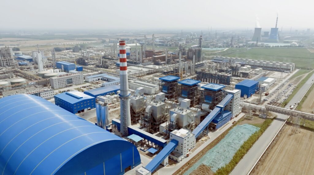
Procurement teams and plant engineers get this wrong more often than they should, and the consequences are not abstract: specify the wrong equipment class, and you are looking at licensing delays measured in months, procurement lead times that blow past your project schedule, and — in the worst case — a pressure boundary that does not meet nuclear quality assurance codes. The terminology overlaps just enough to cause real confusion. Both pieces of equipment move heat using water and steam, both live inside a power island, and vendors sometimes use the terms loosely in commercial literature.
A steam generator in nuclear service is a shell-and-tube heat exchanger that transfers heat from radioactive primary-loop water to a clean secondary loop, producing steam without any combustion. A power plant boiler fires fuel — coal, gas, oil, or biomass — to generate steam directly. In a pressurized water reactor, the steam generator keeps the two fluid circuits physically separated; in a fossil plant, there is only one fluid circuit, and the boiler is both heat source and steam producer.
What makes this genuinely interesting from an engineering standpoint is how differently these two machines are designed once you start pulling on that thread — pressure regimes, material selection, inspection philosophy, tube counts running into the thousands, service lives stretching past forty years. The gap between them is not just semantic. It shapes every procurement decision downstream.
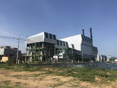
Heat Source and Thermodynamic Working Principle: Combustion vs. Reactor Coolant Loop
The single biggest reason engineers conflate these two devices is that both produce steam. Fair enough. But the source of that thermal energy is so fundamentally different that it shapes every material choice, pressure rating, safety classification, and maintenance interval downstream. Get that straight first, and the rest of the comparison falls into place.
How a Power Plant Boiler Actually Makes Steam
In a conventional utility or industrial boiler — coal-fired, gas-fired, oil-fired, CFB, biomass, MSW, doesn’t matter — combustion happens inside the furnace. Fuel and oxidizer react, releasing flue gas that can reach 1,200–1,600 °C depending on fuel type, excess air ratio, and burner configuration. That hot gas then does two things: it radiates heat to the water-wall tubes lining the furnace chamber, and it flows through convective pass surfaces (superheater, reheater, economizer, air preheater) giving up enthalpy as it cools.
The working fluid — water, or water/steam mixture — sits on the other side of those pressure tubes or the drum. In a subcritical drum boiler the steam separates in the drum and leaves saturated or lightly superheated. In a supercritical once-through design there is no drum at all; feedwater enters one end and supercritical fluid exits the other, at pressures roughly in the 24–28 MPa range and temperatures of 580–620 °C for modern units, though the exact figures depend heavily on turbine inlet design and plant altitude. The point is that heat source and working fluid share only a thin tube wall between them, and the driving force is a temperature difference that can be several hundred degrees across that wall.
No radioactive material. No containment boundary. Just metal, heat, and thermodynamics.
What the Nuclear Steam Generator Actually Does
A PWR steam generator operates on a completely different premise. There is no flame anywhere near it. The heat source is the reactor core, where controlled fission in the fuel assemblies heats pressurized light water — primary coolant — to roughly 315–325 °C at approximately 15.5 MPa. That primary coolant is kept liquid despite its temperature solely by that high pressure. It then circulates out of the reactor pressure vessel, through the steam generator’s tube bundle (thousands of Inconel U-tubes, 19–22 mm OD typically), and back again in a closed primary loop.
Secondary feedwater surrounds those tubes on the shell side. It absorbs heat from the primary coolant through the tube wall and boils, producing steam at around 6.9 MPa — which then drives the turbine-generator. The secondary steam never touches the primary coolant. Those Inconel tube walls are the physical barrier separating radioactive water from the turbine island. That is not incidental to the steam generator’s function; it is a core safety function, formally classified as such under nuclear regulatory frameworks.
In a PWR nuclear steam generator, the secondary steam that drives the turbine is physically isolated from the radioactive primary coolant by the tube bundle walls, making the steam generator a safety barrier with no equivalent function in a conventional combustion boiler.True
This isolation is a fundamental design requirement of PWR nuclear islands; the tube integrity is safety-classified, and tube leaks are a major maintenance and regulatory concern precisely because a breach allows radioactive primary coolant to enter the secondary system.
The Rankine Cycle Path — Where Each Device Sits
In a fossil plant, the boiler is the heat addition step in the Rankine cycle. Feedwater enters, steam exits, and the boiler boundaries define where heat is added to the working fluid.
In a PWR plant the picture is different. The reactor is the heat source; the steam generator is an intermediate heat exchanger inserted between the reactor coolant loop and the steam cycle. The Rankine cycle still runs — condenser, feedwater pump, steam generator, turbine — but the steam generator is not where energy originates. It is where energy transfers from one closed loop to another. That distinction matters enormously for how you size the unit, specify materials, and assign safety classifications.
CANDU and BWR — Two Useful Reference Points
CANDU reactors use heavy water (D₂O) as both moderator and primary coolant, but the steam generator concept is similar: heavy-water primary loop, light-water secondary loop, intermediate heat exchange. The design philosophy is comparable even if the materials and neutronics differ.
A BWR takes the opposite approach entirely — it generates steam directly inside the reactor vessel, which eliminates the steam generator from the nuclear island. Simpler in one sense, but it means the steam driving the turbine is slightly radioactive, which has its own maintenance and shielding implications. For anyone evaluating nuclear island configurations for the first time, the BWR case is a useful thought experiment: remove the steam generator and ask what you gain and what you lose.
A Practical Note for Industrial Boiler Buyers
If you are procuring steam equipment for a process plant or an industrial power project and a vendor describes their product as a “steam generator,” stop and clarify what they actually mean. In commercial industrial practice the term gets applied to fire-tube package boilers, waste heat recovery units (HRSG), electric steam generators for lab or pharmaceutical use, and — rarely, in nuclear parlance — the shell-and-tube heat exchanger described above. They share almost nothing in terms of design pressure, material specification, regulatory framework, or maintenance requirement. Specifying the wrong category at the enquiry stage is the kind of error that surfaces late, expensively, and usually during equipment delivery.
Pressure, Temperature, and Fluid Boundaries: Reading the Design Envelope of Each Device
The nameplate data on a steam generator and a utility boiler look superficially similar — pressures in the megapascal range, temperatures in the hundreds of degrees, large thermal duties. That surface resemblance is exactly where procurement errors happen. Once you read the design envelopes carefully, the devices occupy almost non-overlapping territory.
PWR Steam Generator: Primary Side
On the primary (reactor coolant) side of a pressurized water reactor steam generator, the operating pressure runs at roughly 15.5 MPa — high enough to keep the water liquid even at ~320 °C inlet temperature. The coolant exits the steam generator at around 285 °C, having surrendered maybe 30–35 °C of temperature to the secondary side across that massive U-tube bundle. Design pressure is typically set at 17.2 MPa, providing margin above normal operating conditions for transient excursions.
The critical number that separates this side from anything in conventional boiler engineering is the allowable primary-to-secondary leak rate: on the order of a few milliliters per day per steam generator unit. Not liters. Not even large fractions of a liter. That limit exists because primary-side coolant carries activated corrosion products and, in the event of a fuel cladding defect, fission products. This is why the Inconel 690 or 800 alloy tubing — 3,000 to 16,000 tubes per unit depending on reactor size, each with an OD of roughly 19–22 mm — is manufactured, inspected, and documented to a standard that conventional boiler tube suppliers simply don’t encounter. A conventional boiler tube can have a pinhole and you plug it and keep running. A nuclear steam generator tube leak triggers a formal operability assessment and potentially an outage.
PWR Steam Generator: Secondary Side
Secondary-side steam pressure sits around 6.9 MPa, producing saturated steam at roughly 285 °C. The quality target — the actual fraction of vapor by mass — needs to exceed 99.75% at the steam generator outlet. Miss that target and you’re carrying moisture droplets into a high-speed turbine. At those pressures and flow rates, even 0.5% excess moisture causes measurable erosion on the last-stage blades over a cycle. This is why the moisture separator and steam dryer hardware are integral to the steam generator vessel itself, not bolt-on accessories. You cannot separate the thermal design from the moisture removal design in a nuclear steam generator; they’re the same problem.

Utility Power Plant Boilers: Subcritical Through Ultra-Supercritical
Subcritical drum boilers for utility service typically operate with drum pressures in the 9–18 MPa range, producing superheated steam at 510–570 °C with reheat temperatures in a similar band. Evaporation capacities for large utility units span roughly 200–3,000 t/h — the upper end of that range associated with large 600–1,000 MWe units burning coal or gas.
Supercritical and ultra-supercritical once-through boilers push operating pressure to 24–28 MPa, with main steam temperatures of 580–620 °C and reheat at 600–620 °C. There is no steam drum in these units. Water enters the furnace water walls, passes through the pseudocritical point, and exits as a supercritical fluid without ever forming a two-phase mixture in a drum. The water-wall tube metallurgy has to handle continuous exposure to supercritical water — typically T91 or T92 ferritic-martensitic steels, and austenitic grades in the final superheater stages. Operators who have only run subcritical units sometimes underestimate how different the startup and load-following procedures are; the absence of a drum changes the thermal inertia of the system in ways that catch people off guard.
Industrial Package Boilers: A Different Category Entirely
Industrial fire-tube and water-tube package boilers for process plants operate at 0.7–6.5 MPa producing saturated or lightly superheated steam, with capacities from roughly 1 to 120 t/h. This range overlaps with neither nuclear steam generators nor utility boilers in any meaningful sense. They’re worth mentioning here specifically because procurement teams sometimes conflate “steam generator” as a generic label with these units when writing RFQs. Keep them in a separate conceptual box.
A PWR steam generator secondary side produces superheated steam for the turbine.False
The secondary side of a standard PWR steam generator produces saturated steam (quality >99.75%), not superheated steam. Superheating, if required, is handled downstream. The temperature on the secondary side is limited by the primary coolant temperature, which is itself constrained by reactor design — there is no combustion flame to push steam temperatures higher as in a conventional boiler.
Side-by-Side Design Envelope Reference
| Parameter | PWR Steam Generator | Subcritical Utility Boiler | Supercritical Utility Boiler | Industrial Water-Tube Boiler |
|---|---|---|---|---|
| Operating pressure | ~15.5 MPa (primary) / ~6.9 MPa (secondary) | 9–18 MPa | 24–28 MPa | 0.7–6.5 MPa |
| Steam / outlet temperature | ~285 °C saturated (secondary) | 510–570 °C superheated | 580–620 °C superheated | 170–280 °C (sat. or slightly superheated) |
| Reheat temperature | Not applicable | 530–570 °C | 600–620 °C | Not applicable |
| Capacity range | Thermal duty 500–3,000 MW(th) per unit | 200–3,000 t/h steam | 600–3,000 t/h steam | 1–120 t/h steam |
| Fluid isolation | Hard: primary/secondary barrier; leak limit ~mL/day | Single working fluid; drum separates steam | Single fluid; no drum | Single working fluid |
| Steam quality requirement | >99.75% at outlet | Superheated (quality not the constraint) | Superheated (quality not the constraint) | 95–99%+ depending on process |
The table makes clear that these are not interchangeable specifications. If you’re writing a technical inquiry or a purchase spec and you reach for the wrong row as your reference point, you’ll either over-specify a pressure vessel that the application doesn’t need or — worse — under-specify one that the regulatory framework absolutely requires.
Material Selection and Structural Integrity: Inconel Tubing vs. Alloy Steel Pressure Parts
The moment you look at a bill of materials for a nuclear steam generator versus a utility boiler pressure part list, you realize these are not just different sizes of the same thing. They are fundamentally different engineering problems wearing similar job titles.
Nuclear Steam Generator Tubes: Why Inconel and Nothing Else
Early PWR steam generators used Inconel 600 tubing, and the industry spent decades learning why that was a mistake — stress corrosion cracking (SCC) in high-purity water above 280–300 °C proved far more aggressive than lab data predicted. Plants were replacing entire steam generator bundles years ahead of schedule. The modern standard is Inconel 690 thermally treated (690 TT), which dramatically reduces SCC susceptibility through a combination of higher chromium content (~30 wt%) and a controlled carbide precipitation heat treatment that stabilizes grain boundaries.
Tube wall thickness runs roughly 1.0–1.3 mm on a 19–22 mm OD tube. That sounds thin, but the real structural contribution comes from the tubesheet and the bundle geometry. What that wall thickness does demand is inspection rigor: eddy-current testing of every tube, every outage, with rotating probes capable of detecting flaws at a fraction of a millimeter. A plugged tube is lost heat transfer area. Too many plugged tubes and you’re throttling reactor output. In practice, plants set plugging limits — often around 10–15% of total tube count depending on the utility’s technical specifications — before a steam generator replacement is triggered.
Shell, Channel Head, and Tubesheet: The Forgings Nobody Talks About
The tubes get all the attention, but the structural backbone of the steam generator is low-alloy steel — SA-508 Grade 3 Class 1 for the pressure vessel shell and channel head, per ASME Section III. Because SA-508 has no meaningful corrosion resistance against primary coolant chemistry (high-purity water with dissolved hydrogen and boric acid), every wetted surface gets austenitic stainless steel cladding, typically 308L or 309L applied by weld overlay. The tubesheet itself can reach 500–600 mm thick. That is not a misprint. The tubesheet must resist the differential pressure between ~15.5 MPa on the primary side and ~6.9 MPa on the secondary side across thousands of tube penetrations simultaneously, while also serving as the mechanical anchor for the entire bundle. Machining tolerances and weld inspection requirements on these forgings are extraordinarily tight and represent a significant fraction of the total unit cost.
Power Plant Boiler Pressure Parts: Creep, Not Radiation
A utility boiler engineer’s enemy is creep — the slow, thermally-driven deformation of metal under sustained stress at high temperature. The material selection logic follows the temperature gradient through the unit. Lower furnace water walls and economizer tubing use carbon steel, typically SA-210 Grade A1 or C, which is cost-effective and perfectly adequate below roughly 450 °C metal temperature. As you move into the superheater and reheater where steam temperatures push 580–620 °C on supercritical units, you need T91 or P91 (9Cr-1Mo-V), a ferritic-martensitic alloy with creep rupture strength roughly three to four times that of carbon steel at those temperatures, depending on exposure duration. For advanced ultra-supercritical designs targeting steam above 650 °C, nickel-based alloys like Inconel 617 or the newer 740H start appearing in headers and manifolds — at a material cost that makes procurement managers visibly uncomfortable.
P91 steel requires mandatory post-weld heat treatment (PWHT) at 730–760 °C; skipping or under-soaking this step leads to inadequate tempering of the heat-affected zone and premature creep cracking in service.True
This is a well-documented failure mode. P91 HAZ hardness after welding can exceed 350 HV without proper PWHT, making it brittle and creep-susceptible. Multiple field failures have been attributed to improper PWHT procedures.
CFB boilers add another layer: the furnace enclosure and cyclone separators face aggressive particle erosion from circulating bed material — quartz, ash, unburned char — at velocities that can strip bare metal in a single campaign season. The response is not exotic alloys but refractory lining systems (dense castables, silicon carbide tiles in high-wear zones) combined with membrane wall tubes. This is erosion engineering, not creep or radiation engineering, and the failure modes and inspection intervals reflect that completely.
Fatigue, Cyclic Loading, and Service Life
Nuclear steam generators endure thermal stratification events and occasionally water hammer during load-following transients — conditions that create localized cyclic stresses far removed from the steady-state design point. Fatigue analysis under ASME Section III Appendix XIII methodology accounts for cumulative usage factors across the design transient spectrum. Power plant boilers face their own fatigue challenges from daily start-stop cycling, soot blowing thermal shocks, and attemperator spray events that can induce thermal sleeve cracking if water quality or spray control is poor.
The life management strategies diverge sharply. Nuclear steam generators are typically replaced as complete units every 20–30 years — not because the reactor is done, but because tube degradation (plugging, SCC, fretting wear at support plates) accumulates to the point where replacement is more economic than continued operation with a derated bundle. The reactor pressure vessel meanwhile may have a licensed operating life of 60 years or longer. Power plant boiler components, by contrast, are assessed individually. Remaining creep life calculations on superheater headers, replication metallurgy on high-temperature tubing, and ultrasonic thickness surveys on water walls allow targeted replacement of specific pressure parts rather than wholesale unit changeout. That component-level maintainability is an underappreciated operational advantage of conventional boiler design.
Applicable Codes, Standards, and Regulatory Frameworks: ASME Section III vs. Section I and Beyond
The regulatory distance between a nuclear steam generator and a utility power boiler is not a matter of degree — it is a categorical difference. Procurement teams who treat these as “similar pressure vessels requiring similar paperwork” will hit delays, non-conformance reports, and in some jurisdictions, outright customs holds. Understanding which code governs which device is foundational to writing a valid purchase order, setting up a quality surveillance plan, and clearing import documentation.
ASME Section III: The Nuclear Quality Ecosystem
Nuclear steam generators in pressurized water reactor plants are designed, fabricated, and inspected under ASME Boiler and Pressure Vessel Code Section III, Division 1, Class 1 — the most demanding classification in the ASME system. Every material heat must be traceable. Every weld has a traveler record. NDE (radiographic, ultrasonic, dye-penetrant) is not spot-checked; it is systematic and documented with formal qualification of both procedures and personnel per SNT-TC-1A or equivalent. In US-licensed plants, the nuclear quality assurance program runs under 10 CFR 50 Appendix B, which mandates 18 distinct program elements covering design control, procurement control, corrective action, and records retention — sometimes for the life of the plant plus decades. Outside the US, IAEA NS-G-2.5 provides broadly equivalent guidance, and most national regulators (France’s ASN, China’s NNSA, the UK’s ONR) layer national requirements on top.
The documentation burden alone is staggering. A single Section III Class 1 component may ship with a data package running hundreds of pages: certified material test reports (CMTRs), weld maps, heat treatment records, NDE reports, dimensional inspection certificates, and the N-Certificate of Conformance. Miss one, and the component does not go into the plant — full stop.
ASME Section I, EN 12952, and GB/T 16507: The Utility Boiler World
Utility power boilers operate under a completely different framework. In North America, ASME Section I (Power Boilers) governs, and fabrication requires involvement of an Authorized Inspection Agency — typically a carrier inspection company or a state boiler inspection authority — with final registration on the National Board. In Europe, EN 12952 covers water-tube boilers and is generally implemented alongside the EU Pressure Equipment Directive (PED 2014/68/EU), which assigns conformity categories based on fluid hazard and operating conditions. In China, GB/T 16507 applies to large water-tube power boilers, and the SAMR (State Administration for Market Regulation) oversees type approval and periodic inspection through licensed inspection institutes.
Industrial steam boilers for process applications — the kind you’d install in a food plant, refinery, or district heating system — typically fall under ASME Section I or Section VIII Division 1 depending on pressure rating and intended use. Many countries require local pressure vessel registration before the boiler can be commissioned, periodic hydrostatic proof tests (commonly every 3–6 years depending on jurisdiction), and licensed boiler operators on site. These requirements vary enough between markets that EPC contractors running multi-country projects should audit local requirements in the FEED phase, not the execution phase.
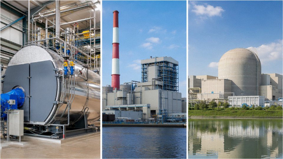
N-Stamp vs. S-Stamp: Why Manufacturer Qualification Is Not Transferable
This is where procurement mistakes get expensive. Manufacturers of nuclear steam generator components must hold an ASME N-Stamp (or NA, NPT, etc., depending on the scope). Obtaining and maintaining the N-Stamp requires a triennial ASME survey of the quality management system, manufacturing capabilities, and document control — a process that takes years and significant investment. An industrial boiler manufacturer holding an S-Stamp (power boilers) or U-Stamp (pressure vessels) is not qualified to supply nuclear Class 1 components, regardless of their fabrication capability.
An S-Stamp certified boiler manufacturer can supply components for a nuclear steam generator if they meet the material and NDE requirements.False
S-Stamp certification covers ASME Section I power boilers only. Nuclear steam generator components require N-Stamp certification under ASME Section III, which involves a separate, far more rigorous QA program, ASME nuclear survey, and design documentation regime. S-Stamp holders must undergo a full N-Stamp accreditation process — they cannot simply extend their existing certification.
Seismic Qualification: Formal Testing vs. Structural Check
Nuclear steam generators must be seismically qualified to site-specific Safe Shutdown Earthquake (SSE) spectra per IEEE 344 or national equivalents. This means shake-table testing or rigorous analytical qualification with documented fragility analysis — not simply a structural adequacy check. Utility and industrial boilers require wind and seismic checks under local building codes (IBC, Eurocode 8, GB 50011, etc.), but these are structural design requirements, not functional qualification against safety-critical operating envelopes. The distinction matters when writing technical specifications: demanding “seismic qualification per IEEE 344” on a conventional boiler is meaningless overreach; failing to require it on a nuclear-safety-class heat exchanger is a serious regulatory gap.
Export Controls and Nuclear Non-Proliferation Compliance
Nuclear steam generator components — and in some cases, even detailed technical data — may fall under Nuclear Suppliers Group (NSG) trigger list controls or dual-use export regulations. In practice, this means an international EPC buyer needs to confirm export license status before issuing a purchase order, not after fabrication begins. Bilateral nuclear cooperation agreements (the so-called “123 Agreements” in the US context) govern what can be transferred to which country under what conditions. Projects in countries without a standing agreement with the supplier nation face potentially long licensing lead times — sometimes 12–18 months or more. Procurement teams unfamiliar with these requirements have delayed reactor projects by conflating nuclear steam generator procurement with ordinary capital equipment purchasing. It is a different process, governed by a different set of authorities, and it deserves early engagement with legal and compliance teams.
Operational Chemistry, Fouling, and Corrosion Control: Why Secondary Water Purity Is a Safety Issue in Nuclear Plants
Water chemistry is where the gap between a nuclear steam generator and a conventional boiler stops being theoretical and starts costing real money — or triggering a regulatory shutdown.
Secondary-Side Chemistry in PWR Steam Generators
The secondary side of a pressurized water reactor steam generator looks, at first glance, like a feedwater system you’d find on any large utility boiler. It isn’t. Sodium, chloride, and sulfate concentrations must be held below single-digit parts per billion — not ppm, ppb — under EPRI’s All-Volatile Treatment (AVT), Oxygenated Treatment (OT), or Phosphate Treatment (PT) regimes depending on the plant’s condenser tube material and historical corrosion record. The regime choice matters because the wrong chemistry for the metallurgy accelerates exactly the failure modes you’re trying to prevent: pitting, crevice corrosion, and stress corrosion cracking of Inconel U-tubes.
A single chemistry excursion — say, condenser in-leakage from a brackish cooling water source during summer peak load — can push chloride above the action level and trigger an NRC (or equivalent national authority) reportable event. That’s not an operational inconvenience. That’s a regulatory process with documentation, root-cause analysis, and potentially a derated power operation until the system is proven clean again.
Primary-Side Chemistry and the Leakage Problem
Primary coolant chemistry adds a layer that has no equivalent in fossil boiler work. Lithium hydroxide (typically 0.2–2.2 ppm Li, adjusted by fuel cycle stage) buffers pH in the high-temperature primary loop, while boric acid concentration — ranging from a few hundred to roughly 2,000 ppm depending on where you are in the cycle — simultaneously controls reactivity. You’re managing pH and neutron economy with the same chemical parameter. That’s a constraint no conventional boiler chemist ever faces.
Primary-to-secondary leakage, even at the low rates typical of a well-maintained unit (often monitored down to fractions of a gram per hour), carries activated corrosion products — Cr-51, Co-58, Co-60 primarily — into the secondary system. Once activity appears in secondary-side samples, the plant enters controlled monitoring protocols. Continued leakage beyond threshold values can force a controlled shutdown for tube plugging or sleeving, a multi-week activity that pulls the unit off the grid. The economics are severe.
Primary-to-secondary leakage in PWR steam generators can introduce radioactive corrosion products into the secondary circuit, requiring activity monitoring under applicable nuclear safety regulations.True
Activated corrosion products from the primary coolant (notably Co-58 and Co-60) can migrate through tube wall defects or imperfect roll transitions into the secondary side, which is why secondary-side activity monitoring is a standard operational requirement at PWR plants worldwide.
Sludge, Tubesheet Deposits, and Chemical Cleaning
Magnetite and — in older plants with mixed-metallurgy feedwater trains — copper oxides accumulate on the tubesheet and in tube support crevices over operating years. This isn’t just a heat transfer issue, though a thick sludge layer will measurably degrade thermal performance. The real concern is under-deposit corrosion: the local chemistry beneath a sludge pile bears no resemblance to the bulk secondary water, and it’s where pitting initiates. Nuclear plants typically schedule chemical cleaning every 6–10 years using reagents such as ARDROX 6038 or similar low-oxidation-potential formulations developed specifically for Inconel compatibility. A cleaning outage runs several weeks and costs, depending on plant size and access constraints, anywhere from a few million to over ten million dollars all-in. It is planned, budgeted, and tracked years in advance. It is not optional.
Conventional Boiler Chemistry: Same Physics, Completely Different Stakes
ASME guidelines for utility drum boilers call for feedwater pH in the 8.5–9.5 range and dissolved oxygen below roughly 7 ppb after deaeration. Coordinated phosphate or congruent phosphate programs manage boiler water alkalinity in the drum. Chemistry excursions cause real damage — caustic gouging and hydrogen damage are both serious failure mechanisms — but they do not involve radioactivity, they do not trigger nuclear safety reporting chains, and the tube replacement decisions are engineering-economic rather than regulatory-driven.
Industrial boilers at 1–2.5 MPa are simpler still. Scale from hardness minerals (CaCO3, MgSO4) is the dominant concern. A softener, a deaerator, oxygen scavenger dosing, and a blowdown regime matched to the makeup water quality covers most situations. Blowdown rate in this context is an energy efficiency lever — every percentage point of blowdown is heat leaving the system — not a safety-critical function.
A Practical Note for EPC Clients
This hierarchy matters enormously at the specification stage. The water treatment package — softener sizing, deaerator capacity, chemical dosing skid, condensate polishing if applicable — must be scoped to match the boiler type and its operating pressure class. A treatment system correctly sized for a 1.5 MPa process steam boiler is not adequate for a 10 MPa utility boiler; the ion exchange capacity, the deaerator operating pressure, and the chemical feed rates are all in different territory. Scope this correctly in the initial EPC package. Retrofitting a condensate polisher or upgrading a deaerator after the civil work is done is expensive and usually involves compromises on vessel sizing that the original layout never anticipated.
Maintenance Strategy, Inspection Intervals, and Replacement Lifecycle: Planned Outage Engineering
The maintenance burden on a nuclear steam generator and a conventional power or process boiler are so different in character that comparing them on a simple cost-per-year basis misses the point entirely. One is a scheduled, high-precision campaign requiring nuclear-grade personnel and radiological controls; the other is a mechanical inspection with well-understood intervals and a fairly predictable spare parts budget. Both demand rigorous planning, but the consequences of getting it wrong diverge sharply.
Nuclear Steam Generator Inspection: Eddy-Current Testing and Tube Management
Every refueling outage — typically every 18 to 24 months depending on the plant’s fuel cycle — the utility must perform eddy-current testing (ECT) on 100% of accessible tubes in each steam generator. With 3,000 to 16,000 Inconel tubes per unit, that is an enormous data volume to acquire, analyze, and disposition in a compressed outage window. The work happens inside a radiologically controlled area, which means all NDE technicians must be qualified at Level II or III, trained in nuclear ECT specifically (EPRI guidelines, not just generic ASME), and subject to dosimetry limits that can pull a technician off the job mid-campaign. Scheduling enough qualified personnel is genuinely one of the harder logistics problems an outage manager faces.
Degraded tubes — those showing pitting, stress corrosion cracking, denting at support plates, or wall thinning beyond the plugging criterion — are either plugged or sleeved. Plugging removes the tube from service permanently. Sleeving restores pressure boundary integrity but requires a precise qualification basis and is not accepted in all jurisdictions. Once cumulative plugging reaches roughly 10–15% of the total tube count (the exact limit is plant-specific and approved by the regulator), the unit is considered to have crossed the economic threshold for replacement. Some plants approach that limit gradually over 20 years; a badly fouled or cracked bundle can get there faster.
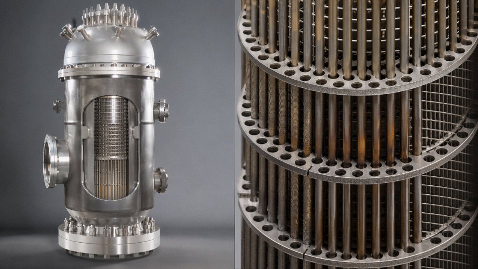
Steam Generator Replacement: A Capital Project Inside an Operating Plant
Replacing a steam generator is not a maintenance activity — it is a major construction project executed inside a licensed nuclear facility under outage conditions. Capital cost runs roughly $150 million to $400 million per unit, depending heavily on labor market, site access, regulatory jurisdiction, and whether the replacement vessel is a direct fit or requires modified nozzle geometry. The work involves reactor head removal, cutting primary coolant piping, rigging out the old unit (these vessels weigh 300–500 tonnes), installing the shop-fabricated replacement, re-welding and post-weld heat treating the primary loop, and performing hydrostatic and leak testing to ASME Section III requirements. The replacement unit itself is fabricated offshore in many cases, transported oversize by sea and then by specialized heavy-haul trailer to the site — a logistics chain that takes months to coordinate before the outage even begins. Done properly, a steam generator replacement extends reactor operating life by 20 to 30 years. The lifecycle math usually supports it, but it requires early commitment; procurement lead times for replacement units are 3 to 5 years.
Nuclear steam generator replacement typically costs $150–400 million per unit and extends reactor life by 20–30 years.True
These figures are consistent with published utility filings and nuclear industry cost studies for PWR steam generator replacement projects in North America and Europe. Exact cost depends on site labor rates, unit count, regulatory scope, and whether the project uses a turnkey vendor or is owner-managed.
Utility and CFB Boiler Planned Maintenance: A Different Kind of Discipline
A large coal-fired utility boiler typically goes down for a planned outage annually or biennially. Duration runs 2 to 6 weeks — shorter for a well-maintained unit with no major findings, longer if the inspection turns up weld cracking on headers, tube wastage in the superheater pendant sections, or refractory damage in the burner zone. The target forced outage rate (FOR) for a competitive generating asset is under 5%, and most well-run plants stay below that if the scheduled maintenance is actually executed rather than deferred.
CFB boilers add their own checklist. Cyclone separator refractory is the item that bites people most often — thermal cycling causes cracking that, if missed, leads to hot gas bypass and rapid shell plate damage. Bed material sampling should happen on a defined schedule (not just “when we think about it”), because shifts in particle size distribution affect combustion efficiency and tube erosion rates. The loop seal and J-valve passages need clearing; plugging there causes bed pressure upsets that can force a unit trip. Erosion monitoring on water-wall tubes in the splash zone around the bed is non-negotiable — wall thickness measurements should be trended, not just spot-checked. Major CFB inspections typically fall every 8,000 to 12,000 operating hours, but the interval depends on fuel quality and operating load profile.
HRSGs in combined-cycle peaking service face a degradation mode that pure baseload thinking underestimates: creep-fatigue damage from thermal cycling. A unit that cycles daily accumulates damage at a rate that a continuous-duty HRSG never sees. Duct burner inspection, HP/IP/LP drum and header examination, and CEMS calibration are the standard items, but remaining-life assessment using finite element analysis of critical welds and headers is increasingly the standard practice for any HRSG with more than 10,000 start cycles.
Industrial Boiler Maintenance: The 1–3% Rule and What It Hides
For fire-tube and package water-tube boilers in process plants — the 2 to 20 t/h range that most factory owners actually deal with — the practical framework is simpler but still requires discipline. Monthly blowdown, quarterly internal visual inspection where access allows, annual third-party inspection by an authorized inspector (AI) as required by most national codes, mechanical or chemical descaling on a schedule tied to feedwater hardness, and burner tune-up every 2,000 to 4,000 operating hours. Skipping the burner tune-up is a common false economy; a poorly adjusted burner running 5% excess air above optimum costs real fuel money over a year.
Total annual maintenance cost for an industrial boiler — parts, labor, inspection fees, water treatment chemicals — usually lands between 1% and 3% of installed capital cost. The low end applies to a well-fed natural gas unit with good feedwater; the high end applies to a heavy-fuel-oil unit running marginal water treatment in a hard-water area. That range sounds comfortable until you realize a forced outage from an uninspected pressure vessel failure in a process plant can cost multiples of the annual maintenance budget in production losses in a single week.
Capacity, Efficiency, and Output Metrics: How to Read and Compare Nameplate Data
Procurement engineers routinely land on a vendor datasheet and immediately hit a units problem. One device is rated in MWt, another in t/h, a third in BHP, and a thermal oil heater shows up in kW with no steam figure at all. None of these are wrong — they’re just measuring different things, and conflating them in a bid comparison is a fast way to under-specify equipment or, worse, select the wrong product category entirely.
Nuclear Steam Generator Output: MWt, Not Efficiency
A PWR steam generator doesn’t have a combustion efficiency figure. There’s no fuel burned inside it; the rating is purely a heat transfer quantity — how much thermal power moves from the primary reactor coolant to the secondary steam cycle. Each unit in a four-loop PWR plant is typically rated somewhere in the range of 800–900 MWt of transferred thermal power, depending on reactor design, tube bundle size, and secondary steam conditions. The four generators together support roughly 1,000 MWe of gross electrical output, though the exact conversion depends on secondary-side steam pressure, turbine efficiency, and condenser performance.
When you see a steam generator datasheet, look for primary inlet/outlet temperatures (typically around 320 °C in, 280 °C out for a Westinghouse-type unit) and secondary steam pressure (roughly 6.5–7.0 MPa). Those numbers, not an “efficiency” figure, define the thermal envelope. Any vendor quoting a combustion efficiency for a nuclear steam generator doesn’t understand the product — or is hoping you don’t.
A nuclear PWR steam generator has no combustion efficiency rating because it contains no burner or fuel; its nameplate output is expressed solely as thermal megawatts transferred between fluid circuits.True
PWR steam generators are shell-and-tube heat exchangers that transfer heat from reactor coolant to the secondary steam cycle. No combustion occurs within the device, so the concept of fuel-based thermal efficiency does not apply. Output is correctly expressed in MWt of heat transfer duty.
Power Plant Boiler Efficiency: What the Percentages Actually Mean
For a utility-scale coal-fired boiler, efficiency is expressed as the ratio of heat absorbed by the steam to the lower heating value (LHV) of the fuel fired. Modern supercritical and ultra-supercritical units run 88–94%, with the upper end achievable only under favorable conditions — clean coal with consistent calorific value, well-maintained air preheaters, and full economizer operation. Drop to 75% load on a variable dispatch unit and efficiency can slip 2–4 percentage points.
Gross heat rate (GHR), expressed in kJ/kWh or BTU/kWh, links boiler performance to the whole generation unit. Supercritical plants targeting modern benchmarks typically achieve GHR below 9,000 kJ/kWh at design load; older subcritical units often sit in the 10,000–11,000 kJ/kWh range. That gap translates directly into fuel cost and carbon intensity over a 30-year plant life — it’s not an academic distinction.
Industrial Boiler Ratings: MCR vs. NCR and Why the Difference Costs Money
Industrial steam boilers — fire-tube, water-tube, CFB, biomass-fired — are rated in tons per hour (t/h) of steam output or in MW of thermal output. North American buyers still encounter boiler horsepower (BHP), where 1 BHP equals roughly 9.81 kW. That unit is fine for small package boilers but gets unwieldy above a few hundred BHP; at that scale, request t/h or MW directly.
The critical thing to pin down before signing a purchase order is whether the published rating is maximum continuous rating (MCR) or normal continuous rating (NCR). MCR is the highest sustained output the boiler can maintain without damage. NCR is the intended operating point, usually 85–90% of MCR, where efficiency and reliability are optimized. Some vendors quote MCR in headlines and bury NCR in the technical annex. A 20 t/h boiler running at NCR might deliver 17–18 t/h under real plant conditions, with feedwater at actual temperature, actual fuel quality, and actual flue gas back-pressure. Specifying against MCR only, without defining feedwater temperature, steam quality, and fuel LHV, is a classic procurement gap.
Thermal Oil Heaters and Hot Water Boilers: Separate Product Categories
Thermal oil (heat transfer fluid) heaters deserve explicit mention here because they appear in multi-utility plant specs alongside steam boilers and get confused with them constantly. A thermal oil heater is rated in kW or MW of heat output — not steam production, because there is no steam. The working fluid (a synthetic or mineral oil) circulates at 200–350 °C at surprisingly low pressure, typically 0.5–1.0 MPa. That low operating pressure is the appeal in certain chemical and rubber processing applications. But it is a fundamentally different product from a steam boiler, with different safety classifications, different piping standards, and different maintenance habits.
Hot water boilers for district heating are rated in MW of heat output, with supply/return temperatures commonly in the 110–130 °C / 70–90 °C range and working pressure from 0.7 up to about 2.5 MPa. With a condensing economizer on natural gas, efficiency can reach 92–96%. They are not, however, interchangeable with steam boilers for process applications that require dry saturated or superheated steam — a distinction that occasionally gets missed in early-stage EPC specs when a client wants to consolidate utility supply.
Procurement Checklist: Six Data Points That Belong on Every RFQ
When issuing an RFQ for any boiler or heat generation device, require the following at a minimum before comparing bids:
| Parameter | Why It Matters |
|---|---|
| MCR steam flow (t/h) and NCR steam flow (t/h) | Defines actual usable output under sustained operation |
| Steam pressure and temperature at boiler outlet | Governs process compatibility and turbine inlet matching |
| Feedwater temperature and pressure at boiler inlet | Directly affects efficiency calculation; vendors often assume high feedwater temp |
| Guaranteed thermal efficiency at 100% and 75% load | Part-load performance matters for variable-demand plants |
| Fuel specification (type, LHV range, moisture, ash) | Efficiency guarantees are only valid for the specified fuel; any deviation voids them in practice |
| Auxiliary power consumption as % of gross output | Fans, pumps, and controls can consume 2–5% of output on large units — relevant for net output budgeting |
In practice, feedwater temperature assumption is where most datasheet comparisons go sideways. A vendor guaranteeing 92% efficiency assumes 105 °C feedwater; your plant has a condensate return at 60 °C. The actual field efficiency will be 2–3 points lower. Always request the efficiency curve as a function of feedwater temperature, not just a single headline figure.
Project Integration, EPC Scope, and Auxiliary Systems: What Comes with Each Device Type
The single most expensive mistake on a boiler or steam generator project isn’t a bad datasheet — it’s a scope gap that nobody catches until the site is already mobilized. Understanding exactly where one vendor’s responsibility ends and another’s begins will save you budget, schedule, and a lot of uncomfortable conversations with your client.
Nuclear Steam Generator: The Nuclear Island Boundary
In a pressurized water reactor plant, the steam generator is not a piece of equipment you procure independently. It comes as an integral part of the Nuclear Steam Supply System, supplied by the reactor technology vendor — Westinghouse, EDF-Framatome, CNNC, Rosatom, or whoever holds the reactor license. The NSSS package typically covers the reactor pressure vessel, reactor coolant pumps, pressurizer, and the steam generators themselves. As an EPC contractor on the conventional island, your interface point is usually the main steam line isolation valve and the feedwater isolation valve at the nuclear island boundary. Everything upstream of those valves — the primary coolant loop, the steam generator shell, the U-tube bundle, primary-side nozzles — is the reactor vendor’s scope, delivered under ASME Section III and the applicable nuclear regulatory authority’s license conditions.
What the conventional island EPC contractor does own: the main steam piping from the isolation valve to the turbine stop valve, the feedwater system back to the steam generator feed nozzle, the condenser and its cooling water circuit, feedwater heaters, condensate extraction pumps, and the turbine-generator island. These are regulated under different codes (ASME B31.1, Section I for any auxiliary steam systems) and inspected by different bodies. Scope confusion at that isolation valve boundary has caused real project delays. Get the P&IDs from the reactor vendor early and mark up the battery limit in red before anything is priced.
Utility Power Plant Boiler: The Full Multi-Discipline Stack
A utility-scale coal-fired or biomass boiler is almost the opposite situation — the EPC scope is enormous and touches nearly every engineering discipline on site. The boiler proper is just the starting point. A complete scope includes the economizer and air preheater (usually supplied as part of the boiler package), electrostatic precipitator or pulse-jet baghouse for particulate control, flue gas desulfurization system, SCR or SNCR for NOx reduction, induced draft and forced draft fans, primary air fans, coal pulverizers or fuel handling conveyors, bottom ash and fly ash handling, the deaerator, HP and LP feedwater heater trains, and the boiler feed pump with its drive and recirculation system. That list spans civil, mechanical, electrical, instrumentation, and environmental engineering — and it routinely involves six to twelve major subcontractors.
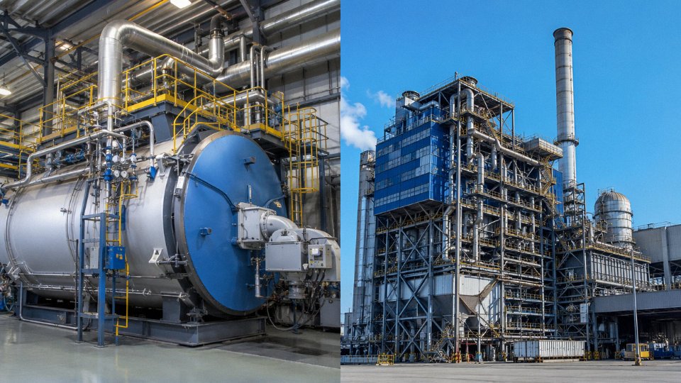
CFB boilers add their own layer of complexity. The primary air fan, secondary air fan, bed ash cooler, cyclone separators, recycle ash system, and limestone feed system for in-furnace SO₂ capture are all tightly integrated with the boiler hydrodynamics. Splitting these items across multiple vendors without meticulous interface management is a well-known path to startup problems — bed temperature instability, refractory cracking at the cyclone inlet, recycle valve hunting. Most experienced CFB OEMs supply these auxiliaries as a coordinated package, and there’s a good reason for that. Resist the procurement temptation to cherry-pick individual items to save 3–5% on capital cost; the integration risk usually costs more than the saving.
[Waste Heat Recovery Boilers](https://coalbiomassboiler.com/product/waste-heat-recovery-boiler/): A Leaner Auxiliary Scope
An HRSG or industrial waste heat boiler sitting downstream of a gas turbine, reciprocating engine, cement kiln, or refuse incinerator operates without combustion air or fuel supply systems entirely. The auxiliary scope shrinks considerably: blowdown vessel, continuous and intermittent blowdown heat recovery, chemical dosing skid, and a stack with CEMS instrumentation. Sometimes a supplementary duct burner is included for peak demand, which adds a burner management system and a small fuel supply line, but the overall package remains much simpler than a fired boiler. The main EPC interface challenge here is coordinating thermal performance guarantees between the primary process vendor (gas turbine OEM, kiln supplier) and the HRSG manufacturer, since the exhaust gas flow, temperature, and composition are inputs the HRSG designer cannot control.
Industrial Package Boiler: What a Complete Factory EPC Package Looks Like
For a greenfield factory — a textile plant, food processing facility, pharmaceutical site, or industrial park — a complete industrial fire-tube or water-tube boiler package should include the boiler vessel and burner, burner management and combustion control system, economizer for flue gas heat recovery, continuous blowdown heat exchanger, pressurized deaerator, chemical dosing unit, boiler feed pump with standby, steam and condensate piping to the battery limit, and a stack with at minimum a CO and O₂ CEMS channel. Taishan Group delivers this complete package for overseas clients, covering engineering, procurement, installation supervision, and commissioning under a single contract — which eliminates the interface disputes that fragment responsibility when these items are purchased separately.
Splitting CFB boiler auxiliaries (primary air fan, bed ash cooler, recycle ash system) across multiple vendors without managed interfaces increases startup risk and typically delays commercial operation.True
CFB boiler hydrodynamics depend on tight integration between combustion air distribution, solids recirculation rate, and heat extraction. Vendor interface gaps in control logic and mechanical connection tolerances are a documented cause of extended commissioning periods on CFB projects.
The Scope Gap That Trips Every Project at Least Once
Regardless of boiler type, the single most common budget surprise is the assumption that the boiler vendor’s scope includes cooling tower makeup, raw water treatment, instrument air compressors, and the HV electrical transformer feeding the boiler island. It rarely does. These are usually owner-furnished utilities or separate EPC packages. Before issuing a letter of intent to any boiler or steam system supplier, define the battery limit precisely in the scope document — fluid tie-in points, electrical supply voltage and metering point, control network handoff, civil foundation responsibility — and verify that each utility supply point is already committed in the project plan. A one-page battery limit drawing reviewed at the LOI stage prevents a six-figure change order at mechanical completion.
Emissions, Environmental Compliance, and Fuel Flexibility: Where Industrial Boilers Diverge Most from Nuclear Steam Generators
A nuclear steam generator produces zero combustion emissions. Full stop. There is no stack, no flue gas treatment train, no SO₂ scrubber, and no NOx permit to negotiate with a regional environmental agency. The environmental regulatory burden on a nuclear plant is entirely different in character — radioactive liquid and gaseous effluents, thermal discharge to the receiving water body, and solid radioactive waste management. Those concerns are governed by nuclear-specific licensing frameworks that have nothing to do with what an industrial boiler buyer needs to worry about. If you are specifying a process steam or power generation boiler for a factory, refinery, or district heating plant, the nuclear steam generator’s environmental profile is simply not your reference point. The comparison ends at the fuel boundary.
Where industrial boilers diverge — and diverge sharply — is in what comes out of the stack and what that costs you to control.
Coal-Fired Boilers: The Full Emissions Stack
Coal is still the dominant fuel for utility and large industrial boilers across Southeast Asia, South Asia, and parts of Eastern Europe, and the emission control scope is substantial. Uncontrolled SO₂ levels depend almost entirely on fuel sulfur content, which ranges from roughly 0.5% in good-quality thermal coal up to 5–6% in some lignite or high-sulfur domestic coals. That translates to a wide spread in scrubber sizing and operating cost. Uncontrolled NOx from a conventional pulverized coal or chain-grate boiler typically runs 300–900 mg/Nm³ depending on combustion temperature, excess air ratio, and burner design — thermal NOx dominates above about 1,300 °C, while fuel-bound nitrogen in the coal contributes a baseline that you cannot fully eliminate with combustion tuning alone.
The standard control technology package for a coal-fired industrial or utility boiler includes an electrostatic precipitator or fabric filter for particulate matter, a wet flue gas desulfurization unit or dry sorbent injection system for SO₂, and selective catalytic reduction (SCR) using a V₂O₅/TiO₂ catalyst bed for NOx. Mercury control, increasingly required under IFC/World Bank Environmental, Health and Safety guidelines and various national standards, is usually handled with activated carbon injection upstream of the fabric filter. Each of these adds capital cost, auxiliary power consumption, and its own maintenance schedule. In practice, the FGD system alone on a mid-sized coal boiler can add 8–15% to the total installed cost, give or take, depending on reagent supply logistics and the local limestone or lime market.
CFB Boilers: Built-In SO₂ Control as a Design Advantage
Circulating fluidized bed combustion changes the emissions economics significantly. The combustion temperature in a CFB furnace sits at 850–900 °C — deliberately low — which suppresses thermal NOx formation to roughly 150–300 mg/Nm³ without any downstream SCR in many applications. More usefully for high-sulfur fuels, limestone injected directly into the bed at a Ca/S molar ratio of around 2.0–2.5 achieves 90–95% SO₂ capture in-furnace. That can eliminate the need for a separate wet FGD unit entirely, which is a real project simplification, especially on remote sites where reagent logistics are a problem.
CFB technology also tolerates fuels that a pulverized coal burner simply cannot handle well — high-moisture lignite, coal washery rejects, petroleum coke, and biomass co-firing up to fairly high blending ratios. This fuel flexibility is not a marketing claim; it is a function of the longer particle residence time and the relatively forgiving bed temperature window.
Biomass and MSW Boilers: A Different Regulated Pollutant List
Biomass and municipal solid waste incineration boilers face a more complex regulatory pollutant list than coal. SO₂ and NOx are still present, but the headline concerns shift to dioxins and furans (PCDD/PCDF), hydrogen chloride from chlorine-containing waste streams, and heavy metals — cadmium, lead, mercury — that concentrate in fly ash and flue gas. The EU Industrial Emissions Directive sets PCDD/PCDF limits at 0.1 ng TEQ/Nm³, and IFC guidelines follow a similar ceiling. Meeting those limits requires activated carbon injection combined with a fabric filter, and the system needs to be designed for the specific chlorine load of the fuel, which varies considerably between agricultural biomass, wood waste, and mixed municipal waste.
For overseas projects, one practical warning: local permit conditions do not always mirror EU or IFC standards, and they can be stricter in some jurisdictions and looser in others. Confirming the enforceable emission limits before finalizing the boiler and flue gas treatment specification is not a formality — getting this wrong late in the EPC process is expensive.
Gas and Oil Fired Boilers: Simpler Stack, But NOx Still Needs Managing
Natural gas and light oil burners are straightforward from an SO₂ standpoint — sulfur content in pipeline gas is essentially negligible, and the PM load is minimal. NOx remains the primary regulated pollutant, typically 80–200 mg/Nm³ with a well-designed low-NOx burner and flue gas recirculation. For industrial gas boilers where efficiency is a priority, condensing economizers that recover latent heat from flue gas moisture can push seasonal thermal efficiency to 98–104% on a net calorific value (lower heating value) basis — the exact figure depends on return water temperature and annual operating hours at partial load, not just the burner rating.
A CFB boiler with in-furnace limestone injection can achieve 90–95% SO₂ removal without a downstream wet FGD unit.True
In-furnace desulfurization via limestone injection at Ca/S molar ratios of 2.0–2.5 is a well-established feature of circulating fluidized bed combustion, documented in ASME, IEA, and OEM technical literature. Removal efficiency depends on limestone reactivity, particle size, Ca/S ratio, and bed temperature control.
Matching Fuel to Technology: What to Provide in Your Enquiry
The right emission control package cannot be specified without knowing the fuel. A proximate analysis (moisture, ash, volatile matter, fixed carbon) and an ultimate analysis (C, H, N, S, O, Cl content) together with gross and net calorific values — GCV and NCV — are the minimum data needed to specify grate type, burner design, or fluidized bed configuration alongside the appropriate emission control train. Ash fusion temperature matters for slagging risk. Chlorine content determines whether HCl control and dioxin suppression measures are necessary.
| Fuel Type | Primary Regulated Pollutants | Typical Control Technology |
|---|---|---|
| Bituminous / sub-bituminous coal | SO₂, NOx, PM, Hg | ESP or FF, wet FGD, SCR, ACI |
| High-sulfur coal, petcoke | SO₂, NOx, PM | CFB with limestone injection, SNCR/SCR |
| Biomass (agricultural/wood) | NOx, PM, HCl | Low-NOx burner, fabric filter, possibly ACI |
| MSW / RDF | PCDD/PCDF, HCl, heavy metals, NOx | ACI + fabric filter, SNCR, wet scrubber |
| Natural gas | NOx | Low-NOx burner, FGR |
| Light / heavy fuel oil | NOx, SO₂ (HFO) | Low-NOx burner, FGD if high-S HFO |
ACI = activated carbon injection; FF = fabric filter; FGR = flue gas recirculation; SNCR = selective non-catalytic reduction
Taishan Group’s engineering team works through this fuel-to-technology matching systematically at the enquiry stage — specifying the grate, burner, or fluidized bed configuration alongside the emission control train as an integrated scope rather than treating the pollution control equipment as an afterthought bolted on later. That integration matters for guaranteed stack emission values, which are what a plant owner actually needs to secure an operating permit.
Frequently Asked Questions About Steam Generators and Power Plant Boilers in Nuclear and Industrial Applications
Can a nuclear steam generator be used as a conventional industrial boiler?
No — and this question comes up more often than you’d expect when clients are evaluating decommissioned nuclear plant hardware. A nuclear steam generator is a shell-and-tube heat exchanger. Full stop. It has no burner, no combustion air ducting, no fuel train, and no furnace enclosure. Its only heat source is the reactor primary coolant loop, which circulates at roughly 15.5 MPa through the tube bundle. Without a nuclear reactor on the other end of that primary circuit, the device is inert. It is also licensed as a nuclear safety-class component under ASME Section III, meaning its entire design basis, traceability documentation, and inspection history are tied to nuclear service. Repurposing it as a standalone industrial steam source is not a matter of engineering adaptation — it is simply the wrong type of equipment for the job.
A nuclear steam generator cannot function as a standalone industrial boiler because it contains no heat source of its own and requires a reactor primary coolant loop to operate.True
Nuclear steam generators are shell-and-tube heat exchangers that transfer heat from reactor coolant to feedwater; they have no combustion system and cannot generate steam independently.
What does “once-through steam generator” (OTSG) mean in a nuclear plant?
In most pressurized water reactors you see a U-tube recirculating design — feedwater enters the secondary side, partially boils, and recirculates until it reaches the steam quality setpoint. The once-through steam generator, used in certain Babcock & Wilcox reactor designs, takes a different approach: feedwater enters at the top of the shell, flows in a single pass across the tube bundle, and exits as steam without any recirculation drum or separator. The shell is noticeably narrower as a result. The tradeoff is sensitivity — OTSG units are more demanding on feedwater chemistry control and flow distribution. Even modest upsets in feedwater quality hit the entire tube length directly, with no recirculating inventory to buffer the transient.
Is an HRSG the same as a nuclear steam generator?
No, despite both carrying the word “steam generator.” A heat recovery steam generator sits downstream of a gas turbine or reciprocating engine and recovers exhaust heat — typically 450–600 °C — to produce steam for process use or combined-cycle power generation. It burns no fuel under base-load operation and has zero nuclear connection. The term “steam generator” in HRSG simply describes the function. Mixing up HRSG and nuclear steam generator in a specification document or an RFQ is the kind of error that wastes weeks in clarification rounds with vendors and licensing bodies alike.
What capacity range should I specify for an industrial steam boiler in a food processing plant?
Food plant steam demand usually falls somewhere between 2 and 30 t/h at saturated pressures of 0.7–1.6 MPa, depending heavily on the specific processes — pasteurization, sterilization, CIP systems, and drying lines all have different load profiles and simultaneity factors. For capacities up to roughly 8–10 t/h, a fire-tube scotch marine boiler is almost always the most cost-effective choice: simpler to install, easier to maintain, and widely understood by plant maintenance teams. Above that threshold, a packaged water-tube boiler gives better efficiency and a faster steam response to sudden load swings, which matters in batch-process facilities. Whatever you calculate as peak demand, add a 20–25% margin. Plants expand, processes get added, and the boiler that was “exactly right” at commissioning is frequently undersized within three years.
How do I compare thermal efficiency figures from different boiler vendors?
Require every vendor to quote on an identical basis: net thermal efficiency referenced to fuel lower heating value (LHV), at maximum continuous rating (MCR), with economizer included, and with feedwater inlet temperature stated explicitly. If you don’t lock that down in the inquiry document, you will receive figures that are not remotely comparable. Efficiency quoted on higher heating value (HHV) will read 3–7 percentage points lower than the same boiler quoted on LHV — the gap depends on fuel hydrogen content and is largest for natural gas. Partial-load efficiency figures can look attractive but tell you nothing about performance during the 60–80% of operating hours when most plants run at or near full load.
What are typical lead times for a utility-scale power plant boiler versus an industrial package boiler?
A subcritical drum boiler for a 300–600 MWe unit generally runs 24–36 months from order placement to site delivery, assuming no major supply chain disruptions on pressure parts or headers. Supercritical units tend to push that to 30–42 months, partly because the thick-wall alloy steel components for 24–28 MPa service require longer forging and heat-treatment cycles. Industrial packaged water-tube boilers in the 10–50 t/h range are a different world entirely — 6–12 months is realistic from a competent manufacturer with an established production schedule. Fire-tube package boilers under 5 t/h are often available from stock or near-stock, with delivery in 8–16 weeks depending on configuration and destination port.
Does Taishan Group manufacture nuclear steam generators?
No. Nuclear steam generators are fabricated by a small number of highly specialized nuclear-licensed manufacturers worldwide — the qualification barriers, material traceability requirements, and regulatory oversight involved are entirely specific to nuclear island equipment. Taishan Group’s scope is industrial and power generation boilers: subcritical power plant boilers, CFB boilers, biomass-fired boilers, MSW incineration boilers, waste heat recovery boilers, thermal oil heaters, hot water boilers, and complete EPC delivery for industrial and utility-scale projects. That portfolio is complementary to nuclear plant infrastructure in the balance-of-plant sense — auxiliary steam systems, plant heating, process steam for non-nuclear island applications — but it does not overlap with nuclear island equipment supply.