
What Are the Key Components of a waste heat recovery boiler?
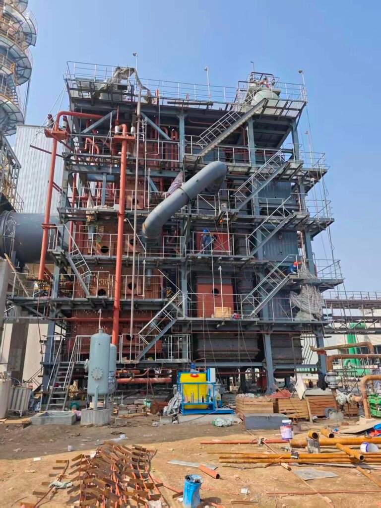
Exhaust gas leaving a cement kiln, a glass furnace, or a reciprocating engine stack carries enormous thermal energy — energy you’ve already paid for in fuel. When that heat vents to atmosphere uncaptured, you’re not just losing efficiency on paper; you’re running a continuous cash bleed, and in many jurisdictions you’re also fighting increasingly tight emissions compliance with one hand tied behind your back. Plants that treat waste heat recovery as an afterthought typically discover the real cost only after they’ve commissioned the unit and found it underperforming, fouling faster than expected, or tripping on drum level instability.
A waste heat recovery boiler (WHRB) captures sensible heat from high-temperature exhaust gases — typically between 300°C and 1100°C — and transfers it to a working fluid (usually water/steam, occasionally thermal oil) through a series of core components: the evaporator, superheater, economizer, steam drum, and supporting auxiliaries including blowdown systems, sootblowers, and instrumentation for drum level and pressure control. Together, these components determine how much of the available exhaust enthalpy — commonly 60–85%, depending on inlet gas temperature and heating surface design — is actually converted into usable steam or hot water.
What makes WHRB design genuinely tricky, compared with a conventional fired boiler, is that you have almost no control over the heat source. The gas flow rate, temperature, and composition are dictated by the upstream process — a kiln, an engine, a furnace — and they shift with production load, fuel quality, and season. That constraint forces every component selection and every geometric decision back onto the thermal designer’s desk. Understanding what each component actually does, where it sits in the gas path, and what happens when it’s undersized or incorrectly specified is the difference between a heat recovery system that pays back in three years and one that sits partially bypassed because the operators got tired of fighting it.
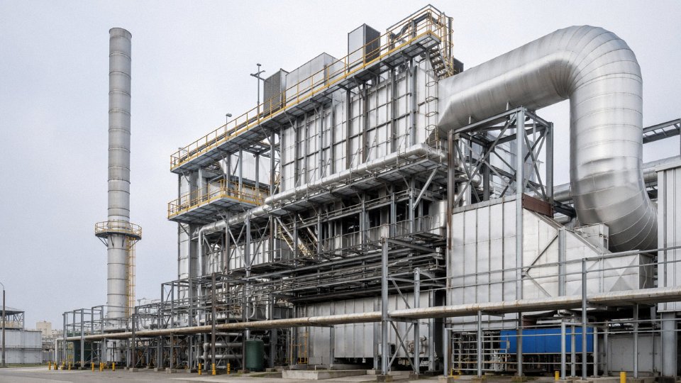
Gas Inlet Duct, Expansion Joints, and Flow Distribution Devices
The gas-side inlet system is probably the most under-specified part of a WHRB package. Clients focus on tube bundle selection, drum sizing, steam conditions — all legitimate concerns — but the hardware between the exhaust source and the first heat-transfer surface quietly determines whether the boiler performs to design curves or spends its life accumulating localized fouling, cracking refractory, and replacing tube rows on a shortened schedule.
Inlet Transition Duct Geometry and Turning Vanes
Hot exhaust rarely arrives at a WHRB in a straight, clean flow path. It comes off a rotary kiln, a glass furnace regenerator, a gas turbine exhaust collector — usually at some angle, often with residual swirl. The transition duct has to decelerate the gas, redirect it if necessary, and deliver it to the first tube row at a reasonably uniform velocity. Get this wrong and you concentrate kinetic energy on a narrow band of tubes. At inlet temperatures above 700°C, that impingement zone erodes and oxidizes fast — tube wall thinning on the exposed face while the shielded tubes run comparatively cool. The thermal gradient alone induces fatigue cycling on tube-to-header joints.
A properly engineered taper reduces duct cross-section velocity from the source connection down to something in the 5–12 m/s range entering the tube field, depending on gas density and allowable pressure drop. Turning vanes — typically fabricated from heat-resistant alloy plate, occasionally from refractory-backed carbon steel at lower temperatures — split and redirect the flow profile. In cement kiln applications with inlet gas at 900–1050°C, these vanes themselves need periodic inspection; scale buildup changes their aerodynamic profile over a couple of operating seasons.
Expansion Joints: Metallic and Non-Metallic Options
The connection between the upstream process duct and the WHRB shell moves. Both structures expand thermally at different rates, react differently to pressure surges, and vibrate. Without adequate movement accommodation, the flange connection cracks, the refractory lining fractures at the joint, and you end up with hot gas bypassing into the insulation — or worse, into the structural steelwork.
Metallic bellows expansion joints, usually multi-ply stainless steel (304H or 316Ti depending on temperature and sulfur content in the gas), handle axial and lateral movement across temperature ranges up to roughly 650–750°C on the external face. Above that, the gas-side liner takes the thermal burden and the bellows handles movement only. Non-metallic fabric joints — woven fiberglass or ceramic fiber composite — are more forgiving of misalignment and handle higher gas temperatures on the process side, but they degrade faster in wet or acidic gas streams. In glass furnace WHRBs where SO₂ content can spike, I’d specify metallic with a ceramic fiber internal liner rather than relying on fabric alone.
Expansion joint failure at WHRB gas inlets is a leading cause of unplanned outages in cement and glass plant heat recovery systemsTrue
Thermal cycling between cold startups and operating temperature (sometimes 600°C+ swings) fatigues improperly rated joints within 2–4 years; correct material selection and movement calculation at the design stage directly extends joint service life to 8–12 years
Movement calculation matters. A 10-meter section of carbon steel duct running from ambient to 550°C expands roughly 55–65 mm axially — the actual number depends on the specific alloy and anchor point configuration. That movement has to go somewhere.
Flow Distribution Baffles and Perforated Plates
Even after the transition duct delivers a reasonably uniform flow, the full cross-sectional velocity profile entering the tube bundle is rarely flat. The gas naturally accelerates toward the center and slows near the walls. Over months of operation, the center tubes accumulate more fly ash, more thermal cycling, more erosion. The wall-side tubes run cooler and, in sulfur-bearing gas streams, risk falling below acid dew point during partial-load operation.
Perforated distribution plates — typically 6–10 mm thick heat-resistant plate with hole patterns calibrated by CFD modeling during detailed engineering — break up the velocity profile and force a more even spread. The open area ratio usually falls between 35% and 55%; go too restrictive and you add pressure drop that the upstream process fan has to overcome, which the process engineer will notice. Intermediate baffles within the gas path serve a secondary function: they also interrupt any tendency for stratified temperature layers to develop across the shell height, which matters when inlet gas temperatures vary seasonally or with process load swings.
Refractory Lining at the Inlet Section
Any zone seeing gas above roughly 600°C needs refractory protection — not just for shell steel integrity but to manage the steep temperature gradient between the gas stream and the pressure boundary. The standard approach uses castable refractory (typically an alumina-based, 40–60% Al₂O₃ formulation) in the hottest zones, backed by ceramic fiber blanket for thermal break, anchored to the shell with stainless alloy hex mesh or individual Y-type studs welded on 150–200 mm spacing. The anchor material matters: standard carbon steel anchors oxidize and lose grip within a year at 650°C. Use 310S or equivalent.
At the very front of the inlet duct — where temperatures and abrasion are highest in kiln or incinerator applications — some designs specify a sacrificial wear-resistant castable layer, harder and denser, sitting in front of the insulating castable. It’s replaceable during planned outages without disturbing the structural lining behind it. A minor point in a spec document, but it saves significant refractory repair cost over a 10-year plant life.
Expansion joints in the refractory itself are non-negotiable. Castable refractory expands, and if you don’t engineer controlled expansion gaps every 1.5–2 meters in long runs, it will crack on its own terms, usually in less convenient locations.
Bypass Damper Systems
The bypass damper is an operational necessity that sometimes gets treated as an optional accessory. In practice, the upstream process — a kiln, a furnace, a turbine — cannot always wait for a boiler to come back online. Planned maintenance, tube leak repairs, chemical cleaning: all require taking the WHRB out of service while the gas source keeps running.
A properly designed bypass system diverts exhaust gas around the boiler through a parallel duct, controlled by a guillotine or louvre damper. Guillotine dampers are more common in high-temperature, high-dust applications (cement, waste incineration) because the blade design sheds accumulated dust more reliably than louvre arrangements. Actuation is typically pneumatic for faster response, hydraulic where high-force closure against differential pressure is required — the choice depends on duct size and the pressure differential the damper must seal against. For a guillotine on a 2.5 × 3-meter duct cross-section in a cement kiln application, hydraulic actuation is usually the practical answer.
Interlocks matter here. The bypass damper open position and the WHRB isolation damper closed position need to be positively confirmed — mechanically or through limit switches — before any maintenance access to the gas side. This is basic lockout-tagout practice, but the specific interlock logic needs to be engineered into the control system at the design stage, not added as an afterthought during commissioning.
Evaporator Section: Tube Bundle Design, Circulation, and Drum Arrangement
The evaporator is the workhorse of any waste heat recovery boiler. It absorbs the bulk of recoverable enthalpy from the exhaust gas stream and converts feedwater into saturated steam — and in a well-designed WHRB, it typically occupies 55–70% of the total heat transfer surface area. That proportion varies depending on how much superheat or economizer surface is specified, but if you’re quoting a project and the evaporator share is below 50%, somebody needs to recheck the thermal design.
Horizontal vs. Vertical Gas Flow: More Than a Layout Preference
The choice between horizontal gas flow (HGF) and vertical gas flow (VGF) configurations gets decided early, and it drives almost everything downstream — tube orientation, structural steel, blowdown access, and soot-blower nozzle placement.
In a horizontal gas flow WHRB, exhaust gas travels horizontally across vertical tube bundles. This is the more common arrangement in cement kiln WHR, glass furnace recovery, and steel reheat furnace applications, partly because it suits long, rectangular duct geometries and makes gravity-assisted natural circulation straightforward. Tube supports are simpler, and personnel access platforms at each bundle bay are relatively easy to configure. The downside: ash and particulate tend to settle on the lower tube rows, so soot-blower coverage — typically retractable or rotary type, one blower per two or three tube rows depending on dust loading — has to be planned carefully or you’ll have hot spots and localized corrosion within 18 months.
Vertical gas flow designs, where gas travels upward or downward through horizontal tube banks, suit compact footprints and are common in waste-to-energy WHRBs and some petrochemical process heater exhausts. Downward gas flow with horizontal tubes gives you gravity-assisted ash fallout, which is actually helpful in high-particulate streams. Access platforms become more complex — you’re essentially wrapping platforms around a vertical vessel rather than walking along a duct — and the structural loading on the tube sheets is different.
Natural Circulation vs. Forced Circulation: When the Physics Decides for You
Natural circulation relies on the density difference between the steam-water mixture in the riser tubes and the subcooled water in the downcomer tubes. For this to work reliably, the circulation ratio — the ratio of total water flowing through the circuit to the steam generated — needs to sit in the range of roughly 15:1 to 25:1. Below that, you risk stratification and departure from nucleate boiling in the riser tubes, which is a fast path to tube failure.
Natural circulation works well when the evaporator is operating with inlet gas temperatures above roughly 400°C and the drum is positioned high enough to give adequate hydrostatic head to the downcomers. Steam pressures up to around 6–7 MPa are usually manageable with natural circulation in industrial WHRB applications, though specific geometry matters.
Forced circulation is always more reliable than natural circulation in waste heat recovery boilersFalse
Natural circulation is inherently simpler and has no pump failure risk. Forced circulation (pump-assisted) is preferred when gas temperatures are low or variable, when the pressure exceeds roughly 8–9 MPa and density differentials narrow, or when the boiler footprint forces a drum position that can't provide adequate hydrostatic head. Neither is universally superior — it depends on the heat source profile.
Forced circulation uses dedicated boiler circulating pumps — typically centrifugal, single-stage, with mechanical seals rated for high-temperature water — to drive flow through the evaporator circuit regardless of thermal driving force. You need pump redundancy (at minimum N+1 standby), and the control logic has to handle startup transients carefully. In practice, forced circulation becomes the sensible choice when inlet gas temperatures are below about 300°C, fluctuate heavily (like in an intermittent process furnace), or when the design pressure pushes above 8.5 MPa and the density differential driving natural circulation becomes too small to trust.
Tube Material Selection: Matching Metal to the Gas Side Reality
Carbon steel SA-210A1 handles the bulk of evaporator duty in moderate-temperature applications — typically where the tube metal temperature stays below about 450°C. It’s cost-effective and widely available in the wall thicknesses needed for boiler drum circuits.
Once you’re in the first-pass evaporator sections where gas inlet temperatures run 600°C or above, alloy steel enters the picture. SA-213 T11 (1.25Cr-0.5Mo) and T22 (2.25Cr-1Mo) are the workhorses here, offering better creep resistance and oxidation resistance at elevated metal temperatures. The selection between T11 and T22 usually comes down to the tube wall temperature calculation, not just the gas temperature — wall temperature depends on heat flux, flow velocity inside the tube, and the tube OD/ID ratio.
Finned tubes versus bare tubes: high-dust gas streams — cement kilns, electric arc furnace exhaust, some biomass combustion gases — essentially prohibit finned tubes in the evaporator section. Fins trap ash, create bridging, and accelerate corrosion under deposits. Bare tubes with wider pitch (typically 1.5–2.0 times tube OD, depending on particle size and loading) are the right call. Finned tubes make sense in clean gas streams like combined cycle HRSG applications where heat transfer enhancement pays off without fouling penalty.
Steam Drum Internals: Where Steam Purity Gets Made or Lost
The steam drum in a WHRB evaporator circuit does more than separate steam from water. What’s inside determines whether the steam leaving the drum is clean enough for turbine use or process injection — and a drum designed with inadequate internals will produce wet, contaminated steam that causes silica carryover, deposits on superheater tubes, and turbine blade erosion downstream.
Chevron-type steam-water separators (cyclone primary separators followed by chevron secondary demisters) are the standard in industrial WHRB drums. Primary cyclones handle the high-velocity steam-water mixture coming up the risers; the chevron pack catches the remaining droplets. Target moisture content leaving the drum is typically below 0.5% by mass, and for turbine steam it should be under 0.1%.
Feedwater distribution pipes run the length of the drum below the water surface — usually slotted pipe headers — to introduce cold feedwater without thermal shocking the drum shell or disrupting the water surface. Continuous blowdown connections are positioned at the water surface level to remove concentrated dissolved solids before they reach the carryover threshold. Chemical dosing connections for phosphate treatment (in drum pressure regimes) are separate nozzles, placed to avoid localized concentration near tube inlets.
Safety valve nozzles are positioned on the steam drum top in compliance with ASME Section I, EN 12952, or GB/T 16507, depending on the destination market — and this is not a detail to sort out after fabrication starts. The nozzle reinforcement calculations and the valve capacity certification need to be locked in during the pressure parts design stage.
Superheater and Reheater Assemblies: Materials, Spacing, and Temperature Control
The evaporator hands off saturated steam, and the superheater’s entire job is to make that steam useful — whether for a back-pressure turbine, a process dryer, or a combined-cycle power block. Saturated steam at even 2.5 MPa carries entrained moisture risk and expands poorly through turbine stages. Superheating to 350–540°C (the actual target depends on the downstream turbine inlet specification or process requirement) removes that problem entirely and improves thermodynamic efficiency in the Rankine cycle. In a WHRB context, the superheater sits closest to the gas inlet, where flue gas temperatures are highest — which means it also bears the most severe thermal and corrosive load in the entire unit.
That’s why tube material selection here is not a procurement shortcut opportunity. It is the most consequential metallurgical decision in the whole WHRB design.
Tube Material Selection: Getting This Wrong Is Expensive
For steam-side metal temperatures up to roughly 540°C, SA-213 T11 (1.25Cr-0.5Mo) handles the duty reliably and costs less than the higher-alloy options. Most industrial WHRB applications in the 1.6–4.2 MPa range land here. Step up to T22 (2.25Cr-1Mo) when metal temperatures push toward 570–580°C — cement plant WHRBs behind preheater exit gases often fall in this zone. Once you’re consistently above 580°C on the metal surface, T91 (9Cr-1Mo-V) becomes the practical choice; it carries substantially better creep rupture strength and oxidation resistance, though it demands more careful welding procedures and post-weld heat treatment that some field contractors underestimate.
SS 347H is a different animal — austenitic stainless, higher cost, not typically chosen for temperature alone. Where it earns its place is in gas streams with elevated sulfur trioxide concentrations or significant chloride content, particularly flue gas from waste incineration or certain non-ferrous smelter off-gases. Austenitic grades tolerate the corrosive chemistry better than ferritic Cr-Mo steels, but their higher thermal expansion coefficient means the support and spacing hardware needs careful design to avoid stress concentration at tube-to-header joints.
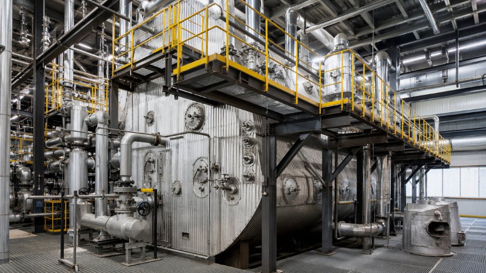
Tube Pitch and Spacing: A Real Trade-Off
In a clean gas application — combined-cycle HRSG behind a gas turbine, for instance — relatively tight transverse pitch (roughly 1.3–1.5× tube OD) maximizes heat transfer surface in a compact shell cross-section. In cement or steel plant exhaust carrying significant particulate loading, that tight pitch will bridge and plug within weeks. Wider transverse pitch, typically 2.0–2.5× tube OD or beyond depending on particle size and loading, keeps lanes open for ash to pass through. The penalty is a larger shell cross-section to achieve the same total heat transfer surface area, which adds fabricated steel weight and footprint. In practice, many cement WHRB designs also slope the tube banks or use staggered arrangements specifically to shed dust accumulation — not something you see in textbook HRSG design, but common on real installations.
Wider tube pitch in high-dust superheater sections reduces fouling risk but increases required shell cross-section area and capital cost.True
Basic heat transfer geometry: for a fixed total surface area, wider pitch requires more tubes arranged over a larger flow cross-section. This is a known engineering trade-off in industrial WHRB design for dusty gas environments.
Attemperation: Why Single-Stage Superheating Creates Control Problems
Spray-type attemperators — essentially a nozzle injecting demineralized water directly into the steam path between superheater stages — are the standard mechanism for trimming final steam temperature. The design target is typically ±5°C around setpoint, which matters when you’re feeding a turbine with tight inlet temperature limits. A single-stage superheater with attemperation at the outlet has limited authority: if the gas temperature swings (load changes upstream, bypass damper position shifts), you may overshoot or undershoot before the control valve responds. Multi-stage designs with intermediate desuperheating between primary and secondary superheater bundles give the control system more headroom — you absorb a large swing in the first stage and fine-tune in the second. The demineralized water supply needs reliable pressure and conductivity control; scale-forming water introduced here deposits directly on superheater tube interior surfaces, which is a failure mode that’s slow to show up and expensive to fix.
Reheater Assemblies in Combined-Cycle and Back-Pressure Configurations
Not every WHRB needs a reheater, but combined-cycle installations with a high-pressure turbine exhaust stage do. The reheater takes partially expanded steam from the HP turbine outlet — typically at lower pressure, often 0.5–2.0 MPa depending on the turbine design — and raises its temperature back up before it enters the LP or IP turbine stage. This improves cycle efficiency and, critically, reduces moisture content at the LP turbine last stage blades, where erosion is a known problem.
Placement within the WHRB gas path puts the reheater in a lower-temperature zone than the primary superheater, which usually allows T11 or T22 tube material even in units where the superheater proper uses T91. One detail that gets overlooked during commissioning: drainage. Reheater tubes must have low-point drains that open during startup and cool-down, because condensate standing in horizontal or near-horizontal tubes will cause water hammer when steam flow resumes — a loud, sometimes violent event that can crack header welds. Specify drain valve interlocking with startup sequence logic; treating it as a manual operator task is an invitation for someone to skip it on a cold Monday morning startup.
Economizer Section: Feedwater Preheating, Acid Dew Point Management, and Materials
The economizer sits at the cold end of the gas path — after the evaporator and any superheater — and its job is straightforward on paper: squeeze the remaining heat out of exhaust gas to warm feedwater before it enters the steam drum. In practice, it’s the section that causes the most corrosion headaches, and it’s frequently under-designed by engineers who treat it as an afterthought once the evaporator geometry is settled.
What the Economizer Actually Recovers
Feedwater entering from the deaerator typically arrives at around 105°C, give or take depending on deaerator operating pressure and condensate return rate. A well-sized economizer raises that to somewhere between 170°C and 210°C, depending on available exhaust gas temperature, surface area, and how aggressively the designer wants to push the exit flue gas temperature down. That drop in exit gas temperature — usually 30–60°C across the economizer — translates to a real efficiency gain of roughly 3–6 percentage points at the system level. Not dramatic in isolation, but on a 20 t/h WHRB running continuously, that’s a meaningful fuel-equivalent saving over a year.
The economizer is always a counterflow arrangement — feedwater enters at the cold end where exhaust gas exits, and exits toward the drum at the hot end where gas enters the economizer bundle. That’s not optional. Running it co-current would collapse the log mean temperature difference and make the surface area requirement impractical.
Acid Dew Point: The Failure Mode Engineers Underestimate
When the exhaust gas comes from a sulfur-bearing source — burning high-sulfur heavy fuel oil, processing off-gas from copper or lead smelting, or even moderate-sulfur coal in a cement kiln — SO₃ is present in the gas stream. SO₃ combines with moisture to form H₂SO₄ vapor, and when tube wall temperature drops below the acid dew point, that vapor condenses directly onto the metal surface. Sulfuric acid condensation at even 5–10% concentration is aggressive enough to pit carbon steel within a single heating season.
The acid dew point in industrial WHRB applications typically falls between 120°C and 160°C, and the actual value depends on SO₃ concentration in the gas, not SO₂ — SO₃ is a small fraction of total sulfur oxides but does almost all the condensation damage. In my experience, plants that only measure SO₂ in their flue gas analysis and ignore SO₃ conversion rates are the ones that open up their economizer casing after two years and find deeply pitted tubes.
Feedwater inlet temperature must be held above the acid dew point to prevent H₂SO₄ condensation on economizer tube surfacesTrue
When tube wall temperature falls below the acid dew point (typically 120–160°C for sulfur-containing exhaust), H₂SO₄ vapor in the flue gas condenses on the metal, causing accelerated corrosion. Controlling feedwater inlet temperature via recirculation is a standard engineering countermeasure in WHRB design.
To protect against this, two control strategies are used together in most serious designs. First, a recirculation pump draws hot water from the drum outlet or economizer exit and mixes it back into the feedwater inlet, raising the inlet temperature above the dew point threshold even during low-load conditions when incoming feedwater would otherwise be too cold. Second, a thermal bypass valve modulates recirculation flow automatically based on a measured inlet temperature, not a fixed setpoint — because the dew point itself shifts with fuel sulfur content and load.
Material Selection at the Cold End
For economizers operating above the dew point on relatively clean gas, plain carbon steel (SA-210 or equivalent) handles the temperature range fine. The trouble starts below the dew point, which is where condensing economizer designs intentionally operate to extract latent heat from flue moisture — a legitimate strategy for gas-fired applications where condensate is only weakly acidic.
For mild acid exposure, Corten-type weathering steel alloys (the CorTen-A and CorTen-B family, or equivalent Chinese-standard equivalents like 09CuPCrNi) offer meaningfully better corrosion resistance than plain carbon steel, at modest cost premium. Cast-iron gilled tubes are an older but still practical choice for the coldest rows — cast iron’s corrosion rate in dilute H₂SO₄ is lower than carbon steel, and the thick walls tolerate some surface loss before integrity is compromised. Teflon-coated tubes show up in some European condensing economizer designs for gas-fired boilers, though they’re expensive and sensitive to gas temperature spikes above around 250°C.
Finned Tube Construction and Fouling Tradeoffs
Most industrial economizers use helical solid fins or serrated (segmented) fins on bare tubes, and the choice depends heavily on dust loading in the gas stream. Serrated fins give better heat transfer per unit area — the interrupted fin surface breaks up the boundary layer — but they trap particulate much more readily than solid fins. On clean gas from a gas turbine exhaust, serrated fins are fine. On exhaust from a rotary kiln or any gas carrying significant fly ash or process dust, solid fins or even bare tubes are safer long-term because they’re actually cleanable with sootblowers or water washing.
Fin pitch and height matter for pressure drop. A pitch-to-fin-height ratio below about 1.5:1 in high-dust applications tends to bridge with deposits within weeks in my experience, driving gas-side pressure drop up and killing draft margin. Most reputable WHRB fabricators target a minimum gas lane clearance of 6–10 mm on the finned surface for dusty applications, though that number shrinks on clean-gas units where fouling isn’t the governing concern.
Sootblower placement in the economizer section is worth specifying explicitly in the contract — not assumed. Retractable sootblowers or fixed lance blowers positioned at each tube row bank, on the gas inlet side of each bundle, prevent the compacted-ash scenario that otherwise requires full bundle removal to fix.
Soot Blowing Systems, Ash Hoppers, and Gas-Side Cleaning Mechanisms
Fouling is the slow killer of WHRB performance, and it’s the one thing operators underestimate until they’re staring at a heat rate deviation they can’t explain. In high-particulate exhaust streams — cement clinker cooler off-gas, electric arc furnace (EAF) fume, biomass combustion flue gas — fine dust and condensed alkali compounds settle on tube surfaces continuously. The deposit builds in layers. A 1 mm layer of cement kiln dust or fly ash can push thermal resistance up by roughly 15–30%, depending on deposit density and composition. At 3–4 mm, you’re looking at measurable steam output drop and elevated exhaust stack temperature. The boiler hasn’t failed. It’s just slowly getting worse every shift.
A 1 mm dust deposit on WHRB tube surfaces can increase local thermal resistance by 15–30% depending on deposit bulk density and mineralogical composition.True
Thermal resistance scales with deposit thickness and inversely with deposit thermal conductivity; cement and alkali-rich deposits typically have conductivities in the 0.1–0.3 W/m·K range, substantially lower than carbon steel, making even thin layers thermally significant.
Retractable Steam Soot Blowers
Retractable lance-type soot blowers are the workhorse for superheater and evaporator sections where tube bundle depth demands real lance penetration — insertion travel typically ranges from 1.5 m to over 6 m depending on casing width. The lance rotates while traveling, so the nozzle sweeps a helical cleaning path across the tube bundle. Steam supply pressure runs between 0.8 and 1.5 MPa; superheated steam is preferred over saturated steam whenever available because it carries less moisture and causes less thermal shock to tube surfaces — a real concern in superheater zones already operating at 450–580°C. Getting wet steam into a hot superheater section is a fast way to induce stress cracking at weld toes.
Modern installations run the blowing sequence through a PLC-based automated controller. The program staggers blower actuation across zones, so you’re not dumping steam consumption in one spike, and you’re not blowing all sections simultaneously (which can cause localized gas velocity surges). In a well-configured system, total soot blowing steam consumption typically runs 0.5–1.5% of main steam output, though this climbs in cement applications where blowing frequency needs to be higher.
Rotary and Acoustic Cleaning Options
In economizer and air preheater zones, casing depth is often too shallow for full lance travel. Short-travel rotary soot blowers — fixed-position units that rotate nozzles through a fixed arc — handle these zones adequately for medium-particle-size dust. For very fine, low-density dust typical of dry-process cement kilns, acoustic horns are worth considering as a supplement. They’re low-abrasion, cause no thermal cycling stress, and can run continuously. They won’t dislodge sintered or caked deposits, but for keeping light dust mobile between manual cleanings, they work reasonably well. Don’t rely on them alone in EAF or biomass applications where sticky, high-alkali deposits form.
Ash Hopper Design and Extraction
Below each tube bundle section, hoppers collect falling dust and slag. Hopper slope angle is critical: minimum 55–60° from horizontal for fine cement dust, which has poor flowability and bridges easily at shallower angles. In practice I’ve seen engineers spec 50° thinking it’s close enough, then deal with weekly hopper cleanouts because the ash won’t flow. Valley angles at hopper intersections need the same attention. Electric trace heating or steam coil heating along hopper walls prevents moisture condensation — important in any application where gas contains SO₂ or HCl, since condensation at the cold hopper skin produces acid that attacks carbon steel rapidly.
Ash extraction uses either rotary airlocks (for batch or semi-continuous removal) or pneumatic conveying for higher-volume applications. The connection between the hopper and the conveying line needs a flexible boot seal; rigid connections crack from thermal expansion.
Inspection Access and Offline Water Washing
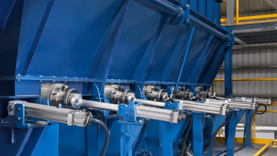
No automated cleaning system eliminates the need for periodic manual inspection. Access doors — sized for a person to enter with tools, not just a viewing port — should be positioned at each major tube bundle zone. Inspection windows with quartz or borosilicate glass let operators do a quick visual during operation without opening the casing.
Offline water washing is necessary every 12–24 months in high-sulfur or high-alkali environments. The procedure involves isolating the gas side, cooling the unit, and washing down tube surfaces with low-pressure water to dissolve soluble sulfate and chloride deposits before they absorb moisture from the atmosphere and form acid solutions. Drain provisions at the lowest points of each section are not optional. Skipping this cycle in a biomass WHRB handling agricultural residue exhaust — high potassium, high chlorine — tends to mean accelerated external tube corrosion that shows up as pitting discovered only during the next unplanned outage.
Steam Drum, Pressure Parts, and ASME / EN Code Compliance for WHRB Pressure Vessels
The steam drum is the single most consequential pressure vessel in a waste heat recovery boiler. Everything else — evaporator tubes, superheater circuits, economizer — feeds into or out of it. Get the drum design wrong, or skip proper code certification, and you’re not just looking at a safety issue. You’re looking at a unit that can’t be insured, can’t pass third-party inspection, and in export markets, can’t legally operate.
Steam Drum Shell: Material Selection and Design Pressure Margins
Shell plate material for WHRB steam drums is almost universally SA-516 Gr.70 in ASME-jurisdiction projects — it’s a fine-grain carbon steel with good notch toughness down to around -29°C, which matters in cold-climate installations where the drum may sit outdoors. European projects typically specify EN 10028-2 P265GH, which is functionally comparable but comes with its own mill certification format and impact test requirements. Neither material is exotic or expensive; the cost risk is in substitution — a supplier who swaps in a lower-grade plate to cut cost without disclosing it. That’s precisely why material traceability documentation (discussed below) exists.
ASME Section I PG-67 requires that the stamped maximum allowable working pressure (MAWP) carry at least a 10% margin above the actual operating pressure. In practice, for a drum operating at 3.8 MPa, you’d design to roughly 4.2 MPa MAWP minimum, though most competent manufacturers push slightly higher to give themselves tolerance on nozzle reinforcement calculations. Nozzle openings in the drum shell require reinforcement analysis per the relevant area-replacement method — this is not optional paperwork; it directly governs whether a nozzle weld will survive cyclic pressure loading over a 20-year service life. Manway requirements under ASME Section I call for an opening no smaller than 300 × 400 mm elliptical or equivalent circular, with the hinge arrangement allowing single-technician entry during scheduled internal inspections.
Headers and Weld Procedure Discipline
Distribution headers — the inlet and outlet boxes connecting tube bundles to the main steam circuits — are smaller pressure vessels in their own right. A superheater outlet header on a mid-size WHRB might be 219 mm OD with 25–35 mm wall thickness in P91 or P22 alloy steel, depending on steam temperature. Stub tube-to-header welds are typically done GTAW root pass, SMAW fill and cap. That sequence isn’t arbitrary; GTAW gives you clean, fully fused root geometry in a tight stub socket, which is exactly where stress concentration and oxide inclusion are most dangerous.
Post-weld heat treatment (PWHT) is mandatory for alloy steel headers once wall thickness exceeds roughly 19 mm (varies by code and P-number). Skipping or shortcutting PWHT — running the furnace too fast, not holding temperature long enough — causes residual stress that won’t show up in initial hydro testing but will initiate cracking within three to five years of thermal cycling. This is a real failure mode, not a hypothetical.
Code Certification: Why Holding Multiple Stamps Matters
A reputable WHRB manufacturer serving export markets should hold ASME Section I (the “S” Power Boiler stamp) for North American, Middle Eastern, and Southeast Asian projects; EN 12952 certification for EU and associated markets; and GB/T 16507 qualification for domestic Chinese production. These are not interchangeable. An EPC contractor tendering a refinery job in Saudi Arabia under an ASME-specified contract cannot accept a boiler stamped only to GB/T 16507, regardless of how well it’s built.
A manufacturer holding only one pressure vessel code certification is adequate for most international WHRB projects.False
International EPC projects routinely require ASME Section I, EN 12952, or both depending on project jurisdiction. A manufacturer without the relevant code stamp cannot legally certify the pressure parts for that market, regardless of actual build quality. Holding multiple certifications simultaneously is the standard expectation for export-oriented WHRB suppliers.
NDE Requirements and Hydrostatic Testing
Non-destructive examination on WHRB pressure parts follows a fairly consistent pattern across codes, though acceptance criteria differ in the details. Butt welds on drum shells and headers require either radiographic testing (RT) or ultrasonic testing (UT) — RT is still the default for shell seams because film provides a permanent record, but phased-array UT is increasingly accepted and in some configurations gives better sensitivity on thick-wall welds. Nozzle fillet welds and attachment welds get magnetic particle testing (MT) on ferritic materials, or liquid penetrant testing (PT) where MT isn’t applicable.
The hydrostatic pressure test at 1.5× design pressure is the final acceptance gate before shipment. It is not a formality. The drum, headers, and all connected pressure parts are filled, pressurized, held — typically 30 minutes minimum — and visually examined for leakage and deformation. Any failure at this stage sends the unit back for investigation and re-examination, which in a real project schedule means weeks of delay. Getting here cleanly requires every upstream step to have been done correctly.
Material Data Records and Third-Party Inspection
International EPC contractors and plant insurance underwriters will ask for the Material Data Record (MDR) package before they accept any pressure vessel. That package includes: original mill certificates with chemical and mechanical test results traceable to the specific heat and plate number; welding procedure specifications (WPS) and procedure qualification records (PQR); individual welder qualification records (WQR) tied to the actual welders who worked on the unit; all NDE reports with examiner certifications; and PWHT charts with time-temperature records. A third-party inspection (TPI) agency — Bureau Veritas, Lloyd’s Register, TÜV Rheinland, SGS, or similar — witnesses critical fabrication hold points and countersigns the documentation.
Missing or incomplete MDR documentation is one of the most common causes of shipment holds on export WHRB projects. The boiler might be physically ready to load; if the paperwork isn’t complete, it doesn’t move. Plant owners negotiating procurement contracts should explicitly require the full MDR package as a contractual deliverable, not an afterthought.
Feedwater System, Blowdown, and Water Quality Control Circuits
Most plant owners focus their attention on the gas side of a WHRB — inlet temperatures, heat transfer surface area, tube metallurgy. That’s understandable. But in practice, more unplanned shutdowns trace back to the water side than to anything the exhaust gas does. Scaling on the waterwall tubes, oxygen pitting in the economizer, silica carryover into a steam turbine — these failures build quietly over months before they announce themselves as a forced outage or a burst tube.
Deaerator and Feedwater Pump Arrangement
A deaerator isn’t optional equipment on a WHRB circuit. It’s the first line of defence against dissolved oxygen, which attacks carbon steel economizer tubes through a mechanism that looks superficial in early inspections — small, crater-like pits — and then penetrates rapidly once the protective oxide layer is breached.
The standard operating target for a tray-type or spray-type deaerator feeding a drum-type WHRB is roughly 0.12–0.15 MPa, which gives a saturation temperature around 105–111°C. At that condition, dissolved oxygen in the feedwater drops below 7 ppb, sometimes well below, depending on tray condition and steam stripping rate. If the deaerator is undersized, running at too low a pressure, or — and this happens more than it should — bypassed during low-load startup to save time, oxygen levels in the feedwater climb into the 20–50 ppb range and start working on the economizer immediately. You won’t see the damage for six to eighteen months. Then you’ll see it all at once.
Feedwater pump selection for a WHRB needs to account for the relatively modest flow rates combined with potentially high discharge pressure, especially if the boiler is generating steam above 4 MPa. Multistage centrifugal pumps with mechanical seals rated for continuous-duty service are the norm. A standby pump on automatic changeover is non-negotiable for any plant running 24/7.
Chemical Dosing and Water Chemistry Targets
The deaerator gets oxygen down to an acceptable level, but it doesn’t eliminate it entirely. That’s where oxygen scavengers come in — sodium sulfite for systems below roughly 4 MPa (it decomposes above that and creates sulfate deposits), and catalyzed alternatives or low-dose organic scavengers for higher-pressure units. Hydrazine has largely fallen out of favour in most markets now due to toxicity handling concerns, though it still appears in older plants.
Phosphate dosing to the steam drum maintains a residual orthophosphate concentration — typically in the 5–15 mg/L range depending on operating pressure and the specific treatment philosophy — which reacts with hardness ions that slip through upstream softening equipment to form a mobile, non-adherent sludge rather than a hard calcium carbonate or calcium sulfate scale. Hard scale on tube walls is genuinely dangerous: even 1 mm of calcium sulfate scale can raise tube wall temperature by 15–30°C above the design point, depending on heat flux. That margin disappears fast in a superheater or high-flux evaporator tube.
Drum water pH should be held between 10.5 and 11.5. Below that range, corrosion rates on carbon steel and even low-alloy steel accelerate sharply. Above 12, caustic attack becomes a concern, particularly at areas of steam blanketing or high local heat flux — under deposits, at tube joints, near the waterline. The target band is not wide. If your chemical dosing pump fails for a 12-hour shift and nobody catches it on the pH monitor, you’ve already done damage you can’t see yet.
Continuous and Intermittent Blowdown
As water evaporates in the drum, everything dissolved in it stays behind. Total dissolved solids concentrate over time. Left unchecked, TDS rises until dissolved salts begin depositing on tube surfaces or, worse, carry over into the steam as fine droplets — silica carryover into a turbine being the classic nightmare scenario.
Continuous blowdown (CBD) draws a small, steady flow from near the drum waterline, where TDS concentration peaks. The target TDS in drum water varies by operating pressure: a 1.6 MPa system might tolerate up to 3,500 mg/L, while a 9.8 MPa unit needs to stay below roughly 1,000–1,500 mg/L. The higher the pressure, the more aggressively you have to blow down, and the more energy you’re throwing away — unless you recover it.
Intermittent blowdown (IBD) serves a different purpose. Opened manually or on a timer from the drum mud drum, header drain points, and lower headers, it physically ejects the sludge layer that settles at low-flow collection points. IBD typically runs for 30–60 seconds per point, once or twice per shift on plants with moderate hardness feedwater. Skip it for a week in a cement plant application where the process condensate return contains calcium contamination and you’ll find a hardened sludge bed at the header that a short blowdown won’t shift anymore.
Continuous blowdown heat recovery through a flash vessel can recover 10–15% of the thermal energy in the blowdown streamTrue
At typical drum operating pressures of 1.6–4.0 MPa, blowdown water flashed to 0.3–0.5 MPa releases a meaningful fraction of its enthalpy as low-pressure steam. The exact recovery percentage depends on the operating pressure ratio and blowdown rate, but values in the 10–15% range are consistent with standard heat balance calculations for this configuration.
That flash steam — generated at roughly 0.3–0.5 MPa in a simple vertical flash vessel — gets piped directly to the deaerator as supplementary heating steam. It’s not a large energy stream, but on a boiler running 8,000 hours a year, the fuel or steam equivalent adds up to something worth the cost of the flash vessel and a few metres of pipe.
Online Water Quality Monitoring
A bare-minimum online instrumentation package for WHRB water chemistry includes a conductivity analyzer on the CBD line (as a proxy for TDS), a pH monitor on the drum water sample, a dissolved oxygen meter on the deaerator outlet or feedwater pump discharge, and a silica analyzer on the steam sample if you’re feeding a turbine or any process sensitive to silica deposition.
Conductivity alarms are typically set around 150–400 µS/cm on the steam side (depending on pressure class) and higher on the boiler water side. Dissolved oxygen alarms on the feedwater line are commonly set at 10–15 ppb, giving operators a warning band before the 7 ppb target is breached. These instruments need calibration checks every few weeks — in my experience, the dissolved oxygen sensor in particular drifts and gets neglected once the plant is past commissioning. That’s exactly when it matters most.
Water chemistry failures are slow. They don’t trip an alarm the day they start. They show up in a tube inspection two years later, or in a sudden failure during a load swing. Getting the feedwater system right from day one — deaerator sizing, chemical dosing, blowdown discipline, and instrumentation — is genuinely the cheapest form of WHRB maintenance there is.
Instrumentation, Control System, and Safety Interlocks for WHRB Operation
A WHRB sitting between a rotary kiln and a steam turbine is only as reliable as the control architecture wrapped around it. The heat source isn’t something you can throttle — the exhaust keeps coming whether you’re ready or not — so the instrumentation and interlock logic have to handle disturbances faster and more autonomously than most fired boiler applications demand.
Core Measurement Loops and What Each One Actually Drives
Gas-side inlet temperature is typically measured with Type K thermocouples at 300–600 °C applications and Type S above roughly 900 °C, usually at two or three radial positions across the duct to catch any stratification that slipped past the flow distribution baffles. That reading feeds the control system’s enthalpy accounting and, critically, triggers early warning if a cement kiln or glass furnace upstream starts spiking. Gas outlet temperature gets a similar treatment, and the delta between inlet and outlet across each section is the fastest real-time indicator of fouling — a 15–20 °C rise in outlet temperature with constant inlet conditions usually means a soot blower cycle is overdue or a tube surface is scaling.
Differential pressure transmitters across the evaporator, superheater, and economizer sections track gas-side resistance. A gradual ΔP increase points to ash bridging or fouling; a sudden drop, especially after a soot blower fires, sometimes signals tube erosion opening a gap in the bundle. Steam drum pressure uses at minimum two redundant transmitters — one feeding control logic, one feeding the safety interlock — because a single transmitter failure should never be the reason a safety valve doesn’t lift.
Feedwater flow measurement with a vortex or differential-pressure flowmeter closes the mass balance loop and gives the three-element controller its third input. Superheated steam temperature, measured with a thermocouple just downstream of the final superheater pass, drives the attemperator spray valve. Getting this wrong — letting superheated steam temperature walk 20 °C above design continuously — shortens tube life in a way that shows up as a crept failure eighteen months later, not a dramatic event today.
Three-Element Drum Level Control
On any WHRB above roughly 10 t/h steam output, single-element level control (drum level only) is inadequate. The three-element strategy combines drum level, steam flow, and feedwater flow in a cascade arrangement: steam flow acts as a feedforward signal that anticipates demand changes before the drum level has time to react, and the feedwater flow signal closes the inner loop with fast response. This matters because industrial exhaust gas flows are rarely steady — a cold charge going into an electric arc furnace can swing steam demand by 30–40% in under two minutes. Without feedforward, level swell during sudden demand increases, or shrink during load drops, will trip the drum level interlock and dump the whole system into bypass mode at exactly the wrong moment.
Safety Interlock and ESD Logic
The emergency shutdown sequence on a well-designed WHRB typically cascades as follows: high drum pressure (set at roughly 3% above the safety valve setpoint), low-low drum water level (commonly two drum diameters below normal operating level), high superheated steam temperature (usually 15–25 °C above design maximum), gas flow loss, and feedwater pump failure. Any of these conditions triggers automatic opening of the bypass damper to divert exhaust gas around the WHRB, simultaneous closure of the main steam stop valve, and a feedwater pump hold sequence to prevent thermal shock from cold water entering a hot drum. The bypass damper actuator should be fail-open — on loss of instrument air or control power, the damper opens and the boiler is protected. In practice, I’ve seen plants specify fail-close by mistake, which is a serious design error that only shows up during a power failure drill.
A fail-open bypass damper actuator is the correct safety default for WHRB installations where process exhaust cannot be interruptedTrue
On loss of power or control air, the damper must default to diverting exhaust gas away from the boiler to prevent uncontrolled overheating of pressure parts. A fail-close default traps hot gas against heat transfer surfaces with no steam flow to absorb energy, risking tube overheating and pressure part damage.
DCS Integration
Most modern WHRB control panels communicate with the plant-wide DCS via Modbus TCP/IP; PROFIBUS DP is still common in European-supplied plants and older facilities. The integration scope typically includes all analog process values (temperatures, pressures, flows, levels), all discrete interlock states, and setpoint write access for parameters like drum pressure and steam temperature targets. Latency across the gateway usually needs to be under 500 ms for level control stability; anything slower and the cascade loop starts hunting.
A well-integrated system lets the central control room operator see WHRB performance trend data — heat transfer coefficients per section, gas-side ΔP history, steam generation rate — without walking out to a local panel. For plants running multiple WHRBs in parallel off the same process line, this centralized visibility is genuinely valuable during load changes.
Remote Monitoring and Predictive Maintenance
Several manufacturers now offer IIoT-enabled condition monitoring as a standard or optional package. Wireless vibration sensors on circulation pump bearings and soot blower drive shafts feed cloud dashboards that flag developing bearing wear weeks before an audible symptom appears. Gas-side outlet temperature trending, analyzed against a baseline established during commissioning, provides a surprisingly reliable fouling index — one that experienced operators used to track manually on a clipboard, and that algorithms now flag automatically when the deviation crosses a threshold.
Tube wall temperature monitoring via embedded thermocouples in superheater sections is less common but increasingly specified on high-pressure units (above 6 MPa) where creep life management matters. Combined with periodic ultrasonic thickness measurements, this data builds an actual remaining-life picture rather than a scheduled-replacement guess. For remote sites or plants without deep in-house boiler expertise, that kind of early warning infrastructure is worth the added instrumentation cost — usually in the range of 2–5% of total WHRB supply price, depending on scope.
Structural Framework, Casing, and Thermal Expansion Provisions
The structural steel frame of a waste heat recovery boiler doesn’t get much attention in spec sheets, but on a real EPC project it’s often where schedule slippage and field rework originate. Get the support configuration wrong, and you’re shimming baseplates six months after commissioning while the plant owner watches steam leak from a distorted casing joint.
Top-Supported Versus Bottom-Supported Configurations
Most high-temperature WHRBs — anything with gas inlet temperatures above roughly 400°C — are designed as top-supported, or “hung,” structures. The pressure parts, headers, and tube bundles hang from a top steel frame and expand downward freely under thermal load. This matters because it keeps the expansion movement predictable and away from the fixed foundation anchor points. Bottom-supported designs are simpler to fabricate and fine for lower-temperature applications (waste heat from diesel gensets, for instance, or low-grade process gas below 300°C), but they require careful management of upward thermal growth into the inlet duct connection, which creates problems at the expansion joint if the civil team hasn’t accounted for it.
Structural steel for the main frame is typically ASTM A36 or its European equivalent S275JR. Nothing exotic, but the connection details matter more than the grade — particularly the gusset plates at the top beam-to-column junctions, which carry the entire suspended weight of the boiler under operating temperature plus hydrostatic test load. A cement kiln WHRB might have a pressure part assembly weighing 80–150 tonnes depending on capacity. Those connections deserve proper engineering review, not a copy-paste from a smaller unit.
Insulated Casing and Air Tightness
The outer casing is a multi-layer assembly: an inner steel skin (usually 5–6 mm plate), followed by mineral wool blanket insulation in staggered layers totaling 150–200 mm thickness at 500°C service temperature, then an outer corrugated steel cladding that handles weather and mechanical protection. In practice, the insulation thickness at any given point depends on the local gas temperature, the allowable outer surface temperature (typically targeted below 50°C above ambient for personnel safety), and whether the boiler is indoors or exposed.
Casing air tightness is one of those things that gets rushed during installation and causes problems for years afterward. A leaking casing on a boiler processing steel furnace exhaust or sulfur-containing gas doesn’t just lose heat — it leaks SO₂ or CO into an enclosed building. That’s a regulatory and personnel safety issue, not just an efficiency debit.
A casing leak of even 1–2% of gas flow can cause measurable CO concentration buildup in an enclosed boiler house within minutes during an inlet gas upset.True
WHRB inlet gases from steel or chemical processes can contain CO at several thousand ppm; even small casing breaches allow this to accumulate in confined spaces, which is why casing weld inspection and positive-pressure purge testing before commissioning are standard practice on enclosed installations.
Tube Support Systems and Vibration Control
Inside the casing, each tube bundle needs intermediate support plates — essentially steel combs or grids that locate the tubes laterally without restricting longitudinal thermal movement. Carbon steel supports work for the economizer end; alloy steel (typically Cr-Mo grades like 15CrMo or similar) is needed in the superheater region. The sliding-versus-fixed distinction here is worth being precise about: only one support per tube row should be a fixed point; all others must be free to slide as the tube expands axially.
Flow-induced vibration is a genuine failure mode, not a theoretical one. At gas velocities above roughly 12 m/s through a close-pitch tube bundle, vortex shedding frequencies can lock onto tube natural frequencies and cause fretting wear at support contact points within months. Anti-vibration baffles — flat bars welded perpendicular to the tube axis between rows — break up the vortex shedding pattern. This needs to be specified explicitly, not left to the fabricator’s discretion.
Thermal Expansion Calculation and Accommodation
Differential expansion is where many WHRB structural problems actually originate. The outer casing, the pressure part headers, and the tube bundles all heat up at different rates and reach different final temperatures. In a large cement kiln WHRB operating with gas temperatures around 350–450°C at the evaporator inlet, relative movement between the casing and the pressure parts can easily reach 20–40 mm in the vertical direction, and 10–20 mm transversely depending on the geometry. Slide plates under the casing support feet (PTFE-faced stainless steel, or graphite pads in high-temperature zones) accommodate this. Slotted bolt holes in the casing connection brackets handle lateral movement. Flexible seal strips — stainless steel bellows or ceramic fiber rope — seal the gap at sliding interfaces without restraining movement.
These details need to appear in the design calculation package, not just in someone’s head. On more than a few projects I’ve reviewed, the thermal expansion analysis existed for the pressure parts but stopped there — the casing was treated as a static structure, and the field team discovered the problem when expansion buckled a casing panel at the second maintenance shutdown.
Platform, Access, and Civil Interface
OSHA 1910.23 and EN ISO 14122 both set clear requirements for platform width (minimum 450–500 mm clear walkway), handrail height, and stair angle, but the more practical issue on WHRB projects is simply locating platforms early enough that the civil foundation design accounts for the loads. Soot blower drives need access at operating height. Inspection doors — usually located at the inlet duct, between each heat transfer section, and at the outlet — need clear working space in front of them. Safety valve discharge piping needs a platform for inspection without requiring scaffolding. If the civil structural drawings are issued before the boiler vendor finalizes platform locations, which happens often on fast-track EPC schedules, expect RFIs and field steel additions that cost more than doing it once at the right time.
Frequently Asked Questions About Waste Heat Recovery Boiler Components
What is the difference between a WHRB and an HRSG?
The terms get used interchangeably in sales literature, which causes real confusion during specification. An HRSG — heat recovery steam generator — is a subset of the broader WHRB family, designed specifically for gas turbine exhaust: relatively clean flue gas, inlet temperatures usually in the 450–600°C range, and well-characterized mass flow rates. HRSGs routinely use multiple pressure levels (high, intermediate, low) and often incorporate supplementary duct burners to boost output during peak demand.
A WHRB covering cement kiln preheater exhaust, electric arc furnace offgas, or glass furnace waste streams is a different engineering problem entirely. Dust loadings can be 20–80 g/Nm³ or higher, inlet temperatures may reach 900–1100°C in some steel and nonferrous applications, and the gas composition can include corrosive species that a gas turbine HRSG designer would never have to consider. Tube spacing, soot blower frequency, and hopper sizing all change substantially. Calling both units “HRSG” in a procurement specification will get you the wrong equipment.
Which component fails most often, and why?
Superheater tubes. This is consistent across industries and not particularly controversial among maintenance engineers who have spent time doing boiler autopsies. The superheater sits at the hottest end of the gas path, operates at tube wall temperatures that can reach 450–580°C depending on steam pressure (1.6–9.8 MPa range in typical industrial units), and is the first section to suffer when steam flow distribution across parallel tubes becomes uneven — which it inevitably does over time as deposits form or tube geometry shifts slightly. Localized overheating follows, and creep or stress-corrosion cracking develops faster than most inspection cycles catch it.
The second most common failure is the economizer cold end. Feedwater enters here, and if the inlet temperature drops below the acid dew point — roughly 120–150°C for sulfur-bearing exhaust, higher if HCl is present — you get condensate-driven corrosion on the fin or tube outer surface. Plants that run at reduced load in winter, dropping feedwater temperatures seasonally, often discover this the hard way during the next annual shutdown.
Superheater tube failure is the leading cause of unplanned WHRB downtime across cement, steel, and glass industry installations.True
Superheater sections face the highest metal temperatures and are most sensitive to steam flow maldistribution and fouling-driven overheating, making them statistically the most failure-prone pressure part in industrial WHRB service.
How long does a WHRB last, and when do major overhauls fall due?
A well-operated unit — proper water chemistry, functioning soot blowing, annual inspection discipline — should reach 25–30 years of service life without full replacement. In practice, the variables that shorten that are almost always operational, not design: deferred tube cleaning, water treatment shortcuts, or running beyond the original design gas temperature because the upstream process was expanded.
Major overhauls typically fall every 8–10 years and involve tube bundle thickness surveys (ultrasonic testing across a statistically meaningful sample), soot blower lance replacement, refractory repair, and drum internal inspection. Annual shutdowns, shorter, cover hopper cleanout, visual tube inspection, safety valve testing, and blowdown system checks.
Can a WHRB be retrofitted to an existing kiln or furnace?
Yes, and it is done regularly in cement and steel plants. The feasibility questions that actually matter: Is there enough gas flow and temperature to justify the capital? Can the existing structure carry the added load, or does a new support frame need to go in? Is there space for a bypass duct — because you need a reliable gas bypass before any boiler maintenance outage becomes a production shutdown. And critically, can the process tolerate an additional gas-side pressure drop, typically 500–1500 Pa depending on unit size and configuration? Some older induced-draft fan installations have no headroom left and require fan upgrades before the WHRB project is viable.
What certifications should a WHRB manufacturer hold for export projects?
At minimum: ASME Section I “S” Stamp for pressure vessel fabrication, and ISO 9001 for quality management. For European destination projects, EN 12952 compliance and PED 2014/68/EU conformity are not optional — they are required for CE marking and insurance coverage. Third-party inspection by Bureau Veritas, Lloyd’s Register, or TÜV SÜD during fabrication and hydrostatic testing adds a layer of assurance that banks and project insurers increasingly require on capital projects. Asking for a manufacturer’s certificate list is straightforward; asking to see the actual stamp authorization documents and a recent third-party inspection report is what a procurement engineer should actually do.
How is heat transfer area calculated in WHRB design?
Each section — superheater, evaporator, economizer — is sized using either the LMTD (Log Mean Temperature Difference) method or the NTU-effectiveness method, applied to the known gas mass flow, specific heat, and temperature profile alongside tube-side fluid conditions. The overall heat transfer coefficient (U-value) for each section varies with gas velocity, tube geometry, and fin density where applicable. The variable that introduces the most project-specific uncertainty is the gas-side fouling resistance factor. A clean natural gas exhaust stream and a cement kiln bypass gas stream carrying alkali-laden dust require very different fouling allowances, and that difference directly drives tube count and final equipment cost.
What is the pinch point and why does it matter so much?
The pinch point is the minimum temperature gap between the hot exhaust gas and the saturated steam temperature at the evaporator outlet. Design practice typically targets 8–15°C. Narrow that gap toward the lower end and you recover more heat, but the required heat transfer surface area increases sharply — the relationship is nonlinear, and the last few degrees of approach cost disproportionately more tube surface than the first. Widen it and you leave recoverable enthalpy on the table, reducing steam output and ROI. Selecting the right pinch point is genuinely one of the most consequential economic decisions in the design phase, and it should be made with realistic fouling assumptions built in, not clean-surface theoretical values.
References
Guide to Combined Heat and Power Systems for Boiler Owners and Operators — U.S. Department of Energy
Waste Heat Recovery Basics for Industrial Facilities — U.S. Department of Energy
Waste Heat to Power Systems and Applicable Recovery Technologies — U.S. Environmental Protection Agency
HRSG Components, Modules, Headers, Superheaters and Economizers — Babcock & Wilcox
Boiler Economizers and Feedwater Temperature Control — Babcock & Wilcox
Economizers, Superheaters and Specialized Boiler Types — Spirax Sarco
Use Feedwater Economizers for Waste Heat Recovery — U.S. Department of Energy
Industrial Steam System Efficiency and Heat-Recovery Resources — U.S. Department of Energy
Combined Heat and Power and Waste Heat-to-Power Technologies — U.S. Environmental Protection Agency
Power Boiler Superheater, Economizer and Pressure-Part Components — Babcock & Wilcox
What Are the Key Components of a waste heat recovery boiler? Read More »