August 3, 2026

Industrial Steam Boiler Sizing: Capacity Calculation Guide
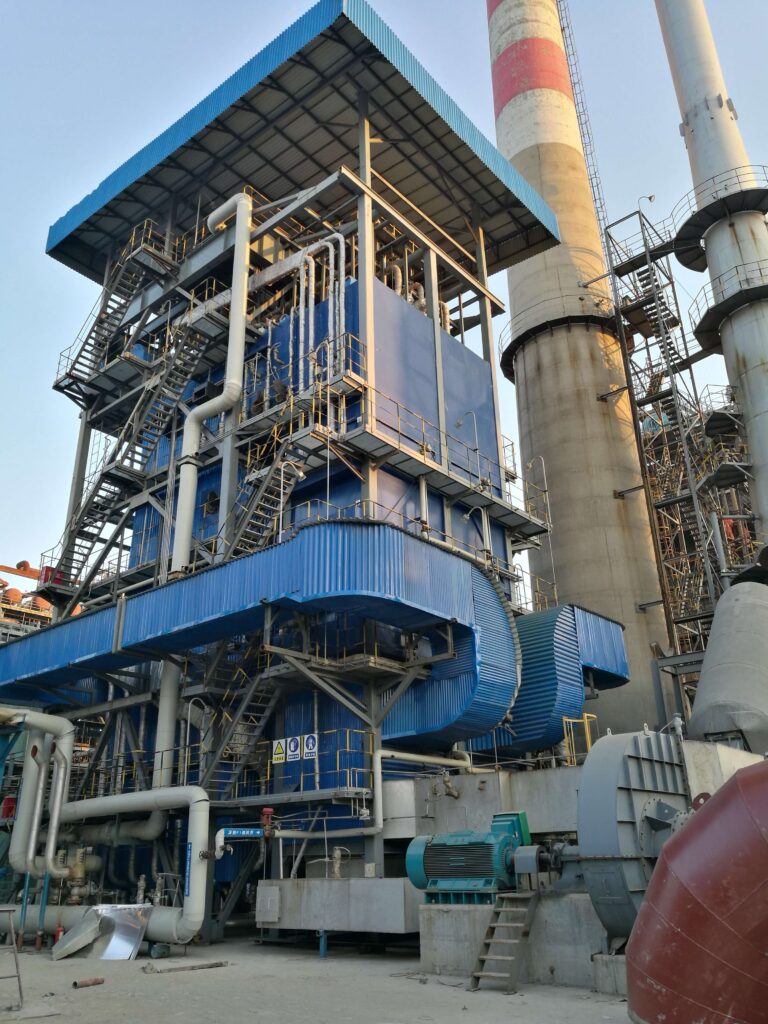
Correct industrial steam boiler sizing requires more than adding the rated steam consumption of every machine in a factory. The boiler must deliver enough steam at the required pressure and temperature during realistic peak production while remaining stable and efficient when demand falls.

An undersized boiler may cause pressure fluctuations, slow process heating, longer production cycles, and interruptions to production. Oversizing is not a risk-free solution. A boiler that operates far below its rated capacity for long periods may require unnecessary capital investment and incur higher standing losses. Gas- and oil-fired boilers may cycle frequently, while solid-fuel boilers may have difficulty maintaining efficient and stable combustion at very low loads.

The preliminary boiler capacity should be based on the maximum simultaneous process steam demand, plus calculated distribution losses, internal steam consumption, and a clearly defined design allowance.

Industrial Steam Boiler Sizing at a Glance

Required Boiler Capacity = Maximum Simultaneous Process Load + Distribution Losses + Internal Steam Use + Defined Design Allowance

Each component must have a clear calculation boundary. Loads that have already been calculated should not be counted again through an overlapping safety factor.

Engineering Note: This guide is intended for preliminary industrial steam boiler sizing. Final equipment selection must be verified using confirmed process loads, steam conditions, fuel data, feedwater conditions, site parameters, emission limits, and the applicable design code.

What Does Industrial Steam Boiler Size Mean?

Industrial steam boiler size normally refers to the quantity of steam a boiler can generate continuously under specified conditions. Capacity is commonly expressed in kilograms per hour, tonnes per hour, tonnes per hour of steam, or pounds per hour.

Boiler horsepower may appear in some North American specifications. One boiler horsepower is conventionally equal to 33,475 Btu/h, or the energy required to evaporate 34.5 lb/h of water “from and at” 212°F. It is a heat-output reference and should not be treated as a guarantee of actual steam production under every operating pressure and feedwater condition.

A boiler’s rated capacity is normally based on defined conditions such as steam pressure, steam temperature, feedwater temperature, design fuel, ambient temperature, and site altitude. A unit rated at 10 t/h under its design conditions may not maintain the same output if the actual fuel quality is substantially lower, the feedwater is colder, or the installation altitude is significantly higher than the design basis.

Several load definitions must also be distinguished.

The normal continuous load is the steam demand during stable routine production. The maximum simultaneous load is the highest realistic demand after determining which steam users actually operate at the same time. A short-duration peak may occur during equipment warm-up or batch startup but last for only a few minutes. The boiler’s maximum continuous rating, commonly called MCR, is the output it is designed to maintain continuously under specified conditions.

A short peak does not always justify permanently increasing boiler capacity. Depending on its frequency and duration, the peak may be managed by adjusting the production schedule, installing multiple boilers, improving system controls, or using a steam accumulator.

Step 1: Define the Required Steam Conditions

Steam quantity cannot be evaluated independently of pressure, temperature, and steam quality.

Confirm the Required Operating Pressure

The steam pressure required at the process equipment is not necessarily the pressure that must be produced at the boiler outlet.

Pressure is lost as steam passes through long pipelines, valves, separators, flowmeters, strainers, pressure-reducing stations, and other fittings. The loss also changes as steam flow changes.

For example, if production equipment requires 8 barg and the calculated distribution pressure loss is approximately 1 bar, the boiler may need to supply steam at about 9 barg or higher. The final value should be established from the actual steam-network design rather than by adding a standard pressure allowance.

Pressure specifications must identify whether the value is gauge or absolute:

  • barg means bar gauge, measured above atmospheric pressure.
  • bara means bar absolute, measured from an absolute vacuum.

At approximately sea-level atmospheric conditions, 8 barg is close to 9 bara. Writing only “8 bar” creates uncertainty when steam properties and design conditions are calculated.

Operating pressure should also be distinguished from design pressure. Boiler design pressure is determined according to the operating conditions, system-protection philosophy, applicable code, and required mechanical design margin. It is normally higher than the intended operating pressure.

Confirm Saturated or Superheated Steam

Saturated steam is widely used for industrial process heating because it releases substantial latent heat while condensing at an approximately constant temperature. Typical applications include jacketed vessels, process heat exchangers, textile equipment, food sterilizers, and paper dryers.

Superheated steam may be required for steam turbines, power generation, certain drying processes, or special high-temperature applications. It affects heating-surface arrangement, material selection, temperature control, thermal expansion, and piping design.

Steam enthalpy does not increase proportionally with pressure. Steam properties should therefore be obtained from recognized steam tables at the actual pressure and temperature. The NISTIR 5078 water and steam tables provide thermodynamic properties calculated from the IAPWS formulation.

Consider Steam Quality

Excessive moisture carried with the steam reduces the useful energy delivered per kilogram and may contribute to unstable process heating, water hammer, erosion, or damage to sensitive downstream equipment.

Steam quality is affected by boiler-water chemistry, water-level control, steam-space loading, steam separation, and sudden changes in demand. Required steam dryness should be confirmed for applications in which moisture carryover could affect process quality or equipment reliability.

Step 2: Calculate the Steam Demand of Each Process

An accurate boiler-sizing calculation begins with a complete schedule of all steam consumers.

The most reliable source is normally the equipment manufacturer’s stated normal and maximum steam demand. Actual flowmeter records from an operating plant are also valuable, provided that the measurement period represents the intended production rate.

When reliable consumption data are unavailable, the demand may be calculated from a process heat balance. Generic industry tables should be used only for early estimates because actual consumption depends on equipment size, production rate, initial temperature, target temperature, cycle time, steam pressure, and heat loss.

Indirect Steam Heating

For an indirect heat exchanger or jacketed vessel, the preliminary steam demand can be calculated as follows:

Required steam flow, kg/h = Process heat demand, kJ/h ÷ Useful enthalpy difference, kJ/kg

The useful enthalpy difference is:

Steam inlet enthalpy − Condensate outlet enthalpy

For example:

Steam flow = Q ÷ (h steam inlet − h condensate outlet)

Where:

  • Q is the process heat demand in kJ/h.
  • h steam inlet is the specific enthalpy of the steam entering the equipment.
  • h condensate outlet is the specific enthalpy of the condensate leaving the equipment.

If the process duty is stated in kW:

1 kW = 3,600 kJ/h

The steam and condensate enthalpies must correspond to their actual conditions. Boiler feedwater enthalpy should not automatically be substituted for condensate outlet enthalpy. Feedwater temperature is important when calculating boiler heat input and fuel consumption, but it may not represent the condition of condensate leaving a process heat exchanger.

Direct Steam Injection

Direct steam injection must be calculated separately because the steam becomes part of the process material.

Common applications include cooking, humidification, deaeration, tank heating, steam stripping, process-water heating, cleaning, and purging. The calculation must account for the process mass balance, initial and final temperatures, operating pressure, and allowable product moisture.

It should not be calculated using the same condensate-return assumptions as an indirect heat exchanger.

Example Steam-Consumer Schedule

The following figures are illustrative and show how the information may be organized for a food-processing plant.

Steam ConsumerNormal LoadMaximum LoadPeak DurationRequired PressureOperating Pattern
Continuous production line3,000 kg/h3,000 kg/hContinuous8 bargFull production shift
Batch sterilizer0 kg/h900 kg/h20 minutes8 bargSeveral cycles per shift
Deaerator and internal use150 kg/h150 kg/hContinuousSystem pressureWhile the boiler operates
Distribution systemCalculated separately250 kg/hContinuous estimateBased on the pipe network

A real project should replace these illustrative figures with equipment data, measured consumption, or a verified heat balance.

Step 3: Determine the Maximum Simultaneous Process Load

Adding every equipment nameplate value may produce an unrealistically high result. Using average daily consumption can create the opposite problem and underestimate the required peak output.

The correct calculation must identify which loads operate at the same time.

Suppose five batch vessels each have a maximum steam demand of 500 kg/h. Their combined nameplate demand is 2,500 kg/h. If the confirmed production schedule allows no more than three vessels to heat simultaneously, the realistic batch peak may be approximately:

3 × 500 kg/h = 1,500 kg/h

This adjustment should only be made when supported by production schedules, batch records, flowmeter data, equipment interlocks, or confirmed operating procedures. A simultaneity factor should not be selected simply to obtain a smaller boiler.

Continuous, batch, startup, and emergency loads should also be separated. A continuous production line establishes the base load, while a sterilizer or reactor may create a high but temporary demand. Emergency equipment should only be added to normal production when the operating philosophy genuinely requires simultaneous use.

An hourly or 15-minute load profile is especially valuable for food processing, textile dyeing, rubber manufacturing, pharmaceuticals, breweries, and chemical plants. In these industries, the maximum steam demand may be substantially higher than the daily average.

For example, a plant consuming 48 tonnes of steam per day does not necessarily require only a 2 t/h boiler. Dividing 48 tonnes by 24 hours gives the average consumption, but the plant may still experience a 4 t/h or 5 t/h demand during production startup.

Step 4: Account for Distribution Losses and Internal Steam Use

Steam losses should be evaluated by category instead of represented by an unexplained standard percentage.

Distribution Heat Loss

Heat loss from steam pipelines depends on pipe length, pipe diameter, steam condition, insulation material, insulation thickness, ambient temperature, wind exposure, and whether the line is installed indoors or outdoors.

A new and well-insulated steam network may have relatively limited heat loss. A long outdoor main with damaged insulation, exposed valves, and numerous branches may lose considerably more.

Distribution loss should therefore be estimated from the actual steam-network layout and insulation condition rather than automatically set at 5% or 10%.

Leakage and Steam-Trap Losses

Steam may be lost through leaking valves, damaged flange joints, failed steam traps, open bypasses, or uncontrolled venting.

Known maintenance defects should normally be repaired rather than treated as permanent design loads. Selecting a larger boiler to compensate for avoidable leakage increases capital cost while allowing the underlying energy loss to continue.

Blowdown and Internal Steam Consumption

Boiler blowdown is required to control dissolved and suspended solids in boiler water. It removes hot water from the system and affects feedwater demand, fuel consumption, water treatment, and the overall heat balance.

Internal steam consumers may include deaerator heating, fuel-oil atomization, soot blowing, steam tracing, and steam-driven auxiliaries. These uses reduce the quantity of steam available to production and should be included separately.

The U.S. Department of Energy’s industrial steam-system resources address generation, distribution, end use, blowdown, steam traps, and condensate return as connected parts of one steam system.

Step 5: Separate Startup Loads From Normal Production

Steam demand during startup can differ significantly from the normal operating load.

Process equipment, pipelines, tanks, heat exchangers, and product may all require heating from their initial temperature to the required operating temperature. The warm-up demand depends on the heated mass, specific heat, temperature rise, heat loss, and permitted warm-up time.

A high warm-up demand that lasts for 20 minutes should not automatically be treated as a continuous 24-hour load. Its duration and frequency must be recorded.

The boiler’s own cold-start energy should also be treated separately. Heating the boiler water, pressure parts, refractory, and connected piping primarily affects startup fuel use, ramp rate, and the time required before steam becomes available. It is not normally an external process steam consumer expressed in kg/h.

It only becomes a separate steam load when another boiler or external steam source provides startup steam to the new unit or its auxiliary system.

Managing a Short-Term Peak

A temporary peak may be addressed by increasing boiler capacity, installing multiple boilers, staggering equipment startup, or using a steam accumulator.

A steam accumulator stores most of its usable thermal energy in pressurized hot water. When the pressure falls, part of the stored water flashes into steam and supports the temporary demand. This can be more appropriate than permanently oversizing a boiler when the peak is high but short.

The Spirax Sarco steam accumulator guide explains the relationship between pressurized water, pressure reduction, and flash-steam release.

Step 6: Add a Design Allowance Without Double Counting

A design allowance should cover justified uncertainty that has not already been included in the calculation.

Possible sources of uncertainty include incomplete early-stage equipment data, measurement tolerance, moderate operating variation, or a near-term change that cannot yet be quantified accurately.

The allowance should not repeat requirements already entered separately.

For example, if the calculation already includes the maximum batch peak, pipeline loss, internal steam consumption, and a confirmed future production line, another general percentage should not be added to cover those same items again.

There is no universal safety margin that is correct for every industrial steam system. A stable plant with reliable flowmeter records may justify a relatively small allowance. A new batch-processing plant with incomplete equipment data requires a more detailed uncertainty assessment.

Where future expansion equipment is known, its expected steam demand should be included as an actual load rather than hidden inside a broad percentage.

Step 7: Calculate the Preliminary Boiler Capacity

The basic sizing structure is:

Required Boiler Capacity = Maximum Simultaneous Process Load + Distribution Losses + Internal Steam Use + Defined Design Allowance

The following example uses hypothetical figures and demonstrates the calculation method only.

Worked Industrial Steam Boiler Sizing Example

A food-processing plant has a continuous process demand of 3,000 kg/h. Its batch sterilizer has a maximum steam demand of 900 kg/h, but the production schedule indicates that 70% of the batch rating should be included in the maximum simultaneous condition.

Internal steam use is estimated at 150 kg/h, and calculated distribution loss is 250 kg/h.

For preliminary evaluation, an 8% uncertainty allowance is accepted. In this illustrative example, it is applied to the subtotal because all input values retain a small degree of overall uncertainty. In an actual project, the allowance should be applied only to components that remain uncertain.

Step 1: Calculate the Simultaneous Batch Load

900 kg/h × 70% = 630 kg/h

Step 2: Calculate the Maximum Simultaneous Process Load

3,000 kg/h + 630 kg/h = 3,630 kg/h

Step 3: Add Internal Use and Distribution Losses

3,630 kg/h + 150 kg/h + 250 kg/h = 4,030 kg/h

Step 4: Calculate the Uncertainty Allowance

4,030 kg/h × 8% = 322 kg/h

Step 5: Calculate the Preliminary Requirement

4,030 kg/h + 322 kg/h = 4,352 kg/h

The preliminary boiler requirement is therefore approximately:

4.35 t/h

A nominal 5 t/h boiler may be evaluated, provided that the manufacturer can guarantee the required net steam output under the specified pressure, feedwater temperature, fuel quality, altitude, and ambient conditions.

A staged multi-boiler configuration may also be considered using suitable standard capacities. The final arrangement depends on minimum plant demand, peak duration, maintenance requirements, available space, investment, and the required standby philosophy.

The example does not mean that every calculated requirement of approximately 4.35 t/h should automatically use the same configuration.

Step 8: Choose Between One Boiler and Multiple Boilers

A single boiler generally involves simpler controls, fewer valves, less installation space, and lower initial system cost. It may be suitable when the load is stable, planned production shutdowns are acceptable, and full standby capacity is not required.

Multiple boilers may be preferable when demand changes substantially between shifts or seasons, when the minimum load is far below the maximum load, or when partial steam supply must remain available during maintenance.

With an appropriate sequencing strategy, one unit can operate during low-demand periods and additional capacity can be brought online as production demand rises. This may keep operating boilers closer to a suitable load range.

Multiple units do not automatically provide full redundancy. If all installed units are required to satisfy maximum production demand, losing one unit will reduce the available output.

Full N+1 redundancy means the required demand can still be met after one unit becomes unavailable. It may be justified for critical chemical processes, hospitals, or plants where a steam interruption creates a major safety or production risk. It should not be specified automatically without comparing the additional investment with the potential cost of downtime.

Examples From Published Taishan Group Projects

Taishan Group’s published references show that industrial steam requirements can lead to very different capacities and boiler configurations.

A textile project for Utopia Industries in Pakistan uses a 20 TPH coal-fired steam boiler. A beverage EPC project in Thailand includes two 30 TPH spent-grain biomass boilers and a 9 MW backpressure steam turbine-generator system. An EPC project in Uruguay includes one 4 t/h HFO boiler and one 4 t/h wood-chip biomass steam boiler. (Taishan Group)

These references confirm the published boiler capacities, fuel types, and project applications. The project page does not disclose the underlying load profiles, simultaneity factors, minimum-load calculations, or redundancy criteria. They should therefore not be treated as universal sizing benchmarks.

The practical lesson is that textile production, beverage manufacturing, and mixed-fuel industrial facilities can require very different solutions. Final boiler capacity must be based on the specific process and operating conditions of each project.

More verified references are available on the Taishan Group Project Case page.

Step 9: Check the Minimum Stable Load

Maximum capacity is only one side of boiler sizing. The selected system must also operate acceptably when plant demand is low.

For an oil- or gas-fired boiler, low-load performance is influenced by burner modulation, combustion stability, excess-air control, boiler water volume, control settings, and the relationship between minimum burner output and plant demand.

For a coal-fired boiler or biomass boiler, minimum load also depends on fuel-bed stability, grate loading, fuel moisture, furnace temperature, and airflow distribution. A turndown ratio quoted for a gas burner should not be applied directly to a solid-fuel grate boiler.

For a circulating fluidized bed boiler, stable operation is influenced by bed temperature, fluidization conditions, solids circulation, fuel characteristics, and emission requirements.

There is no universal turndown ratio for all industrial boilers. The manufacturer should confirm the guaranteed operating range for the proposed boiler design and specified fuel.

Step 10: Verify Fuel, Feedwater, and Site Conditions

Fuel type does not change the process steam requirement, but it strongly affects whether the boiler can reliably achieve its rated output.

For coal and biomass projects, the manufacturer generally needs a representative fuel analysis. Important information includes lower heating value, moisture, ash, volatile matter, sulfur and chlorine where relevant, ash-fusion characteristics, particle-size distribution, bulk density, and expected fuel variation.

A description such as “wood chips” or “local coal” is not sufficient for final design because fuels with the same general name can have substantially different combustion properties.

For gas-fired projects, required information includes gas composition or heating value, available inlet pressure, minimum and maximum supply pressure, gas temperature, and any required backup fuel.

Feedwater temperature affects the energy required to generate steam. Returning hot condensate can reduce fuel consumption, makeup-water demand, chemical-treatment demand, and wastewater discharge. It does not normally reduce the mass of steam required by the production process. The U.S. Department of Energy notes that condensate return reduces energy requirements because returned condensate is already hot. (energy.gov)

Site altitude and ambient temperature can affect combustion-air density, fan selection, burner performance, and electrical equipment. Final project data should therefore include the installation location, altitude, ambient-temperature range, humidity, and power supply.

Local emission limits must also be confirmed before the boiler and auxiliary systems are finalized. They may affect furnace design, burner configuration, particulate control, desulfurization, denitrification, stack design, electrical load, and the overall plant layout.

Common Industrial Steam Boiler Sizing Mistakes

Common MistakeWhy It Creates a Problem
Dividing daily steam use by 24 hoursThis produces an average load rather than the maximum simultaneous demand.
Adding every equipment nameplate loadThis may oversize the boiler when equipment does not operate simultaneously.
Applying several overlapping marginsPeak load, losses, internal use, startup demand, and expansion may be counted more than once.
Dividing steam demand by boiler efficiencyEfficiency determines required fuel input, not the process steam-flow requirement.
Ignoring the minimum plant loadThe boiler may satisfy maximum demand but perform poorly during low production.
Treating condensate return as reduced steam demandCondensate return reduces energy and water consumption but normally not process steam mass flow.
Ignoring steam-line pressure lossThe required pressure may not be available at the production equipment.
Writing pressure without barg or baraSteam-property and design calculations may use the wrong pressure basis.

Information Required for Final Boiler Sizing

A final technical proposal should be based on verified process, fuel, and site data rather than a single requested capacity.

CategoryInformation Required
Steam demandNormal demand, maximum simultaneous demand, minimum load, peak duration, and peak frequency
Operating scheduleHours per day, shifts, days per year, and batch schedule
Steam conditionsBoiler outlet pressure, process inlet pressure, saturated or superheated steam, and required temperature
FuelFuel type, heating value, analysis, moisture, ash, particle size, or available gas pressure
FeedwaterInlet temperature, water analysis, condensate-return rate, and makeup-water source
SiteCountry, altitude, ambient-temperature range, humidity, and installation space
Electrical supplyVoltage, phase, frequency, and available electrical capacity
Environmental requirementsApplicable particulate, SO₂, NOx, CO, and other emission limits
Design requirementsApplicable boiler code, inspection requirements, and required certification
ReliabilitySingle unit, multiple units, standby capacity, or N+1 requirement
Project scopeBoiler only, complete boiler island, auxiliaries, erection, commissioning, or EPC
Future expansionIdentified future equipment and its calculated steam requirement

Final Boiler Sizing Checklist

Before confirming the proposed capacity, verify that:

  • All process and internal steam consumers have been identified.
  • The maximum simultaneous demand is based on a realistic operating schedule.
  • Peak duration and frequency are known.
  • Startup loads are separated from continuous production loads.
  • Distribution losses are calculated or reasonably estimated.
  • The design allowance has been applied only once.
  • The minimum plant load has been compared with the boiler’s operating range.
  • Steam pressure, steam temperature, barg, and bara are clearly defined.
  • Fuel, feedwater, altitude, ambient conditions, and emissions are confirmed.
  • Single-unit, multiple-unit, and standby arrangements have been compared.
  • The proposed boiler can guarantee the required output under actual project conditions.

Conclusion

Industrial steam boiler sizing should begin with the maximum realistic simultaneous process load, not average daily consumption and not the simple sum of all equipment nameplate values.

Distribution loss, internal steam use, startup demand, future expansion, and design uncertainty should be evaluated separately. This prevents the same load from being counted more than once and reduces the risk of unnecessary oversizing.

The final boiler configuration must also match the plant’s minimum demand, steam pressure, fuel quality, feedwater temperature, site conditions, emission requirements, and reliability objectives.

Send us your steam-consumer data, required pressure, fuel information, and operating schedule. Taishan Group can review the preliminary boiler capacity and identify the additional information required for final selection.

Frequently Asked Questions

How is industrial steam boiler capacity calculated?

Preliminary capacity is calculated by adding the maximum simultaneous process demand, distribution losses, internal steam use, and a justified design allowance. Peak duration, minimum load, steam pressure, fuel conditions, and the required standby arrangement must also be evaluated before final selection.

How much spare boiler capacity should be added?

There is no universal percentage for every project. The allowance should cover only uncertainty that has not already been included. Known distribution losses, calculated startup demand, internal use, and confirmed future expansion should not be counted again through another general safety factor.

Should boiler capacity be based on average or peak steam demand?

Capacity should normally be based on a realistic maximum simultaneous demand. However, the duration and frequency of the peak are also important. A brief peak may sometimes be handled by process scheduling, multiple boilers, control changes, or a steam accumulator.

Is one large boiler better than two smaller boilers?

A single boiler is normally simpler and may require less initial investment. Multiple boilers can improve load matching, maintenance flexibility, and partial availability. The appropriate arrangement depends on minimum demand, seasonal variation, available space, downtime risk, and standby requirements.

Does a biomass boiler need a higher t/h rating than a gas-fired boiler?

Not solely because it burns biomass. If the process requires 10 t/h of steam, the required process output remains 10 t/h. Fuel characteristics affect furnace design, combustion equipment, fuel consumption, emission control, and the conditions under which the manufacturer can guarantee the rated output.

References

Thermodynamic Properties of Water: NISTIR 5078

Water and steam property tables calculated from the IAPWS formulation, including saturation and superheated-steam data.

Steam Systems — U.S. Department of Energy

Technical resources covering industrial steam generation, distribution, steam traps, blowdown, condensate return, and system optimization.

Improving Steam System Performance: A Sourcebook for Industry

A systems-based industrial steam reference covering boiler generation, distribution, end use, recovery, and assessment tools.

Best Management Practice: Steam Boiler Systems

DOE guidance covering condensate recovery, water management, blowdown control, and steam-boiler system efficiency.

Steam Accumulators

Technical guidance explaining accumulator charging, pressure reduction, flash-steam production, peak demand, and load leveling.

Taishan Group Project Cases

Published Taishan Group boiler references covering different capacities, fuels, industries, and project configurations.

Industrial Steam Boiler Sizing: Capacity Calculation Guide Read More »
What Capacity and Size of waste heat recovery boiler Do You Need?

Sizing a waste heat recovery boiler wrong is one of those mistakes that looks minor on a datasheet and catastrophic on the energy bill. Undersized units leave recoverable enthalpy venting straight to atmosphere — sometimes 2–5 MW of thermal energy just gone, depending on the process. Oversized units create partial-load condensation problems, accelerated corrosion in the economizer section, and capital tied up in steel that never earns its keep. Either way, the plant pays.

A waste heat recovery boiler should be sized to match the actual flue gas flow rate, inlet temperature, and required steam parameters of your specific process. Steam output typically ranges from 1 t/h to 130 t/h, with inlet flue gas temperatures anywhere from 300°C to 1,100°C depending on the heat source. Getting those three inputs right — flow, temperature, and end-use steam pressure — determines everything else about the unit’s physical size and configuration.

What makes this genuinely tricky is that the “right” capacity isn’t a fixed number you look up in a table. It shifts with your process load profile, whether you need saturated or superheated steam, how many tail-end surfaces you’re willing to pay for, and what your stack temperature limit is for corrosion control. The next sections work through each of those variables in the order that actually matters for selection.

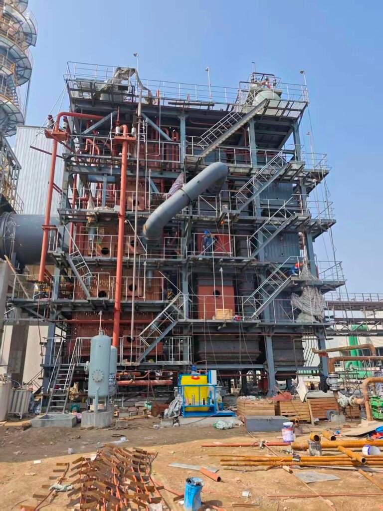
Large industrial waste heat recovery boiler installed in a cement plant, showing flue gas ducting and steam drum

Auditing Your Heat Source: Flue Gas Flow, Temperature, and Composition Before Anything Else

Before you specify a single tube diameter or drum pressure, you need three numbers from your process: how much gas is flowing, how hot it is, and what’s in it. Skip that audit — or rely on guesswork from a similar plant — and you’ll either build a boiler that starves for heat half the year or one that clogs, corrodes, and trips offline every few months. Both outcomes are expensive. The audit itself costs almost nothing compared to a redesign after fabrication.

Volumetric Flow Rate: Nm³/h vs. Actual m³/h

Always specify flow at normal conditions (0°C, 101.325 kPa) — that’s Nm³/h — not at the actual gas temperature. A cement kiln exit stream at 350°C that measures 80,000 actual m³/h is only around 47,000–52,000 Nm³/h once you correct for temperature, and that difference directly changes the heat exchanger surface area your supplier will calculate. Confusing the two is one of the more common errors I see in enquiry documents from first-time WHRB buyers.

If no flow meter exists on your exhaust duct — and on older plants, they often don’t — you can back-calculate from mass balance: fuel consumption rate × stoichiometric air factor × (1 + excess air coefficient α) gives you a reasonable working estimate of flue gas mass flow, which you then convert using the mixture’s molecular weight and density. It’s not as clean as a Pitot traverse measurement, but for initial sizing it’s usually within 8–12% depending on how well the fuel composition is known.

Inlet and Outlet Temperature Targets

Inlet temperature drives the duty calculation directly. The range is wide in practice — gas turbine exhaust typically runs 450–560°C, while a copper smelter reverberatory furnace can push 900–1,100°C, requiring a radiation chamber ahead of any convective surface just to protect the tubes. Your outlet target temperature (the flue gas temperature leaving the WHRB) is equally important and is often set not by thermodynamics but by corrosion constraints.

The Dew-Point Problem with Sulfurous Gases

Flue gas from sulfuric acid plants and copper smelters can cause rapid cold-end corrosion if economizer surface temperatures drop below 160°CTrue

High SO₂ concentrations convert to SO₃ in the presence of catalytic surfaces and moisture; SO₃ combines with water vapor to form sulfuric acid vapor with a dew point typically between 130–180°C depending on SO₃ partial pressure. Allowing metal wall temperatures to fall below this dew point causes rapid acid condensation and pitting corrosion on economizer fins and tube banks.

For any source with SO₂ above roughly 500 mg/Nm³, set your minimum flue gas exit temperature at 160–180°C — the exact floor depends on SO₃ concentration and moisture content, so run the acid dew-point calculation before finalizing tube material selection. Low-alloy steels like 20G will fail within one or two seasons at sub-dew-point wall temperatures. Corten or 09CrCuSb (ND steel) adds maybe 15–25% to economizer material cost but buys years of service life. Worth it every time.

Dust Loading Dictates Layout, Not Just Cleaning Frequency

Dust content in g/Nm³ shapes the entire boiler configuration.

Heat SourceTypical Inlet Temp (°C)Dust Loading (g/Nm³)Layout Implication
Gas turbine exhaust450–560< 0.1Compact convective HRSG, tight fin pitch acceptable
Diesel engine exhaust350–480< 0.5Convective only; watch for oil mist fouling
Cement kiln preheater exit300–38020–80Radiation chamber + settling hopper mandatory; wide tube pitch
Glass furnace regenerator exit400–5502–8Convective with soot blowers; check alkali vapor condensation
Electric arc furnace (EAF) offgas600–1,00015–60Forced-flow radiation section; heavy-duty hoppers and rapping gear
Sulfuric acid converter exit420–6001.4, common in some glass [furnaces](https://coalbiomassboiler.com/product/boiler-auxiliaries/ “furnaces”) running air-rich for process reasons) dilutes the gas enthalpy per Nm³ and you need more surface to recover the same megawatts. Free O₂ above roughly 10% also accelerates oxidation on bare carbon-steel surfaces at temperatures above 550°C, which nudges you toward alloy tube materials sooner than you might expect.

Get these measurements — or at minimum credible estimates with stated assumptions — documented before you send an enquiry to any boiler manufacturer. A reputable supplier will ask for all of them anyway. If they don’t, that itself tells you something.

Calculating Required Heat Absorption: The Core Sizing Equation Explained Step by Step

Before you can trust any vendor’s proposal, you need to run the heat balance yourself. It’s not complicated, but skipping it is how plants end up with a boiler that’s 30% undersized or one that can never reach design steam output because the economizer is steaming in summer.

The Fundamental Heat Balance

The starting equation is:

Q = ṁ_gas × Cp_gas × (T_in − T_out) × η_recovery

Where Q is recoverable heat (kW or kcal/h), ṁ_gas is the flue gas mass flow rate (kg/s or kg/h), Cp_gas is the specific heat of the flue gas mixture (roughly 1.05–1.15 kJ/kg·°C for most combustion exhaust, higher if CO₂-rich, lower if diluted with excess air), T_in and T_out are the inlet and target outlet flue gas temperatures, and η_recovery accounts for heat loss through casing radiation and incomplete surface utilization — typically 0.88–0.94 on a well-insulated unit.

Worked example: a cement kiln bypass exhaust at 55,000 Nm³/h, 520°C inlet, targeting 180°C outlet. Convert volumetric to mass flow using the actual flue gas density (around 0.38–0.42 kg/Nm³ at that temperature — check your gas composition). Call it 0.40 kg/Nm³, so ṁ_gas ≈ 22,000 kg/h. With Cp_gas = 1.08 kJ/kg·°C and η = 0.91:

Q = 22,000 × 1.08 × (520 − 180) × 0.91 ≈ 7,370 kW (roughly 6.34 Gcal/h)

That number is your design anchor. Everything else — tube surface area, drum sizing, circulation ratio — derives from it.

Converting Q to Steam Output

Once you have Q, steam output D (t/h) follows from:

Q = D × (h_steam − h_feedwater)

Enthalpy values come straight from steam tables. At 1.6 MPa saturated, h_steam ≈ 2,794 kJ/kg; at 3.82 MPa with 10°C superheat, h_steam ≈ 2,800 kJ/kg; at 9.8 MPa with 480°C superheat, h_steam ≈ 3,386 kJ/kg. Feedwater enthalpy depends on deaerator temperature — commonly 104°C, giving h_fw ≈ 436 kJ/kg.

Using the example above (Q = 7,370 kW = 26,532 MJ/h) at 3.82 MPa:

D = 26,532 / (2,800 − 436) ≈ 11.2 t/h

A vendor quoting 13 t/h from the same gas stream should be asked to show their enthalpy assumptions. Usually they’ve used optimistic outlet temperature or ignored duct heat loss.

Choosing Your Outlet Flue Gas Temperature

This is where engineers make or break the economics. Push T_out too low and you recover more heat — but risk sulfuric acid condensation on the cold-end economizer tubes, which destroys them within one to two heating seasons. Push it too high and you’re leaving recoverable energy in the stack.

Typical targets: 160–200°C for exhaust containing sulfur (diesel generators, sulfur-bearing coal, some waste gases); 120–140°C for clean natural gas exhaust. If your fuel or process gas varies in sulfur content seasonally — and in many plants it does — design to the worst-case dew point with a 15–20°C margin, not the average.

Pinch Point and Why It Controls Physical Size

The pinch point is the minimum temperature difference between the flue gas and the saturation temperature of steam at a given cross-section inside the boiler. Industry standard for WHRBs is 15–25°C. Go below 15°C and you need disproportionately more heat transfer surface — cost rises steeply, and there’s real risk of subcooled boiling in the economizer, which causes flow instability. Go above 25°C and you’re simply leaving recovery on the table.

Approach temperature (between economizer outlet water and saturation temperature) should stay at least 10–15°C to prevent steaming in the economizer at partial load — a condition that accelerates tube erosion and makes the drum level control behave erratically.

Superheater Section: When You Need It and What It Costs

If steam drives a turbine or a process that specifies minimum superheat, you need a dedicated superheater bank upstream of the evaporator section (higher gas temperature side). Tubes here see both high temperature and steam-side oxidation, so material typically steps up to 12Cr1MoV or TP304H, depending on steam temperature. That change alone can add 15–30% to tube bundle material cost and push lead time out by 6–10 weeks compared to a saturated steam unit.

Indicative Sizing Table

Flue Gas Flow (Nm³/h)Inlet Temp (°C)Outlet Temp (°C)Steam Output at 1.6 MPa (t/h)Steam Output at 3.82 MPa (t/h)Steam Output at 9.8 MPa (t/h)
10,000500180~2.0–2.4~1.9–2.3~1.6–2.0
30,000500180~6.0–7.2~5.8–6.9~5.0–6.0
55,000520180~11–13~10–12~8.5–10
80,000500180~16–19~15–18~13–15

Ranges reflect variation in Cp_gas, feedwater temperature (95–130°C), and casing loss assumptions. A gas with high CO₂ or water vapor content will shift values upward; highly diluted exhaust (excess air > 200%) shifts them down noticeably.

Running the heat balance before issuing an RFQ gives procurement teams an independent check on vendor steam output claims and prevents over-specification that inflates capital cost.True

The Q = ṁ × Cp × ΔT × η equation is standard thermodynamic accounting used in WHRB engineering practice; enthalpy-based steam output conversion is directly verifiable against published steam tables and gives buyers a quantitative benchmark independent of vendor assumptions.

Run these numbers before you open the bidding process. Vendors who can’t reconcile their proposal with your heat balance — with transparent assumptions — are a red flag.

Selecting Steam Pressure and Temperature to Match Your Process or Power Generation Requirement

Pressure and temperature aren’t just boiler specs — they define the entire mechanical design, the applicable pressure vessel code, your inspection and certification timeline, and ultimately what the steam can actually do once it leaves the drum. Getting this decision wrong late in a project is expensive. Getting it wrong early is just an engineering error you can fix on paper.

Low-Pressure Saturated Steam (0.4–1.6 MPa)

This is the workhorse range for most process industries: food and beverage sterilization, timber drying, rubber vulcanization, general plant heating. At these pressures, saturated steam is usually all you need. The boiler design stays relatively simple — natural circulation works reliably, drum wall thickness stays manageable, and you don’t need a superheater section at all. Fabrication and inspection costs are lower, lead times are shorter, and your operators have a less demanding certification requirement in most jurisdictions.

One practical point: if your waste heat source comes in below roughly 400°C, you may struggle to justify a superheater anyway, because the temperature differential across the superheating surface shrinks and the added surface area delivers diminishing returns. At that point, a natural-circulation saturated steam WHRB at 0.8–1.0 MPa is often the right call.

Medium-Pressure Steam (1.6–5.3 MPa)

Once you’re driving a backpressure turbine for CHP, feeding an absorption chiller, or supplying refinery process requirements, you’re in medium-pressure territory. Superheated steam becomes necessary here — not just for efficiency, but because saturated steam entering a turbine causes blade erosion within months. Expect to add a superheater section and, depending on flue gas temperature and mass flow, possibly a forced-circulation design review. Natural circulation is still often feasible at the lower end of this range, but your thermal hydraulics engineer needs to verify it, not assume it.

The absorption chiller case is worth flagging specifically: many plant engineers specify 0.8 MPa for an absorption chiller when the machine actually calls for 0.6–0.7 MPa. That gap seems trivial until you’re throttling steam constantly and wondering why your chiller COP is drifting.

High-Pressure Steam (5.3–9.8 MPa)

At these pressures — typically for condensing or extraction turbines exporting power to the grid — the boiler design changes substantially. Drum walls thicken, materials move into higher-grade alloy territory, and natural circulation becomes increasingly marginal above roughly 7 MPa, depending on boiler height and circulation ratio. Forced circulation or once-through designs are common. Critically, this pressure range triggers the most demanding regulatory tier in every major code: Class A boiler certification under China’s GB/T 16507 and TSG G0001, ASME Section I for North American and many Middle Eastern projects, or PED Category IV under EU Directive 2014/68/EU. Inspection hold points multiply, third-party witness requirements apply, and material traceability documentation becomes non-negotiable. Budget the extra time — in my experience, moving from a medium-pressure design to a high-pressure design can add 8–14 weeks to a project schedule, depending on the certifying body’s workload.

Hot Water WHRB: The Overlooked Alternative

When your end use is district heating, process water circuits, or building HVAC, you don’t need steam at all. A hot water waste heat boiler with an outlet temperature of 95–150°C eliminates the steam drum, the steam certification requirement, and the operational complexity of blowdown management and steam trapping. Regulatory burden drops noticeably — hot water boilers below certain pressure-temperature thresholds fall outside the heaviest inspection tiers in most codes. Operators with less steam experience also tend to run them more reliably.

The tradeoff is heat transfer distance. Hot water systems need adequate pump sizing and pipe insulation to maintain temperature over long runs. For a compact single-building plant, this is rarely a problem.

Thermal Oil WHRB: High Temperature Without High Pressure

Some processes genuinely need 250–320°C heat delivery but can’t tolerate the steam pressure that would correspond to those saturation temperatures — roughly 4–11 MPa. Asphalt plants, bitumen storage, certain chemical reactors, and some textile operations fall into this category. A thermal oil (heat transfer fluid) WHRB circulates a synthetic or mineral oil through the coil circuit instead of water, delivering high-temperature heat at near-atmospheric system pressure.

Thermal oil WHRBs operate under the same pressure vessel codes as steam boilers of equivalent pressure rating.False

Thermal oil boilers are governed by separate standards — for example, GB/T 17410 in China and EN 13445 in Europe — because the fluid properties, fire risk classification, and coil design requirements differ fundamentally from water-tube or shell-and-tube steam boiler standards. An engineer specifying a thermal oil unit needs to confirm the applicable fluid heater standard, not default to the steam boiler code.

Construction standards, coil geometry, fluid velocity requirements, and fire safety classifications are all different from steam boiler work. Specify the two as separate packages. Don’t let a procurement team consolidate them under one steam boiler spec sheet.

Pressure Vessel Code Selection for Export Projects

The code you specify locks in your material procurement, your welding procedure qualifications, your NDE requirements, and your authorized inspection body. For projects destined for North America or many parts of the Middle East, ASME Section I is essentially the default, and it requires an ASME-authorized inspection agency present at the shop. European projects typically require EN 12952 (water-tube) with CE marking under PED. China-origin boilers built to GB/T 16507 can be adapted for export, but the adaptation process — including third-party review of design documents to ASME or EN standards — takes time and adds cost that needs to be in the budget from day one, not discovered during submittal review.

A compact comparison:

CodePrimary MarketKey TriggerTypical Impact on Lead Time
ASME Sec. INorth America, Middle EastAny fired pressure vessel for steam+4–10 weeks vs. GB build
EN 12952 / PEDEuropeExport to EU member states+4–8 weeks; notified body required
GB/T 16507 / TSGChina domesticStandard for China-manufactureBaseline
Local adaptationOther export marketsVaries by country AHJConfirm early — can be 12+ weeks

Confirm the applicable code before the thermal design is frozen. Changing codes mid-design isn’t impossible, but it usually means requalifying weld procedures, re-sourcing some pressure-part materials, and, occasionally, redesigning the drum entirely.

Physical Configuration and Layout: Fire-Tube vs. Water-Tube and How Dust Loading Decides

The structural choice between fire-tube and water-tube isn’t academic — get it wrong and you’re either over-spending on a water-tube unit for a clean, low-volume gas stream, or you’re watching a fire-tube unit choke on dust-laden kiln off-gas within the first operating season.

Fire-Tube (Shell-and-Tube) WHRB

In a fire-tube design, hot flue gas passes through tubes submerged in the water/steam-filled shell. Simple to fabricate, compact, and relatively inexpensive — a unit in the 2–8 t/h range can be shop-assembled and shipped as a single piece, which procurement teams tend to appreciate when site access is tight.

The practical ceiling is roughly 600°C inlet gas temperature. Push beyond that and you’re stressing tube-to-tubesheet joints, and thermal fatigue becomes a maintenance headache inside two or three years. Capacity is realistically limited to about 10 t/h; anything larger gets physically unwieldy in shell form. Dust loading is the other hard constraint. Even moderate particulate concentrations — say, above 2–3 g/Nm³ — cause tube-side fouling that’s genuinely difficult to clean because you can’t easily access the inside of hundreds of small-bore tubes. Fire-tube WHRBs belong on clean gas sources: engine exhaust, natural-gas furnace flue gas, some chemical process off-gases where the stream has already been de-dusted upstream.

Water-Tube WHRB

Flip the arrangement — water and steam inside the tubes, hot gas flowing across the outside — and almost everything changes. You can handle inlet temperatures up to 1,100°C with proper front-end design, accommodate heavy dust loading because the gas-side surface is accessible for cleaning, and scale capacity up to 130 t/h or beyond. Water-tube units dominate cement kilns, electric arc furnaces, non-ferrous smelters, and glass tanks for exactly these reasons.

The trade-off is cost and complexity. A water-tube WHRB requires a proper steam drum, circulation system (natural or forced, depending on pressure and geometry), and more sophisticated engineering for tube bundle arrangement. But for anything above roughly 10 t/h or above 600°C inlet, it’s not really a choice — it’s the only sensible option.

waste-heat-recovery-boiler-capacity-size-01-water-tube-vs-fire-tube-whrb-configuration-diagram

Radiation Chamber: Non-Negotiable Above 700°C

When inlet gas comes in above roughly 700°C — typical for electric arc furnace off-gas, copper flash smelting, or certain glass furnace exhausts — a bare convection bank will overheat. The radiation chamber (sometimes called a radiant cooling section) is a membrane-wall or bare-tube enclosure that absorbs heat by radiation before the gas reaches the convection tube banks. It’s not optional at these temperatures; it’s a protection system. Skipping it to save capital cost is a short route to warped tube headers and premature failure. For arc furnace applications, the radiation section alone can account for 30–45% of total boiler length.

Soot Blowers and Cleaning Mechanism Selection

Dust loading dictates the cleaning system almost as directly as it dictates the structural type. For light, dry particulate — natural gas combustion residue, light process dust — rotary steam soot blowers spaced across the convection bank do the job adequately. For sticky or high-adhesion deposits, which you see in cement kiln WHRBs and glass tank units where alkali condensation occurs on tube surfaces, rapping mechanisms or acoustic (sonic) horns are worth specifying. In practice, some cement kiln operators run both: rapping for the front passes where adhesion is worst, steam blowers further back. It adds cost but avoids the alternative, which is manual cleaning outages every few weeks.

Rotary steam soot blowers are sufficient for all waste heat recovery boiler dust conditionsFalse

Sticky, high-adhesion deposits from cement, glass, or alkali-heavy gas streams require rapping mechanisms or sonic horn systems; steam soot blowers alone cannot dislodge compacted or fused deposits on tube surfaces, leading to progressive fouling and capacity loss.

Horizontal vs. Vertical Arrangement

Large-capacity units — generally above 15–20 t/h — are almost universally horizontal, with multiple tube passes arranged in series. This gives better access for maintenance, more flexibility in placing soot blowers, and simpler steam drum placement. Vertical natural-circulation designs are common for cement kiln WHRBs in the 5–20 t/h range and wherever plot footprint is the binding constraint. Vertical layout keeps the drum at the top and the gas inlet at the bottom or side, which suits preheater-bypass configurations on dry-process kilns.

Modular Shop-Fabricated vs. Field-Erected

For units up to roughly 25 t/h, shop fabrication is almost always preferable. Assembly under controlled conditions, with qualified welders working on accessible joints, produces better weld quality and tighter dimensional tolerances than site work. Transport limits — typically 4.2 m width and around 30–35 t per section for road shipping, varying by country and route — are the practical ceiling. Modular units at this scale typically reduce site civil and mechanical construction time by 40–60% compared to field-erected equivalents. Above 25 t/h, or wherever transport restrictions force you to, field erection is the only path. Plan for it properly: site supervision by the manufacturer’s engineers, weld procedure qualification at site, and hydrostatic testing before commissioning. Trying to cut corners on field erection supervision is where projects accumulate expensive rework.

Auxiliary Systems That Determine Real-World Boiler Performance: Feedwater, Blowdown, and Controls

A waste heat recovery boiler doesn’t operate in isolation. The main pressure vessel gets all the attention during procurement, but in practice, the auxiliaries determine whether that boiler runs reliably for 15 years or starts failing tubes in year three. Feedwater treatment, blowdown management, bypass routing, and control architecture are where most real-world performance gaps show up — and where scope creep quietly inflates project costs if you don’t nail them down early.

Feedwater Quality: The Constraint That Breaks Tubes

Once you’re operating above roughly 2.5 MPa, dissolved oxygen and hardness become genuinely serious constraints, not just checklist items. Dissolved oxygen must stay below 7 ppb; total hardness below 0.03 mg/L. Exceed those thresholds consistently and you’re looking at pitting corrosion on the waterwall tubes, magnetite layer breakdown, and eventually pinhole leaks — usually in the worst possible location, like a bent section or a weld seam near the drum.

The fix is a deaerator combined with continuous chemical dosing: oxygen scavenger (typically sodium sulfite or hydrazine alternatives for higher-pressure units) plus an anti-scalant/phosphate program. What I’ve seen cause more WHRB tube failures than anything else is an undersized or poorly commissioned water treatment skid — the boiler itself was correctly specified, but whoever scoped the project treated water treatment as a commodity line item and cut corners. Don’t do that.

Dissolved oxygen above 7 ppb in WHRB feedwater accelerates pitting corrosion, particularly in economizer tubes, and is the leading cause of unplanned tube failures in units above 2.5 MPa.True

Deaerator Sizing: Margin Matters More Than You Think

Size the thermal deaerator to at least 120% of maximum continuous evaporation rate. That 20% margin sounds conservative until you have a sudden load swing and the deaerator can’t keep up — then you’re feeding oxygen-rich water directly into a hot boiler, which accelerates corrosion faster than most operators realize.

For boilers below about 1.6 MPa, an atmospheric deaerator usually suffices and costs meaningfully less. Above that threshold, a pressurized deaerator (typically operating at 0.12–0.20 MPa, around 104–120°C) does a better job of scrubbing oxygen down to acceptable levels, and the elevated feedwater temperature also reduces thermal shock at the economizer inlet. That last point matters more in waste heat applications because flue gas temperatures can swing significantly with upstream process load changes.

Blowdown: Don’t Leave Heat on the Floor

Continuous blowdown rates for a well-operated WHRB typically run 1–3% of evaporation, though units on harder makeup water or with marginal treatment systems can drift toward 5%. Every kilogram of blowdown you discharge carries enthalpy with it — which is recoverable. A blowdown flash vessel paired with a small heat exchanger can push 75–85% of that thermal energy back into feedwater preheat or the deaerator, depending on system layout. Payback on this equipment is often under 18 months at current energy prices, though the exact figure depends on blowdown rate, local fuel cost, and operating hours per year.

Bypass Damper and Diverter Valve: Process Continuity Is Non-Negotiable

If the boiler goes offline for inspection or an emergency, the upstream process — a cement kiln, a glass furnace, a gas turbine exhaust — cannot simply stop. The bypass damper and diverter valve assembly is what keeps that process running. Pneumatic actuators respond faster and are generally preferred where fail-safe positioning is critical; the standard fail-safe for most applications is “divert to bypass stack” on loss of instrument air or power, keeping the process clear of back-pressure. Electric actuators are simpler to integrate into a DCS but need a reliable UPS if fail-safe behavior is required. Specify the fail-safe direction explicitly in your datasheet — leaving it to the vendor’s default is a mistake.

Instrumentation, Control, and Safety Valve Certification

Drum level control on a WHRB should be three-element: measuring steam flow, drum level, and feedwater flow simultaneously rather than relying on level alone. Single-element control is technically adequate at very low load but causes hunting and poor transient response when flue gas temperature fluctuates — common in intermittent industrial processes. Steam pressure and temperature PID loops need tuning specifically for your heat source’s characteristic response time, which varies considerably between, say, a steady gas turbine exhaust and the cyclic output of an electric arc furnace.

For plant-wide integration, confirm DCS protocol compatibility early: Modbus RTU/TCP is ubiquitous and low-risk; Profibus DP is common in older European plant environments; OPC-UA is increasingly specified for new greenfield projects with modern SCADA platforms. Sorting this out after the panel is built costs real money.

Safety valve sizing must comply with the applicable pressure vessel code for your jurisdiction — GB 150 for China-registered projects, ASME Section VIII Div. 1 (with UV stamp) for North American and many export projects, EN 13445 for European installations. Set pressure, discharge capacity, and minimum lift must all be calculated and documented, not just copied from a catalog. Inspectors check this, and getting it wrong on a high-pressure unit is not a paperwork problem — it is a safety problem.

Industry-Specific Sizing Benchmarks: Cement, Steel, Glass, Gas Turbine, and Chemical Plant Applications

Before any detailed thermal calculation, it’s worth checking whether your project sits in a recognizable band for your industry. These benchmarks won’t replace engineering, but they will tell you immediately if a vendor proposal is in the right ballpark — or if something is badly off.

waste-heat-recovery-boiler-capacity-size-01-industry-whrb-sizing-benchmarks-by-application

Cement Kiln Preheater Exit Gas

Clinker kilns are among the most productive waste heat sources in heavy industry, and also among the dirtiest. Preheater exit gas typically runs 150,000–400,000 Nm³/h at 300–380°C — temperatures that sound modest until you account for the dust loading, which usually falls between 80 and 120 g/Nm³ depending on meal feed rate and cyclone efficiency. That dust is the real design driver. A WHRB on a cement kiln almost always needs a gravity settling chamber or coarse cyclone upstream, followed by wide-pitch bare tubes in the boiler proper; trying to run finned tubes here accelerates fouling to the point where you’re cleaning every few days instead of every few weeks.

Typical electric equivalent output via ORC or back-pressure steam turbine runs roughly 5–25 MW, with the spread depending heavily on kiln throughput and whether you’re recovering from the cooler vent as well. Plants running 3,000 t/d clinker are usually at the lower end; 6,000–10,000 t/d lines can push toward the top.

Electric Arc Furnace Off-Gas

EAF waste heat is genuinely difficult. The off-gas volume — typically 60,000–150,000 Nm³/h at 900–1,100°C — is impressive on paper, but the heat release is violently intermittent: high during the melt-down phase, near zero during charging and tapping. A WHRB sized for peak gas conditions will spend a lot of time doing nothing useful.

The standard engineering response is a radiation cooling chamber (sometimes called a drop-out box) followed by an elevated-pressure steam drum large enough to act as a thermal accumulator. Capacity figures of 15–40 t/h steam are common on medium to large EAF shops, but the drum sizing conversation is usually more important than the evaporator surface area calculation. Getting that wrong gives you pressure swings and safety valve chatter on every heat cycle. A bypass damper to the quench tower is not optional — it’s your insurance when the EAF goes into an abnormal sequence.

Gas Turbine Exhaust (HRSG)

This is the cleanest, most predictable waste heat stream most engineers will encounter. Gas turbine exhaust runs 100,000–600,000 Nm³/h at 450–580°C with negligible particulate, which means you can justify finned-tube economizers, multi-pressure drum arrangements, and superheating sections without worrying about fouling every other month. Steam output for combined-cycle applications typically spans 10–80 t/h, with larger aeroderivative or heavy-frame machines at the top of that range.

A multi-pressure HRSG (high-pressure, intermediate-pressure, low-pressure) consistently achieves higher combined-cycle efficiency than a single-pressure design on the same gas turbine exhaust.True

Multi-pressure configuration reduces stack exit temperature and recovers more enthalpy from the exhaust curve, particularly the lower-temperature tail that a single drum design leaves behind. This is well-established in combined-cycle plant engineering practice.

Glass Furnace Regenerator Exhaust

Glass melting exhaust is moderate in volume — 20,000–60,000 Nm³/h — but the chemical environment is hostile. SO₂ and NOₓ concentrations are elevated enough that your economizer tube material matters enormously. ND steel (a low-alloy acid-resistant grade) is the minimum; 316L stainless is worth considering on the coldest sections where you’re closest to the acid dew point. Exit gas temperature from the WHRB must stay above roughly 160–170°C to avoid condensate corrosion, which limits how aggressively you can extract heat. SCR or SNCR for NOₓ control often gets integrated into the same ductwork, so the layout discussion with your engineering team needs to happen before the boiler is sized, not after.

Sulfuric Acid Plant Converter and Tail Gas

In a contact-process sulfuric acid plant, the converter outlet gas — typically 400–550°C — feeds a WHRB that must maintain exit temperature above the sulfuric acid dew point, which is usually in the 155–165°C range depending on SO₃ content and moisture. Practical capacity runs 2–10 t/h steam, which sounds small but represents significant process heat integration. The exit temperature constraint is non-negotiable; operators who push it too low in search of extra steam tonnage end up with severe cold-end corrosion and tube failures within a single campaign.

Diesel Generator Exhaust and Jacket Water — Combined Recovery

Remote sites — mines, island facilities, off-grid industrial camps — often run large diesel generator sets and discard two separate heat streams: exhaust gas at 350–450°C and jacket cooling water at 80–95°C. A dual-medium WHRB that handles both streams in one unit is a real product, not an exotic option, and it’s the right choice when you need to minimize equipment footprint and connection points. Typical output is modest: 0.5–3 t/h steam or the equivalent in hot water, depending on generator size. For a 500–1,000 kW genset serving a remote camp, that heat can cover domestic hot water, space heating, and light process loads entirely — which changes the economics of the whole site utility system.

Heat SourceTypical Gas Volume (Nm³/h)Inlet Temp (°C)Typical WHRB OutputKey Design Constraint
Cement kiln preheater150,000–400,000300–3805–25 MW equiv.High dust loading, wide-pitch bare tubes
Electric arc furnace60,000–150,000900–1,10015–40 t/h steamIntermittent heat release, large accumulator drum
Gas turbine exhaust100,000–600,000450–58010–80 t/h steamMulti-pressure HRSG viable, clean flow
Glass furnace20,000–60,000450–600Varies by scaleAcid corrosion, exit temp floor ~160°C
Sulfuric acid converterVaries400–5502–10 t/h steamDew point constraint on exit temperature
Diesel genset (combined)Varies by kW rating350–450 (exhaust)0.5–3 t/h or hot waterDual-medium design, remote site footprint

These benchmarks are starting points. Any real project will have enough site-specific variables — altitude, feedwater quality, downstream steam header pressure, available maintenance capability — that the final sizing will drift from these norms. But if a vendor’s proposal lands well outside the range for your industry without a clear technical explanation, that’s worth a direct question before you accept it.

Procurement and EPC Checklist: What to Include in Your Technical Inquiry to Get Comparable Quotations

Getting three quotations back that you can actually compare against each other is harder than it sounds. Without a complete technical inquiry package, one vendor quotes a bare-shell unit with no economizer, another includes a full tail surface package with soot blowers, and a third prices in local third-party inspection while the others exclude it entirely. The resulting spread in numbers tells you almost nothing useful. The checklist below is what experienced EPC project managers send out — not a wish list, but the minimum data set.

Mandatory Process Data Sheet Fields

Start with flue gas flow in Nm³/h. State both the normal operating rate and the design maximum — the boiler has to handle peak load without going into thermal stress, and vendors who only see the average figure will undersize the pressure parts. Inlet temperature needs to be the worst-case sustained value, not a momentary spike; if your process swings 80–100°C depending on production rate, say so explicitly.

Flue gas composition matters more than most buyers realize. Specify each major component by volume percent: CO₂, O₂, N₂, H₂O, SO₂, HCl if relevant. For cement or steel applications, dust loading in g/Nm³ (dry basis, at inlet conditions) must be stated — this single figure drives the decision between water-tube bare-tube passes and convection banks with wide pitch, and it affects soot blower specification and cleaning cycle frequency. A number above roughly 30–50 g/Nm³ almost always changes the mechanical layout, and vendors cannot price this correctly if you omit it.

Required steam output in t/h, or total heat duty in kW if you are generating hot oil or hot water instead — do not leave this ambiguous. Add steam pressure (MPa, gauge) and whether you need saturated or superheated steam; if superheated, state the target temperature in °C. Feedwater inlet temperature is often forgotten and it directly affects economizer sizing and, by extension, total boiler length. Site altitude is needed for fan and stack draught calculations; a plant at 1,800 m above sea level needs materially different fan sizing than a coastal site.

Scope of Supply Battery Limits

Define where the vendor’s scope starts and stops. The flue gas inlet battery limit should state whether the diverter damper and bypass stack are included or supplied by others. On the steam side, specify whether the outlet stops at the boiler steam nozzle or extends to the main steam header, including isolation valves and instrumentation. Feedwater supply point — pressure and temperature at the boiler feed pump outlet — and the electrical supply point (voltage, frequency, whether soft-starters or VFDs are in or out of scope) should both be written down. Scope gaps here are where contract disputes start.

Certification and Inspection Requirements

State the applicable pressure vessel code upfront: ASME Section I, GB/T standards, EU PED, or whichever your end-user or insurer requires. Name the acceptable third-party inspection agencies — TÜV, Bureau Veritas, Lloyd’s, SGS are the common ones for export projects. Specify whether you require a witnessed hydrostatic test and, if so, whether your own inspector travels to the shop or the agency acts as proxy. Leaving this open leads to cost surprises late in the project.

Utility Data and Site Logistics

Cooling water supply temperature and pressure affect condenser or blowdown cooler sizing. Instrument air pressure matters for pneumatic control valve selection. These are small line items that accumulate into scope gaps if unspecified.

For shipping, state the maximum piece dimensions and weight per lift based on your port and inland transport constraints. Site cranage capacity sets the maximum single-piece weight. If your erection window is narrow — say, a four-week planned shutdown — put that in writing; it affects whether the vendor can offer a pre-assembled module or must design for field assembly.

Performance Guarantee Terms

Specifying the flue gas flow measurement method in the inquiry — not just in the contract — prevents vendors from proposing acceptance test methods that favor their own instrumentation and calculation assumptions.True

Pitot traverse per ISO 10780 or an agreed equivalent sets a neutral measurement baseline. Without pre-agreed methodology, disputes over guaranteed heat recovery efficiency are common during commissioning acceptance tests, sometimes delaying project handover by weeks.

Require vendors to state guaranteed heat recovery efficiency and the exact test conditions under which the guarantee applies. Reference the flow measurement standard (ISO 10780 pitot traverse is widely accepted; some projects use ASME PTC 4 adapted to WHRB geometry). Steam metering calibration standard should be stated. A guarantee that reads “85% thermal efficiency” without specifying the reference inlet temperature, flue gas composition, and feedwater conditions at test is essentially unenforceable.

A complete inquiry package takes an extra half-day to prepare. In practice, it cuts the clarification round-trip by two to three weeks and produces quotations you can actually score against each other — which is the whole point.

Frequently Asked Questions About Waste Heat Recovery Boiler Sizing and Selection

waste-heat-recovery-boiler-capacity-size-09-faq-whrb-sizing-decision-diagram

What is the minimum flue gas temperature at which a WHRB becomes economically viable?

Generally, you need inlet flue gas above 250°C to justify steam generation from a WHRB. Below that threshold, the heat exchanger surface area required grows disproportionately, capital cost climbs, and payback periods stretch past the point where most plant owners will approve the budget. A low-temperature hot water circuit — a plate or shell-and-tube exchanger feeding process washing water or space heating — is almost always the smarter call under 250°C.

The exception worth knowing: if your site is evaluating an Organic Rankine Cycle for power generation, inlet temperatures as low as 200°C can be viable because ORC working fluids have much lower boiling points than water. This is common in geothermal-adjacent applications and some light industrial exhaust streams, though ORC unit costs are substantially higher per installed kWe than conventional steam paths.

Can one WHRB serve multiple heat sources simultaneously?

Yes, and it is done fairly often in facilities with several furnaces or kilns operating on staggered production schedules. The arrangement uses a common flue gas header with individual isolation dampers on each source branch. The boiler must be sized for the maximum combined gas flow — not the average — because you have to handle the case where every source runs simultaneously.

The controls side is where this gets genuinely complicated. Each source may deliver flue gas at a different temperature and with different composition, so the boiler inlet condition can swing significantly as dampers open and close. A single-loop temperature controller is not adequate here; you need feedforward logic that anticipates the inlet shift before drum pressure reacts. Skimping on controls for a multi-source configuration is a reliable path to steam quality problems and accelerated thermal cycling on tubes.

How do I decide between natural circulation and forced circulation?

Natural circulation — where density difference between steam-water mixture and downcomer water drives flow — works reliably up to roughly 7 MPa and suits most industrial WHRB applications where heat flux across the tube banks is reasonably uniform. It is simpler, has no circulation pump to maintain, and tolerates brief feedwater upsets better than people expect.

Forced circulation becomes necessary above 7 MPa, where the density differential shrinks to the point that natural driving head is insufficient. You also want pump-assisted circulation any time the flue gas flow is horizontal and heat distribution across tube rows is uneven — a layout common in retrofitted systems squeezed into existing plant structures. Once-through supercritical designs are a separate category entirely and rarely appear in general industrial WHRB specifications; they belong in large combined-cycle power blocks.

What causes WHRB tube failures most frequently in practice?

Three failure modes dominate field experience. Acid dew-point corrosion on economizer tubes is the most common — it happens when exit gas temperature drops below the sulfuric or hydrochloric acid dew point, typically 130–160°C depending on fuel sulfur content and chlorine load. Keeping exit gas 15–25°C above the calculated dew point is standard practice, but it is frequently ignored during commissioning when the team is focused on maximizing heat recovery.

Oxygen pitting from inadequate feedwater deaeration is the second. A poorly maintained deaerator or a chemical dosing system that runs dry overnight will show up as pitting on economizer and evaporator tube bores within months. Third is thermal fatigue in intermittent-source applications — electric arc furnace exhaust is the classic case, where the boiler cycles from cold to full load and back every 40–60 minutes. Tube-to-header welds accumulate fatigue damage faster than in continuous-source designs, and inspection intervals should reflect that reality.

Acid dew-point corrosion is the leading cause of economizer tube failure in WHRBs processing sulfur-bearing flue gas when exit gas temperature is not actively controlled above the dew point.True

Sulfuric acid condenses on tube surfaces when local metal temperature falls below the acid dew point, typically 130–160°C for fuels with moderate sulfur content; this is well-documented in boiler operating literature and field failure analysis reports.

How long does engineering, manufacturing, and commissioning take for a mid-size unit?

For a shop-fabricated WHRB in the 10–30 t/h range, expect 14–22 weeks from contract signing to factory acceptance test. The range depends mainly on pressure class — a 1.6 MPa saturated unit moves faster through the shop than a 5.0 MPa superheated unit that requires more weld inspection stages — and on how quickly the buyer approves drawings.

Add 4–8 weeks for sea freight and site erection, depending on destination port and whether civil foundation work is already complete when the unit arrives. Total project schedule lands in the 18–30 week window in most cases. Projects that compress this timeline usually do so by overlapping civil work with manufacturing, which requires issuing certified foundation loads from the vendor early in the process — worth requesting explicitly at inquiry stage.

Is it possible to retrofit a superheater into an existing saturated-steam WHRB?

Technically possible, but rarely worth pursuing. A superheater needs to sit in the highest-temperature gas zone, upstream of the evaporator bank, and it requires inlet gas above roughly 450°C to generate any meaningful superheat. If the structural space exists and the inlet temperature qualifies, you still need a full thermal re-analysis of the existing evaporator and a mechanical review of the drum and header connections to handle the changed heat distribution. That engineering cost, plus the fabrication and downtime, usually makes replacement of the entire unit the more economical path. The one scenario where retrofit makes sense is when the shell and pressure parts are relatively new and the original specification simply undershooted the superheat requirement by a small margin.

What efficiency gain can I realistically expect from adding an economizer?

A well-designed economizer that pulls exit gas temperature down by 100°C — say from 300°C to 200°C — will typically increase overall heat recovery by 8–12 percentage points. The actual gain depends on gas flow rate, specific heat capacity, and the moisture content of the flue gas. That improvement translates directly into reduced steam cost per tonne, and on a 20 t/h unit running 7,000 hours per year, the fuel or recovered-heat value of that incremental efficiency is meaningful enough that economizer payback periods of 18–36 months are common even accounting for the added tube surface maintenance.

One practical caveat: if your process flue gas carries significant particulate loading, the economizer fin geometry matters. Bare tubes foul more slowly than finned tubes in high-dust streams, and the cleaning access between rows needs to be specified explicitly — not left to the vendor’s standard design.

References

  1. Industrial Waste Heat Recovery Basics and Project Considerations — U.S. Department of Energy

  2. How to Specify Steam Generator Capacity and Operating Conditions — Babcock & Wilcox

  3. Methods for Estimating Industrial Steam Consumption — Spirax Sarco

  4. Understanding Boiler Capacity and Steam Ratings — Spirax Sarco

  5. Using Steam Accumulators to Handle Peak Demand — Spirax Sarco

  6. Calculating Steam Consumption for Industrial Heat Exchangers — Spirax Sarco

  7. Gas Turbine Exhaust and Heat Recovery Steam Generation — U.S. Department of Energy

  8. Combined Heat and Power Technology Selection Resources — U.S. Environmental Protection Agency

  9. HRSG Components, Modules and Engineering Considerations — Babcock & Wilcox

  10. Boiler Heat Transfer, Water Quality and Operating Efficiency — Babcock & Wilcox

What Capacity and Size of waste heat recovery boiler Do You Need? Read More »

Scroll to Top

Get Quick Support

Taishan Group
Make an appointment with us to meet at exhibition
Quick Contact