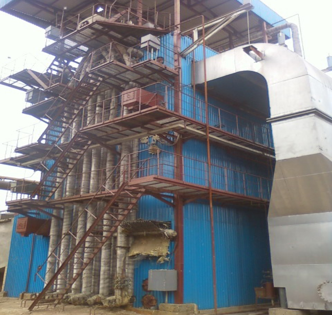
Power plant boiler efficiency is mainly affected by four groups of factors: fuel characteristics, combustion and air management, heat-transfer and flue-gas heat-recovery performance, and boiler operating conditions.
These factors determine how much of the fuel’s energy becomes useful energy in steam and how much leaves the boiler through hot flue gas, moisture, incomplete combustion, deposits, radiation, and other loss pathways.
In this article, boiler efficiency means the fuel-to-steam thermal efficiency of the boiler or fired steam generator. It should not be confused with the overall fuel-to-electricity efficiency of the complete power plant.
ASME PTC 4 treats fired-steam-generator efficiency through an energy-balance framework, which provides a useful way to understand the subject: boiler efficiency changes when the useful steam output or one or more energy-loss pathways change.
Key Factors Affecting Power Plant Boiler Efficiency at a Glance
Key Factor
What Changes
Main Effect on Boiler Efficiency
Fuel characteristics
Moisture, ash, consistency and combustion characteristics
Changes moisture-related losses, burnout behavior and deposit formation
Combustion and air management
Excess air, insufficient air, fuel-air distribution and air leakage
Changes dry-flue-gas loss and incomplete-combustion loss
Heat transfer and flue-gas heat recovery
Fouling, slagging, surface condition, economizer and air-preheater performance
Changes how much released heat reaches the water/steam circuit instead of leaving with exhaust gas
Boiler load and operating conditions
Load level, load variation, control stability and equipment condition
Changes combustion performance, heat transfer and the relative importance of fixed losses
These factors are interconnected. Fuel properties, for example, can influence combustion behavior and deposit formation; fouling can then reduce heat transfer and contribute to a higher flue-gas exit temperature.
The useful engineering question is therefore not simply “Which factor matters most?” but:
How does each factor change the path by which fuel energy is converted into useful steam?
1. How Do Fuel Characteristics Affect Boiler Efficiency?
Fuel is an important boundary condition for boiler performance, but it is misleading to reduce the issue to “high-quality fuel gives high efficiency.”
What matters is how specific fuel properties interact with the combustion system and boiler design.
Fuel Moisture
Moisture contained in solid fuel must be heated and evaporated during combustion.
That process consumes part of the energy released by the fuel, and some of the resulting energy leaves the boiler with water vapor in the flue gas rather than being transferred into the steam-water circuit.
The U.S. Department of Energy’s CIBO Energy Efficiency Handbook identifies moisture in fuel as one component of stack-gas heat loss.
The general relationship is:
Higher fuel moisture → more energy required to heat and evaporate water → greater potential moisture-related stack loss
The actual efficiency impact is not a universal fixed percentage. It depends on fuel composition, boiler configuration, combustion conditions, flue-gas temperature, and the efficiency basis used.
For this reason, claims such as “every 1% increase in fuel moisture reduces boiler efficiency by X%” should only be used when they are supported by data from comparable operating conditions.
Ash and Deposit-Forming Characteristics
Ash is noncombustible material. Its influence on boiler efficiency goes beyond simply adding inert mass to the fuel.
The chemical and physical properties of ash can affect:
slagging in the furnace;
fouling of convective heating surfaces;
heat-transfer characteristics of deposits; and
the amount of combustible material that may remain in bottom ash or fly ash.
U.S. Department of Energy analysis of thermal-coal properties notes that ash accumulation on boiler heat-transfer components can affect efficiency and reliability, and that ash chemistry influences how deposits form and behave on heating surfaces.
The important point is not:
High ash = automatically low boiler efficiency.
The more accurate conclusion is:
Fuel ash characteristics must be compatible with the combustion system, furnace design, heat-transfer surfaces, and cleaning strategy.
This distinction is especially important in boilers designed for coal, biomass, or other fuels with substantial variation in ash behavior.
Fuel Consistency and Burnout Characteristics
Fuel properties can also influence how reliably complete combustion is achieved.
For solid-fuel boilers, relevant characteristics can include:
moisture variation;
particle-size distribution;
volatile matter and fixed-carbon characteristics;
ash content;
fuel preparation; and
consistency of the fuel-feeding system.
Poor preparation or unstable fuel characteristics can make air-fuel control and complete burnout more difficult.
The DOE-hosted CIBO handbook specifically identifies unburned carbon in bottom ash and fly ash as a heat-loss mechanism in solid-fuel combustion and emphasizes proper fuel preparation and combustion-air control.
Does Higher Heating Value Automatically Mean Higher Boiler Efficiency?
No.
A higher heating value means that a unit mass or volume of fuel contains more chemical energy. It does not by itself prove that the boiler converts a higher percentage of that energy into useful steam.
A boiler burning a lower-heating-value fuel may still achieve strong thermal efficiency if the furnace, combustion system, heat-transfer surfaces, and operating strategy are properly matched to that fuel.
This is why fuel selection and boiler design should be considered together rather than judging boiler efficiency from calorific value alone.
2. How Do Combustion Quality and Air Management Affect Boiler Efficiency?
Efficient combustion requires enough air to release the fuel’s chemical energy completely—but not so much air that unnecessary gas must be heated and discharged through the stack.
This creates one of the most important operating balances in boiler efficiency.
Excess Air Increases Dry Flue-Gas Heat Loss
Combustion requires oxygen, but practical boilers use more air than the exact theoretical requirement to ensure complete combustion.
If excess air rises beyond what is necessary for stable operation, the boiler must heat a larger quantity of nitrogen, unused oxygen, and other gas constituents. That additional gas then leaves through the stack carrying sensible heat.
Excess air increases → flue-gas mass increases → more sensible heat can leave through the stack
Flue-gas O₂ is therefore a useful operating indicator, but it must be interpreted in context.
High O₂ measured at the stack does not necessarily mean that all of the additional oxygen entered through the burners. Air can also enter downstream through leakage in ducts, casings, access doors, seals, or other parts of the flue-gas path.
Too Little Air Can Cause Incomplete Combustion
Reducing excess air too far creates the opposite problem.
If oxygen availability or fuel-air mixing becomes insufficient, part of the fuel may not burn completely.
The result can include:
elevated carbon monoxide;
unburned carbon in fly ash;
unburned combustible material in bottom ash;
soot formation; and
unstable combustion.
In those conditions, chemical energy remains in unburned or partially burned material rather than being released as useful heat.
The DOE-hosted CIBO Energy Efficiency Handbook describes both sides of this trade-off: excessive air increases energy loss, while insufficient air can result in incomplete combustion and wasted fuel.
The Goal Is Not Minimum Air—it Is Correct Air
This distinction matters.
A common oversimplification is:
“Lower excess air always means higher efficiency.”
A better engineering statement is:
Boiler efficiency benefits from maintaining the lowest practical excess-air level that still supports stable and sufficiently complete combustion under the actual fuel and load conditions.
The optimum value is not universal. It depends on fuel, firing system, burner or grate design, boiler load, fuel preparation, measurement accuracy, and combustion stability.
3. How Do Heat Transfer and Flue-Gas Heat Recovery Affect Boiler Efficiency?
Combustion can release fuel energy successfully and the boiler can still lose efficiency if that heat is not transferred effectively into the water and steam.
This is why heating-surface condition and flue-gas heat recovery are central to boiler thermal efficiency.
Soot, Slagging and Fouling
Coal, biomass, oil, and some waste-derived fuels can produce deposits on furnace walls and convective heating surfaces.
These deposits introduce additional resistance between the hot combustion gases and the water/steam circuit.
In simplified form:
Deposits increase → thermal resistance increases → heat absorption falls → more heat may remain in the flue gas
The U.S. Department of Energy’s Operations & Maintenance Best Practices Guide notes that fouling can increase stack temperature and reduce boiler efficiency. Babcock & Wilcox likewise notes that appropriate sootblowing improves heat transfer by reducing fouling and plugging.
However, the effect should not be expressed using a generic claim such as:
“1 mm of soot reduces boiler efficiency by 5%.”
Deposit severity depends on where the deposit forms, its thermal properties, thickness, composition, boiler geometry, gas temperature, and operating condition.
Water-Side Deposits Also Matter
Heat-transfer resistance is not limited to the gas side.
Scale or other deposits on water-side heating surfaces can also inhibit heat transfer. DOE guidance notes that such deposits can leave more heat in the combustion gases rather than allowing it to enter the boiler water.
For power boilers, however, detailed water chemistry, deposition mechanisms, and tube-failure prevention are separate subjects. The key point here is simply:
Clean and properly conditioned heat-transfer surfaces are necessary for maintaining the intended transfer of combustion heat into the steam-water circuit.
Economizer Performance
Even after flue gas passes through the main boiler heating surfaces, it can still contain useful thermal energy.
An economizer recovers part of that energy by transferring heat from the flue gas to incoming boiler feedwater.
The DOE’s Use Feedwater Economizers for Waste Heat Recovery guidance describes this directly: recovering flue-gas heat into feedwater reduces the amount of additional fuel energy required for steam generation.
If economizer heat transfer deteriorates, more useful energy can remain in the exhaust gas.
Air-Preheater Performance
An air preheater performs a similar recovery function but transfers flue-gas heat to incoming combustion air.
The more recoverable heat that leaves unused with the flue gas, the more fuel energy is required to produce the same useful steam output.
Why Flue-Gas Exit Temperature Is Important—but Is Not a Root Cause
Flue-gas exit temperature is one of the most useful indicators of boiler heat-transfer performance.
If exit temperature rises under otherwise comparable conditions, more sensible heat may be leaving through the stack.
But high stack temperature is an indicator, not a diagnosis by itself.
Possible causes include:
fouling or slagging;
degraded economizer performance;
degraded air-preheater performance;
excessive flue-gas flow;
changes in fuel;
changes in excess air;
changes in boiler load; or
limitations inherent in the boiler design.
DOE guidance recommends trending stack temperature because a rising value can indicate reduced heat-transfer performance.
The correct question is therefore not:
“Is the stack temperature high?”
but:
“Why is the stack temperature different from the appropriate baseline for this fuel, load, and boiler condition?”
4. How Do Boiler Load and Operating Conditions Affect Efficiency?
Boiler thermal efficiency is not necessarily constant across the entire operating range.
Every boiler is designed around a particular combination of steam output, fuel, combustion conditions, gas flow, and heat-transfer characteristics.
When actual operation moves away from that intended range, the balance of losses can change.
Part-Load Operation
At reduced load, some boilers require proportionally more excess air to maintain stable combustion and good mixing. At the same time, losses that do not fall in direct proportion to output—such as radiation and convection from the boiler enclosure—represent a larger share of the useful output.
The DOE Steam System Survey Guide notes that boiler efficiency varies across the operating range and identifies higher excess-air requirements and relatively fixed shell losses as reasons efficiency may decline at low load.
The exact efficiency-versus-load curve is boiler-specific.
It is therefore not technically correct to claim that:
“Every boiler is most efficient at exactly 100% load.”
Depending on design, firing system, fuel, heat-recovery equipment, and control strategy, the best efficiency may occur within a particular operating range rather than at one universal load point.
Load Changes and Combustion Stability
Frequent or rapid load changes can also make it more difficult to maintain the most favorable combination of:
fuel flow;
combustion-air flow;
excess air;
furnace conditions; and
heat-transfer performance.
This does not mean that flexible operation is inherently inefficient. It means that the combustion and control system must respond appropriately as demand changes.
Control and Instrument Accuracy
Modern boiler control depends on measurements such as:
fuel flow;
combustion-air flow;
flue-gas oxygen;
furnace pressure;
steam flow; and
relevant temperatures.
If instruments drift or control relationships no longer represent actual equipment behavior, the boiler can operate away from its intended fuel-air or load condition.
This is one reason why maintenance should not be treated as an independent thermodynamic efficiency factor.
Maintenance matters because it preserves the physical conditions and measurements that affect efficiency—for example:
clean heating surfaces;
controlled air leakage;
reliable burners or fuel-feeding equipment;
sound insulation and refractory;
accurate instrumentation; and
stable combustion controls.
How Are These Four Efficiency Factors Connected?
The four groups should not be treated as isolated variables.
A change in one can trigger changes in another.
Fuel Characteristics Can Change Combustion
A change in fuel moisture, particle size, or combustion characteristics may alter ignition, burnout, and combustion-air requirements.
The result can appear later as higher O₂, elevated CO, increased unburned carbon, or changes in furnace conditions.
Fuel Characteristics Can Change Heat Transfer
Fuel ash composition can influence slagging and fouling.
The resulting deposits can reduce heat transfer, which may then appear as a change in gas temperatures or steam-side performance.
Combustion Conditions Can Change Stack Loss
Excess air increases flue-gas flow.
If that larger quantity of gas also leaves the boiler at an elevated temperature, more sensible heat can be carried out through the stack.
These examples illustrate why boiler efficiency should be understood as an energy-balance problem rather than a checklist of unrelated factors.
Which Operating Indicators Can Help Reveal an Efficiency Problem?
No single measurement gives a complete diagnosis, but several operating indicators can help show where further investigation is needed.
Operating Indicator
What It May Suggest
Flue-gas O₂
Excess combustion air, air-fuel imbalance, or possible downstream air ingress
CO
Incomplete combustion or inadequate fuel-air mixing
Unburned carbon in ash
Incomplete burnout of solid fuel
Flue-gas exit temperature
Changes in heat recovery, surface cleanliness, gas flow, fuel, or load
Fuel moisture and ash analysis
Changes in fuel-related loss conditions and deposit behavior
Fuel input relative to useful steam output
Change in overall boiler thermal performance
Boiler load trend
Whether efficiency change is associated with off-design operation
These measurements should be evaluated as trends and correlated variables, preferably against a known baseline for comparable fuel and load conditions.
For example:
High stack O₂ alone does not prove that burner excess air is too high.
and:
High stack temperature alone does not prove that the economizer is fouled.
The value of an indicator comes from understanding the mechanism behind it.
What Should Not Be Confused with Boiler Thermal Efficiency?
One of the most common technical mistakes in discussions of power plant boilers is mixing boiler thermal efficiency with overall power plant efficiency.
Higher Steam Pressure and Temperature Do Not Automatically Mean Higher Boiler Thermal Efficiency
Supercritical and ultra-supercritical steam conditions can improve the thermodynamic efficiency of the Rankine power cycle.
That does not mean that a USC boiler automatically has a higher fuel-to-steam thermal efficiency simply because it operates at higher steam pressure or temperature.
Boiler Efficiency Is Not Overall Power Plant Efficiency
The distinction can be summarized simply:
Boiler thermal efficiency: fuel energy → useful steam energy
Overall power plant efficiency: fuel energy → electrical output
A turbine, condenser, generator, pumps, fans, and other plant systems affect overall power-generation efficiency but are outside the boiler’s fuel-to-steam efficiency boundary.
Keeping these metrics separate prevents misleading comparisons.
Conclusion: What Matters Most for Power Plant Boiler Efficiency?
Power plant boiler efficiency is not determined by one fuel property, one temperature, or one technology label.
It depends on how effectively the boiler performs four connected tasks:
Fuel characteristics establish important combustion and heat-transfer conditions.
Combustion and air management determine whether fuel energy is released completely without heating unnecessary excess gas.
Heat-transfer and flue-gas heat recovery determine how much of that released energy reaches the water and steam before the exhaust leaves the system.
Boiler load and operating conditions determine how closely the equipment operates to the conditions for which its combustion, heat-transfer, and control systems were designed.
For engineers evaluating a loss of boiler efficiency, the most useful approach is therefore to connect:
Factor → physical loss mechanism → observable operating indicator → effect on fuel-to-steam performance
What are the main factors affecting power plant boiler efficiency?
The main factors are fuel characteristics, combustion and air management, heat-transfer and flue-gas heat-recovery performance, and boiler operating conditions.
These factors influence different energy-loss pathways, including moisture-related loss, dry-flue-gas loss, incomplete-combustion loss, reduced heat transfer, and off-design operating losses.
How does fuel moisture affect boiler efficiency?
Fuel moisture must be heated and evaporated during combustion. Part of the energy used for this process leaves with water vapor in the flue gas instead of becoming useful steam energy.
The actual efficiency impact depends on fuel composition, boiler design, flue-gas conditions, and operating load, so a universal percentage penalty should not be assumed.
Why does excess air reduce boiler efficiency?
Excess combustion air increases the quantity of gas that must be heated inside the boiler and then discharged through the stack.
This can increase dry-flue-gas sensible heat loss.
However, reducing air too far can cause incomplete combustion, so the objective is not minimum air but the appropriate excess-air level for stable, complete combustion.
How does fouling reduce boiler efficiency?
Soot, ash, slag, or other deposits on heating surfaces add thermal resistance.
This can reduce heat transfer from hot combustion gases into the water and steam, leaving more energy in the flue gas.
A rising stack temperature under comparable operating conditions can be one indication of degraded heat transfer, although it does not identify the cause by itself.
Why is flue-gas exit temperature important for boiler efficiency?
Flue gas leaving at a higher temperature carries more sensible heat out of the boiler.
However, high exit temperature is an indicator rather than a root cause. Fouling, degraded heat recovery, excessive gas flow, changes in excess air, fuel changes, and load conditions can all affect stack temperature.
Does higher steam pressure always improve boiler efficiency?
No.
Higher steam pressure and temperature can improve overall steam-cycle or power plant efficiency, particularly in supercritical and ultra-supercritical plants.
They do not automatically determine the boiler’s fuel-to-steam thermal efficiency, which depends on the boiler’s actual energy inputs, useful steam output, and heat losses.
Analysis of how coal moisture, ash characteristics, unburned carbon, and ash deposition can influence combustion, heat-transfer performance, and generating efficiency.
There is no single most efficient type of power plant boiler under every definition of efficiency.
If “efficiency” refers to the overall efficiency of a large conventional coal-fired steam power plant, ultra-supercritical (USC) steam conditions can support some of the highest commercially demonstrated efficiencies among mature Rankine-cycle coal technologies.
However, if the comparison refers specifically to boiler thermal efficiency, USC cannot simply be declared the winner based on plant-efficiency percentages. Boiler efficiency measures how effectively fuel energy is transferred to water and steam, while overall power plant efficiency measures how much of the fuel energy ultimately becomes electricity.
Key Takeaway: A USC coal-fired power plant can achieve an overall plant efficiency in the 40% range while the boiler itself has a substantially higher fuel-to-steam thermal efficiency. These figures are not contradictory because they measure different stages of the energy-conversion process.
On a lower-heating-value (LHV) basis, the IEA states that:
subcritical coal-fired plants can reach roughly 33–37% efficiency;
supercritical coal-fired plants can reach around 44%; and
ultra-supercritical coal-fired plants can reach up to 47.5%, based on the IEA’s 2023 reference point.
These figures describe overall coal-fired power plant efficiency, not boiler thermal efficiency.
That distinction should be established before any boiler or steam technology is described as “more efficient.”
Boiler Efficiency and Power Plant Efficiency Are Not the Same
One of the most common problems in discussions of power plant boiler efficiency is treating two fundamentally different metrics as if they were interchangeable.
They are not.
What Does Boiler Thermal Efficiency Measure?
Boiler thermal efficiency describes how effectively the energy supplied by the fuel is converted into useful thermal energy in the generated steam.
In simplified terms:
Fuel energy input → useful energy transferred to water and steam
The U.S. Department of Energy’s Steam System Survey Guide relates fuel energy input to steam energy through boiler efficiency.
Energy that does not reach the steam is associated with losses such as:
heat leaving with the flue gas;
moisture-related losses;
incomplete combustion; and
radiation and convection from boiler surfaces.
The purpose here is not to calculate each loss in detail. The important point is that boiler efficiency describes the fuel-to-steam part of the process.
What Does Overall Power Plant Efficiency Measure?
Overall power plant efficiency covers a much longer conversion chain:
The boiler is therefore only one part of the complete plant.
As described in Mitsubishi Power’s overview of conventional steam power plants, the boiler generates high-pressure, high-temperature steam, the steam turbine converts the steam’s thermal energy into mechanical energy, and the generator converts that mechanical energy into electricity.
Overall plant efficiency therefore reflects more than boiler performance. It also depends on the steam cycle, turbine performance, condenser conditions, auxiliary power consumption and other plant-level losses.
Why the Two Numbers Should Never Be Compared Directly
Consider a simplified example:
boiler thermal efficiency: approximately 90%;
net plant efficiency: approximately 40%.
These figures are not contradictory.
The first measures the conversion of fuel energy into steam energy. The second measures the broader conversion of fuel energy into electrical output after the entire steam-power cycle.
This is why saying that “a USC boiler is 47% efficient” is potentially misleading.
A figure around 47% in a USC discussion normally refers to overall plant or cycle efficiency, not the boiler’s fuel-to-steam thermal efficiency.
Why Do Ultra-Supercritical Steam Conditions Improve Power Plant Efficiency?
The efficiency advantage associated with ultra-supercritical technology comes primarily from improving the steam cycle.
Higher steam pressure and temperature enable a Rankine-cycle power plant to convert a greater share of supplied thermal energy into useful mechanical and ultimately electrical output.
Mitsubishi Power notes in its once-through boiler technical overview that raising steam pressure and temperature can improve power-generation efficiency while reducing fuel consumption.
Higher Steam Temperature and Pressure Improve the Steam Cycle
In engineering terms, increasing main-steam and reheat temperatures raises the average temperature at which heat is added to the cycle. Together with suitable pressure levels and reheat arrangements, this improves the thermodynamic performance of the Rankine cycle.
The practical result is straightforward:
More electrical output can be produced from a given amount of fuel.
This should not be explained by saying that USC “eliminates latent heat losses” or that “boiling itself causes an efficiency loss.”
Latent heat is part of the thermodynamic process, not inherently a boiler loss.
The relevant advantage is the improvement in overall cycle efficiency achieved through higher steam conditions.
Subcritical vs. Supercritical vs. Ultra-Supercritical
Steam Condition
General Technical Characteristic
Effect on Plant Efficiency
Typical Application
Subcritical
Operates below the critical pressure of water
Lower steam-cycle efficiency
Conventional steam power plants
Supercritical
Operates above the critical pressure and commonly uses once-through steam generation
Higher steam-cycle efficiency
Large modern coal-fired units
Ultra-supercritical (USC)
Uses higher steam temperatures and pressures than conventional supercritical systems
Among the highest efficiencies achieved by mature coal-fired Rankine-cycle technologies
Large high-efficiency coal-fired power generation
The IEA describes the same progression: subcritical plants are less efficient than supercritical plants, while ultra-supercritical plants can achieve still higher overall plant efficiencies.
USC is also a commercially established technology rather than merely a research concept. Mitsubishi Power lists numerous operating supercritical and ultra-supercritical once-through boiler references in its commercial portfolio.
Does Ultra-Supercritical Mean “The Most Efficient Boiler”?
Not necessarily.
Part of the confusion comes from mixing different ways of classifying power plant boilers.
USC Describes Steam Conditions, Not Combustion Technology
A power plant boiler can be classified along several different dimensions.
By combustion technology:
pulverized coal combustion (PC/PCC);
circulating fluidized bed combustion (CFB).
By water/steam-side configuration:
drum boiler;
once-through steam generator.
By steam conditions:
subcritical;
supercritical;
ultra-supercritical.
These are not all mutually exclusive categories.
For example, the IEA’s definition of pulverized coal combustion includes subcritical, supercritical and ultra-supercritical steam plants. A pulverized-coal-fired plant can therefore operate at different steam-condition levels.
Likewise, Mitsubishi Power distinguishes drum boilers and once-through boilers according to their water/steam-side configuration, while treating steam conditions as another design characteristic.
This is why expressions such as “CFB vs. supercritical boiler” need to be used carefully.
A CFB Boiler Can Also Operate at Supercritical Steam Conditions
CFB describes a combustion technology.
Supercritical describes a steam condition.
They are therefore not technical opposites.
Sumitomo SHI FW states in its CFB boiler technical information that large-scale CFB boilers can support supercritical steam conditions, with published conditions reaching temperatures up to 603°C and pressures up to 257 bar.
Therefore, a technically valid plant description could be:
USC Does Not Guarantee the Highest Boiler Thermal Efficiency
Even when a steam generator operates within a USC power plant, its fuel-to-steam thermal efficiency still depends on the complete boiler design and actual operating conditions.
Important influences include fuel properties, excess air, combustion performance, stack temperature, heat-transfer surface condition, unburned fuel losses and operating load.
The USC label alone is therefore not enough to determine boiler thermal efficiency.
So, What Is the Most Efficient Type of Power Plant Boiler?
The technically correct answer depends on what is being measured.
For Overall Efficiency in Large Coal-Fired Steam Power Plants
For large conventional coal-fired steam power generation, a modern once-through steam generator operating at ultra-supercritical steam conditions can support some of the highest commercially demonstrated overall plant efficiencies among mature Rankine-cycle coal technologies.
The wording matters.
A USC steam generator:
supports high overall plant efficiency
It should not automatically be described as:
having a boiler thermal efficiency of 45–47%.
According to the IEA, the progression from approximately 33–37% for subcritical plants to around 44% for supercritical plants and up to 47.5% for USC plants reflects an improvement in overall coal-fired plant efficiency on an LHV basis.
It does not represent the thermal efficiency of the boiler alone.
For Boiler Thermal Efficiency Alone
There is no universal winner based solely on whether a boiler is classified as subcritical, supercritical or ultra-supercritical.
Actual boiler thermal efficiency must be evaluated according to the project’s:
fuel characteristics;
boiler and heat-recovery design;
operating conditions;
measured heat losses; and
applicable efficiency calculation method or standard.
Two boilers cannot be ranked reliably by simply attaching overall plant-efficiency figures to the boiler itself.
What About Gas-Fired Combined-Cycle Plants?
Another important boundary is gas-turbine combined-cycle power generation.
Modern gas-turbine combined-cycle plants can achieve overall electrical efficiencies higher than conventional coal-fired steam plants. Mitsubishi Power currently publishes combined-cycle efficiency above 64% for its M501J/JAC series.
However, this is a different power-generation architecture.
In a combined-cycle plant, a gas turbine generates electricity first. Its high-temperature exhaust then enters a heat recovery steam generator (HRSG), which produces steam for a steam turbine.
The U.S. Department of Energy explains this process in How Gas Turbine Power Plants Work, describing the HRSG as equipment that captures heat from the turbine exhaust to generate steam.
Therefore:
64%+ combined-cycle plant efficiency should not be compared directly with the thermal efficiency of a fired boiler.
They measure different systems.
Is the Highest-Efficiency Boiler Always the Best Choice?
No.
The technology associated with the highest possible plant efficiency is not automatically the best solution for every power project.
A practical boiler configuration must also match the available fuel, generating capacity, required steam conditions, load profile, emissions requirements, capital budget, operating strategy and local maintenance capability.
Fuel flexibility can be particularly important. A plant expected to burn difficult fuels, variable-quality fuels or biomass-derived materials may prioritize combustion flexibility differently from a large baseload utility plant designed around a consistent pulverized-coal supply.
Likewise, a project requiring frequent load changes may have different priorities from a continuously operating baseload unit.
Efficiency should therefore be treated as one part of a broader technical and economic assessment rather than as the only selection criterion.
Conclusion: The Most Efficient Power Plant Boiler Depends on What You Measure
So, what is the most efficient type of power plant boiler?
If the question refers to the overall efficiency of large conventional coal-fired steam power generation, ultra-supercritical steam conditions combined with modern once-through steam generation can support some of the highest commercially demonstrated efficiencies among mature coal-fired Rankine-cycle technologies.
But that does not mean a USC boiler itself has a thermal efficiency of 40–50%.
Once those two metrics are separated, the comparison becomes much clearer.
For an actual power plant project, efficiency should be evaluated together with fuel properties, required steam conditions, capacity, emissions targets, operating profile and lifecycle economics rather than treated as a standalone specification.
FAQ
Is an ultra-supercritical boiler more efficient than a supercritical boiler?
When comparing overall coal-fired power plant efficiency, ultra-supercritical steam conditions generally support higher efficiency than conventional supercritical conditions because higher steam temperatures and pressures improve steam-cycle performance.
The IEA reports around 44% LHV efficiency for supercritical coal plants and up to 47.5% for ultra-supercritical plants.
However, these are plant-efficiency figures. They do not mean that every USC boiler automatically has a higher fuel-to-steam thermal efficiency than every supercritical boiler.
What is the difference between boiler efficiency and power plant efficiency?
Boiler efficiency measures fuel-to-steam energy conversion.
Power plant efficiency measures fuel-to-electricity energy conversion.
Overall plant efficiency therefore includes performance and losses associated with the boiler, steam cycle, turbine, generator, condenser and auxiliary systems.
Why do higher steam temperatures improve power plant efficiency?
Higher steam temperatures, together with appropriate pressure and reheat conditions, increase the average temperature at which heat is added to the Rankine cycle.
This improves thermodynamic cycle efficiency and allows more of the fuel’s energy to be converted into electrical output.
Can a CFB boiler be supercritical?
Yes.
CFB describes combustion technology, while supercritical describes steam conditions.
Sumitomo SHI FW states that large-scale CFB boilers can support supercritical steam conditions up to 603°C and 257 bar. Therefore, “CFB” and “supercritical” should not always be treated as competing boiler categories.
Are combined-cycle gas power plants more efficient than USC coal plants?
Modern gas-turbine combined-cycle plants can achieve higher overall power-generation efficiencies than conventional USC coal-fired steam plants. Mitsubishi Power, for example, publishes combined-cycle efficiency above 64% for its J/JAC-class systems.
However, this is not a boiler-to-boiler comparison. A combined-cycle plant combines a gas turbine, HRSG and steam turbine, so the published efficiency represents the entire generating system rather than the thermal efficiency of a fired boiler.
Definitions and efficiency comparisons for subcritical, supercritical and ultra-supercritical coal-fired power plants, including LHV-based plant-efficiency figures.
Technical information on once-through boiler technology and the role of higher steam pressure and temperature in improving power-generation efficiency.
Technical information confirming that large-scale CFB boilers can operate at supercritical steam conditions, with published conditions up to 603°C and 257 bar.
Procuring a waste heat recovery boiler from the wrong supplier doesn’t just mean a slower-than-expected payback — it means months of underperformance, repeated tube failures at the superheater pendant sections, and a commissioning team camped on your site arguing over who owns the fouling problem. Plants in cement, steel, and glass industries routinely vent 300–650°C flue gas into atmosphere because a boiler proposal looked competitive on paper but fell apart on thermal design detail or after-sales response time. That lost heat is lost money, and in most cases it compounds silently for years before anyone runs the numbers.
The right questions to ask a waste heat recovery boiler supplier cover six core areas: flue gas characterization and thermal design methodology, material and pressure part specifications, guaranteed thermal efficiency (typically 85–95% depending on inlet temperature and surface design), capacity range and steam parameters, compliance documentation, and after-sales support structure. Asking these questions before contract protects payback periods that realistically run 18–36 months in well-matched installations.
What separates a supplier who can genuinely engineer your application from one who is resizing a catalog unit and hoping it fits is usually visible within the first two or three technical exchanges — if you know what to ask. The questions that follow are the ones that tend to reveal it.
How Well Does the Supplier Understand Your Specific Waste Heat Source and Process Conditions?
This is, honestly, the single most revealing line of questioning you can run. A supplier who immediately asks for your flue gas composition report, temperature trend logs, and process upset history is showing you something real. One who asks only for “approximate flow rate and temperature” before producing a preliminary sizing sheet — that’s a red flag worth taking seriously.
Match Supplier Experience to Your Exact Heat Source Type
Cement kiln exhaust, electric arc furnace converter gas, sintering machine flue gas, float glass furnace off-gas, and diesel or gas engine exhaust are not interchangeable applications. The dust chemistry alone separates them completely. Kiln exhaust carries sticky alkali-rich dust that can sinter onto heat surfaces at temperatures above roughly 650–700°C; engine exhaust is comparatively clean but arrives at sharply variable temperatures depending on load. Glass furnace off-gas typically brings SO₂ concentrations and alkali vapors that drive corrosion on low-temperature heat surfaces — so the acid dewpoint calculation isn’t academic, it determines where you put your economizer and what you make it from.
Ask the supplier directly: how many installations do you have running on this specific source type? What tube material and spacing did you use, and what was the actual fouling rate after 12 months of operation? If they can’t give you operating plant data — even anonymized — from a comparable application, that’s worth weighing carefully.
Flue Gas Characterization Is Not Optional
A competent supplier needs the full data package before they design anything meaningful: flue gas volumetric flow (Nm³/h), inlet temperature at normal and peak conditions, dust loading in g/Nm³, particle size distribution if available, and concentrations of corrosive species — SO₂, HCl, alkali vapors, and moisture content. Each of these drives a configuration decision.
Accurate flue gas dust loading data is essential for correct sootblower spacing and heat surface arrangement in a waste heat recovery boilerTrue
Dust loading (g/Nm³) directly determines whether the boiler needs wide tube pitch, rapping systems, or steam sootblowers, and under-specifying this leads to bridging and rapid fouling that degrades heat transfer within weeks of startup.
High dust loading — above roughly 30–50 g/Nm³, common in cement and sintering applications — typically forces wider tube pitch, vertical gas flow arrangement, and either rapping gear or retractable sootblowers. Skipping this analysis and defaulting to a compact design will produce a boiler that’s fouled within two to three months.
Design for a Range, Not a Single Point
Process conditions vary. Kilns go through start-up cycles. Furnaces are tapped intermittently. Engines ramp up and down with load. A boiler sized only for the “normal operating point” can see damaging thermal cycling if the supplier hasn’t designed the pressure parts and drum internals for the real operating envelope — which typically means accounting for inlet temperatures anywhere from 30% below normal up to peak excursions that can exceed the design point by 80–100°C in some metallurgical applications.
Ask specifically: what is the design inlet temperature, and what is the maximum allowable inlet temperature the boiler can tolerate without requiring a bypass? How does the steam drum pressure respond during a rapid load drop? A supplier who has thought this through will have a clear answer. One who hasn’t will give you a vague reference to “standard safety margins.”
Fouling Management and Cleaning Systems
Sootblowers, rappers, and pulse-jet systems are not interchangeable. Rotary or retractable steam sootblowers suit moderate sticky dust; mechanical rapping works better for dry, loosely adhering ash; pulse-jet systems are sometimes used at lower temperature zones. The wrong choice means cleaning cycles that either damage tube surfaces or simply don’t remove the deposit layer.
Watch for suppliers who propose a single cleaning system across all temperature zones without justification. In practice, a well-designed WHRB for a cement or steel application often uses different cleaning strategies in different passes — because the dust behavior changes as the gas cools through the unit.
Flow Rate Fluctuation and Pressure Part Protection
Rapid gas flow reduction — during a process upset, emergency shutdown, or planned maintenance — creates thermal shock risk if the supplier hasn’t accounted for it. Ask how the boiler handles a sudden 50–70% reduction in gas flow. The answer should cover bypass damper response time, drum level control strategy during the transient, and any minimum flow requirements to keep circulation adequate in natural-circulation designs.
Suppliers who apply a generic shell-and-tube configuration to all WHRB applications regardless of source type are, in my experience, almost always optimizing for fabrication simplicity rather than your operating conditions. That choice tends to show up later — as tube failures, fouling outages, or thermal fatigue cracking in the drum — rather than in the initial quote.
What Thermal Design Methodology and Performance Guarantees Can the Supplier Provide?
This is where you separate the engineering offices from the sales offices. Any supplier can quote a steam output figure. What you need to know is how they arrived at it — and whether they’ll stand behind it contractually when the unit is running in your plant at 3 a.m. in August.
Heat Transfer Calculation Standards and Documentation
Start by asking which standards govern their thermal design. Reputable manufacturers will reference ASME, EN 12952, GB/T 16507, or recognized in-house methodologies derived from those frameworks. Proprietary software isn’t automatically a red flag — some suppliers have genuinely refined tools built on decades of installed units — but you should ask whether their software outputs a traceable calculation report you can review, or whether the thermal sizing lives in a black box you’re expected to trust.
Request the full heat transfer calculation package before you sign anything. A credible supplier hands this over without drama. It should show surface area allocation across the superheater, evaporator, and economizer, the log mean temperature difference at each section, overall heat transfer coefficients assumed, and the fouling factors applied to the flue gas side. If those fouling factors look suspiciously optimistic for your dust-laden kiln exhaust, push back.
What Exactly Is Guaranteed — and at What Conditions?
This matters more than most buyers realize. A WHRB rated at, say, 35 t/h of steam is meaningless unless the guarantee specifies the corresponding flue gas inlet temperature, flue gas mass flow, inlet composition (including dust loading), steam pressure, steam temperature, and the exhaust gas outlet temperature the unit achieves. Strip any one of those boundary conditions out and the number becomes decorative.
Guaranteed parameters you should lock into the contract: steam flow rate in t/h, steam pressure in MPa (whether saturated or superheated), steam temperature in °C, boiler thermal efficiency at design point (realistically 85–92% for most industrial applications, up to around 95% under favorable conditions with low-temperature economizer sections), and the stack outlet temperature — because that last number directly tells you how much energy you’re throwing away.
Design-Point vs. Part-Load Performance
Plants rarely run at nameplate conditions. A cement kiln during a production ramp-up, a glass furnace cycling between pull rates, a steel reheat furnace on a weekend shift — the flue gas flow and temperature swing considerably. Ask for the part-load performance curve, not just the design-point spec sheet. You want to know what the boiler does at 70% and 50% of rated gas flow: does steam output fall gracefully, or does the drum pressure destabilize?
Suppliers who can’t produce a part-load curve are usually telling you something about how much of their design is genuinely calculated versus copied from a previous job.
Pinch Point and Approach Temperature — Ask the Question Directly
In a WHRB evaporator and economizer circuit, the pinch point temperature difference (typically 8–20°C, depending on heat surface cost trade-offs) and the approach temperature set how efficiently the unit extracts heat without risking steaming in the economizer. A supplier who can’t immediately define the pinch and approach temperatures they’ve selected, and explain why, hasn’t really designed a boiler for your conditions. They’ve sized a generic unit and hoped it fits.
Tight pinch points recover more heat but cost more in surface area and can cause operational instability if the gas flow varies. That’s a real trade-off worth discussing explicitly.
Thermal Model Validation and Site Acceptance Testing
Ask whether their thermal model is validated against CFD simulation, physical test data from similar installed units, or purely empirical correlations. None of those approaches is inherently wrong, but each carries different uncertainty margins. An experienced supplier will typically combine correlations from past units with some CFD work on the convective pass geometry.
More important: get the performance acceptance test protocol in writing before contract award. This should reference a recognized standard — ASME PTC 4.1 or an agreed equivalent — specify the measurement instruments, the stabilization period required, and the acceptable tolerances. Then define the penalty structure for underperformance clearly. Vague language like “the supplier will rectify deficiencies” is not a clause; it’s a delay strategy.
A supplier who refuses to share thermal calculation documentation or declines a contractual performance acceptance test is a significant project risk, regardless of price.True
Thermal transparency and acceptance testing are standard practice among established industrial boiler manufacturers. Refusal typically signals either that the design lacks rigor or that the supplier intends to dispute underperformance claims after commissioning — both outcomes that cost the buyer far more than any upfront price difference.
Which Material Specifications and Pressure Part Standards Does the Supplier Apply?
This is where a lot of buyers lose money. A supplier can produce a beautiful thermal calculation, quote a competitive price, and still deliver a boiler built to the wrong code for your jurisdiction — or one that uses carbon steel tube grades in zones that will see 520°C flue gas. The resulting failures aren’t dramatic; they’re slow. Tube thinning over 18 months, a hairline crack at a header weld, economizer corrosion that looks like scale until it becomes a leak. Getting material and code questions right upfront costs nothing. Getting them wrong costs a mid-life refit.
Confirm Which Design Code Actually Governs the Pressure Parts
The first thing to establish is which boiler and pressure vessel code the supplier is certified to build under — not which codes they’re familiar with, but which certificates they hold on the shop floor today. ASME Section I is the baseline requirement for most North American and many export projects; EN 12952 governs water-tube boilers sold into European markets; GB/T 16507 is the Chinese national standard. Each has different minimum wall thickness calculations, allowable stress tables, and inspection hold-point requirements.
Some projects need more than one code because the destination country mandates local certification on top of a recognized international standard. Ask specifically. A supplier who can only offer GB/T 16507 but is quoting for a plant in Southeast Asia or the Middle East needs to demonstrate either a code equivalency agreement or the capacity to have a third-party authorized inspection agency (AIA) witness the build to ASME or EN requirements.
A supplier holding an ASME 'S' stamp can manufacture boilers to ASME Section I regardless of where they are geographically located, provided an authorized inspection agency witnesses fabrication and signs off.True
The ASME stamp program is tied to the manufacturing facility and requires third-party AIA involvement during production, not just at final inspection. Location is not the limiting factor; certification and AIA access are.
Tube Material Selection Is Not a Catalog Choice
Carbon steel grades like SA-106 Gr.B or the Chinese equivalent 20G are perfectly adequate for economizer and low-temperature evaporator sections where metal temperatures stay under roughly 400–420°C. Push into the superheater or into zones where flue gas inlet temperatures exceed 550°C, and you need low-alloy steels — T11 or T22 for intermediate duty, T91 for high-temperature superheaters operating above 565°C metal temperature. Ask the supplier to show you where each material transition falls on their tube arrangement drawing, and cross-check it against their thermal profile output.
Austenitic stainless (TP304H, TP347H) comes into the conversation mainly in sulfuric acid plants, certain chemical process WHRBs, or anywhere the gas composition includes aggressive halides. It’s heavier, harder to weld, and expensive — so a supplier defaulting to stainless to avoid the design work on alloy steel isn’t doing you any favors either.
The SO₃ Dew-Point Problem in Economizers
Sulfur in the process gas converts partially to SO₃, which condenses as sulfuric acid on tube surfaces below roughly 130–160°C, depending on SO₃ concentration and local partial pressure of water vapor. The exact dew point varies — don’t let anyone give you a single number without knowing your gas composition. What you want to know is what minimum metal temperature margin the supplier designs to, and how they control it: higher feedwater inlet temperature, minimum load restrictions, or a bypass arrangement.
Ignoring this costs tubes. In practice, economizers in sulfur-bearing applications often see accelerated external corrosion within two to three years if the supplier didn’t account for acid dew-point margins in the original design.
Weld Quality, NDE, and Hydrostatic Testing
Tube-to-header weld joints are the single most common pressure-part failure point in WHRBs that see thermal cycling. Ask what weld procedure specifications (WPS) and procedure qualification records (PQR) the supplier holds, and whether they’re qualified to the applicable code. Random radiography on 10% of welds is the minimum in most standards; for cycling applications or aggressive gas environments, 100% radiography or phased-array UT on header joints is a reasonable ask.
Hydrostatic test pressure should be at least 1.5 times design pressure for ASME Section I construction — confirm this is done with the boiler fully assembled, not section by section, unless the design physically requires staged testing. Get the test certificate as a deliverable, not an afterthought.
Refractory and Casing in High-Dust or High-Radiant Applications
Cement kilns, electric arc furnace off-gas systems, and similar applications send gas into the boiler inlet carrying abrasive particles or with radiant heat loads the bare tube bank wasn’t designed for. Refractory-lined inlet sections, impingement baffles, and abrasion-resistant casing liners are not optional in these cases. Ask the supplier what the expected erosion rate is for their tube spacing and layout given your gas velocity and particle loading — if they can’t answer that, they haven’t done this before for your application type.
Material Traceability and Third-Party Inspection
For international projects, your insurer, your local authority, or your own engineering standards will likely require full material traceability: mill test certificates (MTCs) for every pressure-part heat of material, with chemistry and mechanical properties traceable to the installed tube. Ask for this to be a contractual deliverable from the start, not something assembled after the fact. Some suppliers sub-source tubes from spot markets when their regular mill is backlogged; that’s when traceability gets murky.
Third-party inspection by a recognized firm — Bureau Veritas, TÜV, Lloyd’s Register, or similar — adds cost, typically 1–3% of equipment value depending on scope, but it’s the only independent check between the supplier’s QC department and your plant. On any project above roughly 10 t/h capacity or above 2.5 MPa design pressure, that cost is justified.
What Manufacturing Capabilities, Quality Certifications, and Inspection Processes Does the Supplier Have?
A thermal design that looks flawless on paper can still produce a failed pressure part if the fabrication shop doesn’t have the equipment, certifications, or discipline to execute it. This is the part of supplier evaluation that buyers most often skip — or handle too lightly — and it’s where projects quietly get into trouble.
Pressure Vessel Manufacturing License Scope
Start by asking for the actual license document, not a summary of it. In China, the relevant authority is SAMR (State Administration for Market Regulation) under the TSG 07-2019 framework; other jurisdictions have equivalent statutory bodies. What matters is the rated pressure ceiling the license covers, the maximum drum diameter permitted under that license class, and whether the license is currently valid. A supplier fabricating a 9.8 MPa superheated steam drum under a license that only covers up to 3.8 MPa is a compliance problem — and a liability problem for your project. Ask specifically. Don’t assume.
A valid Chinese pressure vessel manufacturing license issued by SAMR specifies the category, grade, and allowable parameter ranges — including pressure and vessel dimensions — that the manufacturer is legally permitted to fabricate.True
China's TSG 07-2019 Special Equipment Safety Technical Specification mandates that pressure vessel manufacturers hold a government-issued license with explicitly defined scope parameters, renewed periodically through inspection.
In-House Fabrication Infrastructure
The supplier’s equipment list tells you a lot about their real capability ceiling. For WHRB work, the key assets are automatic submerged-arc welding for drums and large-diameter headers (manual welding on pressure drums above roughly 500 mm diameter is a red flag in a quality-conscious shop), CNC tube bending for tight-radius economizer and superheater coils, and shot-blasting facilities for surface prep before coating or insulation. Hydrostatic testing bays need to be sized for your boiler’s drum length and test pressure — typically 1.25–1.5× design pressure — so ask for the bay’s rated capacity in bar and the maximum vessel length they can accommodate.
Load-out logistics matter more than most buyers realize. A boiler module destined for a cement plant in Egypt or a steel mill in Southeast Asia may ship as a partially assembled block weighing 80–150 tonnes. Does the supplier have a heavy-lift gantry crane? What’s the maximum single-lift capacity in the fabrication bay? What road or rail access connects the shop to the nearest port? These aren’t hypothetical concerns — oversized module transport has added months and significant cost to projects where nobody asked these questions early enough.
Third-Party Inspection and Client-Nominated Inspectors
Ask which inspection bodies the supplier has an established working relationship with — TÜV Rheinland, Bureau Veritas, Lloyd’s Register, and SGS are all commonly accepted by international EPC contractors and end-user insurance underwriters. The more useful question, though, is whether the supplier can accommodate a client-nominated inspector at hold points: after final weld completion, before hydrotest, and during final dimensional and surface inspection. Some suppliers resist this. In my experience, the ones who resist it hardest are usually the ones with the most to hide in their weld repair logs.
ISO 9001 and In-Process Quality Controls
An ISO 9001 certificate is table stakes, but what you actually want to understand is how the QMS is applied on the floor. Ask for the weld procedure qualification records (WPQRs) and welder qualification certificates relevant to the pressure and material grade of your boiler. Ask how incoming material traceability is maintained — specifically, how steel plate and tube mill test certificates are linked to the as-built record for each pressure part. Ask what the in-process dimensional check protocol looks like for tube-to-header joints. Generic answers here are a sign the system exists on paper only.
Subcontracting: Not Automatically a Problem, but Always a Question
Some reputable boiler manufacturers subcontract pressure part fabrication — heads, nozzles, occasionally drums — to specialist shops, especially for unusual geometries or high-alloy materials like T91 or 310S. This isn’t automatically a disqualifier. But you need to know which components are subcontracted, who the subcontractor is, what qualification that subcontractor holds, and how the prime supplier conducts surveillance at that facility. A supplier who subcontracts drums without any documented incoming inspection protocol for the finished parts is a different risk profile from one who has a structured supplier audit program and maintains the full material traceability chain.
Reference Projects and Documented Fabrication Evidence
Ask for photographs — real factory photos, not renders — showing comparable projects at key fabrication stages: drum rolling and welding, finned tube assembly, completed pressure part hydrotest, and packaged modules ready for shipment. Ask for at minimum one or two case studies that include post-commissioning operating data: actual steam output, flue gas outlet temperature, and availability figures from the first 6–12 months of operation. Vague references to “hundreds of projects” without supporting documentation are not evidence. A supplier with genuine WHRB experience in cement, glass, or steel applications will have this material and won’t hesitate to share it.
How Does the Supplier Integrate Auxiliary Systems — Drums, Deaerators, Blowdown, Steam Separators, and Flue Gas Ducts?
A bare boiler shell delivered to site with no clarity on where the supplier’s scope ends is one of the most common sources of project overruns in WHRB installations. You end up with interface gaps — nobody owns the expansion joint between the boiler outlet and the downstream duct, or the deaerator turns out to be a separate procurement item that arrives three months late with incompatible flange ratings. Ask this question early and ask it bluntly: what exactly is in your scope, and where does your battery limit stop?
Defining Battery Limits Before Anything Else
Get the supplier to mark up a system boundary drawing — not a marketing schematic, an actual P&ID showing inlet flue gas connection, steam outlet, feedwater inlet, blowdown outlets, chemical dosing connections, and instrument signal handoff points. Any reputable supplier with real project experience will have this document or can produce it quickly. If they hesitate or send you a block diagram with vague arrows, that tells you something.
The battery limit question matters most in EPC-type contracts where multiple vendors intersect. In my experience, the single most contested interface on a typical cement or steel plant WHRB project is the flue gas duct connection — specifically, who performs the thermal expansion analysis for the duct section between the process equipment outlet and the boiler inlet flange. Duct runs in high-temperature applications (inlet gases at 400–900°C are common in these industries) expand significantly, and if the expansion joint design is split between two vendors with no shared analysis, you will get leaks at commissioning, or worse, structural loading transferred into the boiler casing.
Steam Drum Internals and Blowdown Provisions
The steam drum is not a simple pressure vessel. Ask the supplier what separation internals they use — cyclone separators, chevron dryers, or a combination — and what steam purity they guarantee at the drum outlet. For process steam applications, carryover of moisture or dissolved solids damages downstream equipment fast. A supplier who can only say “we meet standard design” without citing a guaranteed steam quality figure (typically expressed as total dissolved solids in the steam, µg/kg) probably hasn’t done many installations where steam quality actually mattered to the end user.
Continuous blowdown connections and chemical dosing nozzles should be standard features, not afterthoughts. If the drum design has no provision for a conductivity-based continuous blowdown control system, you’ll be running manual intermittent blowdown, wasting heat and chemical treatment money every shift.
Deaerator and Feedwater Package Matching
A surprisingly large number of WHRB suppliers offer only the boiler proper and leave feedwater system sizing to the buyer. That creates risk. The deaerator needs to be sized and thermally matched to the boiler’s specific feedwater flow rate and the available heating steam conditions — getting this wrong means either dissolved oxygen carryover into the boiler (leading to pitting corrosion on waterwall tubes within a year or two) or a deaerator that’s chronically oversized and unstable at partial load. Ask the supplier whether they can supply the deaerator, feedwater pumps, and interconnecting pipework as a matched package. Even if you don’t ultimately buy it from them, their answer tells you how much system-level engineering thinking they actually apply.
Bypass Dampers and Diverter Valves
For any application where the waste heat source — a kiln, an EAF, a glass furnace — must stay running even when the WHRB is taken offline for maintenance or trips, the bypass damper or diverter valve is critical process infrastructure. Ask the supplier directly whether this is part of their scope. Ask how fast it can divert: some processes need full divert within 30–60 seconds. Ask about the thermal and mechanical design of the valve seat for high-dust, high-temperature flue gas — a poorly specified damper blade will warp or seize within one operating season in cement plant conditions.
Instrumentation, Controls, and DCS Integration
A WHRB supplier offering a fully integrated PLC-based control panel with interlock logic and DCS integration capability reduces commissioning time compared to a bare boiler with field-wired instruments only.True
Integrated control panels with pre-tested interlock logic and defined DCS signal lists allow parallel commissioning and reduce site wiring and loop-check time significantly; this is consistently reported in multi-vendor WHRB project post-mortems.
Ask whether the supplier includes a PLC-based control panel as part of the package, or whether instrumentation is simply mounted and field-wired to terminals for the buyer’s integrator to deal with. There’s a real cost difference — but also a risk difference. A supplier who has engineered the interlock logic (drum level trips, steam temperature high alarms, low feedwater flow shutdown) understands failure modes in their own design. An integrator hired separately to write that logic from scratch will need months of document review to get there.
Check whether the supplier provides a defined DCS interface — a signal list with tag names, I/O types, and alarm setpoints. Remote I/O cabinets located near the boiler that hardwire back to the plant DCS, rather than long individual cable runs, are standard practice on any well-engineered project. A local HMI at the boiler front for maintenance and startup is not a luxury; operators need it during commissioning before full DCS integration is live.
The suppliers who have genuinely delivered integrated WHRB systems will have a standard scope definition document and a reference list of what auxiliary packages they have previously supplied. Ask for both.
What Is the Supplier’s EPC and Overseas Project Delivery Track Record?
Shipping a boiler is not the same as delivering a working system. That distinction sounds obvious, but it catches international buyers off guard more often than it should. A supplier who can manufacture a competent WHRB pressure vessel may have no real capability to manage foundations, interconnecting pipework, control wiring, local authority approvals, and startup — leaving you to stitch together the gaps with local contractors who have never seen the equipment before. For cement, glass, or steel plants in markets like Southeast Asia, the Middle East, or East Africa, that gap between “equipment supplier” and “EPC contractor” can translate directly into 3–9 months of commissioning delay and cost overruns that dwarf any savings from a lower initial price.
Ask for a Verifiable Project Reference List
Request a list of completed overseas WHRB projects from the past five years. Not a brochure, not a capacity range chart — a specific list: country, industry application, steam output and pressure, year of commissioning, and a name and contact at the client. If the supplier hesitates, that tells you something. A genuine EPC contractor with overseas delivery experience will have client references they are willing to provide, even if some require a confidentiality caveat. Roughly 3–5 verifiable references in geographies comparable to yours is a reasonable minimum to expect from a mid-to-large supplier.
When you get those references, actually call them. Ask specifically about schedule adherence, how the supplier handled unexpected site conditions, and whether the commissioning team was technically competent or seemed to be learning on the job.
Engineering Team Depth Matters More Than Headcount
Ask the supplier to describe their engineering department structure. A capable WHRB EPC team needs process engineers who can translate your flue gas data into a heat balance, mechanical engineers who can design pressure parts and piping to the destination-country code, civil and structural engineers for foundations and steel structures, and electrical and instrumentation engineers who can produce loop diagrams, hazardous area classifications, and a DCS/PLC integration package. If the supplier’s “engineering team” is three thermal designers and everyone else is subcontracted, you should know that before the contract is signed — not after the first engineering submission comes back incomplete.
Local Code Compliance Is Not Optional
This is where purely domestic suppliers often fall short. Destination-country requirements vary significantly: ASME Section I or VIII in North America, PED in the EU, locally adapted pressure vessel codes in countries like India (IBR), Vietnam, or Indonesia — each with its own documentation, third-party inspection, and stamping requirements. Seismic zone classification affects structural steel design in ways that are not trivial. Electrical area classification for gas-related installations can require ATEX or IECEx certified instruments. Ask the supplier directly: have they obtained pressure vessel registration or approval from a national authority outside China before? Who manages that process — the supplier’s own team or the buyer? The answer matters enormously.
A WHRB supplier with documented ASME, PED, or equivalent third-country pressure vessel approvals demonstrates a substantially higher level of engineering and documentation discipline than one operating solely under domestic standards.True
Obtaining foreign code compliance requires full traceability of materials, welding procedures, and inspection records to a recognized third-party body, which is structurally different from self-certified domestic production.
Schedule and Cost Control Tools
Ask what project management methodology the supplier follows and what tools they use to track schedule, cost, and quality. A credible EPC contractor should be able to show you a sample Gantt chart or WBS structure, explain how change orders are managed, and tell you who the single point of contact is for the duration of the project. Vague answers here usually mean informal processes that break down under pressure.
Logistics for Oversized Modules
Large WHRB pressure parts — drums, evaporator sections, economizer modules — frequently exceed standard shipping container dimensions. Ask whether the supplier has handled heavy-lift cargo, port-to-site transport, and installation supervision in locations with limited crane access or difficult road infrastructure. The logistics planning for a 45-tonne steam drum arriving at a port 300 km from a remote cement plant is its own engineering problem. Suppliers with genuine overseas delivery experience will have in-house or retained logistics partners and will talk about this fluently. Those without it will redirect the conversation toward the boiler itself.
Commissioning Support and Handover Documentation
Get specific: will senior process or commissioning engineers travel to site, or will the supplier send relatively junior technicians? For a WHRB in the 10–50 t/h range, commissioning typically runs 3–6 weeks from cold startup to stable operation, depending on process stability and the complexity of the control system. Ask what documentation is handed over at completion — at minimum you should expect as-built drawings, O&M manuals, a commissioning report with baseline performance data, and a spare parts list cross-referenced to manufacturer part numbers. Plants that skip demanding this at contract stage often find themselves chasing incomplete documentation years later during a maintenance outage.
In practice, the EPC track record question separates a manufacturing vendor from a genuine project partner. For an international greenfield installation or a major retrofit, the distinction can define whether the project is a success or a prolonged headache.
What Lifecycle Support, Spare Parts Availability, and Maintenance Agreements Does the Supplier Offer?
Capital cost gets most of the attention during procurement. It shouldn’t. A waste heat recovery boiler running in a cement kiln line or a steel electric arc furnace operates under corrosive, dust-laden, thermally cyclic conditions — and over a 15–20 year asset life, the cumulative cost of spare parts, unplanned downtime, and inadequate technical support will dwarf the original purchase price difference between a well-supported supplier and a cheap one.
Ask this section of questions late in the commercial discussion, when you have enough trust to get real answers rather than polished brochure language.
Spare Parts Lists, Lead Times, and Critical Inventory
Any serious supplier should be able to hand you a recommended initial spare parts list without you asking twice. This list needs to go beyond a vague “consumables package.” You want tube quantities by circuit (economizer, evaporator, superheater separately), tube plugs sized to your tube OD and wall thickness, drum manhole gaskets, handhole gaskets, safety valve trim sets, sootblower elements and drive components if your unit has rotary or retractable types, and drum internals — steam separators, scrubbers, feed distribution pipes.
Lead times matter as much as availability. For forged pressure parts and safety valve trim from a reputable manufacturer — a Dresser-Consolidated or an Aquatrol-equivalent seat-and-disc assembly — you might be looking at 8–16 weeks from order. For custom-formed alloy tubes in a high-temperature superheater circuit (say, T91 or TP347H), lead times can stretch to 20–30 weeks or longer depending on mill schedules and whether tube ends need special welding preparations. If your plant is in Southeast Asia, West Africa, or South America and the boiler is manufactured in China or Europe, you need buffer stock on-site. The supplier should tell you honestly which items are long-lead and help you size a first-fill inventory accordingly.
Proprietary Components and Long-Term Supply Commitments
This is where you need to read the fine print carefully. Some suppliers — not all — design control interfaces, sootblower control panels, or drum level measurement assemblies around proprietary protocols or custom-machined parts that are only available through them. That creates leverage on your maintenance budget for the life of the plant.
Ask directly: which components, if any, require sourcing exclusively from you or your sub-suppliers? Get the answer in writing. If the answer is “none,” ask them to confirm that in the contract. If the answer is “yes, items X and Y,” then negotiate a 10-year pricing cap or a licensed drawing arrangement that lets you machine replacements locally. This conversation is uncomfortable, but skipping it costs money later.
Operator Training and Documentation
A WHRB commissioned without proper operator training is a liability. Flue gas inlet conditions in industrial processes fluctuate — a rotary kiln has different waste heat profiles at startup versus steady-state production — and operators who don’t understand furnace draft control, blowdown sequencing, or the response of drum level to sudden load swings will eventually cause a trip or, worse, a waterside damage event.
The contract should specify classroom training hours, on-site commissioning training, and the language of all operating manuals, P&IDs, and maintenance procedures. For an overseas buyer, having documentation only in Mandarin Chinese or only in German is a genuine operational risk. Confirm early.
Remote Monitoring, Diagnostics, and Support Response Time
Modern WHRB control systems — whether a dedicated PLC panel or integration into a plant-wide DCS — can transmit key operating parameters: drum pressure, flue gas inlet and outlet temperatures, feedwater flow, steam output, and key alarm states. Ask whether the supplier’s standard offering includes remote access capability, and if so, what the committed response time is for a technical support inquiry. “24–48 hours” is a reasonable benchmark; “we’ll get back to you” is not.
Remote diagnostics are especially valuable in the first 12–18 months of operation, when unexpected fouling rates, tube metal temperature deviations, or sootblower cycling issues tend to surface.
Inspection Intervals and Warranty Coverage
Planned inspection requirements for a WHRB typically follow national pressure vessel codes — annual external inspections, biennial internal inspections, and a full pressure test at roughly 10-year intervals, though exact intervals depend on operating jurisdiction and insurance requirements. Ask the supplier whether their engineers can provide inspection support in your country, or whether they maintain a regional service partner network.
Warranty terms deserve particular scrutiny. A typical equipment warranty runs 12–18 months from commissioning or 18–24 months from ex-works shipment, whichever comes first — but what matters more is what’s excluded. Most warranties exclude damage from feedwater quality failures, flue gas compositions outside the agreed design envelope, or operator error. Those exclusions are reasonable. What’s not reasonable is a warranty that quietly excludes weld repairs on pressure parts or requires the buyer to ship components back to the factory for assessment before any claim is processed. For an overseas project, that process alone can take 3–4 months.
A well-structured spare parts and maintenance agreement, negotiated before contract signing, typically reduces unplanned downtime costs by a meaningful margin over the boiler's first operational decade.True
Documented maintenance agreements that include scheduled inspections, critical spare inventory, and operator training reduce the frequency and duration of unplanned outages — a well-established principle in industrial asset management, supported by maintenance cost benchmarking across cement, steel, and glass industries.
The bottom line is straightforward: a supplier who hesitates, hedges, or gives vague answers on lifecycle support is telling you something important about how they view the relationship after the shipment leaves their gate.
Frequently Asked Questions About Selecting a Waste Heat Recovery Boiler Supplier
What is the typical lead time for a custom-engineered WHRB, and what factors cause delays?
For a genuinely custom-engineered unit — not a catalog boiler slightly modified — expect somewhere between 16 and 36 weeks from contract signing to ex-works dispatch, depending heavily on the pressure class and whether you need superheating. The engineering freeze is usually the first bottleneck. If your process data keeps changing after order placement (inlet gas temperature revised, flow rate updated, duct routing shifted), the supplier’s thermal and structural design has to chase those changes, and that ripple effect can cost you three to six weeks before a single plate gets cut.
Long-lead materials are the other common culprit. High-alloy tubes — say, TP347H or T91 for high-temperature superheater sections — are not sitting in a stockholder’s warehouse. Lead times from certified mills run 8–14 weeks on their own. Shop capacity matters too; a busy fabrication schedule at the supplier’s plant during peak order seasons (often Q3–Q4 for cement and steel project cycles) can add four to eight weeks. Budget for customs clearance and ocean freight if you are importing to Southeast Asia, the Middle East, or Africa — that alone is typically three to six weeks and can be disrupted by port congestion or documentation errors.
The practical takeaway: lock your process data early, ask the supplier to identify their long-lead items in writing within two weeks of contract award, and build a realistic float into your construction schedule.
How do I compare thermal efficiency claims from different suppliers when their design basis assumptions differ?
You essentially cannot compare them directly unless you standardize the basis. A supplier quoting 92% efficiency with a 150°C flue gas outlet temperature is not offering the same proposition as one quoting 88% with a 200°C outlet, even though the first number looks better. Ask every bidder to provide their efficiency figure on a consistent reference condition: same inlet gas temperature, same mass flow, and — critically — the same stack outlet temperature. Acid dew point is the floor; for sulfur-bearing gases, that is often 130–160°C depending on SO₂ content.
A higher stated thermal efficiency is always better when comparing WHRB bidsFalse
Efficiency figures are only comparable when calculated on identical inlet conditions, outlet temperature basis, and heat loss accounting methodology. A lower outlet gas temperature increases apparent efficiency but risks acid condensation and tube corrosion if it falls below the flue gas dew point for your specific fuel or process gas composition.
Request the full heat balance sheet, not just the headline number.
Should I choose a WHRB with natural circulation or forced circulation?
Natural circulation works well for most industrial WHRBs operating below roughly 6–7 MPa, and it simplifies the system — no circulation pump means one fewer failure point. Forced circulation becomes necessary or strongly advisable when the operating pressure approaches the critical point, when the heat flux is very high and uneven (as in some chemical or metallurgical processes), or when the physical layout makes achieving adequate circulation ratios by gravity impractical. A tall, vertical gas pass favors natural circulation; a low-profile horizontal arrangement sometimes does not. Your supplier should run circulation calculations for your specific geometry and present them — if they cannot, that is a gap worth probing.
What emission controls can be integrated into a WHRB system?
A full-service supplier can coordinate the downstream treatment train as part of the package. SCR (selective catalytic reduction) for NOₓ is typically positioned in the 300–400°C flue gas temperature window — usually after the evaporator but before the economizer — because catalyst activity requires that temperature range. Bag filters or electrostatic precipitators handle particulate. Wet scrubbers address SO₂ and residual acid gases. In practice, integrating these upstream of the ID fan requires careful pressure-drop budgeting across the whole gas path; a supplier who only designs the boiler shell and hands off the duct interface to someone else often leaves this as an unresolved coordination risk.
Can a WHRB generate both process steam and electricity simultaneously?
Yes, and this is a CHP (combined heat and power) configuration that many cement, glass, and steel operations use effectively. The basic arrangement is a WHRB producing superheated steam, which drives a back-pressure turbine; the exhaust steam from the turbine then goes to your process header at the required lower pressure. A condensing turbine extracts more electrical output but sacrifices the process steam, so the choice depends on your heat-to-power ratio. The supplier designing for CHP needs to know your process steam demand profile (steady or variable?), the acceptable pressure and temperature at the process header, and your grid connection or islanding requirements. Get that data gathered before the design basis is set.
What is a reasonable budget range for a medium-sized industrial WHRB project on an EPC basis?
Roughly USD 800,000 to USD 5,000,000 or more covers a wide range of medium-capacity projects — say, 10–80 t/h steam output — but that spread exists for real reasons. Pressure class is a major driver: a 1.3 MPa saturated steam unit is a fundamentally different fabrication and materials proposition compared to a 9.8 MPa superheated unit for power generation. Site conditions (civil foundation complexity, altitude, ambient temperature, local labor costs) can shift the civil and erection portion significantly. Any indicative number given without a full set of process data and site conditions is a rough orientation, not a basis for a business case. Push any supplier offering a firm price without those inputs.
How do I verify that a supplier’s reference projects are genuinely comparable to mine?
Brochure references are easy to print. Ask for the operating data sheets from those projects — actual measured steam output, measured flue gas inlet and outlet temperatures, tube material specifications, and any problems encountered during commissioning. Ask for a client contact you can call directly. A reputable supplier will not hesitate. If they offer only a written testimonial or a factory visit where you see a finished unit but cannot discuss operating history, treat that skeptically. Ideally, visit a reference plant in your industry sector and talk to the plant engineer who runs the unit day-to-day — they will tell you things the sales team never would.

-1024x768.jpg)
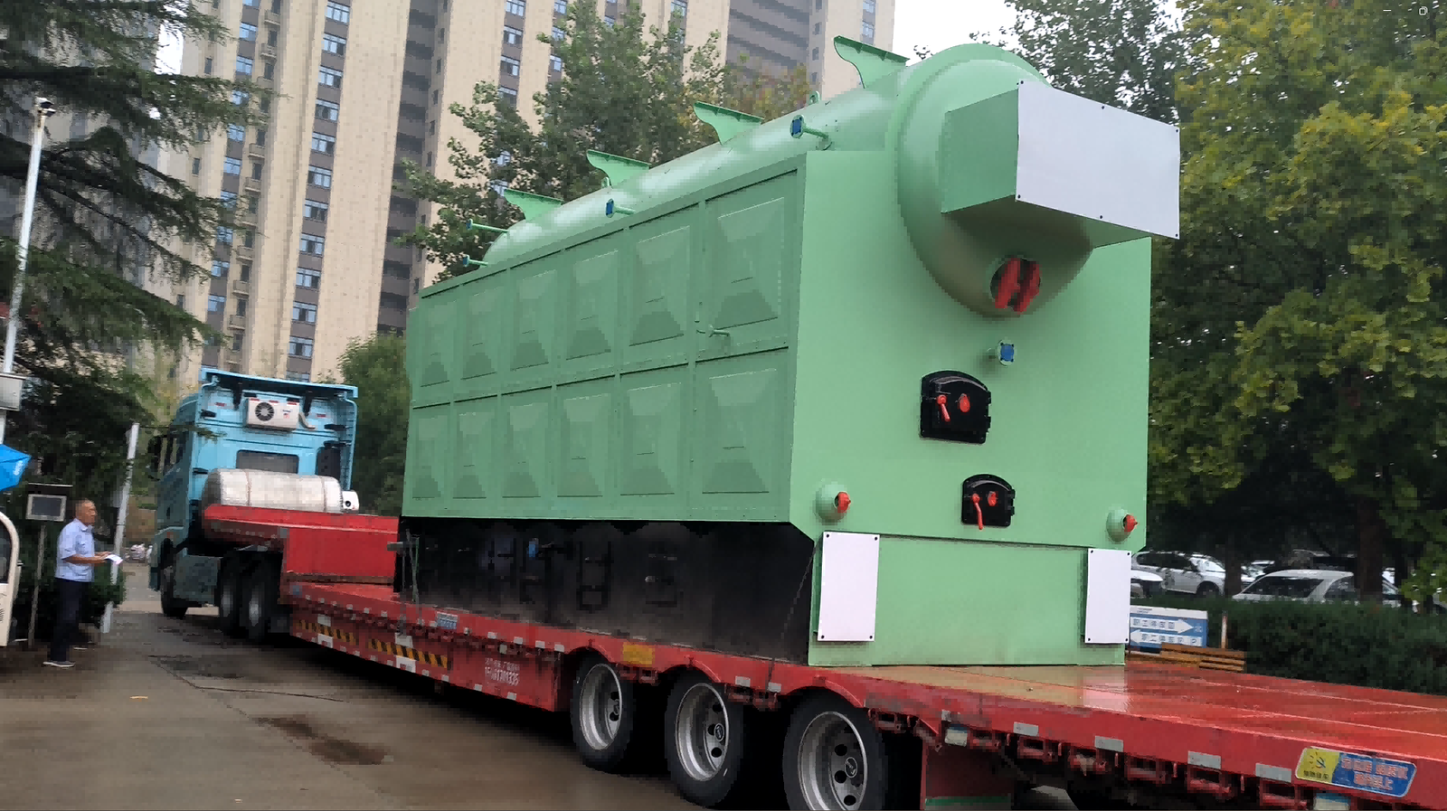
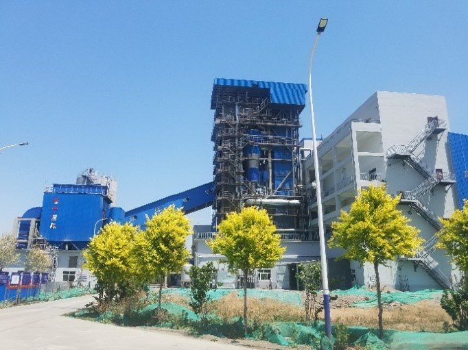
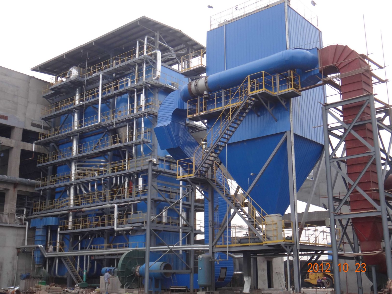
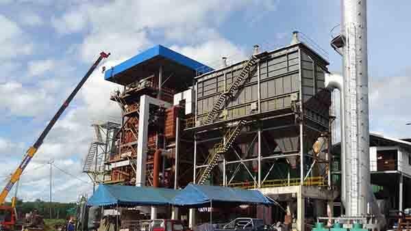
-scaled.jpg)