
How Is the Waste Heat Recovery Boiler Market Evolving Globally?
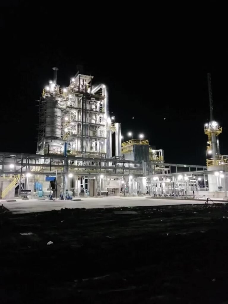
Every megajoule that escapes through an unrecovered flue gas stack is money you’ve already paid for — fuel, combustion air, maintenance on the firing equipment — vaporizing into the atmosphere. In cement kilns, glass furnaces, and non-ferrous smelting lines, exhaust gas temperatures routinely run between 350 °C and 900 °C depending on process stage, and plants that haven’t installed recovery equipment are typically burning 15–40% more fuel than they need to. At current industrial gas and coal prices, that gap translates quickly into six- or seven-figure annual losses on a mid-sized production line. The waste heat recovery boiler — WHRB — isn’t a peripheral add-on; it’s increasingly the difference between a plant that can compete on operating cost and one that can’t.
The global waste heat recovery boiler market was valued at roughly USD 6.8 billion in 2023 and is projected to reach approximately USD 11.2 billion by 2031, growing at a CAGR of around 6.4%. Industrial sectors — cement, steel, glass, petrochemicals, and non-ferrous smelting — account for over 65% of demand, with Asia-Pacific holding close to 48% of global market share, driven primarily by industrialization in China, India, and Southeast Asia.
What’s genuinely interesting right now is that the market growth isn’t uniform, and the reasons plants are finally committing to WHRB projects have shifted in the last few years. Carbon compliance pressure, grid instability driving on-site steam generation, and tighter payback expectations from procurement teams are all reshaping which configurations get specified and which geographies are moving fastest. The picture looks different in a Southeast Asian greenfield plant than it does in a European retrofit, and understanding that split is where the real procurement and engineering decisions live.
WHRB Technology Typology: Matching Boiler Configuration to Exhaust Gas Conditions
Selecting the wrong WHRB configuration is not a minor engineering oversight — it leads to accelerated tube erosion, chronic fouling, unplanned shutdowns, and in the worst cases, a complete retrofit within five years of commissioning. The selection logic starts with the exhaust gas itself: temperature, volume, dust loading, and chemical composition. Everything else follows from those inputs.
Fire-Tube (Smoke-Tube) Units: The Compact, Lower-Pressure Workhorse
In fire-tube WHRBs, hot flue gas passes through tubes submerged in a water shell. The geometry is simple, fabrication costs are relatively low, and the footprint is tight — which is exactly why small cement grinding plants and batch-type glass furnaces often specify them. Practical limits sit around 550 °C inlet gas temperature and steam pressures below 1.6 MPa. Push beyond those bounds and you’re fighting shell stress and tube-to-tubesheet joint fatigue. For a plant needing 2–8 t/h of low-pressure process steam from a diesel generator exhaust or a small rotary kiln, a fire-tube unit is usually the right call. It won’t win efficiency awards, but it’s maintainable by a two-man team.
Water-Tube WHRBs: High-Capacity, High-Pressure Duties
Once you’re looking at large electric arc furnaces, petroleum refinery process heaters, or a steel plant converter gas system, water-tube construction becomes mandatory. These units handle steam pressures from roughly 2.5 MPa up to 10 MPa, with superheated steam temperatures reaching 420–450 °C depending on the downstream turbine specification. Water circulates inside the tubes; gas flows across the bundle. This inversion of geometry allows far higher pressure containment and better accommodation of thermal cycling.
Natural circulation relies on the density differential between water and steam-water mixture — no pump, lower parasitic power, simpler controls. Forced circulation uses a dedicated recirculation pump, which adds complexity and a maintenance point but gives you tighter control over tube wall temperatures and allows more compact drum arrangements. In practice, natural circulation dominates in utility-scale and heavy industrial WHRBs; forced circulation shows up where space constraints are severe or where the heat flux distribution is uneven, as in some smelter off-gas applications.
Gas Path Orientation and Dust Management
Horizontal gas path designs work reasonably well for relatively clean gases. Introduce cement kiln dust at concentrations above 20–30 g/Nm³ and you will plug horizontal tube banks within weeks without aggressive mechanical rapping systems. Vertical downflow orientation — gas entering at the top and falling through the bundle — lets gravity assist dust dropout before it cements onto tube surfaces. Most serious cement and non-ferrous smelter WHRBs specify vertical downflow with rapping hammers or vibrators on each tube row. Skipping this detail in the specification is a procurement mistake that shows up at the 6-month inspection.
Bare Tube vs. Finned Surface Selection
For gas streams carrying significant dust, acid mist, or sticky particulates — or for inlet temperatures above roughly 600 °C — bare tubes are standard. Fins accumulate deposits, accelerate corrosion under the fin base, and become nearly impossible to clean in service. For clean gas streams, serrated or solid helical fins improve the heat transfer coefficient substantially, often allowing a 30–50% reduction in boiler footprint for equivalent duty. Gas turbine exhaust WHRBs (HRSGs) almost universally use finned surfaces because the exhaust is comparatively clean and the economics of a compact unit are compelling.
Single-Pressure vs. Multi-Pressure HRSG for Combined-Cycle Applications
A single-pressure drum captures heat across a limited temperature band. If the gas turbine exhaust enters at 520–560 °C and exits the HRSG at, say, 150 °C, a single-pressure design leaves significant low-grade enthalpy on the table. Multi-pressure configurations — typically two or three drum circuits at high, intermediate, and low pressure — allow the steam cycle to follow the exhaust gas temperature profile more closely, recovering exergy that would otherwise go up the stack. The efficiency gain over single-pressure can be 8–14 percentage points depending on the turbine rating and local steam demand profile, which at utility scale justifies the additional capital and instrumentation cost.
Thermal Oil WHRBs: When Steam Isn’t the Right Answer
Not every plant wants steam. Asphalt mixing plants, certain chemical reactors, and food processing lines often need heat at 200–320 °C with zero tolerance for high-pressure systems — whether for safety permitting reasons, operator skill constraints, or process sensitivity. Thermal oil (heat transfer fluid) WHRBs solve this neatly: the fluid circulates at essentially atmospheric pressure on the process side, the heat transfer oil absorbs exhaust gas energy, and the plant gets controllable, pressureless heat delivery. Fluid degradation and the fire risk of hot oil leaks are real maintenance concerns that get underweighted at the procurement stage.
Multi-pressure HRSG configurations improve heat recovery efficiency by 8–14 percentage points compared to single-pressure designs in gas turbine combined-cycle applicationsTrue
This range is consistent with published combined-cycle thermodynamic analyses; actual improvement depends on turbine exhaust temperature, steam pressure levels, and local heat sink conditions — not a fixed number but a credible engineering estimate
What Engineers Must Specify Before Approaching a Supplier
Any WHRB quotation that arrives without these inputs locked down is guesswork: exhaust gas flow rate in Nm³/h at the actual operating condition (not just design peak), inlet gas temperature, dust concentration in g/Nm³, gas composition including SO₂, HCl, and moisture content for acid dew-point calculations, required steam pressure and temperature or thermal oil outlet temperature, permissible flue gas pressure drop across the boiler, and the expected turndown ratio if the upstream process runs at variable load. Dew-point corrosion from condensing sulfuric or hydrochloric acid destroys tube surfaces within months if the economizer exit gas temperature is not maintained above the calculated dew point — typically 130–160 °C for sulfur-bearing gases, higher if HCl is present. This is where low-quality specifications cause expensive failures.
Regional Market Dynamics: Where WHRB Investment Is Accelerating and Why
Asia-Pacific: Policy-Driven Demand With Real Teeth
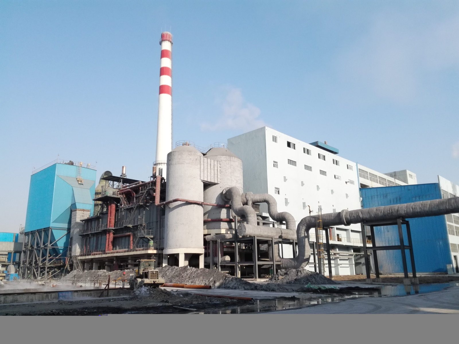
The Asia-Pacific region holds roughly 48% of global WHRB demand, and that share is not softening. China remains the anchor. Under GB/T 17167 and the associated mandatory waste heat power generation requirements for new dry-process cement lines above a certain clinker capacity, plant owners don’t get to debate whether to install a WHRB — the question is which configuration and who supplies it. In practice, this has pushed Chinese cement groups to accumulate significant operational experience with AQC (air quenching cooler) and SP (suspension preheater) boiler combinations, often recovering enough enthalpy to offset 25–40% of a plant’s grid power draw depending on clinker throughput and cooler design. That’s not a marginal gain; it changes the plant economics fundamentally.
India operates differently but with growing urgency. The Perform Achieve Trade (PAT) scheme under the Bureau of Energy Efficiency penalizes designated consumers — cement, steel, aluminum, textiles — for exceeding their specific energy consumption targets. Plants that don’t hit reduction milestones face escalating compliance costs. In my experience reviewing project inquiries from Indian cement operators, the PAT cycle deadlines drive procurement timing more than anything else. Plants rush procurement in the 18–24 months before a PAT cycle closes. Expect lumpy demand patterns, not smooth growth.
Vietnam and Indonesia are a different story — less regulatory push, more raw capacity expansion. Industrial park development in the Mekong Delta corridor and Java’s manufacturing zones is adding new glass, ceramics, and light metals capacity that simply wasn’t there five years ago. These are greenfield installations where WHRB spec is set at the EPC bidding stage, not retrofitted later. That’s actually easier from an engineering standpoint, but procurement timelines can be aggressive and local infrastructure for commissioning support is still maturing.
Middle East and Africa: Refinery Integration Taking Priority
Natural gas abundance in the Gulf has historically suppressed interest in heat recovery — why bother when fuel is cheap? That calculus is shifting, slowly but measurably. Saudi Vision 2030 and UAE Net Zero 2050 are starting to redirect capex toward energy integration projects that previously couldn’t clear internal hurdle rates. Refineries adding or upgrading CDU/VDU units and sulfur recovery units are now routinely specifying WHRBs as part of the heat integration package rather than treating them as optional add-ons. Flue gas temperatures from Claus unit thermal reactors, for instance, can run 900–1,200°C at the inlet — well within range for generating medium-pressure steam at 3–6 MPa for process use or power.
Saudi Vision 2030 and UAE Net Zero 2050 commitments are beginning to redirect refinery capex toward heat integration projects including WHRBsTrue
Both national programs explicitly target industrial energy intensity reduction and carbon footprint; refinery operators under Aramco and ADNOC supply chains have reported increased heat recovery project approvals since 2022 as part of Scope 1 and Scope 2 reduction roadmaps.
Africa outside the Gulf-adjacent corridor is still primarily project-by-project — cement kilns in East Africa and North Africa represent the clearest near-term opportunity, usually financed through development bank instruments with specific energy efficiency conditionalities.
Europe: Highest Regulatory Pressure, Most Demanding Specs
European buyers operate under EU ETS carbon pricing that has ranged EUR 60–90/tonne CO₂ over the past two years, which changes the math on heat recovery investments sharply. A steel melt shop or glass furnace that was borderline on WHRB justification at EUR 25/tonne suddenly looks very different at EUR 75. The Industrial Emissions Directive and REPowerEU targets layer on top of that.
The more interesting development is WHRB integration into electric arc furnace off-gas recovery. EAF waste gas exits at 1,000–1,400°C with highly variable flow — not an easy duty cycle for a boiler. European steel groups pursuing decarbonization roadmaps are specifying EAF off-gas WHRBs with rapid-response steam drum designs and robust sootblowing systems to handle the dust loading. Waste-to-energy plants across Germany, the Netherlands, and Scandinavia have been running WHRBs in corrosive, chloride-laden flue gas environments for decades now, and that operational knowledge base shapes what European buyers expect in terms of material specifications — typically austenitic stainless or Inconel cladding in the superheater zone.
PED 2014/68/EU compliance is non-negotiable for pressure vessel equipment sold into the EU. European procurement teams will ask for the Notified Body documentation early and will not substitute third-party inspection with manufacturer self-certification. Suppliers who underestimate this requirement routinely lose deals late in the negotiation.
North America: Incentive-Driven Acceleration
The U.S. Gulf Coast petrochemical and refining corridor has run WHRBs on reformer and cracker flue gas streams for decades — this is not a new technology to operators in Texas and Louisiana. What’s changed is the financial environment. The Inflation Reduction Act’s investment tax credits for industrial energy efficiency, specifically the Section 48C advanced energy manufacturing credit and the Section 179D commercial energy efficiency deduction as applied to industrial facilities, are creating project economics that justify heat recovery installations that couldn’t previously clear approval internally. Rough estimate from conversations with EPC contacts: IRA credits can reduce effective installed cost by 20–30% depending on project structure and tax position, which moves a marginal project into definite go territory.
Cement majors pursuing ENERGY STAR certification for plant operations also represent a consistent demand thread. ASME Section I certification for the boiler and NBIC compliance for installation are baseline requirements — not differentiators, just minimum table stakes.
Latin America: TCO Arguments Over Carbon Framing
Brazil and Mexico account for the bulk of Latin American WHRB activity, concentrated in cement and long steel production. The regulatory environment here leans softer than Europe, so the sales argument is almost entirely economic: what does this unit cost over 15 years including fuel offset, and what’s the payback at current energy tariffs? Project financing constraints are real — many plants in this region rely on development bank loans or equipment financing from export credit agencies, which introduces conditions and timelines that purely commercially financed projects don’t face. Suppliers who can support local financing structures or work within ECA frameworks tend to win over those who can’t, even if the technical proposal is similar.
A practical note on procurement culture: Asian and Middle Eastern buyers increasingly require committed spare parts localization, local agent service capability, and confirmed DCS/PLC integration compatibility — often specifying Siemens S7, ABB, or Honeywell systems by name in the tender. European and North American buyers tend to prioritize third-party certification trails and performance test protocols over brand preferences in controls. Treating these markets identically in proposal preparation is a reliable way to lose on points you didn’t need to lose on.
Industry-Specific WHRB Applications: Engineering Parameters Across Cement, Steel, Glass, and Petrochemical Sectors
The 65%-plus share that cement, steel, glass, petrochemicals, and smelting hold in global WHRB demand is not a coincidence — each sector produces large, relatively steady exhaust streams at temperatures and flow rates that make heat recovery genuinely economical. But the engineering requirements diverge sharply between them. A configuration that works well behind a cement preheater will fail quickly in a glass furnace application if the designer hasn’t accounted for the gas composition differences. Sector knowledge matters here more than generic boiler theory.
Cement: Dual-Boiler Configurations and High Dust Loads
A typical dry-process cement line at 5,000 tpd clinker output operates two distinct waste gas streams: preheater exit gas at roughly 280–380°C (depending on preheater stage count and raw material moisture) and clinker cooler exhaust at 200–280°C. The industry-standard response is a two-boiler arrangement — an SP (suspension preheater) boiler on the hot end and an AQC (air quenching cooler) boiler on the cooler end — feeding a shared steam turbine generator. Together, these typically recover 6–10 MWe of electrical power per line, though the actual output depends heavily on clinker capacity, local altitude, and how well the cooler is tuned.
Dust loading is the dominant mechanical challenge. SP boiler inlet gas carries 60–80 g/Nm³ of fine kiln dust, which settles aggressively on tube banks if gas velocity drops below roughly 8–10 m/s. Hopper geometry, continuous screw conveyor extraction, and tube pitch selection (usually wider-than-standard to reduce bridging risk) are non-negotiable design elements, not optional upgrades. Skimping on hopper volume is a common cost-cutting mistake that leads to plugging within the first wet season.
Specific steam generation in cement WHRB systems typically runs 0.8–1.5 kg of steam per kg of clinker produced, the wide range reflecting preheater configuration and cooler efficiency. Payback periods for well-engineered systems sit around 2.5–4 years at current industrial electricity prices in most markets.
Steel, EAF, and Sintering: Managing Extreme Temperature Transients
Electric arc furnace off-gas is a different problem entirely. Peak temperatures of 1,400–1,600°C make direct WHRB exposure impossible; a water-cooled duct hood (essentially a primary radiant cooler) is mandatory to bring the gas down to 600–800°C before it enters the convective WHRB sections. The heat load is also intermittent — it follows the EAF tap-to-tap cycle — so the boiler design needs sufficient steam drum volume to buffer the swings without pressure cycling that fatigues tube welds.
Sintering machine WHRBs face a different constraint: SO₂ concentrations in the flue gas require the boiler outlet temperature to stay above the acid dew point, typically above 160°C for sulfurous flue gas mixtures. Running cooler than that to squeeze more heat out will cause cold-end corrosion that can destroy an economizer section in one to two operating seasons.
Sintering WHRB systems must maintain flue gas outlet temperatures above the acid dew point to prevent cold-end sulfuric acid corrosion.True
Sulfur trioxide (SO₃) in sintering flue gas combines with moisture to form sulfuric acid vapor. Below the acid dew point — generally 130–160°C depending on SO₃ concentration — condensation on economizer and air preheater surfaces causes rapid corrosion. This is well-established in industrial combustion engineering practice.
Glass Furnaces: Downstream SCR Integration
Regenerative glass melting furnaces discharge flue gas at 400–550°C, which is a manageable temperature range, and dust loading is relatively low compared to cement or sintering. The complication is NOₓ — glass furnaces are heavy emitters, and in most regulated markets, an SCR unit now sits upstream of the WHRB. The SCR catalyst window (typically 300–400°C) dictates where in the flue gas train the WHRB can begin recovering heat, and the designer has to preserve enough gas temperature at SCR inlet to keep the catalyst active.
Recovered steam from glass WHRB installations usually runs 1.0–2.5 MPa, suitable for batch preheating, plant space heating, or utility steam header supply. It is rarely high enough grade for power generation without supplementary firing.
Petrochemical and Refinery: Pressure Drop Is King
Behind a gas turbine in a combined-cycle petrochemical cogen, the WHRB (functioning as an HRSG) must not impose more than roughly 500 Pa of gas-side pressure drop across the convective section. Exceeding that limit back-pressures the turbine and degrades its output — sometimes enough to offset the thermal benefit of the heat recovery entirely. This is a constraint that shapes the entire tube bank design: fin pitch, rows per pass, and flow velocity all get driven by pressure drop budget, not just thermal duty.
Sulfuric acid plant tail gas WHRBs recover heat from converter exit gas at 450–500°C. The design here focuses on material selection for the tube-side fluid and careful control of gas temperature leaving the boiler, since the downstream absorption tower has its own temperature requirements.
MSW Incineration: Corrosion Is the Life-Limiting Factor
Municipal solid waste grate incineration produces flue gas at 850–950°C after the post-combustion chamber, entering a radiation-pass boiler section before the convective WHRB. European WtE plant standards generally target 4.0 MPa / 400°C superheated steam — enough for reasonable turbine efficiency while limiting superheater tube metal temperatures.
Chlorine, from PVC and other chlorinated waste fractions, drives high-temperature corrosion on superheater tubes through a cycle involving HCl, alkali chloride deposition, and accelerated metal wastage above roughly 450°C tube wall temperature. The practical response is either Inconel 625 weld overlay on the leading superheater passes, or accepting a steam temperature ceiling that keeps tube metal temperatures in a safer range. Both strategies add cost; the choice depends on local waste composition and the plant’s risk tolerance for unplanned outages.
Payback periods across MSW and energy-from-waste applications tend to be longer — 4–6 years is realistic — partly because the capital cost of corrosion-resistant materials is significant and partly because gate fees rather than energy revenue often drive the project economics in the first place.
Key Engineering Challenges in WHRB Design: Fouling, Corrosion, Pressure Drop, and Availability
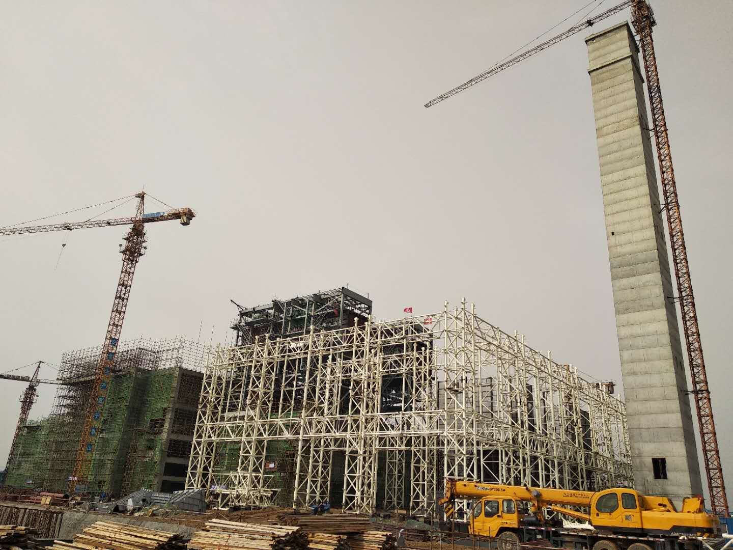
A WHRB that looks good on paper at commissioning and then quietly degrades over the next eighteen months is one of the more frustrating outcomes an EPC team can hand a plant owner. The root causes are almost always the same handful of problems — fouling, cold-end corrosion, erosion, and thermal fatigue — and none of them are exotic. They’re just underestimated.
Tube Fouling: The Silent Efficiency Drain
Sticky dust is the primary villain in cement kiln and EAF off-gas applications. Alkali sulfates from cement pre-heater exhaust condense onto tube surfaces in a semi-molten state and then harden into deposits that a simple rapping system won’t touch. Zinc oxide fume from electric arc furnace off-gas behaves similarly. In practice, heat transfer coefficients can drop 15–35% over a three-to-six month interval if there’s no effective online cleaning strategy in place — and that translates directly into reduced steam output and a steam balance hole that the plant didn’t plan for.
The selection between acoustic soot blowers and steam lance (retractable) soot blowers is not academic. Acoustic systems work reasonably well on dry, light fly ash, and they avoid the moisture introduction that can cause localized corrosion. Steam lance blowers have more mechanical authority against bonded deposits but require steam extraction from the drum circuit, add a maintenance item, and can cause thermal shock on thin-wall tubes if the lance pressure or spacing isn’t controlled properly. For cement kilns with heavy alkali sulfate fouling, most experienced engineers default to steam lance blowers on the first two passes and acoustic systems further downstream where the dust is cooler and less sticky.
Acid Dew-Point Corrosion: Getting the Cold-End Thermal Design Right
Sulfuric acid dew point in flue gas containing SO₃ sits roughly in the 130–160°C range for moderately sulfurous fuels; high-SO₃ streams from non-ferrous smelters or certain heavy fuel oil applications can push that threshold up toward 180°C. The critical rule is straightforward — keep minimum tube metal wall temperature above the dew point — but achieving it in real hardware takes more thought than the rule implies.
Insulating the economizer casing is a start, not a finish. Bypass dampers that allow partial flue gas routing around the cold section during startup (when wall temperatures are still climbing) matter just as much. Controlled blowdown timing to prevent stagnant saturated water sitting against cold tube walls is another layer that gets cut from maintenance procedures under time pressure, then causes a corrosion surprise six months later.
Maintaining tube wall temperature at least 10–15°C above the calculated acid dew point is the standard design margin for WHRB cold-end protection.True
This margin accounts for local gas temperature variation and measurement uncertainty, and is consistent with guidance in EN 12952 and common WHRB design practice for sulfur-containing exhaust streams.
High-Temperature Erosion in Dust-Laden Gas Streams
Erosion rate scales roughly with the cube of gas velocity — which means going from 10 m/s to 14 m/s at a tube inlet zone isn’t a 40% problem, it’s closer to a 175% problem. Design targets for bare tube sections typically run 8–12 m/s on the gas side; inlet transition zones where dust is still entrained and velocity is uneven need additional protection. Chromized tube shields, ceramic tile liners, and deflector plates at the gas inlet are the standard toolkit. Skipping the deflector plates to save fabrication cost is a decision that usually pays for itself in tube replacement within two to three years, sometimes faster in high-dust EAF applications.
Thermal Cycling Fatigue in Intermittent-Operation Plants
Batch glass furnaces and EAF steelmaking introduce a challenge that continuous-process plants largely escape: repeated thermal cycling. Drum and header walls that see 200°C swings multiple times per week accumulate fatigue damage at welds and nozzle penetrations. ASME Section I and EN 12952 both specify allowable heating and cooling rates — typically somewhere in the range of 50–100°C per hour for drums of moderate wall thickness, though the actual limit depends on drum diameter, wall thickness, and material grade. Plants that ignore these ramp rates because the furnace operator wants a faster restart are buying future cracking risk.
Boiler Availability and Maintenance Planning
World-class cement WHRB installations hit annual availability above 95%. That’s achievable, but it requires that outage windows are planned around kiln shutdown schedules, not treated as independent maintenance events. A WHRB pulled offline for tube bundle inspection during a period of kiln operation is pure production loss, and it’s avoidable with coordinated planning. Modular tube bundle designs that allow a replacement bundle to be staged outside and swapped in within 48–72 hours are worth the upfront design cost in any plant running tightly scheduled production.
Instrumentation and Control Integration
The WHRB control system must be subordinate to the primary process — full stop. Drum level control needs fast response, typically under 10 seconds for feedwater valve actuation, because gas flow upsets from the primary process (a kiln feed interruption, an EAF tap) propagate quickly to steam generation rates. Automatic bypass damper actuation on process upset protects both the drum and the tube bundles from steam starvation or overpressure. DCS integration via 4–20 mA, HART, or Profibus should be specified in the contract scope, not treated as a site engineering task — mismatched signal protocols discovered during commissioning are a reliable source of startup delay.
Competitive Landscape and Procurement Criteria: How Global Buyers Evaluate WHRB Suppliers
Serious WHRB tenders are not won on price alone — and they rarely go to the lowest bidder when the project involves high-pressure steam, continuous process integration, or a site where unplanned downtime costs more per day than the buyer’s entire annual maintenance budget.
The Tier Structure Most Buyers Already Know
European and Japanese OEMs — BORSIG, Nooter/Eriksen, Kawasaki Heavy Industries, Mitsubishi Power — occupy the top tier largely on the strength of decades of HRSG references in combined-cycle power and complex petrochemical service. Their pricing reflects it: for a multi-pressure HRSG above 6 MPa, expect a significant premium over Chinese competition, sometimes 30–60% higher on capital cost depending on scope. That premium is often justifiable when the flue gas stream is corrosive, the steam conditions are genuinely extreme, or the buyer’s lender requires a name that’s already on a bankable project list.
Chinese manufacturers, Taishan Group among them, have moved well past the “cheap copy” perception in most markets. The more credible ones now hold ASME S and U stamps, carry expanding PED certification portfolios, and have delivered to Southeast Asia, the Middle East, and Africa with local commissioning teams. The gap in references is closing, particularly for single-pressure WHRBs in cement, glass, and non-ferrous applications — segments where the flue gas conditions are well-understood and the design is mature.
There is still a middle tier of regional fabricators in India, Turkey, and South Korea that win on price and local content rules. Their quality is uneven. In practice, buyers who have gone that route on a 15 MW+ project often come back with a story about weld rework during commissioning or a steam drum that didn’t pass hydrostatic test first attempt.
Certifications That Actually Gate Market Access
ASME S and U stamps are non-negotiable for North American projects and for many Middle Eastern EPC contracts that specify ASME VIII Div. 1 construction. Getting them is not just paperwork — it requires an authorized inspection agency witnessing fabrication, documented material traceability, and a quality system that survives an ASME audit. Buyers should verify stamp validity dates; a lapsed stamp means the shop cannot legally stamp new vessels.
For European projects, PED 2014/68/EU Module H (full quality assurance) or the B+D route (type examination plus production quality assurance) governs pressure equipment. Indian projects typically require IBR (Indian Boiler Regulations) registration, which involves submission to the Chief Inspector and can add 8–14 weeks to project schedule if not started early. ISO 9001 is a baseline expectation everywhere now — necessary but not sufficient.
ASME S and U stamps require ongoing surveillance audits and can be suspended if fabrication quality falls below code requirements.True
ASME stamps are issued under a quality control program that Authorized Inspection Agencies audit periodically; non-conformances can result in suspension, making stamp validity a legitimate procurement verification point.
Total Cost of Ownership: The Framework Buyers Should Be Using
Capital cost typically runs 40–55% of 20-year TCO. The rest is energy offset value (30–40%, depending heavily on local fuel or electricity pricing), maintenance and spares (10–15%), and unplanned downtime — which is the number most procurement teams underweight. A single forced outage on a cement kiln or steel reheat furnace can cost USD 50,000 to 250,000 per day in lost production, depending on plant scale and product margin. A WHRB that saves USD 400,000 on capital but introduces one extra unplanned shutdown per year often destroys that saving inside 18 months.
What Full EPC Scope Actually Means
Buyers increasingly specify single-source WHRB packages rather than splitting supply between a boiler vendor, an instrumentation contractor, and a civil subcontractor. The logic is sound: interface risk between an economizer flange and a BOP piping contractor who used a slightly different nozzle schedule has caused more commissioning delays than most people admit. A full package — steam drum, superheater, economizer, deaerator, blowdown vessel, bypass damper, ESP or bag filter interface, BOP piping, and DCS panel — puts responsibility in one place.
Factory acceptance testing should include hydrostatic pressure testing at 1.5× design pressure per ASME or EN 12952/12953 requirements, radiographic and ultrasonic examination of Category I welds, and dimensional verification against certified drawings. Material traceability documentation — mill certificates matched to individual pressure parts — is not optional on any serious project; it protects the buyer in the event of a future inspection or insurance claim.
After-sales support for overseas projects is where the gap between suppliers often shows up most painfully. A 12–24 month defect liability period means little if the OEM cannot dispatch a commissioning engineer within two weeks of first steam raise. Spare parts holding agreements for critical wearing components — bypass damper drives, drum level instruments, sootblower mechanisms — and remote monitoring via IoT-enabled sensors are becoming standard expectations rather than value-adds. Buyers evaluating suppliers from outside their home region should ask directly: who is your local service partner in our country, and can we speak to a plant that used them?
Integration of WHRBs into Circular Energy Systems: Combined Heat and Power, ORC, and Steam Turbine Configurations
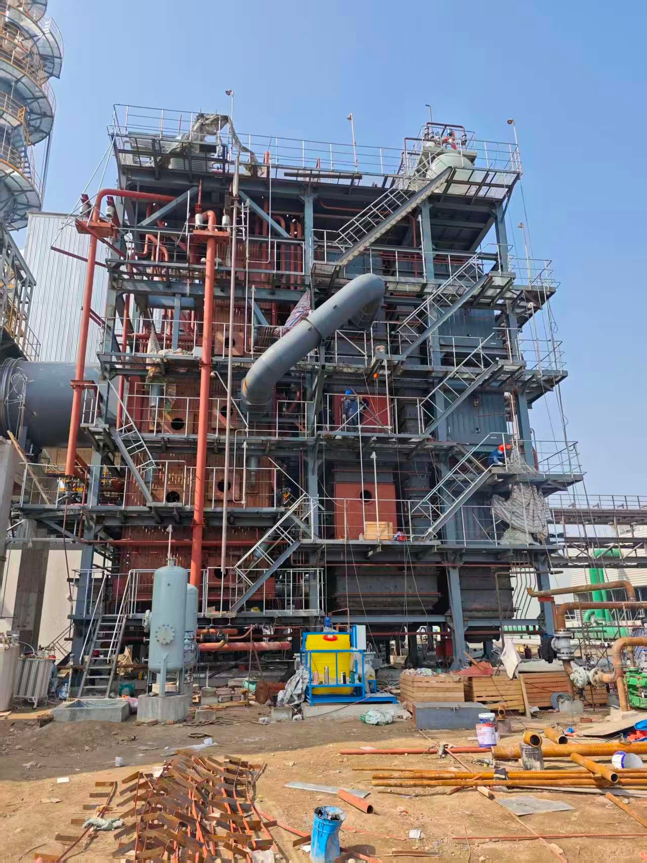
A WHRB that terminates at a steam header is leaving money on the table. The real value proposition — the one that closes capital justification for most plant owners — comes when the recovered heat feeds into a layered energy system where steam, power, cooling, and feedwater preheat all interact. Getting that integration right requires engineering judgment that sits well outside the boiler scope itself, which is why EPC contractors increasingly expect suppliers to speak this language fluently.
Steam Turbines: Back-Pressure vs. Condensing, and Why It Matters
The most widely deployed configuration in cement and float glass plants pairs a WHRB with a back-pressure steam turbine. Steam enters at roughly 3.5–6.0 MPa and 380–450°C, expands through the turbine, and exhausts at a pressure that still carries usable heat — typically 0.3–0.6 MPa — directly into the process steam network. You generate electrical power and satisfy process heat demand simultaneously, which makes the energy balance favorable almost regardless of electricity tariff. Generation efficiency from the steam cycle typically lands in the 18–28% range, depending on steam conditions, turbine stage count, and how well the condenser (if present) is maintained.
Condensing turbines make more sense when process steam demand is low or intermittent — some petrochemical sites and standalone power blocks fall into this category. You maximize power output, but you abandon the low-grade heat, so the overall site energy recovery rate drops. In practice, most industrial plants are better served by back-pressure machines unless their steam load factor falls below roughly 40% on an annual basis.
A pressure-reducing valve bypass is always installed in parallel. That’s not optional — it’s the availability insurance. But running the PRV as the primary path instead of the turbine is an operational habit that quietly hemorrhages revenue. Turbine investment is generally justified once average steam throughput exceeds approximately 5 t/h on an annualized basis; below that, the payback period stretches past what most project finance committees will accept.
ORC for Low-Temperature Exhaust Streams
Not every exhaust stream justifies a steam system. Glass lehrs, food-processing ovens, smaller non-ferrous operations — these often produce flue gas in the 150–300°C range, occasionally lower. Organic Rankine Cycle modules handle this territory. Working fluids like pentane, toluene, or various silicone oils have lower boiling points than water, enabling power generation from heat sources as cool as 90°C in some configurations, though 150–250°C is the practical sweet spot for most commercial ORC units.
Module sizes run from around 200 kWe up to roughly 5 MWe. They are self-contained, skid-mounted, and require considerably less site civil work than a steam turbine island. The tradeoff is higher specific cost per kWe and working fluid management — some fluids are flammable, others degrade over time, and a supplier who glosses over that in the proposal is one to scrutinize carefully.
Absorption Cooling: Turning Low-Pressure Steam into Refrigeration
Single-effect LiBr absorption chillers typically need steam at 0.4–0.8 MPa. Double-effect units require slightly higher pressure but deliver a COP around 1.2–1.4 versus roughly 0.7 for single-effect, so the choice depends on steam availability and cooling load magnitude. Adoption has accelerated noticeably in Southeast Asian industrial parks — Thailand, Vietnam, Indonesia — where a plant simultaneously has abundant low-grade waste heat and a substantial year-round cooling load. Converting that steam into chilled water instead of dumping it through a pressure control valve is essentially free cooling once the absorption plant is paid for.
Cascade Design: Closing the Loop
The highest overall recovery rates come from cascade arrangements where the WHRB primary output — high-pressure steam — drives a turbine for power, the economizer secondary output produces pressurized hot water at 90–130°C for feedwater preheating or district heating, and a condensate return system closes the water-energy loop back to the boiler. Cascade designs, when properly engineered, can recover 85–92% of available waste heat in the flue gas stream. That figure depends heavily on feedwater inlet temperature, minimum stack temperature constraints (acid dew point being the hard floor), and whether the plant has a genuine heat sink for the lower-grade output.
Grid Interaction and Project Economics
WHRB-based captive power typically offsets grid purchases at industrial tariff rates of USD 0.08–0.18/kWh in most emerging markets, though the range is wide and depends on country, utility contract structure, and time-of-use pricing. Some jurisdictions — increasingly in South and Southeast Asia — permit surplus power export under net metering or wheeling arrangements. Where that’s available, it can improve project IRR by 2–4 percentage points, which is often the difference between a marginal and a clearly bankable project.
Back-pressure steam turbine configurations paired with WHRBs can simultaneously generate electrical power and supply low-pressure process steam, improving overall site energy utilization compared to condensing turbine or PRV-only configurations.True
Back-pressure turbines exhaust at a pressure usable for process steam, recovering both mechanical energy (converted to electricity) and residual thermal energy in the exhaust steam, whereas a PRV wastes the pressure differential entirely and a condensing turbine sacrifices the low-grade heat to the condenser.
The honest summary: a standalone WHRB recovers heat. A WHRB integrated into a properly designed CHP, ORC, or cascade system recovers heat and generates value across multiple energy vectors simultaneously. The engineering complexity is real, but so is the difference in project returns.
Emission Compliance and Environmental Performance of WHRB Systems
Regulatory compliance has quietly become the deciding factor in whether a WHRB project gets permitted, financed, and built on schedule — or stalls in the environmental review stage for a year. Getting the boiler thermal design right is necessary but no longer sufficient. The flue gas treatment train, the bag filter material spec, the SCR window, the dioxin burnout zone — these all interact with WHRB configuration in ways that catch underprepared engineering teams off guard.
WHRBs as Partial NOₓ Reducers — and Their Limits
There is a persistent misconception worth addressing directly: WHRBs do reduce the potential for thermal NOₓ formation downstream, because by extracting heat from the exhaust they lower the stack outlet temperature. That matters. But the NOₓ already formed in the primary combustion or process furnace is not destroyed by passing through a heat recovery boiler. The gas exits cooler, not cleaner.
WHRBs inherently destroy NOₓ already present in flue gas through the heat recovery processFalse
WHRBs lower flue gas temperature and reduce further thermal NOₓ formation potential downstream, but they do not remove NOₓ already generated in combustion. Dedicated SCR or SNCR systems are required for NOₓ removal.
For SCR integration, the catalyst activation window is typically 280–420°C — narrower in practice than suppliers sometimes suggest, and sensitive to dust loading and SO₃ poisoning. If the WHRB cools the gas below that window before the SCR, you either need to reheat (which destroys your energy recovery economics) or place the SCR upstream of the WHRB, between the process and the boiler inlet. That upstream placement works for cement clinker cooler exhaust and steel EAF off-gas, but it demands a high-dust SCR design with wide-pitch catalyst modules — roughly 20–25 mm pitch rather than the standard 6–9 mm used in clean-gas applications. The capital cost difference is real, usually 30–60% higher for the SCR unit alone.
SNCR is less sensitive to temperature placement but achieves lower NOₓ reduction efficiency, typically 40–70% versus 80–95% for SCR. For installations targeting EU IED BAT-AEL limits in the cement sector — NOₓ at 200–450 mg/Nm³, dust at 10–20 mg/Nm³, SO₂ at 50–200 mg/Nm³ — SNCR alone is often marginal, particularly for older rotary kilns running variable feed. The WHRB designer needs that emissions compliance conversation to happen before the boiler heat balance is fixed, not after.
Particulate Matter Control and Bag Filter Compatibility
WHRB outlet gas temperature directly determines which particulate control technology is feasible. Electrostatic precipitators handle higher temperatures more comfortably, but fabric filters — specifically pulse-jet bag filters — achieve lower dust outlet concentrations, often below 5 mg/Nm³, which is where the IED dust BAT-AEL sits for new cement installations.
The constraint is bag material. Standard fiberglass bags are rated to roughly 260–280°C continuous, with short excursion tolerance above that. PTFE membrane bags run reliably to about 240°C but cost noticeably more — expect 3–5× the bag price compared to woven fiberglass, depending on bag geometry and supplier. If your WHRB outlet temperature fluctuates above those limits during startup or load swings, bags fail fast and the particulate exceedances trigger permit violations, not just maintenance costs.
In practice, most WHRB designs targeting bag filter downstream integration include a conditioning zone — either a natural cooling section, a spray cooler, or an air dilution damper — to hold outlet temperature in the 180–220°C band. That temperature band also avoids acid dewpoint condensation for most sulfur-lean gas streams, though it needs re-evaluation for streams with SO₃ concentrations above roughly 15–20 ppm.
SO₂ Management and Cold-End Corrosion
Sulfur-bearing gas streams — from non-ferrous smelters, petrochemical process heaters, and certain coal-fired waste heat applications — create a specific corrosion risk at the cold end of the WHRB economizer. When local tube wall temperatures drop below the acid dewpoint (typically 130–160°C for SO₃-containing gases, depending on moisture and SO₃ partial pressure), sulfuric acid condenses on tube surfaces and destroys carbon steel in months rather than years.
The standard response is material selection at the economizer cold end: CorTen steel (weathering steel, SPA-H grade) performs reasonably for mildly acidic condensation; duplex stainless — 2205 or similar — is warranted for more aggressive conditions. Some operators use a steam coil air preheater to keep feedwater inlet temperature above the dewpoint, which protects the economizer without upgrading tube metallurgy. Either route adds cost, but the alternative — replacing an economizer section every 18 months — is worse.
Wet FGD or semi-dry scrubbers for SO₂ removal sit downstream of the WHRB in most configurations, after the dust collector. The sequencing matters because FGD operates at lower gas temperatures where SO₂ absorption is more efficient and where spray-quench equipment isn’t fighting against high-enthalpy inlet gas.
MSW Incineration: The 850°C, 2-Second Rule
Municipal solid waste incineration WHRBs operate under the strictest emission regime of any sector covered here. The EU Waste Incineration Directive, now absorbed into the updated IED BAT conclusions, requires that post-combustion flue gas be held at a minimum of 850°C for at least two full seconds before entering the WHRB radiation section. For gas streams containing more than 1% chlorinated compounds by weight, the minimum temperature rises to 1,100°C.
This 850°C requirement exists specifically to ensure thermal destruction of dioxins and furans (PCDD/F), which must reach the final stack at below 0.1 ng TEQ/Nm³. The WHRB inlet temperature for MSW applications is therefore constrained from below, not just from above — the boiler cannot be designed to start recovering heat so aggressively that it pulls gas below 850°C before the two-second residence criterion is satisfied. That typically means the radiation pass of an MSW WHRB is physically longer and less densely tubed than in comparable industrial applications, and the overall boiler footprint grows accordingly.
Carbon Accounting: WHRB Contributions to Scope 1 and Scope 2
This is an area where the documentation discipline often lags the engineering reality. A WHRB generating electricity that displaces grid power reduces a plant’s Scope 2 emissions — but only if the accounting correctly attributes that displacement using the applicable grid emission factor, which varies from roughly 0.05 kg CO₂/kWh (hydro-heavy grids) to over 0.85 kg CO₂/kWh (coal-heavy grids). The same recovered output has radically different carbon credit value depending on where the plant is located.
WHRB steam replacing output from a natural gas-fired package boiler eliminates direct fuel combustion at that boiler, which is a Scope 1 reduction. Under ISO 14064-1 and the GHG Protocol Industrial Standard — which most CDP respondents and ESG-reporting manufacturers now follow — the avoided emissions calculation requires metered WHRB output, a documented baseline for the displaced source, and an uncertainty statement. Plants that run WHRBs but haven’t metered the thermal output separately from the primary process are leaving verifiable carbon reduction credits undocumented, which increasingly matters when buyers and financiers are asking for third-party verified GHG inventories.
The engineering team specifying a WHRB should, at minimum, flag the metering and data-logging requirements to the plant’s sustainability function early — steam flow measurement, power output metering, and system boundary definition are not expensive to include at project stage, but they become awkward and costly retrofits later.
Project Execution and EPC Delivery: From Feasibility to Commissioning in International WHRB Projects
Getting a waste heat recovery boiler from concept to commercial operation in an overseas plant is rarely as clean as the project schedule suggests. There are compressible phases and incompressible ones, and confusing the two is where most delays originate.
Feasibility: What the Numbers Actually Need to Be Worth Trusting
The single most common mistake at concept stage is sizing a WHRB against a single steady-state flue gas measurement — often taken during a plant visit when the process happens to be running at peak load. In practice, cement kilns, electric arc furnaces, and glass tanks all cycle. Continuous process gas monitoring over a minimum of 30 operating days, capturing start-up ramps, load reductions, and seasonal fuel switches, is the only way to define a representative design envelope.
From that data you build a heat balance model, derive a preliminary WHRB sizing (surface area, drum geometry, pass arrangement), and produce a capital cost estimate. At concept stage, ±30% accuracy is honest and defensible for an investment approval gate. Anyone offering ±10% at this point is either guessing or has already pre-committed to a configuration the process data doesn’t yet support. Simple payback at this stage typically runs 2–5 years depending on local energy prices, plant operating hours, and whether recovered steam displaces fuel-fired generation or grid electricity — state that dependency explicitly in the feasibility report or the finance team will argue about it later.
Engineering Sequence: The Documents That Actually Control Fabrication Quality
Basic engineering delivers the PFD and P&ID, equipment data sheets, and the pressure part design calculations. Whether you’re working to ASME Section I or EN 12952 matters for wall thickness, ligament efficiency, and nozzle reinforcement calculations — and those choices lock in early because they govern which material certificates (MTRs) the mill needs to supply. Pressure part design is not something to finalize after procurement starts; the sequence runs the other way.
Detailed engineering adds the general arrangement drawings, 3D model with clash detection run before fabrication release, and nozzle loading reports for every process connection. A mislocated 150 NB steam outlet that conflicts with a structural beam costs almost nothing to fix in the model and roughly 3–6 weeks of rework if caught during site installation.
Fabrication Hold Points: Where Third-Party Inspection Actually Earns Its Fee
Material certification (mill test reports for all pressure parts), WPS and PQR approval, progressive NDE — radiography on butt welds, PWHT documentation — and pre-shipment hydrostatic testing are the baseline. Hold points witnessed by TÜV, Bureau Veritas, or Lloyd’s Register should be specified in the contract, not left to the manufacturer’s discretion. In my experience, the hydrostatic test is rarely the problem; it’s the PWHT records and radiograph rejection rates mid-fabrication that signal whether a shop is actually controlling quality or just planning to fix things at site.
Steam drums for mid-sized WHRBs run 15–30 tonnes. Combined with tube bundle sections and headers, you’re almost always dealing with heavy-lift road transport from port to site, and in Southeast Asia or East Africa that route survey is not optional. Oversized load permits can add 4–8 weeks to logistics lead time in some jurisdictions. Fumigation-free steel-frame skidding rather than untreated timber is worth specifying for any tropical destination — phytosanitary rejections at port are an unpleasant way to lose two weeks. Ocean freight from Chinese manufacturing ports to the Middle East or West Africa typically runs 25–45 days; budget the outer number for scheduling purposes.
Pre-Commissioning and the Tests That Actually Validate Performance
Site hydrostatic testing at 1.5× design pressure, instrument loop checks, safety valve setting with witness — these are sequential, not parallel. Refractory lining in radiation sections (standard for cement kiln and MSW-coupled boilers) needs full cure time before heat-up begins, and that schedule dependency is routinely underestimated.
Drum heating rate during cold start should be kept below 60°C per hour for thick-wall drums to prevent thermal stress cracking.True
This limit is consistent with industry practice derived from thermal fatigue analysis of heavy-wall pressure vessels; exceeding it during initial heat-up is a documented cause of drum shell cracking and has been referenced in EPRI and boiler OEM commissioning guidelines.
Steam purity sampling — Na⁺ and SiO₂ against IAPWS targets — tells you whether the pre-operational steam line flushing was adequate before you expose any downstream turbine or process equipment to boiler water carryover. The performance acceptance test measures steam output, steam temperature, exit gas temperature, and pressure drop against guaranteed values under agreed reference conditions. If those reference conditions aren’t pinned down in the contract before commissioning, disputes about whether the boiler “met spec” under a slightly off-design gas flow are almost inevitable.
The handover package — as-built drawings, O&M manuals in the working language of the site operations team, and a categorized spare parts list with lead times — is often the deliverable that gets rushed. It shouldn’t be. A plant that loses its as-built nozzle schedule during an expansion project three years later will wish someone had insisted on a complete documentation handover at the start.
Frequently Asked Questions About Waste Heat Recovery Boilers
These questions come up repeatedly in tender discussions, site audits, and procurement meetings. The answers below reflect how these decisions actually play out in the field, not how they look in a brochure.
What is the difference between a WHRB and an HRSG?
The terms get conflated constantly, including by experienced people who should know better. HRSG — heat recovery steam generator — refers specifically to the boiler positioned downstream of a gas turbine in a combined-cycle power plant. It’s designed around a relatively clean, high-volume exhaust stream at 450–600°C, usually with duct burners for supplementary firing. WHRB is the broader category: any boiler recovering enthalpy from industrial process exhaust — cement kiln preheater exit gas, electric arc furnace off-gas, glass furnace flue gas, and so on. An HRSG is technically a WHRB, but not every WHRB is an HRSG. In procurement documents, using HRSG when you mean a cement kiln WHRB will generate technically incorrect proposals, because the tube arrangement, dust-handling geometry, and soot-blowing requirements are fundamentally different.
What minimum exhaust conditions justify a WHRB investment?
As a rough working rule: sustained gas temperatures above roughly 250°C combined with flow rates that can generate at least 1–2 t/h of recoverable steam are where the economics start to make sense. Below that threshold — say, 180–220°C exit gas from a well-optimized process — you’re usually better served by an economizer or an air preheater rather than a full steam-generating circuit. The actual cut-off depends on local energy prices, steam demand patterns, and whether you’re targeting power generation or direct process heat. At USD 0.10/kWh and above, the bar drops a bit. At USD 0.05–0.06/kWh, you need a stronger case.
How long does a WHRB last, and what wears out first?
Design life is typically 20–25 years, assuming adequate water treatment and a reasonable maintenance program. That 25-year figure isn’t guaranteed — it depends heavily on flue gas dust loading and composition. The critical consumable items are tube shields and refractory liners in the inlet section, hopper liners in settling chambers, and soot blower nozzles. In a high-dust cement application, plan on replacing tube shields every 3–5 years. In a cleaner petrochemical or gas-based exhaust environment, you might stretch that to 7–8 years. The waterside is equally important: tube failures from scale or corrosion are entirely preventable, yet they’re one of the most common causes of unplanned shutdowns.
Can you retrofit a WHRB without an extended production shutdown?
Yes, in most cases — but it takes planning. Prefabricated modular sections and bypass damper systems allow hot tie-in during a scheduled maintenance stop on the kiln or furnace. For a single-module cement WHRB retrofit, a 15–30 day installation window is realistic, provided civil foundations and interconnecting pipework are completed beforehand during normal production. Trying to compress that window further usually creates quality problems. The bypass damper is non-negotiable: it protects primary production continuity if the WHRB needs to be isolated for inspection or repair.
What water quality does a WHRB require?
This is where plant operators frequently underestimate the requirement. For WHRBs operating above 3.5 MPa, feedwater conductivity should be below 0.2 µS/cm, dissolved oxygen below 7 ppb, and pH held in the 9.0–9.6 range. High-pressure units with austenitic superheater tubes are particularly vulnerable to stress corrosion cracking if chemistry drifts. Scale as thin as 0.3 mm on tube walls measurably reduces heat transfer and raises metal temperatures. Poor water treatment doesn’t just increase maintenance costs — it shortens tube life from 20 years to under 10, and tube replacements in an installed boiler are expensive and time-consuming.
WHRBs operating above 3.5 MPa require feedwater conductivity below 0.2 µS/cm to prevent stress corrosion cracking in superheater tubes.True
This aligns with ASME and GB/T boiler water quality standards for high-pressure steam systems; austenitic stainless steel superheater tubes are particularly susceptible to chloride-induced SCC when water chemistry is poorly controlled.
How do suppliers support projects in remote locations?
The honest answer is that supplier support capability varies enormously, and this question should be asked explicitly during tender evaluation. Reputable full-scope manufacturers ship pre-assembled skid packages to reduce field erection complexity, provide multilingual O&M manuals (not just Chinese or English), station commissioning engineers on-site through the initial operating period, and — increasingly — offer video-link remote diagnostics during the first year of operation. Consignment spare parts stock arrangements, where critical items like soot blower elements, level gauge glasses, and control valve trim are held in-country, make a real difference when you’re 400 km from the nearest industrial supplier.
What payback period should a cement or steel plant expect?
Cement WHRBs recovering power for self-consumption typically achieve a simple payback of 3–5 years at energy prices in the USD 0.08–0.12/kWh range. Steel EAF applications can do slightly better — 2.5–4 years — because steam can carry higher economic value when used for process heating rather than power generation. That said, EAF off-gas is notoriously dusty and chemically aggressive, which raises maintenance costs and can push the real payback toward the longer end of that range. Neither figure accounts for carbon credit revenue, which in some jurisdictions meaningfully improves the economics but shouldn’t be the primary justification for a capital project.
Future Outlook: Green Hydrogen, Carbon Capture, and Next-Generation WHRB Technology Directions
The next decade of WHRB development is not going to be a straight-line continuation of what came before. Several converging pressures — decarbonization mandates, new energy carriers, and genuinely novel materials — are reshaping what buyers will expect from a waste heat boiler by the early 2030s. If you’re sizing a capital budget with a 15-year horizon, these trajectories matter more than current market share figures.
WHRBs as Infrastructure for Green and Blue Hydrogen Pathways
Steel and cement plants produce exhaust streams at 850–1,100°C that currently drive conventional steam cycles. The interesting shift is that some of that recovered steam — particularly high-pressure saturated or lightly superheated steam in the 6–10 MPa range — is increasingly being evaluated as feedstock heat for electrolysis preheating or, in blue hydrogen routes, for steam methane reforming. European decarbonization programs in the steel sector have been explicit about cascading waste heat through hydrogen production steps rather than venting or condensing it. The logic is sound: every megajoule you supply from recovered flue gas is a megajoule you don’t burn upstream.
In practice, integrating a WHRB into a hydrogen production train requires rethinking extraction points and steam pressure profiles. The boiler drum pressure, extraction valve sizing, and steam purity spec all change when the steam consumer is a reformer rather than a turbine. This isn’t insurmountable, but it does mean early-stage project scoping has to involve the hydrogen process engineer alongside the boiler engineer — not as an afterthought.
Carbon Capture Ready Design: Extraction Steam Provisions
Post-combustion capture using amine scrubbing is notoriously steam-hungry. Solvent regeneration typically demands low-pressure steam in the 0.3–0.5 MPa range, at volumes that can represent 15–25% of a plant’s total steam output depending on capture rate and solvent choice. Smart WHRB procurement today is beginning to include extraction nozzle provisions, larger drum connections, and steam header routing that accommodates a future CCS train without cutting holes in pressure vessels later — an expensive and often schedule-killing retrofit.
WHRBs installed in cement and steel plants today can be designed with carbon capture steam extraction provisions at minimal additional capital cost during initial construction.True
Adding extraction nozzles and oversized steam headers during initial fabrication typically adds 2–5% to WHRB cost, versus 15–30% cost penalty for retrofitting extraction capability into an existing pressure vessel under operating plant conditions.
Cement plants are particularly active in this planning. The combination of high-temperature kiln exhaust and process CO₂ from calcination makes cement a priority sector for CCS, and plant owners who are already running WHRBs are asking whether their existing steam systems can be extended. Usually the answer is “partially, but not without rerouting.”
Materials Pushing the Performance Boundary
Oxide-dispersion strengthened alloys and nano-composite coatings are moving from research papers toward actual fabrication shops, though slowly — qualification cycles for pressure vessel materials are long for good reason. The practical payoff is superheater tube operation at metal temperatures above 620°C without the creep degradation rates you’d accept as normal with conventional austenitic grades. For MSW and hazardous waste boilers, where radiation pass temperatures are punishing and chlorine-induced corrosion is relentless, ceramic matrix composite tube inserts are being trialed in the hottest zones. Thermal cycling durability is still the open question.
Digital Twins and Predictive Fouling Management
IoT instrumentation on modern WHRBs — tube metal thermocouples, differential pressure sensors across each gas pass, continuous drum water chemistry monitors — is generating enough data that machine learning models can now predict fouling accumulation rates with reasonable accuracy. The operational consequence is meaningful: instead of running soot blowers on a fixed timer (which erodes tubes whether they need cleaning or not), adaptive algorithms activate blowers only when the pressure drop or temperature delta signals actual deposit buildup. In heavy-fouling applications like cement or municipal solid waste, this can extend tube life by a rough 10–20% while cutting steam consumption for blowing by a similar margin. Depends heavily on fuel variability, but the direction is clear.
Modular Platforms Shortening Project Cycles
Custom-engineered WHRBs have traditionally required 12–16 months of engineering lead time. The emerging modular approach — standardized platforms at roughly 5, 10, 20, and 30 MWt capacity steps — is compressing that toward 6–9 months for straightforward applications. Spare parts interchangeability across multiple plant sites is the underrated benefit: a maintenance manager running three plants with identical tube bundles and drum configurations can hold a single shared inventory instead of stocking three separate sets of slow-moving parts. For multi-site industrial groups, this changes the procurement conversation from unit price to lifecycle cost.
Policy Tailwinds That Are Not Optional
The EU Carbon Border Adjustment Mechanism, effective from 2026 on a full basis, directly penalizes energy-inefficient production in export-oriented sectors. For a steel or cement producer selling into European markets, unrecovered waste heat is no longer just an efficiency gap — it’s a cost embedded in the CBAM calculation. World Bank and Asian Development Bank financing programs for industrial energy efficiency are also expanding, particularly in South and Southeast Asia, which tends to unlock projects that were previously stuck at the feasibility stage. G7 and G20 industrial decarbonization pledges create the regulatory architecture; CBAM and development finance create the commercial pressure that actually moves capital budgets. The combination is accelerating adoption faster in export-dependent economies than in domestically-focused ones, which is worth factoring into any regional demand forecast.
References
Energy Efficiency 2025 — Industry — International Energy Agency (IEA)
Improving Industrial Waste Heat Recovery — International Energy Agency (IEA)
Recovery and Reuse of Waste Heat in Eco-Industrial Parks — United Nations Industrial Development Organization (UNIDO)
Waste Heat Recovery in the Cement Process — International Finance Corporation (IFC)
Waste Heat Recovery in Turkish Cement Industry — World Bank
Heat Recovery Steam Generator Services — GE Vernova
Benson Technology — Heat Recovery Steam Generators — Siemens Energy
Heat Recovery Steam Generators (HRSG) — Mitsubishi Power
Greening the Steel Sector in India — Roadmap and Action Plan — Ministry of Steel, Government of India
CIRQLAR — Transforming Waste Heat into Sustainable Power — European Climate, Infrastructure and Environment Executive Agency (CINEA)
How Is the Waste Heat Recovery Boiler Market Evolving Globally? Read More »