
What Are the Key Steps in Installing an Industrial Coal-Fired Boiler?
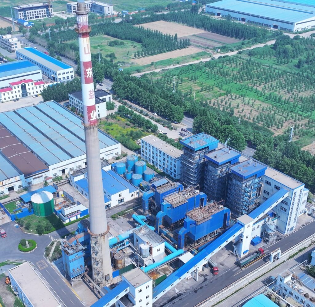
A poorly sequenced boiler installation doesn’t just cause delays — it creates compounding problems that follow the plant for years. Refractory cracked during the first firing because the cure cycle was rushed. Steam drums that passed shop inspection fail hydrostatic tests on-site because the connecting pipework introduced stress during fit-up. Foundation settlement under a 130 t/h unit that was sized for a smaller predecessor. Every one of these failures is recoverable, but none of them is cheap, and some will take a unit offline for six to twelve weeks at the worst possible time.
Installing an industrial coal-fired boiler involves eight to ten sequenced stages: site civil preparation and foundation work, boiler body erection, refractory lining and a controlled 48–96 hour curing cycle, pressure-part welding and inspection, hydrostatic testing at 1.25–1.5× design pressure, auxiliary system integration (fuel handling, ash removal, FD/ID fans, water treatment), electrical and instrumentation tie-in, cold commissioning, refractory dry-out firing, and finally load-ramping to full operation under a formal commissioning protocol.
What most project schedules underestimate is how tightly these stages depend on each other — skip or compress the wrong one, and you don’t just lose time on that step, you potentially invalidate work already completed downstream. The sequence matters as much as the individual tasks, and the reasoning behind each step is worth understanding before the first steel column goes in the ground.
Site Survey, Foundation Engineering, and Civil Works for Coal-Fired Boiler Installation
Before a single structural bolt gets torqued, the civil package either sets you up for a smooth 20-year operation or buries problems that surface at the worst possible time — usually during a capacity ramp-up or a regulatory inspection. This phase gets underestimated on tight-budget projects, and it shows.
Soil Investigation and Load Calculation
A geotechnical survey isn’t optional. You need to know actual bearing capacity, not what the site owner thinks it is. For industrial coal-fired boilers in the 10–130 t/h steam output range, foundation design typically demands 150–300 kN/m² bearing capacity — the lower end applies to smaller package boilers on competent ground, while a 75 t/h or larger water-tube unit with coal bunker, FD/ID fan sets, and steel structure combined can push well past 250 kN/m² depending on layout compactness.
Dead loads are the easy part. The dynamic loads from induced draft and forced draft fans surprise people. A single ID fan on a 75 t/h chain-grate boiler can weigh 4–8 tonnes with its motor, but the real issue is vibration transmission — if fan plinths aren’t properly isolated and sized, you get progressive cracking in adjacent slab sections. Conveyor gallery supports add their own eccentric loads, particularly if the gallery spans over the ash pit area. Get all of this into the structural model before the concrete is poured, not as a retrofit calculation afterward.
Foundation Types and Selection Criteria
For a small 10 t/h chain-grate boiler on decent soil (bearing capacity ≥ 150 kN/m²), isolated column footings under the boiler frame and a simple reinforced slab under the pressure vessel are usually adequate. Once you move into the 40–75 t/h range with a steel-structure-supported drum boiler, a raft slab — typically 600–1,200 mm thick depending on spans and loads — becomes the practical default. It distributes load more evenly and simplifies anchor bolt positioning.
Pile-supported mat foundations come into play when surface soils are weak, waterlogged, or subject to differential settlement — which is common in coastal industrial zones and reclaimed land sites in Southeast Asia. For a 130 t/h water-tube boiler, I’ve seen pile lengths of 12–20 m specified even on what looked like acceptable ground, because the geotechnical report revealed a soft clay layer at 6–8 m depth that would have caused settlement under sustained load.
Foundation bearing capacity requirements vary significantly between drum-type and water-tube boilers of the same steam output due to differences in structural weight distribution and support frame geometry.True
Drum boilers often concentrate load through discrete column footings, while water-tube boilers with tall steel structures distribute load across a wider footprint — meaning the peak pressure per unit area can differ substantially even at the same nominal capacity.
Anchor Bolt Templates and Embedded Plates
Anchor bolt positioning tolerances are tighter than most civil contractors expect. A ±2 mm centerline deviation is the typical allowable for boiler base frame alignment — exceed that and you’re shimming, re-drilling, or in bad cases, scrapping embedded plates. Use steel templates fixed to the formwork before pouring, check them twice before the pour, and check again after. Thermal expansion of the formwork in hot weather is a real nuisance and catches crews off guard.
Embedded plates for pipe supports, duct hangers, and soot blower anchor points need to be positioned at the correct elevation simultaneously. Retrofitting missed embedded items into cured concrete is slow and expensive.
Boiler Room Layout and Structural Clearances
Minimum clearances around the pressure vessel aren’t just a comfort factor — they’re usually codified in your local pressure vessel regulation and your insurer’s requirements. Practically speaking, budget at least 1.0–1.5 m on the firing-front side for burner/grate access, 1.2 m minimum on the side walls for tube inspection and valve maintenance, and rear access of at least 1.0 m for economizer and air preheater work. Tighter than that and routine maintenance becomes genuinely hazardous.
Overhead crane rail elevation needs to be confirmed before the structural steel drawings are finalized. Getting the steam drum into position is a one-time lift, but the crane stays relevant for tube bundle replacement and major overhaul lifts across the boiler’s lifetime. Undershooting the hook height by 500 mm forces creative rigging that nobody should be doing with a 12-tonne pressure vessel.
Coal Bunker, Ash Pit, and Conveyor Infrastructure
Coal bunker foundations are often treated as secondary in project scheduling, which creates timeline problems. The bunker silo itself, depending on storage capacity (typically 50–200 tonnes of coal), sits on its own reinforced foundation that must account for the full live load plus seismic factors in applicable zones. The conveyor gallery connecting the bunker to the stoker feed system needs structural integration with the main boiler building — expansion joints between the two structures are mandatory, not optional, or differential settlement cracks the gallery connection within a few years.
Ash pit civil works deserve attention that they rarely get. The bottom ash conveyor pit is a wet, chemically aggressive environment — coal ash leachate is mildly alkaline to acidic depending on coal type, and the pit walls see thermal cycling. Specify waterproofing membrane plus an acid-resistant lining (polymer-modified mortar or epoxy coating at minimum), and make sure the pit drain is sized to handle unexpected water ingress. A flooded ash pit that backfills with wet ash will halt production faster than almost any boiler fault.
Stack foundations require their own geotechnical input. A self-supporting steel stack 30–50 m tall for a 40–75 t/h installation applies both gravity load and significant overturning moment from wind. Don’t allow the civil subcontractor to size it from a generic table — get the actual stack weight and wind load zone data into the calculation.
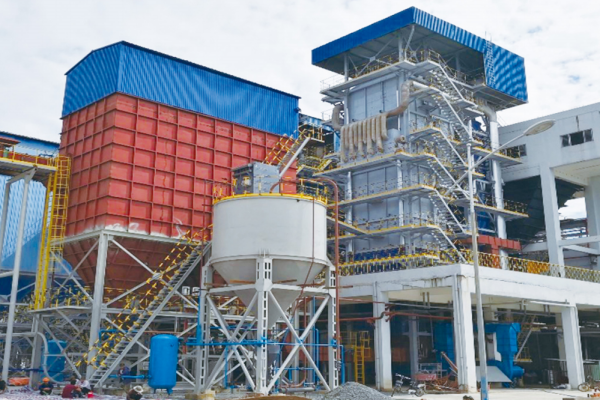 coal-fired boiler project 10
Equipment Receiving, Inspection, and Pre-Assembly Preparation
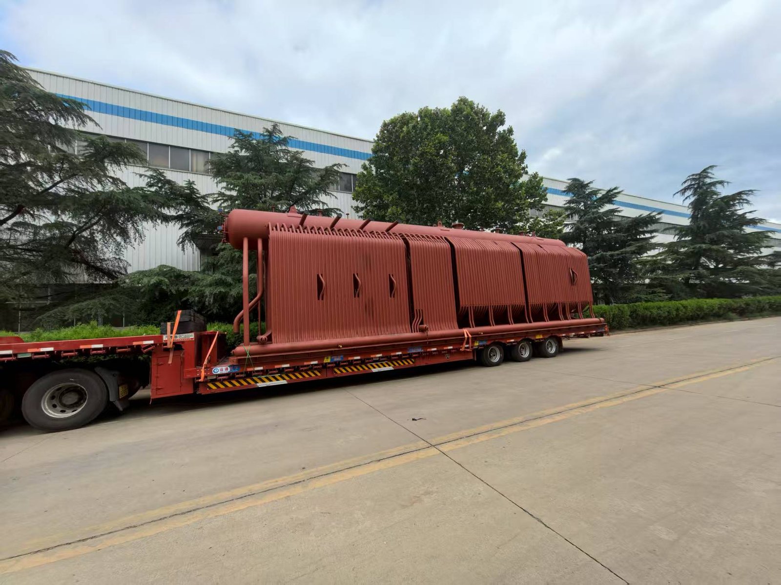
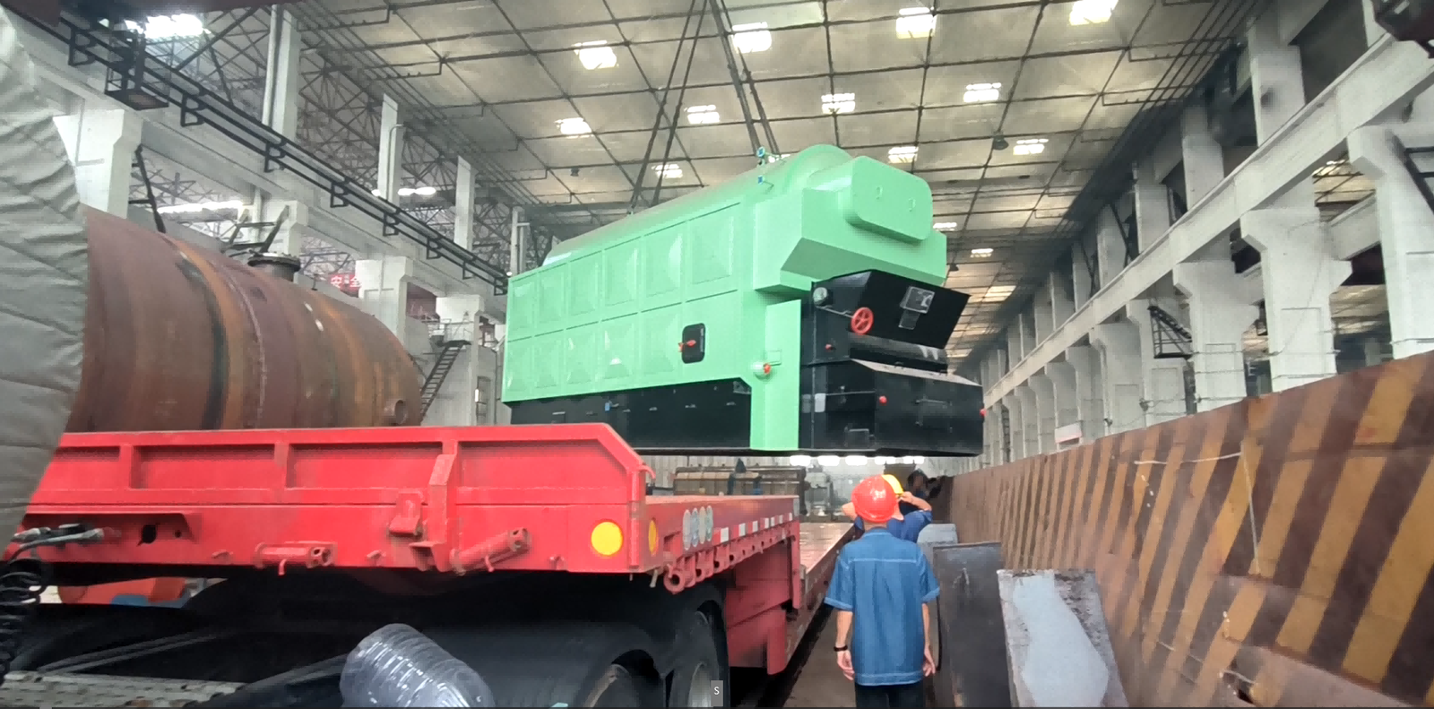
Getting a 25-tonne steam drum off a flatbed and onto the foundation without incident is satisfying. Discovering a dented nozzle or a missing hydrostatic test certificate after the drum is already sitting on its saddles is not. The receiving and pre-assembly phase is where a large proportion of commissioning delays actually originate — not in the erection itself — and it rarely gets the documentation discipline it deserves.
Packing List Verification Against Manufacturing Data Reports
Every major pressure part — steam drums, mud drums, headers, membrane wall panels, economizer coil bundles, superheater elements — should arrive with a corresponding Manufacturing Data Report (MDR) or Manufacturer’s Quality Certificate. Cross-reference each item against the packing list line by line, not just by count. Check that drum heat numbers stamped on the shell match the material test reports in the MDR. Discrepancies between the stamped number and the paperwork are rare but do happen with long supply chains, and catching them before erection saves weeks of re-certification work later.
Membrane wall panels in particular tend to ship in bundles with protective banding that can mask handling damage to fin welds if no one specifically looks. Pull the protective wrapping from a sample of panels and inspect the fin-to-tube weld seam visually. A cracked fin weld that gets sealed behind refractory will become a localized hot spot under load.
Visual and Dimensional Inspection of Pressure Parts
Steam drums should be checked for ovality at the shell cross-section using inside calipers or an ultrasonic wall-thickness gauge. Acceptable out-of-roundness tolerances are defined in the original fabrication drawing — any deviation beyond tolerance needs to go back to the manufacturer before acceptance, not after installation. Tube end condition matters too: flared, burred, or corroded tube ends on economizer coils will prevent proper rolling or welding during assembly and cause leaks that are miserable to find once the unit is insulated and operating.
Weld seam surfaces on pressure drums and headers should show smooth, continuous profiles consistent with the RT/UT results in the MDR. Grind marks, repair weld caps, or color from heat treatment are normal; what you’re looking for is anything that doesn’t match the documented condition.
NDE Records and Hydrostatic Test Certificates
Do not accept pressure parts without the complete NDE package from the manufacturing shop. This means RT or UT reports for longitudinal and circumferential weld seams, hardness test records for any post-weld heat treatment zones, and the hydrostatic test certificate showing the actual test pressure achieved. Per ASME, EN 12952, or GB 150/713 standards depending on your jurisdiction, the shop hydrostatic test typically runs at 1.25–1.5× design working pressure — so for a boiler rated at 3 MPa, expect a test record showing 3.75–4.5 MPa hold, with the duration and inspector sign-off noted.
Shop hydrostatic test certificates can substitute for field pressure testing during commissioning.False
Shop hydrostatic testing verifies the pressure vessel as manufactured, but field hydrostatic testing after erection is required by most jurisdictions and standards (ASME, EN, GB) to verify the integrity of all field-made joints, connections, and the assembled system as installed. They are complementary, not interchangeable.
Auxiliary Component Inventory and Storage
Stoker grate assemblies, air preheaters, cyclone separators on CFB units, soot blowers, and burner components all need condition checks on arrival. For traveling grate stokers, check that grate bar sets are complete and undamaged — replacements for proprietary grate bars can have 8–16 week lead times depending on the supplier, and you don’t want to discover a shortage during erection. CFB cyclone refractory anchor systems ship partly assembled; confirm that anchor hardware counts match the erection drawings before anything gets stored.
Storage conditions are straightforward but routinely ignored under schedule pressure. Pressure parts need dry, covered storage — open-air staging on bare ground, which I’ve seen on more than one site, allows tube bore corrosion to develop within weeks in humid climates. Cap tube ends, block header nozzles, and set components on timber dunnage at minimum 150–200 mm off the ground. Insulating materials, particularly ceramic fiber blanket, are essentially ruined by moisture and must be kept in sealed packaging until installation day.
Pre-Assembly of Sub-Assemblies and Valve Skids
One of the most effective ways to compress the on-site erection schedule — and reduce hot-work exposure hours — is to pre-assemble small-bore piping sub-assemblies and instrument impulse line manifolds before structural steel erection begins. Drain valve clusters, blowdown valve stations, and chemical dosing skids can all be assembled, pressure-tested, and set aside. This shifts welding and fitting work from elevated positions in a partially erected structure (slow, hazardous, expensive) to a clean area at grade level.
Rigging and Lift Planning
Steam drum lifts require a specific lift plan, not a general lift procedure. Industrial boiler drums in the 10–130 t/h range typically weigh somewhere between 8 and 35 tonnes depending on capacity, pressure rating, and whether internals are pre-fitted — the actual certified lift weight must come from the manufacturer’s drawing, not an estimate. Center of gravity location shifts if steam separators or feedwater distribution pipes are pre-installed inside the drum, so confirm the as-shipped internal configuration before finalizing rigging attachment points.
Crane outrigger pad sizing depends on ground bearing capacity — if your civil works phase established a compacted crane pad rated at, say, 180 kN/m², your lift engineer needs that number when specifying outrigger mat dimensions. An undersized pad that settles mid-lift is one of those consequences that’s genuinely catastrophic and entirely preventable.
Structural Steel Erection, Drum Setting, and Pressure-Part Assembly
The erection sequence on a coal-fired boiler is one of those things that looks straightforward on paper and becomes genuinely unforgiving the moment you’re standing in the bay with a 40-tonne drum swinging from a crane. Sequence matters. Skipping ahead — say, dropping the drum before the main columns are fully plumbed and grouted — creates alignment problems that propagate through every downstream pressure-part connection. You will not fix them easily once the membrane walls are in.
Structural Steel Erection: Column Bases to Tie Beams
Start at the column base plates. Before anything is lifted, verify the embedded anchor bolts against the certified foundation drawing — bolt projection, thread condition, and centerline spacing. In practice, even well-executed civil work can put a bolt 5–8 mm off centerline, and catching that before erection saves hours of shimming or slotted-hole remediation later.
Main columns go up first, each plumbed in both planes using precision optical levels or digital inclinometers. The accepted tolerance is column plumb ≤ L/1000 of column height, which on a 12-meter column means no more than roughly 12 mm of lean — but aim tighter than that in practice, because tolerances stack. Platform beams and crane girders come next, then horizontal tie beams that triangulate the frame. Bolt everything to snug-tight before final alignment; full torque comes after the frame geometry is verified across all tiers. Grouting of base plates should use non-shrink cementitious grout and reach minimum cure strength before the drum is set.
Steam Drum Setting
The drum is usually the heaviest single lift on a water-tube boiler — anywhere from 15 tonnes on a small 10 t/h unit to well over 60 tonnes on a 75–130 t/h industrial boiler. Rigging plan, crane capacity with radius margin, and tag-line crew need to be confirmed before the lift, not during it.
Once the drum is lowered onto its saddle supports, check centerline position and axial level before releasing the crane. The drum sits on temporary supports at this stage; permanent attachment to the membrane wall upper headers comes later in the sequence. Do not fully weld or bolt down the drum saddles yet — the drum needs to float slightly to accommodate thermal expansion as the membrane walls are connected.
Membrane Wall Panel Erection and Header Connections
Lower headers are positioned first, set to correct elevation and lateral position, and tack-welded to support brackets. Panel lifting typically goes from the front wall rearward, with each panel’s tube-to-header stub connections cleaned, fit-checked, and beveled before welding begins. Expansion allowance gaps between adjacent panels — usually 6–15 mm depending on panel width and operating temperature — must be maintained precisely. Close them up and you’re building in stress concentrations that show up as cracking in the first two or three thermal cycles.
Upper headers are connected last in the wall sequence, completing the enclosure and allowing the drum saddles to be finalized.
Superheater, Reheater, and Economizer Assembly
Superheater pendant bundles are typically lifted as pre-assembled modules from the fabrication area. Inlet and outlet header connections are field-welded using qualified WPS documents; for alloy steels — T22 (2.25Cr-1Mo) is common in mid-pressure superheaters, P91 shows up in high-pressure or high-temperature applications above roughly 550°C — preheat requirements range from 150°C minimum for T22 up to 200°C or higher for P91. Skip preheat on P91 and you risk hydrogen-induced cracking in the heat-affected zone. It is not a theoretical concern; it happens.
Post-weld heat treatment (PWHT) is mandatory for these alloy joints. For P91, the PWHT window is narrow — typically 730–760°C with controlled ramp and soak times per the applicable WPS. Deviating outside that range either leaves residual stress (too low) or degrades the creep properties the material was specified for (too high).
Economizer modules sit in the rear gas pass. Coil bundle supports are welded to the structural casing, and clearance from the rear pass walls should be verified against the OEM drawing — typically 50–100 mm minimum on each side to allow for differential expansion and future tube inspection access. Cramming the economizer module in tight to save space is a maintenance headache that keeps giving.
Field Weld NDE and Pressure-Part Inspection
Every pressure-part field weld — drum nozzle connections, header stub welds, riser and downcomer connections — needs documented NDE. Radiographic testing (RT) or ultrasonic testing (UT) per ASME Section I or EN 12952-5 are the standard references; which method applies depends on joint geometry, wall thickness, and the applicable code of the destination country. Welder qualification records (WQR) tied to the specific WPS must be on file before any pressure-part welding starts. An inspector showing up on day three of welding asking for WQRs that don’t exist yet is a project-stopper.
Skipping PWHT on P91 alloy pressure welds will not cause immediate failure but guarantees premature creep damage within the first few years of high-temperature operation.True
P91 steel develops its creep resistance through a precisely controlled martensitic microstructure established during PWHT. Without it, residual austenite and insufficient tempering leave the weld and HAZ vulnerable to Type IV creep cracking, a well-documented failure mode in high-temperature power and industrial boiler service.
Stoker Grate and CFB Furnace Internals
On chain grate or traveling grate boilers, the grate frame and drive assembly go in after the lower front and rear headers are positioned — the grate sits inside the furnace envelope, and access becomes awkward fast once the side walls are closed. Drive shaft alignment and grate bar clearance from the side wall seals need to be set before the walls go to full height.
CFB units have a different set of complications. The primary cyclone separators are large, refractory-lined vessels that connect back to the furnace at the top exit. The refractory lining interface at the cyclone inlet duct — where hot furnace gases transition into the cyclone barrel — is a common cracking location if the expansion joint design or the refractory anchoring is wrong. Loop seals (the return leg that feeds separated solids back to the furnace bed) need to be installed with the correct clearance geometry and aeration nozzle orientation per the OEM specification. Getting loop seal geometry wrong affects bed inventory control and combustion stability once you’re running.
Flue Gas Path, Combustion Air Ducting, and Auxiliary Equipment Installation
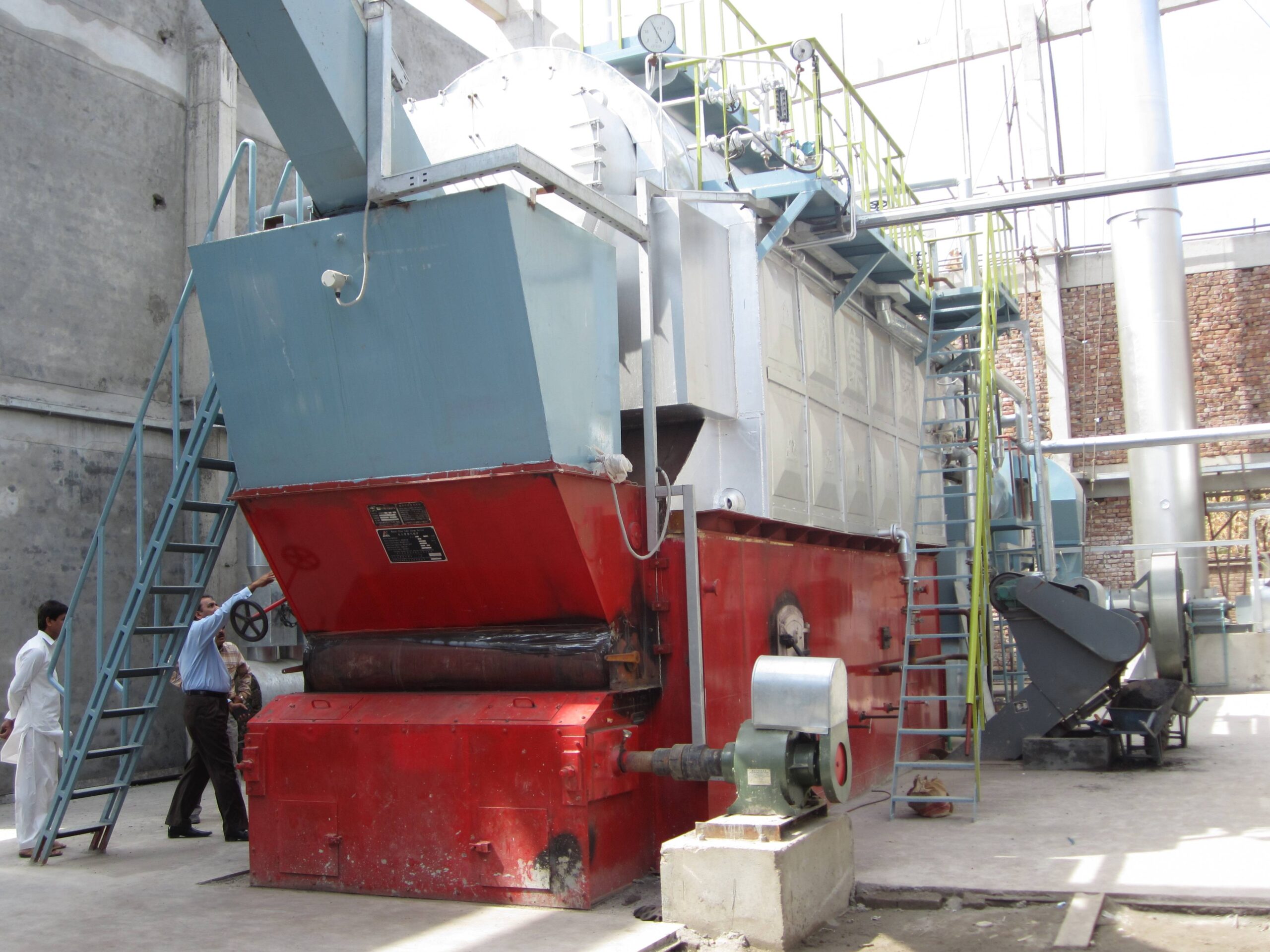
This is, in practice, the section of a coal-fired boiler project where schedule slippage most often originates. The pressure parts get attention. The flue gas and air circuit — the ducts, fans, precipitator, ash conveyors, stack — tends to be treated as secondary until suddenly it’s on the critical path and three subcontractors are waiting on each other.
Flue Gas Ductwork Fabrication and Erection
Duct runs from furnace outlet through economizer, air preheater, and pollution control equipment before reaching the induced draft fan and stack. These are large-bore, low-pressure enclosures, but “low pressure” does not mean forgiving. Gas-tight welded construction is non-negotiable at every joint — a 2 mm gap in a 6-meter duct section doesn’t sound like much until you’re dealing with CO infiltration in an enclosed boiler house, or false O₂ readings that throw your combustion control into chaos.
Internal stiffener rings are typically spaced at 800–1,200 mm intervals depending on duct width and operating temperature; wider spacing on high-temperature zones risks buckling during transient upsets. External insulation support brackets should be welded before insulation is applied, obviously, but I’ve seen sites where contractors installed duct, ran out of time, and tried to weld brackets onto already-insulated sections. It doesn’t go well.
Expansion joints — fabric or metallic bellows — must be placed at every duct-to-equipment connection and at direction changes on runs longer than roughly 12–15 meters. Skipping one to save cost is a common mistake. Thermal expansion on a 40-meter duct run at 350 °C is not trivial; you can crack duct flanges or damage fan inlet cones.
Air Preheater Installation
Rotary regenerative air preheaters (Ljungström type) require careful rotor bearing alignment and, critically, correct sector plate clearance setting at both hot and cold ends. Cold-end clearance is set tighter to limit air-to-gas leakage, but if you don’t account for differential thermal expansion between the rotor and housing — typically 3–8 mm radial growth depending on unit size and operating temperature — you’ll get rotor rubbing at operating temperature, which ranges from annoying to catastrophic depending on how long it runs undetected.
Tubular recuperative preheaters are mechanically simpler but need support frame leveling to within 1–2 mm across the tube bundle footprint. Cold-end acid corrosion is a real concern; specifying enamel-coated or Corten steel tubes for the cold-end rows is worth the cost on high-sulfur coal.
ID Fan, FD Fan, and PA Fan Installation
Fan baseplate grouting is one of those steps that gets rushed. Non-shrink epoxy grout, properly mixed, needs 48–72 hours cure time before shaft alignment begins — skip that and you’ll be realigning after the grout settles under vibration. Shaft alignment for centrifugal fans should be verified by laser alignment to within 0.05 mm radial and 0.03 mm angular tolerance. Soft-foot must be corrected before final tightening; I’ve seen vibration readings that looked like bearing damage turn out to be a 0.08 mm soft-foot condition on a 250 kW ID fan.
Vibration isolation mounts between fan and structural steel are mandatory. Spring isolators are common on larger ID fans (above roughly 160 kW); rubber-in-shear mounts are typically adequate for FD fans and PA fans in the 30–90 kW range.
For CFB boilers, the primary air fan feeds the bed air distribution plate through a windbox. Ductwork connections here must accommodate vertical thermal expansion of the furnace assembly — a fixed rigid connection will crack the windbox flange within a few hundred operating hours.
Laser shaft alignment to 0.05 mm radial tolerance significantly reduces bearing failure rates on industrial boiler fans compared to dial-indicator alignment alone.True
Published bearing manufacturer data and field studies consistently show that misalignment is a primary cause of premature rolling-element bearing failure; laser alignment achieves tighter, more repeatable results than dial indicators, particularly on large-bore shafts where indicator sag introduces measurement error.
ESP and Pulse-Jet Baghouse Installation
Rigid frame erection for an electrostatic precipitator must be plumb and square to within tight tolerances — discharge electrode alignment relative to collecting plates directly determines corona uniformity and collection efficiency. Typical plate-to-electrode centerline tolerance is ±3–5 mm. Rapper mechanism alignment matters just as much; a rapper that strikes off-center will leave ash accumulation on plates, which can bridge and cause short-circuit trips.
For pulse-jet baghouses, bag-to-cage fit is critical. Undersized cages abrade bags; oversized ones allow collapse. Hopper vibrators should be installed on all four hopper walls, not just two — I’ve seen fly ash bridge across a 1.2-meter hopper on high-moisture coal without vibrator assist on the short walls.
FGD System Integration and Stack Connection
Wet FGD systems add significant pressure drop to the flue gas circuit — typically 800–1,500 Pa depending on absorber design — which must be factored into ID fan capacity selection at procurement stage, not after. If ID fan sizing was finalized before FGD was added to the scope (it happens), you may face a fan impeller change or booster fan addition during commissioning.
Dry sorbent injection systems are less demanding on fan capacity but require careful duct injection point location — ideally upstream of the baghouse with adequate mixing length, at least 3–5 equivalent duct diameters before the filter inlet.
Pneumatic fly ash conveying from ESP hoppers or baghouse hoppers to the ash silo requires properly sized rotary airlocks and conveying air pressure typically in the 0.2–0.4 MPa range. Undersized conveying lines block; oversized lines waste compressed air and erode pipe elbows faster than necessary. Ash silo filter vents must be sized for conveying air volume, not just displacement — this gets undersized regularly.
Stack Erection
Self-supporting steel stacks up to roughly 60–80 meters can be shop-fabricated in sections and field-welded or flanged. Guyed stacks are used on taller installations where base moment loads would require an uneconomically thick base section. Either way, acid dew point protection at the liner matters on coal-fired systems — flue gas SO₂ and moisture combine to form H₂SO₄ condensate below roughly 120–150 °C depending on sulfur content, and unlined carbon steel stacks corrode through in 3–7 years under those conditions. Borosilicate glass-lined or acid-resistant brick liner sections at the cold end of the stack are standard practice for high-sulfur coals.
Steam, Water, Blowdown, and Safety Valve Piping Installation
High-pressure piping is where a lot of otherwise well-executed boiler installations quietly fall apart — not during hydrostatic testing, but six months later, when a steam leak appears at a superheater outlet flange or a blowdown line vibrates loose from its support bracket. Getting this right requires treating the piping system as a structural and thermodynamic problem, not just a plumbing exercise.
Main Steam Line Routing and Thermal Expansion
The main steam line from the superheater outlet header to the turbine stop valve (or process header, for industrial process steam applications) typically runs 15–40 meters in a medium-capacity plant, and every meter of that line will expand under operating temperature. For a line operating at 450°C, you’re looking at roughly 5–7 mm/m of thermal growth in carbon steel — that adds up fast, and an unaccommodated anchor point will put bending moments directly onto the drum or header nozzle.
Ω-loops are the standard solution for runs where layout permits. Where space is constrained — common in retrofit installations or tight boiler bays — axial expansion joints work, but they require proper anchor and guide spacing to prevent buckling. The guide intervals matter: for a DN200 steam line, guides are typically placed at no more than 14–20 pipe diameters apart on either side of an expansion joint, depending on the operating pressure and line weight. Skipping guides to save brackets is a false economy; the reaction forces will find the weakest flange.
Pipe material selection for high-pressure steam lines above 400°C should follow ASME SA-335 P11 or P22 (or equivalent EN/GB grades) — standard carbon steel loses creep strength quickly above that threshold. This is worth verifying on the material test reports during incoming inspection, not assuming from the purchase order.
Feedwater Piping and Control Valve Station
The BFP discharge line runs at maximum pump shutoff pressure — often 20–30% above normal operating pressure — so the line class rating needs to account for that, not just the boiler design pressure. Check valve placement immediately downstream of the BFP is non-negotiable; without it, a pump trip under load can send a hydraulic slug back through the impeller.
For the feedwater control valve station, whether you’re using single-element or three-element control (drum level, steam flow, feedwater flow) changes the instrument tap locations and bypass valve sizing. Three-element control is standard on anything above roughly 20 t/h; below that, single-element is often adequate and simpler to commission. The control valve bypass should be full-bore and sized for manual startup flow, not just maintenance isolation.
Blowdown Piping: CBD, IBD, and Heat Recovery
Continuous blowdown (CBD) and intermittent blowdown (IBD) lines are frequently underengineered on smaller industrial jobs. Both must route to a flash tank sized for the blowdown flow at operating pressure — discharging directly to a drain pit without flash separation is a steam waste and a safety problem. The flash steam from the CBD line can be recovered to the deaerator feedline, which on a 35 t/h boiler at 1.6 MPa can recover heat equivalent to roughly 1.5–3% of fuel input. Not dramatic, but consistent.
IBD lines in particular need check valves to prevent backflow when multiple boilers share a common blowdown header. Cross-contamination between units during simultaneous blowdown is a real operating hazard that rarely makes it into the written procedure until something goes wrong.
Safety Valve Installation
A safety relief valve discharge pipe can be left unsupported as long as the valve body itself is bolted to the drum nozzle.False
Discharge pipe reaction forces during valve lifting can exceed several kN and must be independently supported to prevent bending stress on the valve body and nozzle — unsupported discharge pipes are a common code violation found during third-party audits.
Set pressure verification for SRVs should be done on a certified test bench before installation, not assumed from the nameplate. Per ASME Section I requirements, the first SRV must be set at or below MAWP; additional valves can be set up to 3% above MAWP, with the full accumulation (all valves lifting) not exceeding 110% of MAWP. In practice, the most common error is installing valves with incorrect set pressures because spares from a different boiler were used — always cross-check the data plate against the boiler’s stamped MAWP.
Discharge pipe design often gets improvised on site. It needs a drain pocket at the low point to prevent condensate accumulation (a water slug in a lifting SRV causes valve seat damage and characteristic chatter), independent pipe supports at each change of direction, and a vent or silencer at the terminal point that doesn’t allow rain ingress. The silencer back-pressure must be factored into the valve’s certified capacity — if back-pressure exceeds roughly 10% of set pressure for conventional valves, the relieving capacity is reduced.
Chemical Dosing Injection Points
Phosphate or oxygen scavenger injection quills should be located a minimum of 10 pipe diameters downstream of any elbow or pump discharge bend — closer than that, the turbulence prevents uniform chemical dispersion and you get localized concentration spikes that accelerate local corrosion. The quill tip orientation matters too; point it upstream, against flow, for better mixing. Sample cooler piping for water quality monitoring taps should be routed with a slight continuous slope back to drain so condensate doesn’t pool in dead legs between sampling intervals.
Pipe Supports and Spring Hangers
Resting supports, guides, and anchors need to be laid out from a formal pipe stress analysis — not eyeballed on site. The goal is controlling thermal movement without generating nozzle loads that exceed the boiler manufacturer’s published allowable values. Spring hangers are required wherever vertical thermal growth would otherwise lift a resting support off its shoe; cold-set load versus hot-load difference should be marked on the hanger during installation and verified during first startup.
Hydrostatic Testing of Piping Systems
Per ASME B31.1 Power Piping, the hydrostatic test pressure is 1.5× design pressure, held for a minimum of 10 minutes with no visible leakage. Test boundary documentation — clearly marking which valves are the test boundary isolation points, which relief valves are blanked, and which instruments are removed or bypassed — needs to be formalized before pressurization begins, not figured out on the fly. Venting all high points before pressurizing is basic but frequently rushed. Trapped air compresses; trapped water doesn’t — that distinction is what makes hydrostatic testing safe.
Refractory Installation, Insulation, and Casing Seal-Up
Refractory work gets treated as a finishing task on many project schedules — something you squeeze in between pressure-part assembly and the hydrostatic test. That’s a mistake. Get the refractory wrong and you’ll be pulling casing panels six months into operation to patch a cyclone throat, or worse, tracing a furnace wall hot spot back to a delaminated castable layer that nobody caught during installation.
Zoning the Refractory System Correctly
Not all refractory in a coal-fired or CFB boiler does the same job, so using one product throughout is a false economy. Dense castable (typically 2,200–2,800 kg/m³ bulk density, service temperature up to 1,350 °C) belongs in high-erosion, high-temperature zones: CFB cyclone throats, burner quarl blocks on stoker and chain-grate units, and slag tap areas. These zones need abrasion resistance first, thermal resistance second.
Insulating castable — lighter, more porous, lower thermal conductivity — goes in areas like the backpass casing and lower-temperature secondary cyclone bodies, where your priority is heat retention rather than erosion resistance. Using dense castable there wastes material and adds unnecessary dead weight to the structure. For irregular geometries — tube penetrations, corner fillets around buckstays, areas with compound curves — plastic refractory is the right call. It’s hand-rammed into place and conforms to shapes that a poured castable simply can’t fill cleanly.
Anchor Stud Selection and Layout
Anchors are the part of this system that fails silently. The castable cracks away from a corroded or wrongly-typed anchor long before anyone opens an inspection door. V-anchors (bent wire, typically 3–4 mm diameter stainless steel) work well for thinner linings, roughly 75–100 mm, at moderate temperatures. Y-anchors and hex mesh systems are appropriate for thicker monolithic linings and for zones above 1,000 °C, where differential thermal expansion between the anchor and the castable becomes significant.
In CFB cyclone bodies running at 850–950 °C with fly ash velocities that would sand-blast mild steel in weeks, 310S or 314 stainless anchors are the minimum spec. Mild steel anchors in those zones will corrode and lose mechanical engagement within a couple of years. Anchor pitch is typically 150–200 mm centers, but your refractory supplier’s installation drawing governs — don’t improvise the layout.
Mixing, Casting, and Avoiding Cold Joints
Water-to-castable ratio is one of those things where field crews have strong opinions and most of them are wrong. Too wet and the mix slumps, segregates, and produces a weak, porous lining. Too dry and vibration consolidation is incomplete, leaving voids. Follow the manufacturer’s specified water ratio — usually 8–12% by weight for dense castables — and measure it. Mix in batches small enough to place within 20–30 minutes; in hot weather that window shrinks further.
Vibration casting is strongly preferred over gunning for thick monolithic sections. Gunning produces rebound loss of 15–30% and a less uniform density, though it’s acceptable for repair work or areas where form-setting is impractical. Cold joints — where fresh castable is placed against a partially set surface — are a fracture initiation site. Plan your pour sequence so each continuous section is cast without interruption.
The Drying and Curing Schedule
This is where impatient commissioning timelines cause expensive damage. Castable refractories contain chemically bound water that must be driven off gradually. Rush a cold light-up and steam pressure builds inside the lining faster than it can escape — spalling is the result, sometimes catastrophically.
A workable schedule for a typical 10–75 t/h coal-fired boiler: ambient cure for 24 hours after casting, then low-fire hold at roughly 150 °C for 12 hours, step up to around 350 °C for 8 hours, then a controlled ramp to full operating temperature over the remaining period. Total elapsed time lands in the 48–96 hour range depending on lining thickness and ambient humidity. Thick CFB cyclone linings — 200 mm or more — sit at the longer end of that range. Don’t shorten it to meet a handover date.
Skipping or shortening the refractory drying schedule on a coal-fired boiler will not cause immediate visible damageFalse
Insufficient drying drives steam pressure buildup inside the monolithic castable matrix, causing internal spalling, surface cracking, and lining delamination from anchor studs — damage that may not be visible externally but significantly reduces lining service life and can expose pressure parts to flame impingement.
External Insulation and Casing Cladding
Once the furnace walls are enclosed, external insulation goes on the boiler casing, steam drum, headers, and flue gas ductwork. Mineral wool in the 80–150 kg/m³ density range is the workhorse material here; ceramic fiber blanket is used at higher surface temperatures and for drum and superheater header covers. The performance target is a casing outer surface temperature below 50 °C at 1 m ambient — exceeding that wastes heat and creates a burn hazard for maintenance staff.
Cladding is typically 0.8–1.2 mm aluminum or galvanized steel sheet, seamed and overlapped to shed water. In coastal or humid climates, aluminum is worth the cost premium; galvanized cladding rusts at the cut edges faster than most plant managers expect. Expansion joints in the cladding must align with the expansion provisions in the structure — ignore that and the cladding buckles and splits at the first thermal cycle.
Casing Seal-Up and Expansion Provisions
Buckstay-to-casing weld integrity matters more than it looks. An air leak at a casing panel seam draws cold air into the furnace, disrupts combustion stoichiometry, and accelerates corrosion on the flue gas side. Continuous fillet welds on all casing seams, with dye-penetrant or soap-bubble leak checks on pressurized sections, are standard practice on any job worth the name.
Inspection doors and access hatches need rope gaskets or ceramic fiber rope seals compressed properly at installation — not just bolted tight. Expansion seals between the moving furnace wall and the fixed structural steel frame need to accommodate 15–30 mm of thermal growth on a large boiler, depending on height and operating temperature. Installing these seals with inadequate allowance is a reliable way to crack both the seal and the adjacent casing weld.
Common failure modes in service: vibration-induced cracking in CFB cyclone linings (address with flexible fiber layer between dense castable zones), anchor corrosion in wet flue gas zones downstream of an air preheater (specify acid-resistant anchors, consider a protective coating on the anchor base), and chemical attack from alkali compounds when biomass fuels are co-fired with coal (use low-alkali castable formulations and check with your refractory supplier before the fuel blend changes — this one catches plants by surprise).
Electrical, Instrumentation, and Distributed Control System (DCS) Integration
This phase often gets underestimated in project scheduling. Civil work runs over, pressure-part erection slips two weeks, and suddenly the I&C team is being squeezed to compress a four-week scope into ten days. That is where commissioning problems originate — not in the DCS cabinet, but in rushed field wiring done under pressure.
Motor Control Center and High-Voltage Distribution
The MCC installation sequence matters more than most erection plans acknowledge. For a mid-sized coal-fired boiler in the 35–75 t/h steam range, the induced draft (ID) and forced draft (FD) fans typically run on 6 kV or 10 kV, depending on motor size, while feedwater pumps, conveyor drives, and ash handling equipment sit in the 380–690 V tier. These two voltage classes need physically separate cable trays — minimum 300 mm separation, grounded steel tray with dividers if the same tray bank is unavoidable due to structural constraints.
Cable routing on a coal-fired boiler site is genuinely messy. The boiler building is rarely designed with I&C routing as a priority, so instrument signal cables end up sharing corridors with 6 kV power feeders if nobody enforces the separation rules early. Shielded twisted-pair instrument cables should be grounded at the DCS cabinet end only — grounding both ends creates ground loops that show up as 4–20 mA signal drift, which then looks like a calibration problem and costs hours of unnecessary troubleshooting.
Field Instrument Installation
Pressure transmitters and differential pressure (DP) flow elements need impulse line slopes maintained at a minimum of 1:10 to prevent gas pockets (on liquid services) or condensate traps (on steam and gas services). This sounds obvious. It gets violated constantly when instrument tubing has to dodge structural steel added late in the erection sequence.
Drum level measurement deserves particular attention. A bi-color level gauge gives the operator direct visual confirmation at the drum, but the magnetic level gauge transmitting to DCS is what drives the three-element control loop. Both need isolation valves, equalizing legs, and — on high-pressure drums above roughly 5–6 MPa — condensate pots to protect the transmitter diaphragm. Thermocouple and RTD assemblies on superheater outlet headers and economizer inlet/outlet should be installed with sufficient immersion depth (typically 1/3 to 1/2 of pipe diameter, minimum) or the readings will lag actual fluid temperature during transients.
Coal belt weighers and ash drag conveyor load cells need their own calibration records before DCS integration — a weigher that is 3–5% off propagates directly into air-to-fuel ratio calculations.
Control Valves, Actuated Dampers, and Fail-Safe Verification
Every actuated device needs its fail-safe direction confirmed physically, with air supply disconnected, before loop checkout. The feedwater control valve should fail open — loss of air means maximum water flow, protecting the drum from running dry. Fuel shut-off valves fail closed, always. Verifying this by tag on a drawing is not enough; verify it with the instrument air header isolated, document it, and have the commissioning engineer sign off.
Positioner calibration on modulating dampers (FD fan inlet vane, recirculation gas damper) requires the damper to stroke through 0–100% under actual mechanical load, not just bench-tested. Hysteresis in linkage systems, particularly on older rack-and-pinion pneumatic actuators, will cause limit cycling in auto mode if the positioner gain is set too high.
BMS Wiring and Interlock Logic
The burner management system — or stoker control panel on a chain-grate or travelling-grate unit — is the most safety-critical wiring scope on the project. Master fuel trip (MFT) conditions typically include drum level low-low, combustion air flow low, loss of all flame signals, and feedwater pump trip. Each MFT input circuit should be hardwired into the BMS logic controller, not routed through DCS softlogic. The purge timer (usually 5 air changes of furnace volume, commonly 3–8 minutes depending on furnace size) must be enforced as a timed relay that cannot be bypassed by operator action.
Ignition sequence interlocks — pilot proving, main flame establishment, proven airflow — need witnessed loop checks with the actual field devices energised, not just continuity tests at the panel.
DCS Loop Configuration and PID Tuning
Three-element drum level control (drum level + steam flow feedforward + feedwater flow feedback) is the loop that punishes poor tuning most visibly. At light load, the shrink-and-swell effect on drum level means a poorly tuned loop will swing the feedwater valve aggressively on load changes. Reasonable starting parameters for a saturated drum at 2.5–4 MPa are a proportional gain of 0.8–1.5 and integral time of 60–180 seconds — though the right numbers depend on drum volume, feedwater pump head characteristics, and control valve Cv. Tune it at 40–50% load first, then validate at full load.
Combustion air-to-fuel ratio control on a stoker-fired unit requires coal belt weigher input to be reliable before the loop goes to auto. Running on a fixed air flow bias is acceptable for startup and initial commissioning but should not be left as the permanent operating mode.
Safety Instrumented System and Proof Testing
Where a SIS is specified (IEC 61511 SIL 1 or SIL 2 for overpressure backup on the drum), the SIS I/O must remain physically segregated from the basic process control DCS. Proof-test documentation — functional test of each SIS loop from sensor through logic solver to final element — needs to be completed and signed before the boiler is handed to operations. A common site shortcut is to perform proof tests on paper using design logic, without actually tripping the final element. That documentation will not satisfy a third-party safety audit and creates real liability.
Earthing and Signal Shielding
Equipotential bonding across the boiler steelwork, connected to the plant earth grid, keeps touch voltages safe and reduces common-mode noise on instrument signals. The stack and coal bunker need lightning protection — a ground rod at the base of the stack with a measured earth resistance below 10 Ω is a typical requirement, though local codes vary. Instrument cable shields, as noted above, single-point grounded at the DCS cabinet. Any technician who grounds both ends “just to be safe” is creating a problem, not solving one.
Drum level transmitters installed without condensate pots on high-pressure boilers above 6 MPa will have shortened diaphragm life and potential calibration drift under thermal cycling.True
Elevated steam-side temperatures without condensate pot isolation expose the transmitter diaphragm to temperatures exceeding its design rating, accelerating diaphragm fatigue and seal degradation — a well-documented field failure mode on high-pressure utility and industrial boilers.
Pre-Commissioning Checks, Hydrostatic Testing, and Refractory Dry-Out
By the time you reach this stage, the steel is up, refractory is cured, instrumentation loops are wired, and the temptation to rush toward first fire is real — especially when a project is behind schedule. Resist it. Everything done in the next two to three weeks determines whether this boiler runs reliably for fifteen years or spends its first twelve months generating warranty calls.
Multi-Discipline Punch-List and Mechanical Completion
Before any testing begins, every discipline — civil, mechanical, piping, electrical, I&C — submits a formal punch-list. On most EPC projects this gets categorized as A-items and B-items. A-items are hard stops: missing hydrostatic test documentation, unsupported safety valve discharge stacks, unverified earthing resistance, unlabeled isolation valves on the blowdown circuit. None of these can be open when you apply test pressure. B-items are defects that don’t compromise safety or immediate function — a missing walkway grating panel, a damaged insulation jacket on a low-temperature pipe — and they get cleared during the commissioning period itself.
The mechanical completion (MC) certificate is a formal sign-off that all A-items are resolved. Some clients treat it as paperwork; experienced commissioning managers treat it as a liability shield. Issue it only when it’s genuinely earned.
Alkaline Boil-Out and Chemical Cleaning
Mill scale, pipe dope, machining oils, and weld spatter are present in every new boiler system. Left in place, they cause localized overheating, fouling of economizer tubes, and contamination of steam. The standard procedure is an alkaline boil-out: fill the drum and circuit with a solution of roughly 0.2–0.5% sodium hydroxide (NaOH) and 0.3–0.5% trisodium phosphate (Na₃PO₄) by weight, then circulate at low-fire conditions — typically 15–25% of rated thermal input — for 48–72 hours. The exact duration depends on how contaminated the internal surfaces are; on a 35 t/h field-erected unit with extensive field welding, 72 hours is not excessive.
Blowdown the bottom headers every few hours and sample the blowdown water. When it runs clear and pH drops back toward neutral after cooling, the circuit is clean. Drain completely, flush with demineralized water, and inspect headers if accessible. Do not skip this step on the grounds that the tubes “looked clean” on arrival.
Hydrostatic Pressure Test
Fill the boiler cold with demineralized or treated water, working vent valves at every high point to eliminate air pockets — trapped air compresses and can give a false pass on a slow leak. Test pressure per ASME, EN 12952, or GB standards runs 1.25–1.5× design working pressure; a 3.0 MPa rated boiler gets tested at 3.75–4.5 MPa, where exactly in that range depends on which code governs the project.
Raise pressure slowly — no faster than roughly 0.3–0.5 MPa per minute above 75% of test pressure — and hold at test pressure for a minimum of 30 minutes. Walk every weld seam, tube-to-header joint, manhole, and flanged connection during the hold. Acceptance criteria are unambiguous: no visible weeping, no pressure decay beyond what’s attributable to temperature stabilization, no permanent deformation of any pressure part.
A hydrostatic test at 1.25× design pressure is required before commissioning any new industrial boiler pressure vessel under ASME, EN, and GB standards.True
All three major codes — ASME Section I, EN 12952-6, and GB/T 16507 — specify a hydrostatic test at minimum 1.25× maximum allowable working pressure (MAWP) for new steam generators prior to initial operation.
Safety valves must be bench-tested or popping-tested at verified set pressure before the boiler goes online. On a site steam pop test, be prepared for the noise and the regulatory optics — some plants prefer certified bench-test documentation from the valve manufacturer instead, which is acceptable under most codes as long as the certificate is traceable to the actual valves installed.
Refractory Dry-Out Firing
The refractory installed weeks earlier absorbed moisture from the air, rain infiltration, and the hydrostatic test itself. Fire it wet and you get steam explosions inside the castable matrix — spalling, cracking, and possibly a furnace wall you’re cutting out and replacing at week two of operation.
The dry-out curve typically starts at the lowest stable burner load the combustion system can hold — often 10–15% of full thermal input — and holds there for 8–12 hours. Temperature is then stepped up in increments of roughly 50–80°C per hour, with 2–4 hour soaks at specific hold temperatures (commonly around 120°C, 300°C, and 600°C) to drive off free water, chemically bound water, and allow the binder system to sinter properly. Monitor refractory surface temperature with a handheld infrared thermometer or, better, the embedded thermocouples that should have been installed during the refractory pour. If you see surface temperatures rising faster than the ramp curve allows, cut burner input immediately.
Total dry-out time for a medium-capacity coal-fired boiler (20–75 t/h range) typically runs 48–96 hours depending on refractory thickness and ambient humidity. In tropical climates, or if the unit sat open during a rainy season, budget toward the upper end.
Rotating Equipment Trial Runs and BMS Logic Acceptance
Fans and pumps get a bump test first — a momentary start to confirm rotation direction against the shaft arrow — before any sustained run. Then a 2-hour solo run at no-load or minimum flow, during which you measure bearing temperatures (typically expected below 80–90°C depending on bearing type) and vibration velocity. ISO 10816-3 sets 4.5 mm/s RMS as the alarm threshold for industrial fans in this power class; anything above that before the boiler has even seen coal warrants immediate investigation of alignment, balance, or foundation grouting issues.
DCS and burner management system (BMS) logic acceptance comes last. Inject simulated trip signals — low drum level, high furnace pressure, flame failure — and time the shutdown response. Walk through every interlock on the cause-and-effect matrix with the client’s operations team present. A control loop that trips correctly in a FAT environment but misbehaves on site due to a reversed 4–20 mA signal or an incorrect engineering unit scaling is not a theoretical risk; it happens more often than most commissioning reports acknowledge.
Only when all of these gates are closed — punch-list cleared, boiler cleaned and pressure-tested, refractory dried out, rotating equipment running smoothly, and BMS logic verified — is the unit ready to raise steam for the first time.
First Firing, Steam Blowing, Load Ramp-Up, and Performance Acceptance Testing
By the time you reach first firing, you’ve already spent weeks — sometimes months — on civil works, erection, piping, and instrumentation. It’s tempting to rush. Don’t. The commissioning phase is where installation errors surface as hardware damage, and where shortcuts taken now translate directly into shortened boiler life, warranty disputes, or worse.
Initial Light-Off: Sequence Matters by Boiler Type
The light-off procedure differs meaningfully depending on furnace type, and conflating them is a real mistake on multi-boiler sites.
For a chain grate stoker, the sequence runs from pilot igniter to oil support burners, which pre-heat the furnace to roughly 400–500°C before coal feed starts. The coal bed ignition depends on grate speed, coal sizing (typically 0–50 mm for stoker coal), and the underbed air distribution — get the air-to-fuel ratio wrong at this stage and you’ll get a partially-lit bed with high CO spikes that trip the furnace safety interlock before you’ve even stabilized.
For a CFB boiler, you’re fluidizing a sand bed first. The bed material needs to reach ignition temperature (usually 550–600°C minimum) on oil support before any coal is introduced. Introduce coal too early and you get bed agglomeration — a genuinely ugly problem that means defluidization, a shutdown, and potentially a full bed drain. In practice, the first coal feed rate should be conservative, maybe 30–40% of design fuel input, and you watch bed temperature spread across all thermocouples, not just one.
Pulverized coal (PC) boilers follow a mill start and classifier speed verification sequence before coal enters the furnace. Flame scanner confirmation at each burner is mandatory before advancing fuel flow.
Drum Pressure Raising Rate and Hold Points
Once firing is stable, drum pressure rises on a controlled ramp. The commonly accepted maximum is 0.5–1.0 bar/min — the exact limit depends on drum wall thickness and whether the design is a two-drum or single-drum arrangement, and your erection contractor should have the OEM-specified curve in the commissioning manual, not a generic rule.
Mandatory hold points at 25%, 50%, and 75% of design pressure serve multiple purposes: they allow thermal gradients across the drum shell and headers to equalize, they give the instrumentation team time to verify that all pressure transmitters and switches are reading correctly and consistently, and they create natural checkpoints for a visual walkthrough of all flanged joints and valve packings. Skipping the holds to save a few hours is false economy.
Steam Line Blowing
Before the boiler can be handed over for process use, the main steam piping must be blown clean. Weld slag, mill scale, and construction debris left inside steam lines will destroy turbine blades or control valve internals within weeks of operation — this is not hypothetical.
Steam blowing targets a cleanliness factor below 1.0, verified using polished stainless steel or aluminum target plates inserted at the blow-off point. You typically need 3–6 discrete blow sequences at roughly 25–40% of MCR steam flow, with the piping allowed to cool between blows so the thermal cycling helps dislodge stubborn debris. Each blow is short and high-velocity; sustained moderate flow accomplishes very little by comparison.
Steam blowing at 25–40% MCR flow with cleanliness factor verification is standard practice per major boiler OEM commissioning procedures and EN/ASME guidelines.True
Steam blowing at sub-MCR conditions with target plate verification is the widely accepted method for cleaning steam lines prior to turbine or process steam system introduction, referenced in ASME and common OEM commissioning specifications.
Progressive Load Stepping
After successful steam blow, load ramp-up follows a stepped sequence: 25% → 50% → 75% → 100% MCR, with a minimum 4-hour stabilization hold at each step. During each hold, you’re watching at least three things simultaneously: drum level stability (a drumming level that hunts ±50 mm or more at steady load suggests feedwater control tuning is off), furnace draft control response (the induced draft and forced draft fan damper interaction needs to be stable under load swings), and flue gas O₂ content at the economizer outlet (typically targeting 3–6% excess O₂ for coal firing, depending on grate type and coal rank — this affects both efficiency and CO formation).
Thermal efficiency at 100% MCR should fall somewhere in the 82–88% range for most industrial coal-fired boilers. Where you land within that range depends on coal moisture and ash content, air preheater performance, and whether the economizer and air preheater surfaces were installed cleanly without bypasses. A boiler running at 83% when the contract guarantees 86% represents real money in operating costs over a 20-year life — which is exactly why the performance acceptance test exists.
Performance Acceptance Test
The PAT, typically conducted per ASME PTC 4 or an equivalent national standard, is a formal measured test against the contract-guaranteed parameters: thermal efficiency, steam output (t/h), steam temperature (±5°C of design is a common tolerance), and steam pressure. The test runs at stabilized full-load conditions for a minimum period — usually 4–8 hours of steady-state operation — with simultaneous fuel sampling, flue gas analysis, feedwater flow measurement, and steam quality checks.
Emissions measurements run in parallel: stack opacity, particulate matter (PM), SO₂, NOₓ, and CO. These need to be documented against the applicable permit limits — whether that’s IFC/World Bank EHS Guidelines for an internationally financed project or the local authority having jurisdiction (AHJ) requirements. Emissions results at commissioning become the baseline for future compliance reporting, so measurement methodology and instrument calibration records matter.
Formal Handover
Handover documentation isn’t a formality. The package should include as-built drawings, the material data report (MDR) with all mill certificates and weld records, third-party inspection certificates, operating and maintenance manuals, DCS configuration backup (not just a printed copy — an actual backed-up database), a calibrated instrument list, and the agreed spare parts inventory. Missing documentation is, in my experience, one of the most common sources of disputes on EPC projects, and it typically surfaces 18 months later when a maintenance team needs a weld procedure qualification record and nobody can find it.
The boiler is ready for commercial operation when the PAT results are accepted in writing by the owner’s representative, all punch-list items are formally closed, and the operating crew has completed hands-on training on the DCS, safety interlocks, and emergency shutdown procedures. Getting there properly means the unit runs reliably for the first years of its life rather than spending that period troubleshooting problems that should have been caught during commissioning.
Frequently Asked Questions About Industrial Coal-Fired Boiler Installation
How long does a complete installation take?
It depends heavily on capacity and boiler type — there’s no single honest answer. A 10–15 t/h chain grate stoker boiler on a prepared site can go from civil handover to first steam in roughly 4–6 months. A 130 t/h CFB boiler is a different project entirely: 12–18 months is realistic once you include civil works, structural steel erection, refractory installation, and control system commissioning. That range also assumes no supply chain delays, which in export markets is an assumption worth questioning early.
What actually drives the schedule is usually civil work and refractory, not the pressure parts. If the foundation isn’t handed over dry and at correct elevation, everything downstream slips. Procurement teams often underestimate how long refractory curing adds to the back end of the schedule — 48–96 hours of controlled low-fire dry-out before you can push toward full load, and you cannot rush that without risking thermal cracking in the furnace walls.
Chain grate stoker vs. CFB: how different is the installation complexity?
Substantially different. A chain grate stoker is mechanically straightforward — drum, furnace shell, grate drive assembly, economizer, and a relatively simple flue gas path. Site labor volume is manageable.
A CFB adds a cyclone separator (which itself requires precision alignment to the furnace outlet), a refractory-lined loop seal, bed material handling and initial bed fill, and a split PA/SA fan arrangement with separate windboxes. The refractory lining inside a CFB cyclone and return leg is dense, heavy, and must be installed in a specific sequence to avoid anchor overload. Expect field labor hours on a 75 t/h CFB to run 2.5–3× that of a comparable chain grate unit. That’s not a scare figure — it’s what experienced site coordinators budget for.
Can an existing foundation be reused for a higher-capacity replacement boiler?
Sometimes, but never assume it. You need a structural re-assessment — load path verification, anchor bolt pull-out testing, and comparison of the new boiler’s static plus dynamic loads against the original design basis. Foundation load-bearing requirements for industrial coal-fired boilers typically run 150–300 kN/m², depending on capacity, and a replacement unit even 20–30% heavier can exceed what the original design covered. If the soil investigation is missing or outdated, budget for micropile underpinning as a contingency. Skipping this assessment to save time is one of the more expensive shortcuts a plant can take.
What welding qualifications and documentation are required for field pressure-part welds?
Field welds on boiler pressure parts can be made by any certified welder without a specific welding procedure specification (WPS).False
Every pressure-part field weld requires a qualified WPS approved to the applicable code (ASME IX, EN ISO 15614, or GB 150), welder qualification records per those same standards, and supporting documentation including RT or UT reports, PWHT time-temperature charts, and dimensional inspection sign-offs. Third-party inspection bodies — Lloyd's, BV, TÜV, or local authority — will not issue a completion certificate without the full documentation package.
Get the documentation package defined before welders arrive on site. Missing PWHT charts or incomplete RT coverage are the most common reasons third-party inspectors issue holds that delay hydrostatic testing by weeks.
How do I ensure compliance with environmental regulations in export markets?
Start before the equipment is ordered. Emissions modeling against local PM and SO₂ limits should inform ESP or baghouse sizing, FGD specification, and stack height — not be retrofitted afterward. CEMS integration needs to be designed into the DCS architecture from the beginning, not bolted on during commissioning. Requirements vary considerably: IFC Performance Standards, EU BAT conclusions, and Southeast Asian national standards all differ in their PM, SO₂, and NOₓ thresholds, and the enforcement trend in most markets is toward stricter limits over time.
What installation mistakes most often cause early failures?
Misaligned expansion joints in the flue gas ductwork — they crack, allow cold air infiltration, and nobody finds it until efficiency drops noticeably. Under-specified refractory anchors, particularly in the cyclone and furnace arch areas of CFB boilers, lead to refractory spalling within the first operating season. Incorrect fan shaft alignment is common when site teams rush the mechanical completion punch-list; premature bearing failure on the ID fan is usually traceable to this. BMS interlock wiring errors are the genuinely dangerous one — always verify against the cause-and-effect matrix during pre-commissioning, loop by loop.
What spare parts should be ordered at installation time?
Order these with the original equipment, not after the first breakdown: a full set of grate bar segments (chain grate) or CFB nozzle plates, an economizer tube repair kit sized for your tube OD and material grade, one spare ID fan impeller balanced to the operating speed, safety valve internals matched to your set pressure, and enough DCS I/O module spares to cover at least one analog and one digital card per major subsystem. The lead time on CFB nozzle plates from most manufacturers runs 10–16 weeks. Finding that out after a bed drain event is an expensive lesson.
References
BPVC Section I — Rules for Construction of Power Boilers — ASME
BPVC Section VII — Recommended Guidelines for the Care of Power Boilers — ASME
National Board Inspection Code (NBIC) — National Board of Boiler and Pressure Vessel Inspectors
Boiler Fittings and Mountings — Spirax Sarco
Water for the Boiler — Spirax Sarco
Boiler Efficiency and Combustion — Spirax Sarco
Advanced Boiler Control Solutions — Emerson
Water-Tube Boilers Application Guide — Emerson
Coal-Fired Power Plant Services — GE Vernova
Power Plant Control System DIASYS Netmation — Mitsubishi Power
What Are the Key Steps in Installing an Industrial Coal-Fired Boiler? Read More »