
How to Troubleshoot Common Issues in Industrial Gas-Fired Boilers?
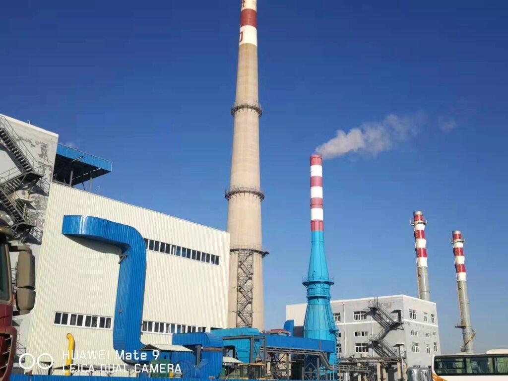
A gas-fired boiler that trips at 2 a.m. on a cold January shift doesn’t just inconvenience the maintenance crew — it halts production, bleeds steam headers, and can cascade into scrapped batches, burst pipes, or frozen process lines depending on what’s downstream. Flame failures alone account for roughly 35% of unplanned shutdowns on gas-fired units; low water level trips add another 20%. Those numbers sound manageable until you price out one eight-hour outage in a continuous-process plant, where lost throughput and emergency service calls can easily run into five figures before the root cause is even identified.
The most effective way to troubleshoot a gas-fired industrial boiler is to work systematically through the four fault categories — combustion/flame, water-side, pressure/safety, and controls — using live sensor readings, flue gas analysis, and historical trip logs rather than guesswork. Most recurring shutdowns trace back to one of three root causes: a drifted sensor, fouled burner components, or inadequate water treatment, all of which are correctable without major parts replacement if caught early.
What makes this harder in practice is that the same symptom — say, a nuisance flame-out — can have four or five completely different origins depending on gas supply pressure, burner turndown position, combustion air damper condition, and even ambient temperature swings in the plant. A boiler running fine at 80% load in summer can start tripping on cold mornings when the gas supply pressure fluctuates and the air-to-fuel ratio drifts just enough to lose flame signal. The sections below work through each fault category the way an experienced service engineer would: starting with what you can measure, not what you can assume.
Flame Failure and Ignition Faults: Diagnosing Burner Lockout Step by Step
Flame failure accounts for roughly 35% of unplanned gas-fired boiler shutdowns — more than low water level, high-pressure trips, and sensor faults combined. Yet in a large share of field cases, the root cause turns out to be something mundane: a fouled UV lens, a mis-gapped electrode, a partially blocked gas filter. The trick is working through the ignition sequence systematically rather than guessing and resetting.
Understanding the Ignition Sequence First
A gas burner doesn’t just “light.” It follows a fixed program — and the controller will lock out at whichever stage fails. Knowing the sequence tells you where to look.
Pre-purge comes first: the fan runs for a set period (typically 15–30 seconds depending on furnace volume) to clear residual gas. The air pressure switch must prove airflow before the controller advances. If it doesn’t, you’ll see a pre-purge lockout before a single spark fires. After pre-purge, the ignition transformer energizes and the pilot gas valve opens. The burner controller expects a flame signal within a tight window — usually 3–5 seconds on most Siemens LMV or Honeywell RM7 series controllers. If the UV/IR scanner doesn’t see a signal, it locks out. Main gas valve opening happens only after pilot flame is confirmed. Missed that sequence? That’s where most field engineers start making wrong assumptions.
Fault 1 — No Spark at All
Check the ignition transformer output first. Output should typically be in the 8–15 kV range; a transformer that reads low or zero on a high-voltage probe is simply failed and needs replacement — they’re not expensive, but lead times can bite you if you don’t keep a spare. Electrode gap is the next item: 3–5 mm is the usual spec, but always verify against the burner manufacturer’s datasheet because some compact burners run tighter. A gap that has closed due to carbon buildup, or opened because someone bumped the electrode, will kill the spark entirely or make it erratic.
Look at the ceramic insulator on the electrode body. Carbon tracking — a dark, conductive deposit running along the surface — will short the spark to ground before it ever jumps the gap. Clean or replace. Also run your hand along the ignition cable looking for any point where the insulation has chafed against the burner body; this is surprisingly common on older Weishaupt and Riello burner installations that have had cables re-routed at some point.
Fault 2 — Spark Present, No Flame
Now you have spark but no ignition. Gas supply is the first suspect. Measure inlet pressure at the burner manifold — for most natural gas low-pressure systems, minimum is somewhere in the 5–20 mbar range, but the exact figure depends on the burner model and nozzle sizing, so pull the datasheet. A pressure reading that’s fine at the meter but low at the manifold usually points to a partially blocked gas filter or a regulator that’s drifting under load.
Check solenoid gas valve operation with a multimeter. Apply rated voltage directly (with due caution) and listen for the click. A valve that hums but doesn’t open fully, or doesn’t respond at all, is a common cause of “spark but no flame” lockouts. Don’t overlook the gas filter — a filter starved of maintenance for a couple of seasons can build up enough debris to cut flow significantly at ignition demand.
Fault 3 — Flame Established, Then Trips
This one frustrates people because the burner actually lights. The UV scanner lens is the leading culprit: combustion deposits, condensation residue, or just accumulated dust on the quartz window can attenuate the flame signal below the relay’s threshold. Wipe the lens with a dry, lint-free cloth — not solvent, which can leave a film. If the signal recovers, you’ve found it.
If the flame is genuinely weak and unstable rather than just misread, check your air-to-gas ratio. O₂ in the flue gas above roughly 5% at full load indicates over-airing. An over-aired flame is lean, lifts off the nozzle, and produces a signal that flickers in and out. A well-tuned burner running optimized combustion should hold CO below 100 mg/Nm³ and NOx below 80 mg/Nm³ — if you’re chasing those numbers during commissioning, excess air is usually where the first tradeoff appears.
UV scanner lens fouling is the leading cause of 'flame established but relay trips' lockouts in gas-fired industrial boilersTrue
Field service data from burner maintenance programs consistently identifies UV/IR scanner signal attenuation due to lens contamination as the primary cause of post-ignition flame relay trips, ahead of actual flame instability.
Fault 4 — Repeated Lockouts After Reset
If the boiler resets and trips again within minutes, stop resetting and start logging. Pull the exact lockout code from the burner controller. On an LMV52 or RM7890, the fault history is stored and accessible — use it. There’s a meaningful difference between a “gas valve proving failure” code and a “flame signal loss after establishment” code; they lead to completely different diagnostic paths. If you’re seeing gas valve proving failures, you need a leak test on the valve train per EN 1643 before you go further. That’s not optional.
A word on safety that shouldn’t need saying, but does: never bypass the flame relay or UV scanner, even temporarily, even “just to test.” These interlocks exist under EN 298 and ASME CSD-1 for a reason. A combustion space with unburned gas and a hot surface is not a controlled experiment.

Combustion Performance Degradation: Fixing Poor Efficiency, Sooting, and High Emissions
Combustion problems are insidious. Unlike a hard lockout that stops the boiler and demands immediate attention, degraded combustion quality can quietly erode thermal efficiency by 3–8 percentage points over weeks, running up fuel bills and edging emissions toward permit violations before anyone notices. By the time the stack is visibly discolored or the quarterly emissions report flags an NOx exceedance, the root cause has often been present for months.
The Triangle of Combustion Quality
Three interdependent variables govern whether a gas-fired boiler burns cleanly and efficiently: air-to-fuel ratio (expressed as excess air percentage), flame shape and stability, and heat release rate relative to furnace volume. Lose control of any one, and the other two drift with it.
Measurement starts with a calibrated flue gas analyzer — a Testo 350, Kane 458, or equivalent — inserted at the correct flue gas sampling port downstream of the last heat transfer surface but upstream of any induced draft fan. You’re looking for O2 in the range of 2–4% at full load on natural gas, CO below 100 mg/Nm³, and NOx below 80 mg/Nm³ for a well-tuned burner. CO2 is a useful cross-check; on natural gas it should sit around 9–10% at optimal excess air. If your analyzer hasn’t been calibrated in the last six months, the readings are decoration.
Black or Yellow Sooty Flame
A sooty or yellow flame on a gas burner is almost always an air-deficiency problem. The usual suspects, roughly in order of frequency: a clogged air inlet filter (common in plants with high ambient dust — textile mills and cement-adjacent sites are notorious for this), a forced-draft fan running below design speed due to worn impeller or belt slip, or an air damper that’s mechanically stuck partially closed. On dual-fuel burners that have been running on light oil at some point, atomizer tip fouling can carry over and affect gas-mode mixing geometry. Premix burners have their own failure mode: partial blockage of the gas/air mixing venturi from debris or, in hard-water areas, mineral scaling on the gas orifice.
Fix sequence: clean or replace the air filter, verify FD fan current draw against the nameplate (a drop of 10–15% usually indicates impeller wear or speed loss), stroke the air damper manually across its full range, and inspect the burner head under good lighting. A warped or scaled burner head distorts the flame envelope more than most engineers expect.
A 1 mm soot deposit on fire-tube heat transfer surfaces increases fuel consumption by approximately 3–5% depending on tube length and flue gas velocity.True
Soot has very low thermal conductivity (roughly 0.1–0.2 W/m·K versus ~50 W/m·K for steel), acting as an insulating layer that forces higher flue gas exit temperatures and reduces heat absorption per unit of fuel fired. This is well-established in boiler heat transfer engineering literature and consistent with field measurements on fire-tube boilers.
That figure is why quarterly combustion analysis and annual tube-side cleaning aren’t optional. The fuel cost penalty compounds fast.
Elevated CO Readings Above 100 mg/Nm³
High CO without visible sooting usually points to incomplete combustion from a different mechanism than simple air starvation. Start by confirming excess air — O2 below 2% at full load means you’re running rich, and CO will spike. If O2 is in range, inspect the burner head for warping or scale buildup that’s disrupting the flame pattern rather than starving it of air. A less obvious cause: refractory damage in the combustion chamber. A cracked or spalled refractory wall creates cold spots and recirculation zones where combustion quenches prematurely. This is easy to miss on a visual inspection if the damage is on the back wall or floor; a thermal camera during a hot inspection interval tells you more.
NOx Exceedances
NOx limits vary considerably — 80 mg/Nm³ is a common threshold in EU installations, while Southeast Asian regulations typically range from 100–150 mg/Nm³ depending on the country and fuel type. Either way, a NOx exceedance is a regulatory event, not just an efficiency problem.
The first thing to check on a low-NOx burner is flue gas recirculation (FGR). If the FGR duct damper has drifted closed — this happens with pneumatic actuators that lose signal or with manual dampers that maintenance staff inadvertently repositioned — thermal NOx formation rises sharply because peak flame temperature is no longer suppressed. Verify the damper position physically, not just from the control panel readout. Check the swirl register settings on the burner head; swirl vanes that have shifted reduce internal flue gas recirculation within the flame itself. On modulating burners, run the unit at 50% and 75% firing rates and compare NOx — if it spikes disproportionately at partial load, the air-to-fuel trim curve needs adjustment for those firing points.
Combustion Tuning Procedure
Do this at four load points: 25%, 50%, 75%, and 100% of rated thermal input. Record O2, CO, CO2, NOx, and flue gas temperature at each point before touching anything. That baseline is your before-state. Then make small incremental adjustments to the air damper position and gas pressure regulator, one variable at a time, allowing the flue gas readings to stabilize for at least 2–3 minutes between adjustments. Document every step. Final trim settings — damper angles, actuator feedback values, gas valve positions — go into the boiler logbook with a date and the technician’s name. In practice, combustion settings drift seasonally; combustion air density changes with ambient temperature, and a burner tuned in January in a northern climate may be running rich by July.
| Symptom | Most Likely Cause | First Check |
|---|---|---|
| Sooty / yellow flame | Air deficiency | Inlet filter condition, FD fan speed |
| CO > 100 mg/Nm³, O2 normal | Burner head or refractory damage | Burner head inspection, thermal camera |
| CO > 100 mg/Nm³, O2 90% of set pressure | Check pressure controller setpoint and bypass valve position | |
| Safety valve chattering repeatedly | Seat damage from repeated partial lifts | Remove, bench-test, and recertify before return to service |
| Pressure rising with reduced firing rate | Burner actuator not following signal | Check gas control valve actuator and feedback linkage |
| Pressure spike after load drop | No burner interlock on process shutdown | Review BMS/DCS integration; add load-tracking interlock |
| Gauge and transmitter readings diverge | Blocked siphon or failed Bourdon tube | Flush siphon; replace gauge if water hammer history exists |
Flue Gas and Heat Transfer Surface Problems: Diagnosing Stack Temperature Rise and Fouling
Stack temperature is one of the most honest signals a boiler gives you. It doesn’t lie, it doesn’t drift the way some pressure sensors do, and if you’ve been logging it consistently at a fixed load point, a creeping rise of 15°C or more above your clean-boiler baseline is telling you something specific — not “there might be an issue somewhere,” but “heat is not transferring where it should.”
Establishing Your Diagnostic Benchmark
On a clean, well-tuned gas-fired boiler, flue gas temperature leaving the economizer outlet should run roughly 20–40°C above the feedwater inlet temperature. The exact spread depends on economizer surface area, feedwater flow rate, and whether you’re running a condensing or non-condensing design. What matters operationally is your baseline — logged at 80–100% MCR with stable fuel composition. Any sustained rise beyond 15°C above that figure, at the same load, is fouling until proven otherwise. A lot of engineers jump straight to combustion tuning when stack temperatures climb. That’s usually the wrong call. Check the heat transfer surfaces first.
Gas-Side Fouling: Acid Deposits and the Dew Point Trap
For natural gas with low sulfur content, the acid dew point sits around 110–130°C. LPG runs a bit higher, and biogas — depending on H₂S content — can push that boundary significantly. When flue gas drops below the dew point anywhere in the gas path, sulfurous condensate forms. You’ll see it as white or pale-yellow powdery scale on economizer fin tubes, around damper housings, or on the casing interior near the stack base.
The boilers most vulnerable to this are modulating units spending long periods at low fire — say, a 6 t/h SZS boiler in a facility with highly variable steam demand, cycling at 25–30% load through a night shift. At low fire, flue gas velocity drops, residence time in the back pass increases, and localized cold spots appear on the tube surfaces. If your process allows it, avoid sustained operation below roughly 40% MCR, or consider fitting a recirculation line to elevate economizer inlet temperature during turndown periods.
Water-Side Scale: The Slow Fuel Thief
Every 1 mm of calcium carbonate scale on boiler tube surfaces increases thermal resistance by approximately 0.5 (m²·K)/kW, leading to a 2–4% rise in fuel consumption.True
This is consistent with established heat transfer engineering data for CaCO₃ deposits on carbon steel tube surfaces. The fuel penalty range depends on scale uniformity, tube geometry, and firing rate.
Scale doesn’t announce itself. It accumulates quietly over months, and the first sign most plants notice is a fuel bill that’s drifted upward without any obvious cause. Water hardness dictates descaling intervals — in practice, if your make-up water runs above 150 mg/L total hardness without effective softening, you’re looking at chemical descaling every 12–18 months at most. Harder water shortens that interval sharply. Keep blowdown records and spot-check tube samples during annual inspection; a 2–3 mm scale layer is not unusual on boilers where feedwater treatment has been inconsistent.
Soot Blower and Mechanical Cleaning: What Actually Works
For SZS water-tube units, retractable soot blowers operating at 0.8–1.0 MPa saturated steam are standard equipment on anything above roughly 10 t/h. Run them on a fixed schedule tied to operating hours, not just when stack temperature triggers an alarm — by the time the alarm fires, you’ve already lost efficiency.
WNS fire-tube boilers are a different situation. There are no soot blowers; the smoke tubes require annual mechanical brushing followed by high-pressure water washing. It’s straightforward work, but it gets skipped. In my experience, plants that skip one annual cleaning on a WNS unit typically see 3–5% efficiency erosion by the following inspection — sometimes more if the burner has been running slightly rich.
Economizer Corrosion: The Row You’re Not Looking At
Inspect the lower rows of economizer fin tubes annually, not just a visual pass from the access door. Pitting corrosion from acid condensation concentrates at the coldest tube surfaces, which are typically the lowest rows on the inlet side. Specifying 09CrCuSb steel — commonly called ND steel — for economizer tubes is worth the modest cost premium in any application where fuel sulfur content is variable or where the boiler will regularly operate at low load. Enamel-coated tubes are another option, particularly for biogas applications with elevated H₂S.
Maintain flue gas temperature at the economizer inlet above 130°C as a working rule. Some designers push this lower to chase condensing efficiency — that’s fine if the system is specifically engineered for it with appropriate materials and a condensate drain, but retrofitting a standard economizer to run below dew point consistently is asking for early tube failure.
Stack Opacity and Bypass Leakage
A sudden drop in CO₂ concentration at constant load, or a visible increase in stack opacity without any change to combustion settings, points to air preheater or economizer bypass leakage before it points to a burner problem. Check expansion joint integrity and damper seals at the back pass. A failed expansion joint will allow cold tramp air to dilute the flue gas stream, drop the measured CO₂, and make combustion instrumentation look like the problem when the actual fault is structural.
This is easy to overlook because the symptoms mimic excess air from a poorly tuned burner. The tell is that adjusting the air-fuel ratio changes nothing, and stack temperature readings become inconsistent across measurement points.
Control System and BMS Faults: Resolving Sensor Failures, PLC Alarms, and Interlock Trips
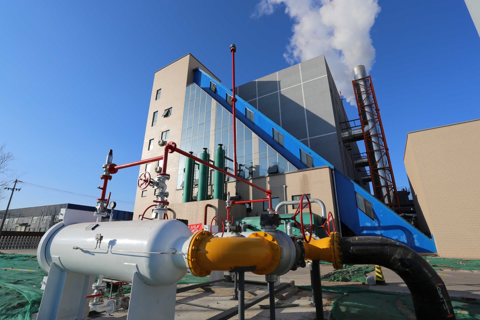
Roughly 18% of unplanned gas-fired boiler shutdowns trace back to control and instrumentation failures — not combustion problems, not water-side issues, just bad signals and miscommunication between layers of hardware that should be talking to each other cleanly. In practice, this category is the most frustrating to diagnose because the boiler itself is often perfectly fine. The fault lives in a 4–20 mA loop, a corroded thermocouple head, or an EMI-ridden fieldbus cable running too close to a VFD panel.
Understanding the Two-Layer Control Architecture
A modern gas-fired industrial boiler runs on two distinct control layers, and keeping them mentally separate is essential when chasing alarms.
The burner management system — typically a dedicated safety controller like a Siemens LMV52, Honeywell FSG, or Fireye NX product — owns the safety interlocks and the ignition sequence. It does not care about load optimization. Its entire job is to confirm safe conditions before allowing a flame, monitor that flame continuously, and trip the burner fast if something looks wrong. It runs on its own internal logic and event log, independent of whatever PLC or DCS sits above it.
The PLC or DCS layer handles modulation, load following, pressure setpoints, feedwater control, and data logging. Faults here tend to produce different alarm signatures — process alarms, communication timeouts, setpoint deviations — rather than the hard lockout codes you get from a BMS trip. Misidentifying which layer threw the fault wastes diagnostic time. Always pull the BMS event log first, then the DCS historian.
Pressure Transmitter Drift
This is more common than most operators acknowledge. Compare the transmitter’s 4–20 mA output — converted to engineering units at the DCS — against the local Bourdon gauge on the same tapping. A deviation greater than roughly 0.5% of calibrated span deserves investigation. Usually it’s one of two things: genuine calibration drift, which accumulates over 12–18 months of thermal cycling, or a partially blocked impulse line, particularly on steam pressure taps where condensate can trap or scale can build up in the root valve area.
Recalibration should be done against a certified dead-weight tester, not another transmitter. Annual recalibration is the floor; quarterly is better on high-cycling boilers.
A pressure transmitter reading deviation of more than 0.5% of calibrated span is sufficient justification for recalibration or impulse line inspection before the next scheduled outage.True
Transmitter drift within this magnitude can cause the BMS or PLC to act on incorrect process values, potentially triggering nuisance trips or — more dangerously — masking an actual overpressure condition. IEC 61511 functional safety guidance and standard instrument maintenance practice both support this threshold.
Thermocouple and RTD Failures
A Type K thermocouple on a gas-fired superheater should track within ±2°C of a reference measurement under stable conditions. Two failure modes cause the most interlock trouble. An open-circuit break — often from vibration fatigue at the thermowell connection or terminal head corrosion — causes the DCS reading to jump instantly to the maximum of the measurement range, which looks exactly like a runaway temperature event to the BMS. A short-circuit to ground does the opposite: the reading collapses toward ambient, and if that thermocouple feeds a low-temperature alarm interlock, you get a nuisance trip on a boiler that’s running normally.
Neither failure should be bypassed to keep the boiler running. Replace the element. A jumpered interlock is a liability.
BMS Nuisance Trips and Event Log Analysis
When operators report a trip but can’t explain what caused it, the BMS event log is the first place to look — not the HMI alarm summary, which often captures the consequence rather than the cause. The LMV52, for example, logs the exact step in the start sequence where the fault occurred, the fault code, and the time. That alone narrows the diagnostic space considerably.
The distinction that matters most: was this a true safety condition, or a sensor failure that produced a false signal? A gas valve position feedback mismatch — where the valve is commanded open but the end-switch confirms closed — is a legitimate safety trip. But if the same fault code appears repeatedly and the valve checks out mechanically, the feedback switch itself is the problem. Replacing the switch is the fix. Resetting and re-running is not.
PLC Communication Faults and EMI
In boiler rooms with variable-frequency drives on FD fans and feedwater pumps — which is most modern installations — electromagnetic interference is a real and underappreciated problem. Modbus RTU and PROFIBUS DP are both susceptible to noise-induced errors that manifest as random, non-reproducible interlock trips. The pattern is usually intermittent: the boiler runs fine for days, then trips twice in one shift, then runs fine again.
Corrective steps are straightforward but often skipped during commissioning: shielded twisted-pair cable for all fieldbus runs, with shield grounded at one end only; physical separation of signal cables from VFD output power cables by at least 200–300 mm; ferrite core EMI filters on VFD output cables near the drive. Grounding quality in the MCC room deserves a look too — a poor ground bus connection in a humid climate can cause leakage currents that corrupt signal integrity over time.
Remote Monitoring on EPC Projects
For boilers commissioned on EPC projects in Southeast Asia, the Middle East, or sub-Saharan Africa, on-site diagnostic support is expensive and slow. Taishan Group packages intended for those markets are configured with OPC-UA or MQTT-based remote monitoring that gives the engineering team access to real-time process data, alarm histories, and BMS event logs without dispatching a technician. In field experience across multiple projects, this reduces mean time to diagnose by roughly 60% — the difference between a same-day resolution over a remote session and a 48–72 hour wait for someone to arrive on site. It also builds a maintenance history that makes the next fault faster to solve.
Preventive Maintenance Schedule: What to Inspect Daily, Monthly, and Annually on Gas-Fired Boilers
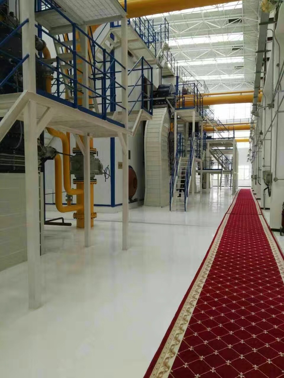
A surprising amount of boiler downtime is traceable not to equipment failure but to inspection intervals that were either too long or never defined in the first place. Get the schedule right and you’ll catch roughly 60–70% of developing faults before they become trips or tube failures. Miss it, and you’re troubleshooting under pressure — sometimes literally.
Daily Checks: The 15–20 Minute Operator Round
This is non-negotiable. Every shift, every day. The operator walks the boiler with a paper or tablet log and records operating pressure, steam or hot water outlet temperature, feedwater flow rate, flue gas stack temperature, and burner firing rate. These five numbers are your baseline. A stack temperature creeping up 8–12°C over two weeks without a load change is fouling, not a combustion fault — that distinction matters because the fix is completely different.
Visually inspect the water gauge glass for clarity and correct level position. A glass that’s slow to recover after a blowdown test is telling you the connection is partially blocked — don’t ignore that. Check gas supply pressure at the meter and at the burner manifold; a pressure drop between the two points that exceeds roughly 5–10 mbar more than usual suggests a regulator issue or downstream obstruction. And yes, physically test the safety valve lift levers — briefly, just enough to confirm they’re not seized. In climates with cold winters, seized levers are common after seasonal startup.
Weekly Checks
Blow down the low-water cutoff floats and gauge glass columns. This takes about ten minutes and prevents the single most dangerous failure mode in steam boiler operation. Test the manual emergency stop from the panel and confirm the BMS responds correctly.
Inspect the burner air filter. A pressure drop across the filter above roughly 15 mbar means it needs replacement, not cleaning — trying to wash a loaded industrial burner filter usually damages the media. Check condensate return temperature and quantity against your normal baseline. A sudden 20% drop in condensate return volume usually means a steam trap has failed open, which wastes heat and inflates your water treatment costs almost immediately.
Monthly Checks
Run a full combustion analysis with a calibrated flue gas analyzer — not the boiler’s built-in O₂ sensor alone, which drifts. You’re looking for CO below 100 mg/Nm³ and NOx below 80 mg/Nm³ under normal load. Values outside these ranges warrant burner adjustment before the next regulatory inspection, not after.
Pull and inspect the burner head and ignition electrodes. Electrode gap erosion of more than about 1–1.5 mm from spec is enough to cause intermittent ignition faults. Clean the UV scanner lens; a thin film of combustion deposit reduces flame signal strength and eventually causes nuisance lockouts that maintenance teams often misattribute to the scanner itself when the lens is the real culprit.
Perform a controlled blowdown to bring boiler water TDS back within specification — the acceptable range depends on your water treatment program and operating pressure, typically 1,500–3,500 ppm for shell boilers below 10 bar, but always confirm against your water treatment supplier’s guidance.
Quarterly Checks
Inspect the economizer and air preheater for fouling using the stack temperature trend you’ve been logging daily. Test all safety valves by manual lift and document the results. Run vibration analysis on FD fan bearings — a bearing showing early-stage defect frequencies can usually run another quarter if monitored weekly; one already in the fault zone cannot.
Calibrate all pressure and temperature transmitters against a reference standard. Sensor drift of 2–4% sounds small but can shift burner modulation behavior enough to affect efficiency by a measurable margin. Review the BMS event log for recurring alarm patterns; if the same alarm fires three or more times in a quarter without a root-cause correction, the cause hasn’t been fixed — it’s been reset.
Annual Overhaul
Internal inspection of the boiler drum and tubes requires a certified inspector in most jurisdictions — this is a statutory requirement, not optional. Plan for 3–5 days of outage depending on vessel size and access configuration. If local regulations or insurance terms require a hydraulic pressure test, it’s typically conducted at 1.25–1.5× design pressure; confirm the exact multiplier with your inspection authority.
Replace the burner refractory quarl if there’s visible erosion or cracking. A degraded quarl destabilizes the flame shape and pushes combustion farther into the furnace, raising tube metal temperatures in the wrong places. Overhaul feedwater pump mechanical seals and impeller wear rings — seal failure is the most common pump fault and, in my experience, almost always shows up just after annual inspection when pumps are reassembled carelessly.
Conduct a full NOx and CO stack emissions test for permit compliance, ideally under representative load conditions rather than at low fire, which can produce artificially clean results.
Documentation and Handover
Keep a boiler logbook — paper or digital — covering every reading, fault event, maintenance action, and part replacement with dates and technician identification. This record is required by most insurance underwriters and statutory inspection bodies, and it’s the only reliable performance baseline you’ll have when diagnosing a problem eighteen months from now.
Maintaining a consistent boiler logbook with daily readings and fault events significantly reduces diagnostic time during unplanned shutdowns.True
Root-cause diagnosis depends on trend data. Without baseline readings for stack temperature, pressure, and combustion parameters, engineers are working blind — diagnostic time increases substantially and misdiagnosis risk rises.
For EPC projects, Taishan Group provides digital O&M manuals and structured maintenance log templates as part of the project handover package, pre-configured for the specific boiler model, capacity, and fuel type supplied — which means the operator isn’t starting from a blank spreadsheet on commissioning day.
Frequently Asked Questions About Industrial Gas-Fired Boiler Troubleshooting
Why does my boiler keep locking out on flame failure even after I clean the UV scanner?
Cleaning the scanner is always the right first step, but if lockouts continue, you’re looking at one of three more stubborn causes. First, check gas supply pressure at the burner train inlet during the proving period — not just at the meter. Gas pressure that sags below the burner’s minimum inlet requirement during the proving sequence (often 5–30 mbar depending on burner model) will prevent stable ignition even with a perfectly clean scanner. Pressure fluctuations are worse during morning demand peaks or when multiple appliances share a header.
Second, a leaking gas valve — even one that passes its standard seat leak test at low differential — can allow enough gas to accumulate in the combustion chamber during pre-purge that the mixture is too rich to ignite on the first spark. The burner fires nothing, the UV scanner sees nothing, and the BMS locks out. You’ll sometimes smell gas briefly at the flue during this sequence.
Third, inspect the ignition electrode ceramic for hairline cracks. A cracked ceramic lets the spark track to the electrode body or burner head rather than jumping the gap properly. The spark sounds normal, the ignition transformer checks out fine, but there’s no reliable arc at the tip. Replace the full electrode assembly — not just the tip — and retest.
What should I do if my boiler trips on low water level but the gauge glass shows normal?
Do not restart the boiler and assume the safety device is faulty. That logic gets tubes damaged. This scenario is almost always a false trip caused by scale, grease, or mineral deposits coating the low-water cutoff probe or float chamber, which disrupts conductivity or buoyancy. Blow down the gauge glass and the cutoff device per the manufacturer’s blowdown procedure, then observe whether the cutoff device resets correctly. If the gauge glass shows normal but the cutoff continues to trip after blowdown, the probe requires cleaning or replacement. Physically verify both independently before drawing any conclusion about which one is correct.
How often should combustion be tuned on a modulating gas-fired boiler?
A full tune — meaning O₂, CO, and NOx checked across at least three firing rates — is required at commissioning, after any burner component replacement, and at each annual service. Beyond the calendar schedule, tune whenever fuel supply conditions change. A shift in gas calorific value or Wobbe index greater than roughly 5% is enough to push CO or NOx outside acceptable limits and measurably erode efficiency. Seasonal gas quality variation is real in some supply networks and is underappreciated as a tuning trigger.
My boiler efficiency has dropped about 4% over six months with no alarms. Where do I start?
A slow, alarm-free efficiency loss is almost always fouling — on one side of the heat transfer surface or both. Start with flue gas exit temperature. If it has risen more than around 15°C above your clean-boiler baseline at equivalent load, fouling is confirmed. Then test boiler water TDS and hardness to determine whether you’re dealing primarily with gas-side soot/sulfate deposits or water-side scale. Both can coexist, and treating only one will leave efficiency partially recovered. Re-benchmark only after both are addressed and the boiler has stabilized over several operating days.
Can I use the same diagnostic approach for a thermal oil heater as for a steam boiler?
No, and conflating the two is a genuinely dangerous mistake. Thermal oil heaters operate at film temperatures up to 320°C for mineral oil and up to roughly 400°C for synthetic fluids — the failure modes are completely different. Scale and corrosion fade as primary concerns; oil degradation, coking on tube surfaces, and vapor lock move to the front. Diagnostic priority shifts to oil quality analysis (viscosity, flash point, acid number trending), tube skin temperature monitoring at multiple points, and expansion tank level and pressure behavior. A steam boiler checklist applied to a thermal oil heater will miss the most dangerous faults entirely.
Thermal oil heater diagnostics require oil quality analysis (viscosity, flash point, acid number) as a primary tool, not the water chemistry checks used for steam boilers.True
Thermal oil systems degrade through oxidation, thermal cracking, and contamination rather than scale-forming mineral deposits; oil analysis is the recognized primary diagnostic method per EN 12828 guidance and major heat transfer fluid manufacturer service protocols.
Steam is being generated but pressure won’t reach setpoint — what do I check?
Three causes cover most of these cases. First, verify that actual steam demand matches the boiler’s rated output — a capacity mismatch is more common than it sounds, especially after process expansion. Second, confirm the burner is actually reaching full firing rate: check gas inlet pressure, air damper position, and VFD speed on the forced-draft fan simultaneously. A gas pressure dip, a stiff damper linkage, or a VFD limited by a parameter someone changed will all cap firing rate invisibly. Third, conduct a system pressure decay test with all process valves closed to rule out a steam or condensate leak consuming output faster than the boiler produces it.
How does remote diagnostics work for overseas EPC projects?
For projects supplied with Taishan Group industrial boilers, the standard EPC package includes an onboard PLC pre-configured with redundant pressure, temperature, and flow transmitters and data export via OPC-UA or MQTT. This allows the technical support team to review real-time and historical trending data remotely, correlate fault sequences, and issue corrective guidance without waiting for a site visit. For customers in Southeast Asia, the Middle East, and Sub-Saharan Africa — where qualified boiler specialists may be hours away — this capability routinely compresses fault diagnosis from days to hours. It also generates the historical dataset needed to distinguish a one-off trip from a developing mechanical trend, which is something no amount of on-site visual inspection replaces.
References
BPVC Section VII — Recommended Guidelines for the Care of Power Boilers — ASME
BPVC Section VI — Recommended Rules for the Care and Operation of Heating Boilers — ASME
Boiler Logs Can Reduce Accidents — National Board of Boiler and Pressure Vessel Inspectors
Boiler Efficiency and Combustion — Spirax Sarco
Water for the Boiler — Spirax Sarco
Boiler Fittings and Mountings — Spirax Sarco
Boilers and Fired Pressure Equipment — Inspection, Repairs and Alterations — ASME
How to Troubleshoot Common Issues in Industrial Gas-Fired Boilers? Read More »