
What Are the Best Practices for Routine Maintenance of Circulating Fluidized Bed Boilers?
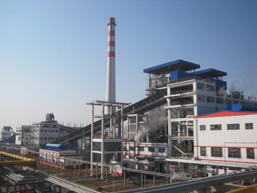
Unplanned shutdowns on a CFB boiler don’t announce themselves — they build quietly through ignored refractory cracks, a few too many clogged air distributor nozzles, or bed material that’s gone fine-heavy and started channeling instead of fluidizing. By the time the forced outage hits, you’re looking at emergency refractory patch work under pressure, expedited parts freight, and lost steam production that cascades into process downtime worth multiples of whatever the maintenance budget would have cost. Plants running without a structured maintenance program routinely see forced outage rates of 6–10% annually; well-maintained units can hold that below 2%. The gap is almost entirely discipline, not hardware.
CFB boiler routine maintenance best practices include scheduled refractory inspection every 4,000–8,000 operating hours, ultrasonic thickness testing of superheater tubes at roughly 8,000-hour intervals, bed material particle-size monitoring with replacement triggered when fines exceed 30% of the sample, air distributor nozzle audits capped at 5% blockage before a full grid inspection, and a major overhaul every 18–24 months — each interval adjusted for fuel quality, load cycling frequency, and actual operating temperature relative to the 850–950 °C design window.
What separates operators who consistently hit long service intervals from those who are always firefighting isn’t exotic technology or a bigger maintenance crew. It’s knowing exactly which failure modes are slow and measurable versus which ones are fast and brutal — and building inspection cadences around that distinction. The sections below work through each major system in the order a plant engineer would actually encounter them on a walkdown.
Daily and Weekly Inspection Routines: Shift-Level Tasks Every CFB Operator Must Execute
Most CFB reliability problems don’t announce themselves — they accumulate quietly across dozens of shifts while operators record numbers without really reading them. A disciplined shift routine catches the drift before it becomes a forced outage.
Bed Temperature Profiling: Your First Combustion Signal
Every shift, operators should be reading the full thermocouple array across the furnace cross-section, not just the average displayed on the DCS screen. The target window is 850–950 °C, and that range isn’t arbitrary — below 850 °C, combustion efficiency falls off and carbon carryover climbs; above 950 °C, refractory wear accelerates measurably and agglomeration risk increases. What you’re hunting for is deviation: any single point reading more than 30 °C above or below neighboring points in the same horizontal plane.
That kind of hot-spot deviation usually means one of three things — uneven fuel feed (a stuck spreader nozzle, a bridging problem in the feed chute), air maldistribution from a partially blocked distributor nozzle, or localized bed defluidization from particle size drift. Any of those left unaddressed for a full shift can cause a cold leg and the chain of problems that follows. Don’t wait for end-of-shift summary; check the thermocouple spread at least twice per shift during normal load, more frequently during load changes or fuel quality transitions.
Pressure Drop Readings Across the Furnace Loop
Differential pressure across the bed, the cyclone inlet-outlet, and the loop seal tells you more about boiler health than almost any other single measurement. A mid-size industrial CFB running 35–80 t/h steam will typically show a furnace bed pressure drop somewhere in the range of 5–10 kPa, depending on design inventory and fluidizing velocity — your specific design baseline is what matters, not a generic figure.
A steadily rising ΔP often means bed inventory is building, possibly from insufficient ash drainage or a partially closed bed drain valve. A falling ΔP is more dangerous: it usually signals inventory loss — either a drain valve stuck open, or refractory spall from the furnace walls entering the circulating loop and grinding down the solids. Cyclone ΔP trending downward over several shifts can also indicate internal erosion thinning the gas flow path. Log the actual numbers, not just “normal/abnormal.” Trend lines over a week tell you things a single reading never will.
Flue Gas Composition: Catch Combustion Drift Early
At the economizer outlet, operators should be logging CO, O₂, SO₂, and NOx every shift — minimum. CO above roughly 100–200 ppm (depending on permit limits and fuel type) usually indicates incomplete combustion, often linked to either poor fuel distribution or bed temperature dropping toward the lower end of the window. Elevated O₂ with high CO simultaneously points to channeling or poor mixing rather than a simple air-starved condition.
SO₂ trending upward while limestone feed rate holds steady? Either the Ca/S molar ratio has slipped below the 1.8–2.5 range needed for 80–90% in-furnace capture, or the limestone particle sizing is off. Both are correctable quickly if caught early. Ignored for weeks, they become an emissions violation with regulatory consequences.
Monitoring flue gas CO and O₂ trends at shift frequency can prevent combustion drift from escalating into an emissions permit breach or avoidable refractory damage.True
CO and O₂ are direct indicators of combustion quality and air-fuel balance; daily trend logging is a documented practice in CFB operational standards from major OEMs and reflected in plant commissioning handover protocols.
Weekly Walkdowns: Eyes, Ears, and an Infrared Thermometer
Once per week, someone with actual CFB experience — not just the newest shift hand — needs to physically walk the boiler. Listen to the ID fan and PA fan bearings. An emerging bearing problem often announces itself as a subtle change in tone before vibration sensors alarm; experienced operators learn to recognize it. Check every expansion joint on the flue gas ductwork for cracking or displacement, especially in the first 1–2 meters off the furnace outlet where thermal cycling is most severe.
Carry an infrared thermometer and scan the external casing panels systematically. A hot spot on the casing surface — say, 20–40 °C above the surrounding panels — can indicate refractory delamination or a burned-out anchor. Find it weekly and you’re looking at a targeted patch repair during the next planned outage. Miss it for three months and you may be looking at an unplanned emergency shutdown and a much larger refractory rework scope.
Ash cooler discharge temperature is worth a dedicated check. If it’s running higher than design (typically 150–200 °C at the cooler outlet, depending on unit design), that’s either reduced cooling airflow or a cooling surface fouling problem. Neither is serious in isolation, but both waste energy and the latter will worsen progressively.
Soot Blower and Bed Drain Verification
Automated soot blower sequences are easy to ignore precisely because they’re automated — until a sequence starts failing silently and the convection pass starts plugging. Once per shift, verify the DCS completion log actually shows the full sequence ran. A blower that fires but doesn’t travel its full stroke, or one that’s been isolated because of a steam leak and never put back in service, can foul the superheater or economizer surface in a matter of days under high-ash fuel conditions.
Bed drain valves need a manual cycling check weekly at minimum. Target bed inventory for a mid-size unit (roughly 35–130 t/h output range) is typically 15–25 tonnes, and maintaining that inventory window is fundamental to stable fluidization. Drain valves that stick — either open or closed — are common, particularly on units running high-silica fuels that leave abrasive ash residue on valve seats.
Shift Log Discipline
A shift log that gets filled out but never read is just paperwork. The standard Taishan Group recommends during EPC commissioning handover is standardized electronic fields for each critical parameter, with hard limits defined in the system — any reading outside the control band generates an automatic flag that must be acknowledged and commented on before the shift closes. That discipline forces the conversation between the outgoing operator and the maintenance supervisor while there’s still time to act on it. Without that structure, problems that should have been caught on Tuesday get discovered on Friday when they’ve become something worse.
Monthly and Quarterly Maintenance Tasks: Mechanical Integrity and Wear Monitoring
The daily rounds catch acute problems. Major overhauls address accumulated damage. The monthly and quarterly window is where progressive wear — the slow erosion of nozzle throats, the creeping thinning of a cyclone cone wall, the gradual drift of fan alignment — either gets caught or quietly compounds into a forced outage that nobody saw coming until it was too late.
Air Distributor Nozzle Inspection
Every 30 days, pull a representative sample — at minimum 5% of the total nozzle count, accessed through inspection ports or cleanout hatches — and examine them closely. You’re looking for three distinct failure modes that often coexist: erosion at the orifice throat (the discharge diameter grows, fluidizing air velocity drops, and bed channeling follows), internal bridging from coke or fine ash that has back-migrated and hardened, and cracks at the weld root where the nozzle joins the distributor plate. Any one of these, in sufficient numbers, kills uniform fluidization.
The threshold that triggers full-grid replacement is firm: if more than 5% of the total nozzle population is confirmed blocked or structurally compromised, a complete grid inspection and replacement is mandatory. That number isn’t conservative caution — it’s derived from fluidization mechanics. Even a 5% blockage creates localized defluidization zones that concentrate bed temperature, accelerating refractory and evaporator tube wear simultaneously.
Cyclone Separator Wall Thickness Measurement
Quarterly ultrasonic thickness gauging on the cyclone barrel and cone sections is non-negotiable on any CFB running abrasive fuels — which is most of them. Use a calibrated UT gauge on a grid pattern: typically 50–100 mm spacing in the high-wear cone transition zone, wider in the barrel. Record every reading against the original fabrication certificate. The actionable threshold is a wall thickness reduction exceeding 20% of the original nominal spec. At that point, you’re not just managing wear; you’re managing risk of a breach under operating pressure and temperature.
Ceramic tile lining upgrade kits for cyclone high-wear zones — the type Taishan Group supplies for retrofit applications — can extend service intervals significantly in situations where the original bare steel or castable refractory is wearing faster than the design predicted, often because actual fuel ash characteristics differ from the specification case.
Loop Seal Aeration and Refractory Check
The loop seal is one of those components that gets ignored until it fails, which is unfortunate because a seized loop seal will drop bed inventory and destabilize combustion within minutes. During planned short outages — even a 12-hour maintenance window — use a borescope to inspect the standpipe and loop seal refractory for cracking, spalling, or joint separation. Verify that all aeration taps are delivering flow at design rates; a blocked aeration nozzle here is harder to detect in operation than a distributor nozzle, but the consequence is similar. If the refractory in the loop seal shows cracking beyond surface crazing, it needs patching before the next extended run.
Fan Bearings, Alignment, and Vibration Baseline
The ID fan, primary air fan, and secondary air fan collectively represent the largest rotating machinery exposure on the unit. Monthly, check vibration against your documented baseline — the working target for this class of machine under ISO 10816 is below 4.5 mm/s RMS, though the actual alarm and trip setpoints depend on bearing type, shaft speed, and OEM guidance. Re-grease or top up oil-bath housings strictly per OEM intervals; over-greasing is as damaging as under-greasing. Check coupling or belt alignment every quarter. Thermal growth between cold-alignment and operating temperature can shift alignment by 0.1–0.3 mm depending on baseplate design and ambient temperature swings — more pronounced in plants with significant seasonal variation.
Fan misalignment is a leading cause of premature bearing failure in CFB boiler auxiliariesTrue
Misalignment induces cyclic bending loads on bearing races that significantly exceed design loads, accelerating fatigue failure; this is well-documented in rotating equipment reliability studies and consistent with field experience on CFB auxiliary systems.
Safety Valve Functional Testing
On low-pressure steam or hot-water units, a monthly lift test verifies the valve hasn’t seized from corrosion or mineral deposits. For high-pressure steam boilers — anything above 3.82 MPa — most national boiler codes require a full-lift verification quarterly, with documented third-party witness. Don’t skip the documentation. An undocumented test is legally equivalent to no test in most jurisdictions, and insurers treat it the same way.
Water and Steam Quality Quarterly Sampling
Scale is deceptively cheap to prevent and expensive to remedy. A hardness, pH, conductivity, dissolved oxygen, and silica analysis every quarter gives you the data to adjust chemical dosing before a problem develops.
A 0.3 mm hard scale deposit on evaporator tubes reduces heat transfer efficiency by 7–10%True
Scale acts as a thermal insulator; the conductivity of calcium carbonate/sulfate scale (roughly 0.5–3 W/m·K) is orders of magnitude lower than steel (roughly 50 W/m·K), and even thin deposits measurably increase tube wall temperature, reducing efficiency and accelerating creep and overheating failures.
Silica deserves particular attention in high-pressure units — silica carryover into superheater steam causes deposits that are extremely difficult to remove without mechanical intervention. Getting ahead of it quarterly costs almost nothing. Fixing a silica-fouled superheater mid-campaign costs days of outage.
Annual Major Overhaul Planning: Scope Definition, Shutdown Sequencing, and Critical Path Items
A major overhaul is not something you plan two weeks before the shutdown window. On a 75 t/h CFB unit running 18–24 months between major outages, the planning cycle should start at least four to six months out — and it begins not with a contractor call, but with your own inspection database.
Building the Scope from Real Data, Not Habit
Pull everything: ultrasonic thickness logs from the last 8,000-hour superheater UT campaign, nozzle sample results from quarterly pulls, bearing vibration trend charts from the induced-draft and primary-air fans, and water chemistry records that might hint at internal corrosion you haven’t seen yet. Run each component through a simple three-column risk matrix — Replace Now, Monitor Through Next Cycle, or Defer — weighted by remaining wall thickness relative to the 80% nominal retirement threshold, deviation from original vibration baseline, and how close any measurement is to a known failure boundary (that 20% cyclone wall thickness reduction figure, for instance, is not a suggestion).
In practice, plants that skip this step and write scope from memory end up either over-spending on components that had years left, or — more dangerously — missing a superheater pendant that was already down to 78% wall thickness and failing catastrophically six months after restart. The database-driven approach isn’t bureaucracy; it’s the only way to make a defensible Replace Now call.
Critical Path Sequencing for a 10–14 Day Outage
Day 1–2 is cooldown and full lockout/tagout. Rushing this is tempting when the shutdown window is tight — don’t. Residual heat in the refractory mass of a CFB furnace is substantial, and workers entering a furnace that hasn’t reached safe entry temperature is one of the more common serious injuries in boiler maintenance. Verify bed temperature at multiple elevations before any personnel entry.
Days 2–4 go to refractory demolition and inspection. This is also when you get your first real look at nozzle grid condition, cyclone barrel wear, and loop seal tile integrity — things you can’t fully assess from outside. Mark and photograph every area of refractory spalling, cracking, or delamination before demolition removes the evidence.
The heaviest work runs Days 4–8: refractory repair and replacement, tube inspection program (100% visual of all accessible tubes, UT on a minimum 10% stratified sample weighted toward high-velocity zones near the furnace nose and cyclone inlet), and nozzle grid work. If any tube shows wall loss exceeding 15% of nominal on UT, pull a metallurgical sample — you need to know whether it’s erosion, corrosion, or a combination before you decide on a tube replacement strategy or material upgrade.
Mechanical reassembly and new bed material loading follow on Days 8–11. Bed material particle size matters here: silica sand in the 0.1–0.3 mm mean diameter range, with the fines fraction checked before loading. Starting a unit with out-of-spec bed material loaded during overhaul is an embarrassing and avoidable way to generate your first forced outage of the new cycle.
Days 11–14 are for refractory cure, cold air flow test across the nozzle grid (confirming no blockages before any combustion), and recommission sequence.
Refractory Material Selection — Where Most Field Failures Begin
Dense castable refractory (typically 2,200–2,600 kg/m³) belongs on the furnace floor and lower walls where abrasion loading is highest. Plastic refractory is the right choice around nozzle throats and irregular penetrations where casting is impractical. Ceramic fiber blanket is appropriate for the upper furnace and cyclone barrel insulation where temperatures are lower and you need compliance, not density. Using castable where fiber blanket was specified — or vice versa — is the single most common cause of premature refractory failure I’ve seen in CFB units after overhaul. It usually shows up as cracking within the first 500 hours of operation.
Spare Parts Pre-Positioning
Procurement delays are the primary reason overhauls run over schedule. Maintain a minimum strategic stock before the outage begins: one complete nozzle grid set, two sets of loop seal refractory tiles, one full cyclone lining kit, critical fan bearings for both ID and PA fans, and one boiler feed pump cartridge. That list looks expensive sitting on a shelf, but a single extra day of unplanned outage on a 75 t/h unit supplying process steam typically costs more than the holding cost of that entire stock.
Staged refractory bake-out at controlled heat-up rates is required to prevent steam-spalling cracking in new castable refractory installations.True
New castable refractory contains residual moisture from installation. Rapid heat-up converts this moisture to steam faster than it can escape, generating internal pressure that causes cracking or spalling. A controlled ramp — typically 20–30 °C/hour to a 110 °C hold, then stepped increases of roughly 50 °C/hour — allows moisture to migrate out gradually before sintering begins.
The bake-out curve is non-negotiable. A correctly staged ramp — 20–30 °C/hour up to a 110 °C soak, then roughly 50 °C/hour in steps to operating temperature — is the difference between refractory that lasts 18 months and refractory that spalls on the second week of operation. Taishan Group supplies site-specific bake-out curves with every new refractory package, calibrated to the actual material thickness, ambient humidity conditions, and unit geometry — because a generic curve copied from a handbook won’t account for a 380 mm floor casting in a humid coastal climate the same way it handles a 120 mm wall panel in an arid inland site.
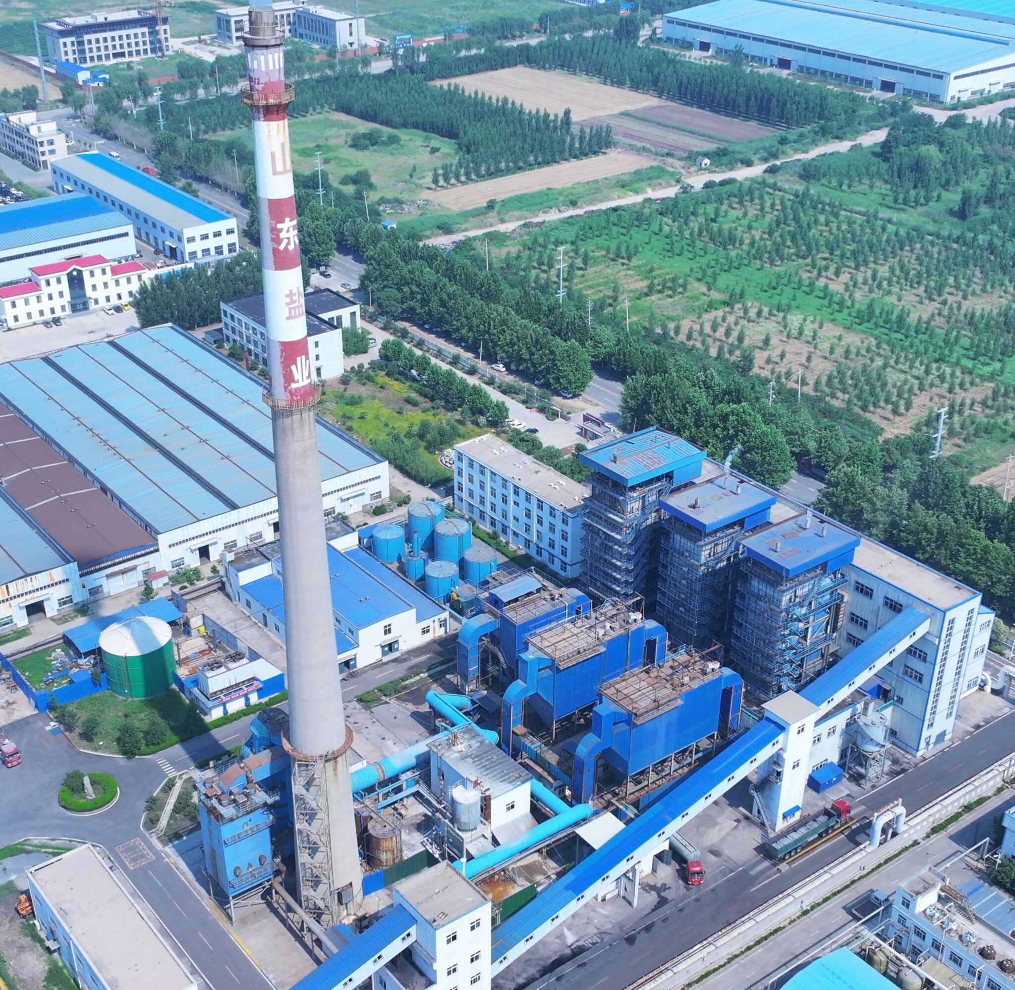
Refractory and Wear-Part Management: The Single Largest Maintenance Cost Driver in CFB Boilers
No other industrial boiler technology punishes its refractory lining the way a CFB does. A conventional pulverized-coal furnace is mostly a radiant heat problem. A CFB is that, plus a sandblasting machine running continuously at particle velocities of 5–15 m/s, plus cyclic thermal swings every time load shifts or the unit trips, plus chemical attack from alkali sulfates and — if you’re firing biomass or refuse-derived fuel — chloride compounds that infiltrate castable binders and accelerate spalling from the inside out. That triple threat is what makes refractory the dominant line item in CFB lifecycle cost, often running 30–45% of total maintenance spend depending on fuel type and plant operating schedule.
Why the Damage Mechanisms Stack on Each Other
Thermal cycling alone would be manageable. Mechanical erosion alone would be manageable. The problem is that erosion strips away the hardened surface layer of the castable, exposing fresh material to chemical penetration, which weakens the matrix, which makes it more susceptible to the next thermal shock. Each mechanism accelerates the others. In practice, plants burning high-ash coal (ash content above 25%) or mixed biomass with significant chlorine content — agricultural residues, municipal solid waste fractions — should expect lining degradation rates roughly 1.5–2× faster than a plant on clean bituminous coal at similar thermal output.
The Five Zones That Deserve Disproportionate Attention
Maintenance resources are finite, and spreading inspection effort uniformly across a CFB furnace is a mistake. The real wear concentrates predictably:
Lower furnace splash zone (0–3 m above the air distributor) — circulating solids hit the walls at the highest density here. Castable thickness loss of 8–15 mm per year is common in high-ash applications.
Furnace-to-cyclone transition duct — the geometry forces gas and solids to accelerate and change direction. Both erosion and thermal gradient cracking concentrate at the duct corners.
Cyclone cone — the spiraling solids track along the cone wall continuously. This is the zone where I’ve seen 20 mm of original castable reduced to 6–7 mm inside a single 8,000-hour campaign on high-silica coal ash.
Loop seal standpipe lower section — frequently neglected because it’s out of the main visual inspection path. Fluidization air creates localized turbulence that scours the inner radius of the standpipe bend.
Ash cooler inlet — hot ash entering at 750–850 °C impinges directly on the inlet geometry. Plants that run continuous ash extraction operate this zone near its thermal design limit constantly.
Inspection interval for refractory should be every 4,000–8,000 operating hours, or annually — whichever arrives first. If you’re consistently hitting wear limits at 4,000 hours in the splash zone, that’s a material upgrade signal, not just a scheduling problem.
Material Upgrade Pathways That Actually Pay Off
Standard dense castable in the 45–55% Al₂O₃ range is adequate for moderate-duty applications. In the peak erosion zones above, it usually isn’t. Transitioning to high-alumina castable at 65–75% Al₂O₃ in the splash zone and cyclone cone typically extends relining intervals from around 18 months to 36–48 months — the exact gain depends on fuel ash abrasiveness, operating temperature, and how well the material is installed (curing schedule matters enormously; rushed ambient curing is a common installation error that kills the density of even premium castable).
Silicon carbide-bonded castable is worth the cost premium in the furnace-to-cyclone duct and cyclone cone inlet, where erosion rates are highest and installation access is worst. In installations processing high-silica coal ash, 92–99% alumina ceramic hexagonal tiles adhesive-bonded over existing castable lining in cyclone barrels have demonstrated roughly 3× erosion life compared to castable alone. The tile overlay approach also allows partial repair — damaged tiles can be replaced without stripping the full lining system, which cuts outage time significantly on unplanned repairs.
Upgrading splash-zone castable from standard 45–55% Al₂O₃ to 65–75% Al₂O₃ formulations can extend relining intervals from roughly 18 months to 36–48 months in high-ash fuel applications.True
This is consistent with published wear data from refractories suppliers and documented plant experience; actual interval depends on fuel ash abrasiveness, particle size distribution, and operating temperature within the 850–950 °C CFB window.
Anchor System: The Part That Fails Silently
The castable doesn’t fall out on its own — it falls out when the anchors fail. V-anchors and Y-anchors in the lower furnace operate in a partially reducing atmosphere at temperatures that accelerate oxidation scaling and, in chlorine-rich fuel environments, active corrosion through chloride attack on the anchor welds. Minimum anchor density in the splash zone is 36 anchors/m² by established industry practice; I’ve seen plants running 22–24/m² in poorly designed original installations, and they wonder why lining panels keep dropping. During every major overhaul, every anchor in the wear zones should be tapped for looseness, visually inspected for neck corrosion, and replaced if cross-section is reduced more than roughly 20% from original.
Keeping a Refractory Health Map
Without systematic documentation, each outage essentially starts from scratch. A refractory health map — a CAD drawing of the furnace interior with each panel’s last measured thickness, material specification, installation date, and next predicted inspection date — turns empirical data into a defensible maintenance budget. Taishan Group includes a digital as-built refractory map with all CFB units supplied under EPC contracts, so the plant owner starts operations with a baseline rather than guessing. After that, the plant’s own maintenance team should update the map after every inspection. It’s not glamorous work, but it’s the difference between budgeting a planned reline and being surprised by a furnace wall failure at 2 a.m. on a production weekend.
Air Distribution System Maintenance: Nozzle Grids, Wind Boxes, and Fluidization Quality Control
The air distribution system is one of those subsystems that experienced CFB engineers watch closely and newer operators tend to ignore — right up until a bed agglomeration event forces a two-week unplanned shutdown. The distributor plate and its nozzles do something deceptively simple: they take primary air from the wind box and introduce it into the bed in a way that keeps every cubic centimeter of bed material in uniform suspension. When that uniformity breaks down, everything downstream suffers.
How a Single Clogged Nozzle Starts a Cascade
Each bubble-cap or directional nozzle governs a small territory of bed area. Clog one — or let it erode to the point it loses directional control — and you create a dead zone. Bed material in that zone defluidizes and settles. Local temperatures climb because combustion continues but heat transfer to the now-static material drops sharply. Depending on fuel ash characteristics and furnace temperature, agglomeration can begin within a few hours of that zone going cold. By the time operators see an abnormal bed pressure drop or a temperature spike on a thermocouple, the condition is already well advanced.
The standard tolerance is no more than 5% of nozzles clogged before a full grid inspection is mandated. In practice on a 65 t/h coal-fired CFB, that translates to perhaps 15–25 nozzles out of a few hundred, depending on the grid design. Exceed that threshold and you are gambling on the remaining nozzles compensating — they won’t, not uniformly.
Three Erosion Failure Modes, Three Different Fixes
Nozzle degradation follows three recognizable patterns, each requiring a different response.
Throat erosion widens the internal passage, increasing local air velocity through that nozzle. Higher velocity accelerates particle impact, creates a feedback loop, and eventually disturbs bed particle size segregation across the surrounding zone. The fix is replacement; recutting or patching a worn throat rarely holds.
External cap wear on bubble-cap designs rounds off the directional geometry that controls where air exits. The nozzle still flows air, so pressure drop readings may look acceptable — which is exactly why this failure mode gets missed. Airflow enters the bed at the wrong angle, reducing fluidization quality without a clean diagnostic signature. Quarterly visual inspection during minor outages is the only reliable way to catch it early.
Internal deposit buildup — usually from fine ash, calcium compounds, or sinter migrating back through the nozzle during pressure upsets or trips — reduces effective airflow and triggers local defluidization. Deposits are often hard enough that rodding out with a steel bar during the outage is necessary. If a nozzle has silted up with sintered material, replacement is faster than cleaning.
Wind Box Inspection: What You Are Looking For
Entering the wind box during a major overhaul — after proper lockout/tagout and confined space procedures — takes maybe two to three hours and pays for itself every single time. The first thing to check is ash intrusion. Ash accumulation inside the wind box is an unambiguous sign that reversed flow occurred during a trip or upset: the bed pressure briefly exceeded primary air pressure and pushed material backward through nozzles. Those nozzles are compromised and need replacing regardless of how they look externally.
Beyond that, inspect the internal baffle plates that distribute primary air laterally across the wind box volume. A warped or missing baffle creates a high-velocity channel that starves distant nozzle zones of pressure. Verify the wind box drain is clear — a blocked drain traps condensate during startup, which can flash and hammer nozzles loose.
Cold Air Testing as a Fluidization Diagnostic
Before restarting after any overhaul that touched the distributor grid, run a cold air pressure drop test. Plot pressure drop against airflow from roughly 30% to 100% of design primary air volume. Compare the curve to the commissioning baseline. A flattened curve at design flow indicates restriction — too many nozzles partially blocked. A curve that looks identical in shape but shifted to higher pressure drop usually means some nozzles are fully blocked and the rest are compensating by running at elevated velocity.
A cold air pressure drop curve compared against commissioning baseline data reliably detects distributor nozzle blockage before furnace restart.True
Nozzle blockage increases flow resistance across the grid; the resulting deviation in the pressure drop vs. airflow curve is measurable with standard instrumentation and is a well-established commissioning and recommissioning diagnostic in CFB boiler practice.
This test costs almost nothing and catches problems that would otherwise appear only after the unit is back on load — at the worst possible time.
Bed Material Quality: The Variable Nobody Logs Consistently
Bed material condition directly affects how well even a perfect distributor grid does its job. Collect drain samples monthly and run a simple sieve analysis. For most coal-fired CFB applications, target a d50 of 0.15–0.25 mm. If fines below 0.1 mm exceed 30% of sample mass, the bed has degraded — thermal mass drops, elutriation losses increase, and the cyclone separator carries more material to the ash handling system than the furnace retains. Replenish with fresh silica sand to spec; don’t wait for visible fluidization problems.
Secondary Air Ports
Secondary and tertiary air nozzles, positioned higher in the furnace to stage combustion, tend to get attention only when CO readings climb or unburned carbon in fly ash spikes. Check them quarterly. Erosion around the port openings is common because injection velocities are high — typically 40–70 m/s depending on the design — and the furnace gas carries abrasive particles. Blocked or eroded secondary air ports are one of the top three causes of elevated CO and high unburned carbon in fly ash in CFB units that otherwise look well-maintained on paper. Mis-staged secondary air means incomplete combustion in the upper furnace, and no amount of excess air adjustment at the stack compensates for it.
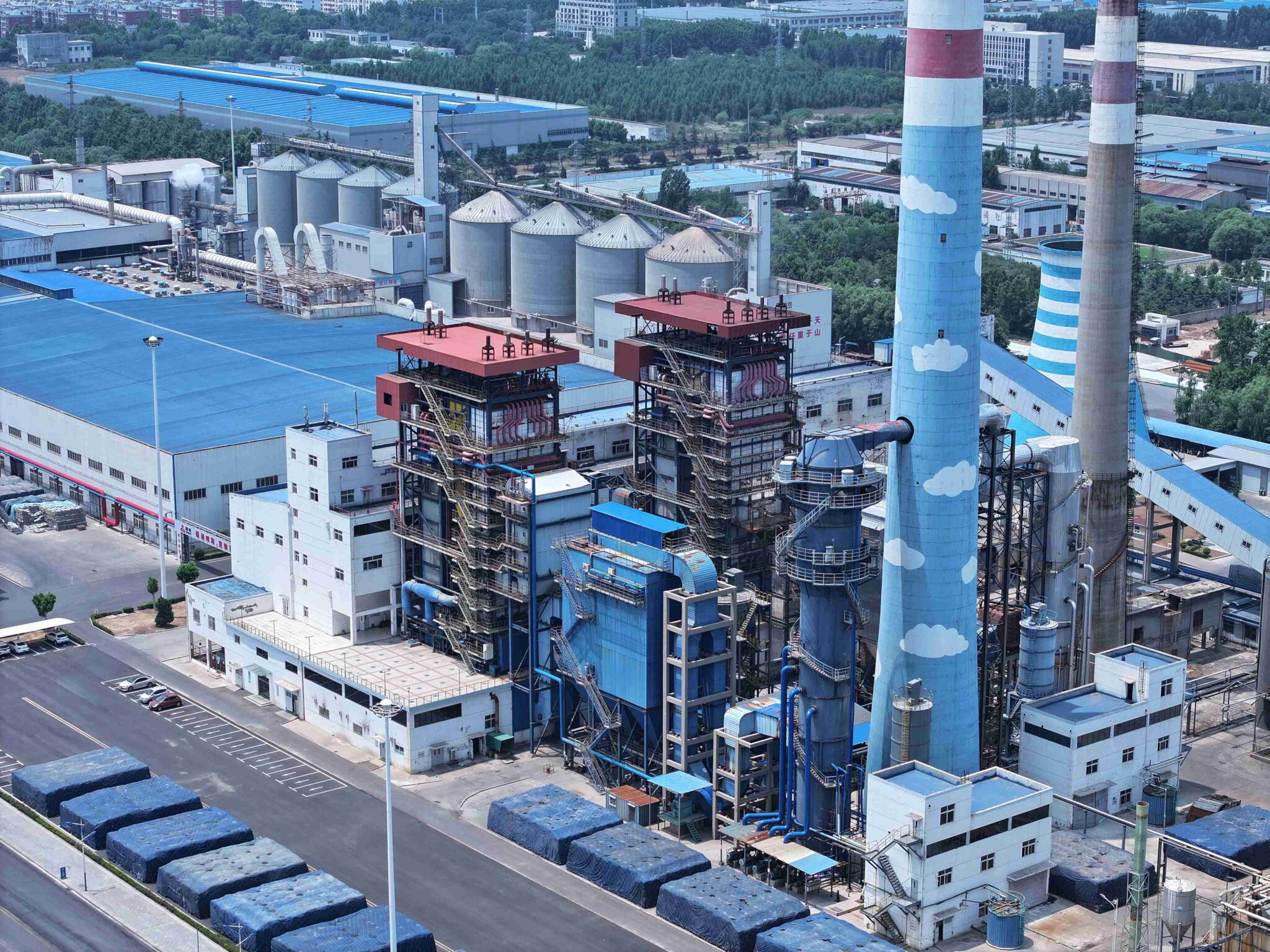
Heat Transfer Surface Condition Monitoring: Tubes, Superheaters, Economizers, and Air Preheaters
Heat transfer surface failures account for the majority of forced outages in CFB boilers — not refractory, not bed material, not instrumentation. Tubes. And the frustrating part is that most tube failures are detectable weeks or months before they become catastrophic, if you have a systematic monitoring approach rather than relying on operators noticing something unusual at 2 a.m.
The Four Failure Mechanisms, Ranked by How They Actually Present in Practice
External erosion from circulating bed particles is the dominant mode. It’s gradual, it’s predictable in location, and it’s completely manageable if you track it. The areas to watch are the lower furnace membrane wall panels (roughly 1–4 m above the air distributor grid), the superheater pendant bends where particle-laden gas turns, and any tube section immediately downstream of a cyclone return leg. Erosion here is not random — it concentrates at predictable geometry-driven impingement zones.
High-temperature oxidation and sulfidation corrosion becomes relevant above roughly 450 °C metal temperature, which in practice means final-stage superheater tubes in units generating steam above 4 MPa / 400 °C. Sulfidation is particularly aggressive when the local gas environment oscillates between oxidizing and reducing conditions — something that happens in CFB furnaces more than plant engineers expect, especially during load-following operation. You won’t see this on a weekly walk-around. You find it during ultrasonic thickness testing or, sometimes, during a tube failure post-mortem.
Internal corrosion from poor feedwater chemistry is the insidious one. Oxygen pitting and flow-accelerated corrosion both progress silently, and by the time you see a tube failure, you’re looking at a problem that started 12–18 months earlier. Condensate return systems with seasonal contamination issues — common on sites with inconsistent production schedules — are a frequent culprit. Maintain dissolved oxygen below 7 µg/L and keep feedwater pH in the 8.8–9.3 range; deviations even for short periods accumulate damage.
Ash fouling reduces heat transfer efficiency before it causes mechanical failure, but it’s worth tracking systematically because a 15–25% reduction in economizer effectiveness is real money in fuel cost, and it often signals a soot blowing strategy that needs recalibration.
Superheater Inspection Protocol
During every annual outage, UT thickness gauge a minimum of 10% of superheater tubes, focusing on bend locations and mid-span in the high-velocity gas path. Retire any tube measuring below 80% of nominal wall thickness — at that point, remaining life is short and unpredictable. On Taishan Group CFB designs, wear-sleeve overlays are applied to superheater pendant bends in the convection gas path; in practice, this extends tube service life from roughly 40,000 hours to over 80,000 hours, which shifts the replacement from “every major overhaul” to “every second or third major overhaul.” That’s a meaningful difference in outage scope and parts cost.
Ultrasonic thickness testing of CFB superheater tubes at bend locations during annual outage can detect wall loss before it reaches the 80% retirement threshold, enabling planned replacement rather than emergency weld repair.True
UT gauging is standard industry practice for pressure-part life assessment; the 80% wall thickness retirement criterion aligns with ASME and EN 12952 tube fitness-for-service guidelines. Early detection avoids the safety risk and extended outage duration of an in-service tube rupture.
Cold-End Corrosion in Economizers and Air Preheaters
This one catches people off guard on sites switching to higher-sulfur coal mid-contract. When flue gas temperature at the economizer exit drops below the acid dew point — typically 130–150 °C for coals with 1.5–3% sulfur, though the exact threshold depends on SO₃ concentration and local moisture — sulfuric acid condenses on carbon steel fin surfaces and corrodes them rapidly. The fix is not complicated, but it requires discipline: control the flue gas bypass damper to maintain minimum metal surface temperature above the dew point, and document that limit explicitly in the O&M manual so it survives operator turnover.
On tubular air preheaters, the cold end — the last 300–500 mm of tube length on the air inlet side — is where corrosion concentrates. During annual outage, pull and inspect a sample of cold-end tubes. Cast iron or enamel-coated tubes in this zone are a worthwhile upgrade on high-sulfur fuels; the payback is usually under two years when you account for avoided replacement labor.
Membrane Wall Monitoring Without Shutdown
The lower furnace membrane wall in a CFB boiler erodes faster than most operators realize, and historically the only way to measure it was to scaffold the furnace during an outage. That’s changed. Permanent wireless UT sensor grids can now be bonded to the most erosion-exposed wall panels, providing continuous wall-loss data that feeds directly into the DCS. On Taishan Group EPC projects, integrating these sensors into the alarm system — with configurable alert thresholds, typically triggered at 15% wall loss — allows the operations team to make data-driven decisions about whether a planned outage can be deferred or needs to be advanced. Roughly speaking, installation cost for a grid covering 20–30 monitoring points runs somewhere in the range of what you’d spend on two days of unplanned outage, which makes the economics straightforward.
Tube Leak Detection and Response
A small tube leak in a CFB boiler doesn’t announce itself dramatically. What you typically see first is a slow, unexplained rise in makeup water consumption — 2–5% above baseline — followed by subtle changes in flue gas moisture readings if you have them. Acoustic leak detectors mounted on the convection pass casing can identify active leaks during operation, and they’re worth having on units above 75 t/h steam output where a delayed shutdown decision has serious downstream consequences.
The response decision tree matters: a pinhole leak in a non-critical economizer tube is manageable at reduced load (typically derate to 70–80% MCR) while you schedule an orderly shutdown within 24–48 hours. A leak in a superheater tube, or any leak showing rapid growth in make-up water demand, warrants immediate shutdown. Weld repairs on pressure parts must meet ASME Section IX or the applicable national standard — in practice, this means your plant needs a qualified welding procedure and at least one certified welder on site or on short call, not sourced ad hoc after the failure happens.
Soot Blowing: More Damage Than People Expect
Aggressive soot blowing is one of the more common self-inflicted tube wear mechanisms in CFB convection passes. Steam lance pressure for CFB convection pass soot blowers should be calibrated to the minimum effective level — typically 0.8–1.2 MPa, though some designs operate well at 0.8 MPa if the fouling is light. Running every blower at maximum pressure every cycle because “it’s what we’ve always done” creates localized erosion patterns that show up as crescent-shaped wear on tube crowns facing the lance.
Rotate blowing sequences. If you always blow zone A before zone B, zone A tubes accumulate disproportionate wear over a year of operation. A simple rotation schedule — documented, enforced, logged — distributes that wear across the full tube bank and meaningfully extends the interval before you need to replace tube sections.
Emissions Control Equipment Maintenance: Fabric Filters, Desulfurization Systems, and SNCR/SCR Integration
Emissions control equipment doesn’t get the same maintenance attention as the furnace or heat transfer surfaces — until a permit violation shows up, at which point it becomes the most expensive problem on site. Regulators in most jurisdictions don’t distinguish between a mechanical failure and negligence. A broken bag row or a drifted CEMS calibration looks the same on an inspection report.
Fabric Filter (Baghouse) Maintenance
Pulse-jet cleaning valve condition is the first thing to check on a monthly basis. A failed solenoid valve on a pulse row means that row never cleans; differential pressure across the baghouse climbs steadily and you start losing draft margin. In practice, a well-run plant keeps a few spare solenoids and diaphragm valves on the shelf — Goyen and Pentair valves are common in this service — and swaps them at the first sign of sluggish response rather than waiting for full failure.
DP trending is your early-warning system. Normal operating differential pressure across a fabric filter on a CFB flue gas stream typically runs somewhere in the 1,200–2,000 Pa range, depending on bag age, dust loading, and flue gas moisture. A gradual upward trend over weeks means bag blinding — fine particulate or condensed moisture clogging the fabric. A sudden drop in DP accompanied by rising stack opacity is the opposite problem: a broken bag row, and that combination is essentially a confirmed diagnosis. Don’t wait for the opacity alarm to trend; act on the DP anomaly first.
Full bag replacement intervals vary more than vendors admit. Flue gas temperature, moisture content (biomass co-firing makes this worse), and particulate loading all shorten bag life. Expect 3–5 years in a reasonably clean coal-fired CFB; closer to 2–3 years if you’re co-firing high-moisture biomass or running above 150 °C inlet temperature with temperature spikes. Budget for this in your long-term maintenance plan — bag changeouts are not cheap and require a full baghouse outage of 3–7 days depending on unit size.
In-Furnace Limestone Injection System
Limestone bridging in day bins is one of those problems that looks minor until it causes an SO₂ exceedance at 2 a.m. on a Sunday. Moisture infiltration — from humid climates, rain ingress, or simply condensation — turns fine limestone powder into a solid plug at the bin outlet. Install bin vibrators and aeration pads as standard equipment, not optional upgrades. Check aeration pad function quarterly; they clog too.
The Ca/S molar ratio target of 1.8–2.5 for 80–90% SO₂ capture is a working range, not a fixed setpoint. The right value depends on limestone reactivity (surface area per gram varies meaningfully by quarry source), furnace temperature, and sulfur content in the fuel. If your fuel sulfur fluctuates — which it does whenever a coal supply changes — a fixed feed rate will either waste sorbent or allow exceedances. Real-time SO₂ CEMS feedback to the limestone feed rate controller is the correct solution. Run it in closed loop.
Limestone particle size significantly affects sulfation efficiency in CFB in-furnace desulfurizationTrue
Quarterly particle size analysis of the limestone feed is worth doing — target d50 below 0.3 mm. Suppliers sometimes shift grinding specifications without notice, and you’ll see it in your sorbent consumption before you see it anywhere else.
Wet or Semi-Dry FGD Scrubber Systems
Not every CFB installation runs a downstream wet scrubber, but where it’s present — typically on larger units or in regions with strict SO₂ limits below what in-furnace desulfurization alone can achieve — the maintenance burden is real and specific. Spray header nozzle patterns should be checked weekly during operation where access permits; clogged nozzles create dry zones in the scrubber vessel where sulfate can crystallize and build up on walls.
Slurry pump wear rings in limestone slurry service last roughly 6,000–8,000 hours before clearance opens up enough to affect pump head and efficiency. Track hours on each pump and stage replacements so you’re not replacing all wear rings simultaneously during an outage. Mist eliminator sections need periodic water washing — the frequency depends on slurry chemistry and flow rates, but monthly is a reasonable default — to prevent sulfate crystallization that eventually blocks passages and drives up scrubber pressure drop.
SNCR Urea/Ammonia Injection System
SNCR is temperature-sensitive in a way that’s easy to forget during normal operation. The effective injection zone window runs roughly 850–1,050 °C; outside that range, urea or ammonia either decomposes too aggressively or doesn’t react with NOx at all, and you’re injecting reagent for nothing while ammonia slip climbs. Correlate injection zone temperatures with the nearest furnace thermocouple readings and flag any periods where the furnace is running outside the design temperature window — not just for refractory reasons, but because your SNCR is probably underperforming during those same periods.
Injection nozzle tips accumulate urea deposits during low-load or shutdown periods. Inspect and clean every planned outage without exception. A partially blocked tip skews the spray pattern across the furnace cross-section, creating NOx hot spots that even increased reagent flow won’t fix. This is a ten-minute job that prevents a non-compliance event.
CEMS Calibration and QA/QC
Quarterly span gas calibration of SO₂, NOx, CO, O₂, and opacity analyzers is the minimum in most regulatory frameworks. Keep calibration records organized and accessible — environmental authorities in most export markets (Southeast Asia, the Middle East, Africa) are increasingly requiring documentation traceability going back 2–3 years. A CEMS that reads correctly is also your operational feedback tool; a drifted analyzer hides real process changes.
Taishan Group EPC contracts include a first-year CEMS calibration service package as part of the commissioning handover, which gives operators time to develop in-house calibration competency before that support transitions to the plant team.
Ash Handling System
Rotary airlock feeder clearance deserves more attention than it typically gets. Excessive tip clearance — from normal wear on cast iron or Ni-hard tips — allows false air in-leakage back into the flue gas duct, which disrupts furnace draft balance and shows up as unexplained draft fluctuations that operators often chase in the wrong direction. Check clearances at every major outage and track the wear rate; on high-ash coals, tip life can be as short as 8,000–12,000 hours.
Chain drag conveyors and belt conveyors handling fly ash and bed ash should have visual wear inspections monthly. Fly ash silo level sensor calibration is easy to overlook until a silo overflow incident creates a housekeeping and safety problem — and in some jurisdictions, a reportable environmental incident. Calibrate level sensors annually at minimum, or after any silo cleaning outage.
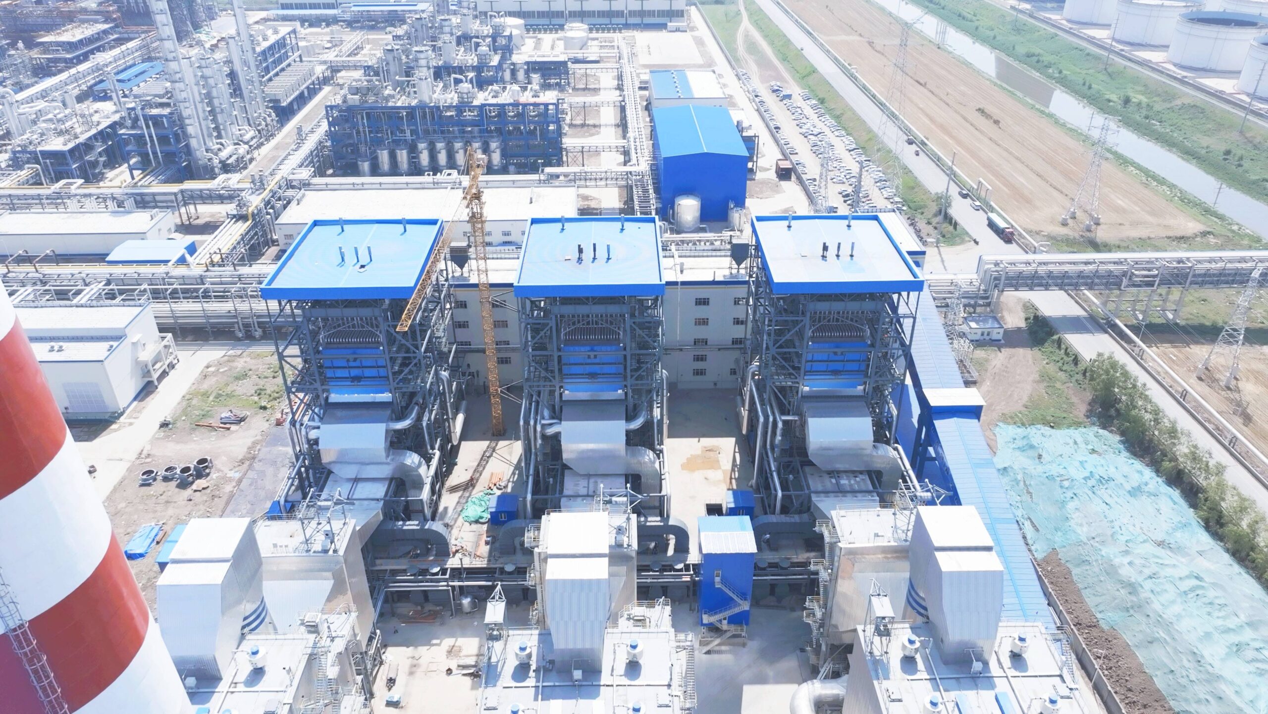
Instrumentation, Controls, and Safety System Verification for CFB Boilers
Mechanical wear gets most of the attention in CFB maintenance planning, and understandably so — refractory and nozzle grids are visible, tactile problems. But instrumentation failures and unverified safety trips are responsible for a disproportionate share of forced shutdowns and, more seriously, for the incidents that happen when a shutdown doesn’t trigger when it should. A thermocouple that reads 40 °C low doesn’t announce itself. It just quietly lets your bed temperature drift above 950 °C while the control system thinks everything is fine.
Thermocouple and RTD Calibration in the CFB Environment
Bed temperature sensors degrade faster in CFB service than in almost any other boiler application. The combination of abrasive bed material at 850–950 °C, sulfur-containing flue gas, and the physical vibration from fluidization erodes protection tubes and causes gradual reference junction drift. In practice, sensors that passed acceptance testing at commissioning can develop errors of 20–50 °C within a single operating campaign — sometimes faster if the bed is running coarse material or if the Ca/S feed ratio has been elevated to chase SO₂ targets.
Verify every bed temperature thermocouple against a calibrated portable reference probe at least every three months. Any sensor showing more than 15 °C deviation from reference should be replaced before the next operating cycle, not at the next convenient outage. Bed temperature is the primary combustion control variable; letting a drifting sensor stay in service because replacement is inconvenient is how you end up with localized sintering or accelerated refractory wear that costs far more to fix.
Pressure Transmitters and Differential Pressure Cells
Impulse lines on CFB boilers are uniquely prone to ash bridging, particularly on furnace draft and wind box differential pressure taps. Monthly purging is the baseline — on some fuels with high fine-particle carryover, you may need to do it every two weeks. A blocked impulse line gives you a frozen or drifting DP reading, and if that’s your wind box–to–furnace differential, you’re flying blind on fluidization quality.
Annual calibration against a dead-weight tester or certified reference standard is the minimum. Priority instruments: furnace draft, wind box pressure drop, steam drum pressure, and cyclone inlet DP. These four readings collectively tell you whether fluidization is intact, whether the combustion chamber is operating within its structural pressure limits, and whether your gas–solid separation is performing as designed. If any of these transmitters is on a three-year calibration cycle because “it’s never been wrong,” that’s a risk exposure, not a maintenance achievement.
Safety Instrumented System Functional Testing
IEC 61511 requires that safety instrumented functions in process plant boiler applications be proof-tested at intervals consistent with the required risk reduction — which for most CFB safety trips means at least annual functional verification.True
IEC 61511-1 establishes requirements for proof test intervals tied to the safety integrity level (SIL) and the dangerous failure rate of the SIF; annual testing is a common minimum for SIL 1–2 loops in industrial boiler applications, though the specific interval must be derived from the SIL verification calculation for each loop.
Test every hardwired safety trip — low drum level, high furnace pressure, loss of fluidization signal, induced draft fan trip, forced draft fan trip — during each planned outage. Don’t simulate at the DCS; stroke the actual field devices and confirm the final elements respond. Document the results in a safety case file. This isn’t bureaucratic overhead; it’s the evidentiary record that demonstrates due diligence if a regulator or insurer asks questions after an incident.
Alarm rationalization deserves a specific annual review. Nuisance alarms — ones that operators silence reflexively because they fire constantly — have been identified as a contributing factor in multiple CFB-related operational upsets worldwide. A well-configured alarm system should present operators with actionable information, not background noise. Review alarm activation frequency logs annually; any alarm that fires more than roughly ten times per operating day without a legitimate process cause is a candidate for rationalization or suppression.
Fuel Feed Instrumentation and Drive Health
Gravimetric and volumetric feeder calibration should happen monthly. Fuel feed rate accuracy ties directly to combustion stability and, for any unit running in-furnace desulfurization with limestone injection, to emissions compliance. A feeder running 8–12% high on fuel — which is entirely possible after a load cell drift — throws off your excess air ratio, your bed temperature control, and your Ca/S ratio simultaneously.
Check variable frequency drives on feeder motors quarterly for overtemperature and harmonic distortion. VFD failures tend to be gradual, showing up first as intermittent speed irregularities before becoming hard faults. Catching them quarterly costs almost nothing; a failed feeder drive during a peak-load period can force a load curtailment or a cold restart.
Connecting Condition Data to Your CMMS
Most of this verification work generates data that should be feeding your maintenance management system, not living in paper logbooks. Taishan Group’s CFB control systems support MODBUS and OPC-UA data export, which allows integration with third-party CMMS platforms — SAP PM, IBM Maximo, or equivalent — to generate work orders automatically when sensor drift or anomalous DP trends cross defined thresholds. For overseas industrial clients and EPC developers managing multi-unit sites across time zones, that kind of automated trigger is increasingly the difference between reactive and genuinely predictive maintenance.
The configuration backups deserve a separate mention: DCS and SCADA controller images and historian databases should be backed up quarterly, stored off-site or in a secure cloud environment, and tested for restore integrity at least once a year. A controller failure after a lightning event is painful enough without discovering that the last verified backup is eighteen months old.
Developing a Site-Specific CFB Boiler Maintenance Program: From Generic Checklist to Living Document
The OEM manual that ships with a CFB boiler is a baseline, not a program. It’s written to cover the broadest possible range of operating conditions, which means it’s often too conservative in some areas and dangerously silent in others. A boiler burning low-sulfur anthracite in northern Europe operates in a fundamentally different degradation environment than the same pressure class unit burning palm kernel shell in coastal Malaysia — same steel, same refractory grade, completely different failure modes, completely different intervals that actually matter.
Building a real maintenance program starts with fuel characterization. Before you write a single inspection interval, you need the ash fusion temperature, chlorine content, alkali index (roughly (K₂O + Na₂O) / (SiO₂ + P₂O₅) from proximate and XRF data), and total sulfur of the actual fuel you’re running — not the spec-sheet fuel, the delivered fuel. These four parameters together tell you which degradation mechanisms will dominate.
Why Fuel Chemistry Rewrites Your Maintenance Calendar
Take a straightforward comparison: a 75 t/h CFB unit running washed bituminous coal at 0.6% sulfur versus the same boiler switched to palm kernel shell (PKS). The coal case is relatively well-behaved — your primary concerns are refractory erosion in the cyclone return leg, bed temperature drift, and gradual superheater wall thinning. Inspection intervals in the OEM manual are probably reasonable starting points.
PKS changes everything. Alkali index for PKS typically runs 3–6 times higher than for bituminous coal. That means accelerated fireside corrosion on superheater tubes, higher risk of bed agglomeration from low-melting alkali silicates, and chlorine-driven under-deposit corrosion that can perforate a tube in under 12,000 hours if you’re not watching. In practice, I’d shorten superheater UT inspection intervals from the standard 8,000-hour recommendation down to 4,000–5,000 hours, mandate weekly bed sample sieving to catch the early signs of agglomeration, and re-specify the refractory lining in the upper furnace for higher alkali resistance. The OEM manual won’t tell you any of that.
The Four-Tier Program Structure
Organizing the program into tiers gives you clear ownership and prevents tasks from falling into a grey zone where nobody is accountable.
| Tier | Frequency | Owner | Key Documentation |
|---|---|---|---|
| 1 | Daily / per shift | Licensed boiler operator (Grade II minimum) | Shift log, digital checklist |
| 2 | Monthly / quarterly | Plant maintenance technician | Work order records, trend database |
| 3 | Annual planned outage | Maintenance engineer + specialist contractors | Outage scope report, RCA inputs |
| 4 | Lifetime assessment (~100,000 operating hours) | Senior engineer + OEM/EPC partner | Fitness-for-service report, capex recommendation |
Escalation rules matter as much as the tiers themselves. A Tier 1 operator who finds air distributor pressure drop creeping up by more than 15% above baseline should not be closing that log entry and walking away — that observation needs to reach a Tier 2 technician within 24 hours, with a decision on inspection timing made before the next shift.
KPIs That Tell You Whether the Program Is Working
Target overall equipment effectiveness above 92% for a well-run industrial CFB. Forced outage rate should stay below 2% annually — if you’re running 6–8%, the maintenance program isn’t the only problem, but it’s usually a large part of it. Mean time between failures for refractory should exceed 18 months; for pressure-part tubes, aim for better than 60,000 hours between repairs; for forced-draft and induced-draft fan bearings, 30,000 hours between replacements is achievable with proper lubrication management and vibration trending.
When these numbers slip, the response shouldn’t be ad-hoc repairs. Conduct a formal Root Cause Analysis within 72 hours of any unplanned outage — 5-Why works fine for straightforward failures, fishbone is better when multiple systems interact. Update the maintenance program and spare parts stock list based on findings. This loop is what converts a static document into a living one.
Generic OEM maintenance manuals alone are sufficient for CFB boiler maintenance program managementFalse
OEM manuals provide baseline intervals calibrated to generic operating conditions. Site-specific factors — actual fuel chemistry, local climate, water quality, and operational profile — all shift failure modes and appropriate inspection intervals significantly. A plant running high-alkali biomass fuels will experience corrosion and agglomeration failure modes that a standard coal-spec manual does not adequately address.
Competency and Continuous Improvement
None of this works without qualified people executing it. On high-pressure CFB units, shift supervisors should hold at minimum a Grade I boiler operator certification; operators on watch should hold Grade II. These aren’t bureaucratic boxes — the difference in fault recognition between a certified and uncertified operator under abnormal conditions is real and measurable in outage statistics.
For overseas projects, Taishan Group includes factory-based operator training and on-site commissioning training as part of EPC and equipment supply contracts, which gives plant teams direct access to the design engineers who built the unit. Anonymized failure data from the field feeds back into product improvement cycles — a tube failure mode identified on a Southeast Asian biomass plant, for example, has influenced refractory geometry updates on subsequent units. That feedback loop is only possible when the maintenance program generates structured, documented data rather than informal shift handover notes.
The program is never finished. Every outage, every anomaly, every near-miss is input data. Treat the document accordingly.
Frequently Asked Questions About CFB Boiler Maintenance
How often does the refractory lining actually need to be replaced?
Inspection every 4,000–8,000 operating hours is the baseline — or annually, whichever arrives first. In practice, partial repairs and tile replacements happen on the 18–24 month overhaul cycle, targeting the top five wear zones: the furnace lower combustion chamber, cyclone inlet throat, loop seal return leg, and the splash zones around secondary air ports. A full reline is a much larger commitment and typically falls somewhere in the 6–10 year window, depending heavily on fuel abrasiveness and what refractory material grade was specified originally. Plants burning high-ash coal or agricultural residues with silica-rich ash tend to push toward the shorter end of that range. High-alumina castables and SiC-bonded tiles earn their premium by extending full reline intervals noticeably — sometimes adding two or three years before full replacement becomes unavoidable. Don’t let anyone sell you a single number here; the answer depends on the plant.
What actually causes most unplanned shutdowns?
In rough order of frequency across the plants I’ve seen data from: air distributor nozzle blockage leading to bed defluidization, refractory spall causing accelerated tube erosion, and drum water level control failure. Nozzle blockage is probably the most insidious because it develops gradually — you can have 3% of nozzles clogged and the process looks roughly normal, but by the time you’re past 5% the fluidization pattern deteriorates fast and localized hot spots form at the bed. All three failure modes are predictable and largely preventable with the inspection routines covered earlier in this article.
Can the boiler keep running if there’s a small tube leak?
A confirmed pinhole leak is not a “monitor it for a week” situation. You might have hours, not days. Steam jet erosion on an adjacent waterwall tube can perforate that neighboring tube within roughly 8–24 hours once the leak is established — the geometry of a waterwall panel makes this especially dangerous because tubes are close together and the jet angle is often directly onto the next surface. The practical guidance: prepare a controlled shutdown immediately, notify the shift supervisor and plant engineer, and treat any delay beyond one to two shifts as an elevated risk decision, not routine operations. Get the unit down cleanly while you still control the timing.
What happens to the maintenance schedule if you switch fuels?
More than most operators expect. Moving from a design fuel like bituminous coal to a higher-chlorine fuel such as agricultural biomass changes the corrosion chemistry on superheater tubes, shifts bed material management requirements (particle size, replacement frequency), and often requires revised limestone dosing to maintain your Ca/S ratio in the 1.8–2.5 range for adequate SO₂ capture. If the fuel switch is permanent, re-baseline the entire maintenance program — don’t just bolt on a few extra inspection rounds and assume the rest carries over.
What spare parts should be kept on site?
At minimum: a complete nozzle grid set, refractory castable and ceramic tiles covering the top five wear zones, at least 20% reserve fabric filter bags, critical bearing sets for all fans and feed pumps, one boiler feed pump cartridge, and a set of bed temperature thermocouples. Thermocouples are cheap and fail at inconvenient moments; there’s no good reason to run without spares. Taishan Group provides a recommended spare parts list with every boiler delivery, sized to the specific unit capacity and configuration.
A well-maintained CFB boiler should achieve a forced outage rate below 2% annually.True
This is the established benchmark for well-maintained industrial CFB units. Plants without disciplined scheduled maintenance routinely see forced outage rates of 6–10%, representing a substantial and measurable cost penalty in lost generation or process uptime.
How do you know if the maintenance program is actually working?
Track three numbers: OEE (target above 92%), forced outage rate (target below 2% per year), and specific maintenance cost per ton of steam generated. If forced outage rate is trending upward year-over-year, or if maintenance spend is exceeding roughly 3–4% of boiler replacement value annually, the program needs a structured technical audit — not just more inspections, but a root-cause review of what’s being missed and why.
Does Taishan Group support CFB boilers after overseas installation?
Yes. Remote diagnostic support via DCS data export, annual on-site inspection service agreements, OEM spare parts and refractory kit supply internationally, and operator training programs conducted in English — either at the factory or at the client site. For plants in regions where qualified CFB service technicians are scarce, the remote diagnostic option is genuinely useful during the first few operating years while the local team builds familiarity with the unit.
References
A Review of Some Operation and Maintenance Issues of CFBC Boilers — Applied Thermal Engineering / Elsevier
Circulating Fluidized Bed Boilers — CFB Technology and Service — GE Vernova
Circulating Fluidized Bed Boilers — Valmet
Circulating Fluidized Bed Boiler Technology — Mitsubishi Power
Circulating Fluidized Bed Boilers — ANDRITZ
Fluidized Bed Boilers — Boiler Technology and Services — Babcock & Wilcox
BPVC Section VII — Recommended Guidelines for the Care of Power Boilers — ASME
Boiler Logs Can Reduce Accidents — National Board of Boiler and Pressure Vessel Inspectors
National Board Inspection Code — Boiler Inspection, Repair and Alteration — National Board of Boiler and Pressure Vessel Inspectors
Coal Analysis and Production Information — Thermo Fisher Scientific