
What Are the Correct Startup and Shutdown Procedures for Industrial Coal-Fired Boilers?
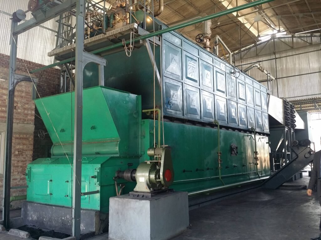
Rushing a cold-start or cutting corners on shutdown is one of the fastest ways to crack a steam drum. It happens more than plant managers like to admit — a shift supervisor under production pressure bumps the firing rate too early, pressure climbs too fast, and six months later you’re staring at a hairline fracture in a header weld that the ultrasonic inspector found during an unplanned outage. The repair bill alone can run well into the tens of thousands of dollars, and that’s before you account for lost production, emergency parts sourcing, and the regulatory inspection that now has to happen before the boiler can come back online.
The correct startup procedure for an industrial coal-fired boiler requires a cold warm-up period of roughly 4–8 hours (longer for high-pressure or large-capacity units), a steam pressure rise rate held below 0.1–0.15 MPa per 10 minutes, and a controlled shutdown sequence that includes load reduction, fuel cutoff, and a natural cooling period of 24–72 hours before any internal access — the exact times depending on operating pressure and initial metal temperature.
What most operating manuals describe in clean numbered steps rarely captures the judgment calls that actually determine whether a startup goes smoothly or turns into a metallurgical problem. The difference between a drum that lasts 25 years and one that develops stress cracking inside a decade often comes down to decisions made during the first two hours of a cold start and the last hour before a planned outage — decisions that are easy to get wrong when the plant is under pressure to produce.
Pre-Startup Inspection Checklist: Mechanical, Electrical, and Instrumentation Readiness
Before a single kilogram of coal touches the grate or enters the CFB bed, every subsystem needs a deliberate, documented check. Rushing this stage is where most preventable incidents originate — not from equipment failure in isolation, but from a known deficiency that someone decided to “watch for a while.” Don’t do that.
Pressure Parts: Drums, Valves, and Hydrostatic Test Validity
Start at the drum. Verify both water level gauges independently — the gauge glass and the remote transmitter should read within ±10 mm of each other under static conditions. Any wider discrepancy means recalibrate before you fire, not after. Safety valve lift test records should be current; most jurisdictions require proof of testing within the prior 12 months, though this varies by local boiler inspection authority and operating pressure class. If the last test shows a valve that required more than roughly 3% overpressure above the nameplate set point to open, that valve seat needs attention.
Blowdown valve seats deserve more respect than they usually get. A slow-passing bottom blowdown valve wastes treated water continuously and makes drum level control unstable during the delicate startup period. Run a simple thermal scan or listen at the downstream pipe — a hissing valve at ambient pressure is a problem. Check hydrostatic test validity while you’re at it; on units that have been idle for an extended outage, some insurance underwriters and inspection bodies require a retest after 12–18 months of inactivity.
Combustion System: Grate or Bed, Depending on Your Boiler Type
For chain-grate stokers, physically inspect grate bar clearances. Gaps wider than the design tolerance — typically 0.5–1.5 mm depending on coal seam size — cause clinker to fall into the ash pit and uneven combustion lanes to develop, which shows up later as unexplained cold zones and excess carbon in ash. Check the side-seal strips at the grate edges; these wear faster than most plants budget for, and an air bypass here goes straight to CO formation and poor efficiency.
CFB units require a different mindset entirely. Bed material level and particle size distribution govern whether you’ll achieve stable fluidization during light-off. Target particle size is typically in the 300–500 µm range — finer material risks slugging behavior; coarser material lifts poorly and causes localized hotspots near the air distributor nozzles. Measure bed inventory height and confirm it against your commissioning baseline. If the unit has been shut down for more than a week, the bed may have compacted or absorbed moisture; a short fluidization test on air alone before introducing fuel is worth the 20 minutes it takes.
Auxiliary Equipment: Fans, Feeders, and Ducts
Forced-draft and induced-draft fan bearing temperatures should be checked cold, then verified again after a 15–20 minute dry run. Lube oil pressure at the bearing housings should meet OEM specification — commonly 0.08–0.15 MPa, though this depends on the fan frame size and bearing type. Damper travel verification is frequently skipped and frequently regretted; a damper that reads 100% open in the control room but is mechanically stuck at 60% will leave you chasing an oxygen deficit in the furnace for the first two hours of operation.
Coal feeder calibration matters because startup fuel-air ratio control is only as accurate as the feeder output. Run the feeder briefly with a catch-and-weigh check if it hasn’t been used in more than two weeks.
Primary air duct seal integrity has no meaningful effect on startup performance for chain-grate boilers.False
Leaking primary air duct seals reduce under-grate air pressure, causing uneven air distribution across grate sections. This produces combustion lanes, increases unburned carbon loss, and can cause localized overheating of grate bars during the early firing stage when fuel bed depth is still establishing.
Instrumentation and Control Loop Verification
Zero and span the drum level transmitter against a known reference — a static water column calculation works fine. For furnace draft, the typical operating set point sits between -20 and -50 Pa at the furnace top; confirm the transmitter reads correctly at ambient before startup because a drifted transmitter will cause the ID fan control loop to chase a false signal, resulting in either over-ventilation (heat loss) or furnace pressurization (a safety event). Thermocouple response at the economizer outlet and superheater outlet can be checked with a quick ice-point or portable reference — sluggish response from a fouled thermowell will mask temperature excursions during the warm-up ramp.
Feedwater Quality: Non-Negotiable Before Filling
Confirm boiler water conductivity and pH before and after filling. Target pH is 10–12 for most low-to-medium pressure steam boilers using phosphate treatment; outside this range, either corrosion or scale deposition accelerates sharply. Dissolved oxygen below 0.007 mg/L is the accepted threshold — anything higher in a hot boiler invites oxygen pitting on waterwall tubes, which shows up 18–36 months later as pinhole leaks that are annoying at best, catastrophic at worst. The deaerator must be at operating pressure and temperature before feedwater is routed to the boiler; cold, oxygen-saturated water introduced during startup is one of the more reliable ways to shorten tube life.
Cold Startup Sequence Step-by-Step: From Boiler Fill to Stable Steam Supply
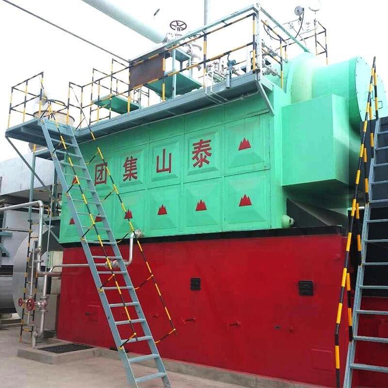
Cold startup is where most boiler damage actually accumulates over a unit’s life — not during steady-state operation, but during those first few hours when metal temperatures are uneven and thermal gradients are steepest. A 4–8 hour warm-up window is typical for industrial coal-fired units, though the lower end applies only to smaller, lower-pressure boilers (say, 1.6 MPa saturated steam units) that were shut down recently and still hold some residual heat. A large CFB boiler at 9.8 MPa that has been cold for several days will need the full 8 hours, sometimes a bit more if ambient temperature is below 5°C.
Stage 1 — Boiler Filling and Venting
Fill the drum with chemically treated feedwater — correct pH, hardness, and dissolved oxygen within spec before you start, not after. Bring the water level to the low drum level mark, not mid-drum. Expansion during heating will raise it, and overfilling at this stage leaves you chasing a high-water alarm during pressure rise.
Keep all air vents open throughout filling. Once heating begins, watch the vents: you’re waiting for a continuous, steady steam discharge before closing them. If you close vents prematurely, trapped air creates localized hot spots in headers and can cause water hammer later. On a multi-pass unit with economizer and superheater sections, each vent bank needs individual attention — don’t assume the drum vent alone confirms full purge.
Stage 2 — Ignition and Initial Firing
For stoker-fired units, the ignition box with ignition coal is standard practice. CFB units typically rely on oil or gas igniter burners mounted in the lower furnace. Either way, the target furnace draft at ignition is around −20 Pa — stable enough to establish proper airflow through the fuel bed without pulling cold air across hot refractory too aggressively.
The “slow fire” hold period of 60–90 minutes at low firing rate is non-negotiable. Refractory — especially in CFB combustion chambers — will crack if heated too quickly. In practice, operators sometimes feel pressure to cut this short when a plant is behind schedule. That is a false economy. Refractory repair on a CFB unit runs weeks and significant cost, not days.
Stage 3 — Pressure Raising Curve
Pressure rise should follow defined hold points: reach 0.1 MPa and hold 20–30 minutes, then 0.3 MPa and hold again. At 0.3 MPa, while metal is warm and flanges have expanded uniformly, tighten flange bolts and manhole fasteners. This step is easy to skip and consistently causes leaks at the first full-pressure run. Continue to 1.0 MPa with another hold, then raise to rated pressure.
The rate limit matters here: no more than 0.1–0.15 MPa per 10 minutes. That range depends on drum wall thickness and rated pressure — a thin-walled low-pressure unit tolerates the upper bound, a high-pressure drum does not.
Pressure rise rate exceeding 0.15 MPa per 10 minutes during cold startup significantly increases thermal stress cracking risk in boiler drums and headers.True
Rapid pressure rise creates steep temperature gradients across drum wall thickness, generating cyclic thermal stress that leads to fatigue cracking over repeated startups — a well-documented failure mechanism in boiler pressure vessels.
Stage 4 — CFB-Specific Bed Fluidization Startup
Before introducing coal, run a cold-air fluidization test: confirm bed material is fluidizing evenly across the entire grate, with no dead zones. Uneven fluidization predicts agglomeration. Raise bed temperature to roughly 600°C using the oil/gas igniters before any coal injection — below this threshold, volatile combustion is unstable and you risk bed defluidization from partial char buildup.
Once coal feeding starts, ramp up feed rate gradually over 30–45 minutes. Aggressive early coal injection when the bed is still cool is the primary cause of bed agglomeration in startup — essentially, low-temperature coal combustion produces sticky ash that glues bed particles together, forcing an emergency shutdown and hours of bed material replacement.
Stage 5 — Connection to the Steam Header
Warm the main steam line before cracking the isolation valve — a cold line receiving high-pressure steam will water-hammer, sometimes violently enough to damage pipe supports or valve internals. Open a drain valve on the steam line and run it for several minutes first.
Crack the main steam valve slowly, just enough to let pressure equalize across the valve seat. Once pressure differential drops below roughly 0.05 MPa, you can open fully. For superheated steam units — a 9.8 MPa/540°C unit is a common industrial configuration — verify superheater outlet temperature is within ±5°C of rated value before declaring stable supply. Chasing load with an under-temperature superheater causes wet steam carryover into turbines or process equipment downstream.
Documentation at Every Milestone
Log time, drum pressure, steam temperature, drum water level, and furnace draft at each hold point. This is partly regulatory compliance and partly practical engineering: startup logs from the first 20 cycles of a new boiler are genuinely useful for identifying trends — a creeping warm-up time, for instance, often indicates scaling in the economizer before any other symptom appears. Keep the records, and actually review them periodically.
Warm Startup and Hot Startup Procedures: Reducing Restart Time Safely After Short Outages
Not every restart is a cold start, and treating them all the same way wastes time, fuel, and — more seriously — risks thermal shock to components that are still hot and under residual stress. The distinction matters.
Warm vs. Hot Startup: Different Residual Conditions, Different Risk Profiles
A warm startup applies when the drum metal temperature sits somewhere between 100°C and 200°C and residual steam pressure is above roughly 0.05 MPa but below 0.3 MPa — typical after an overnight or weekend outage of 12–36 hours. The boiler has cooled partially but retains meaningful stored heat in the refractory, drum, and headers.
A hot startup is a different animal entirely. Residual pressure is still above 0.3 MPa, the outage has been under 8 hours (often just a few hours for a load-following industrial plant), and the drum and superheater headers may still be at or near operating temperature. The risk here isn’t sluggishness — it’s doing too much too fast. With thick-walled components already near thermal equilibrium, any sudden quench from cold attemperator water or a surge of wet steam can induce localized stress that accumulates cycle by cycle. That kind of damage doesn’t announce itself immediately; you find it during the next scheduled NDT inspection, or worse, you don’t find it at all until a header crack propagates.
Condensate Drainage: The Step That Gets Skipped Under Pressure
In a fast hot restart, the temptation is to get steam to the header and notify the process team you’re back online. Resist it. Steam lines and branch headers that have been idle — even for four or five hours — collect condensate, and depending on the pipe routing and trap condition, that condensate doesn’t drain itself reliably. Before any pressure rise resumes, drain all low-point drains on the main steam line and branch headers manually. Crack the isolation valves slowly and listen. A healthy drain sounds like a clean hiss; a water-hammer risk sounds like intermittent thuds or a sudden surge of liquid. This step takes maybe 15–20 minutes and has saved more than a few flanged joints and valve bodies from being replaced unnecessarily.
Accelerated Pressure Rise: When It’s Permissible and What Still Governs
During a hot restart with residual pressure above 0.3 MPa, the intermediate hold points in the pressure-rise schedule can often be shortened — sometimes eliminated entirely if the drum temperature differential (inner wall vs. outer wall) is confirmed within acceptable limits, usually ≤40–50°C depending on the drum thickness class. However, superheater metal temperature is a hard ceiling regardless of restart type. Most industrial superheaters are designed for a maximum metal temperature of around 560°C; pushing coal feed rate before adequate steam flow is established through the superheater — and it’s always a steam-flow-to-metal-temperature relationship, not just a pressure number — invites local overheating of pendant elements that have no cooling until steam is flowing. Ramp coal feed rate up in stages of roughly 10–15% of rated capacity, with at least a 5–8 minute hold at each stage to let temperatures stabilize.
The intermediate pressure hold steps can always be skipped during a hot restart to save timeFalse
Skipping holds is only permissible when drum wall temperature differentials are within design limits and superheater metal temperatures are confirmed safe. Rushing the ramp-up without these checks risks thermal fatigue cracking in drum walls and superheater headers.
CFB Hot Restart: Bed Temperature Distribution Comes First
For circulating fluidized bed units, hot restart carries a specific hazard that stoker boilers don’t have: uneven bed temperature distribution after a short shutdown. The bed material retains heat, but not uniformly — the bottom of the bed near the air distributors cools faster than the upper bed zone, and localized hot spots can persist in areas with poor fluidization during the idle period. Before re-injecting coal, verify bed temperature at multiple measurement points (most well-instrumented CFBs have 6–12 bed thermocouples at varying heights and circumferential positions). If the spread across measurement points is more than roughly 80–100°C, run on secondary air only for a few minutes to re-homogenize before coal feed starts. Ignoring this can concentrate combustion in already-hot zones, sinter the bed material locally, and create defluidization — which on a hot restart can go from manageable to a forced emergency shutdown faster than it would during a cold start.
Coordinating with Downstream Processes
This part is operational rather than mechanical, but it’s where restarts actually fail in practice. Steam consumers — autoclaves, process heat exchangers, turbine inlet valves, or drying lines — need advance notice of 15–30 minutes minimum before steam supply resumes, and they need confirmation of steam quality before any process-critical valve opens. Dryness fraction and, for superheated systems, confirmed superheat temperature should be verified at the boiler outlet. Routing steam through the bypass line or blow-off until quality is stable is not optional; it’s standard practice. A turbine control valve hit with wet steam during a hot restart that was rushed by 10 minutes is an expensive lesson.
Normal Shutdown Procedure: Controlled Load Reduction and Safe Pressure Release
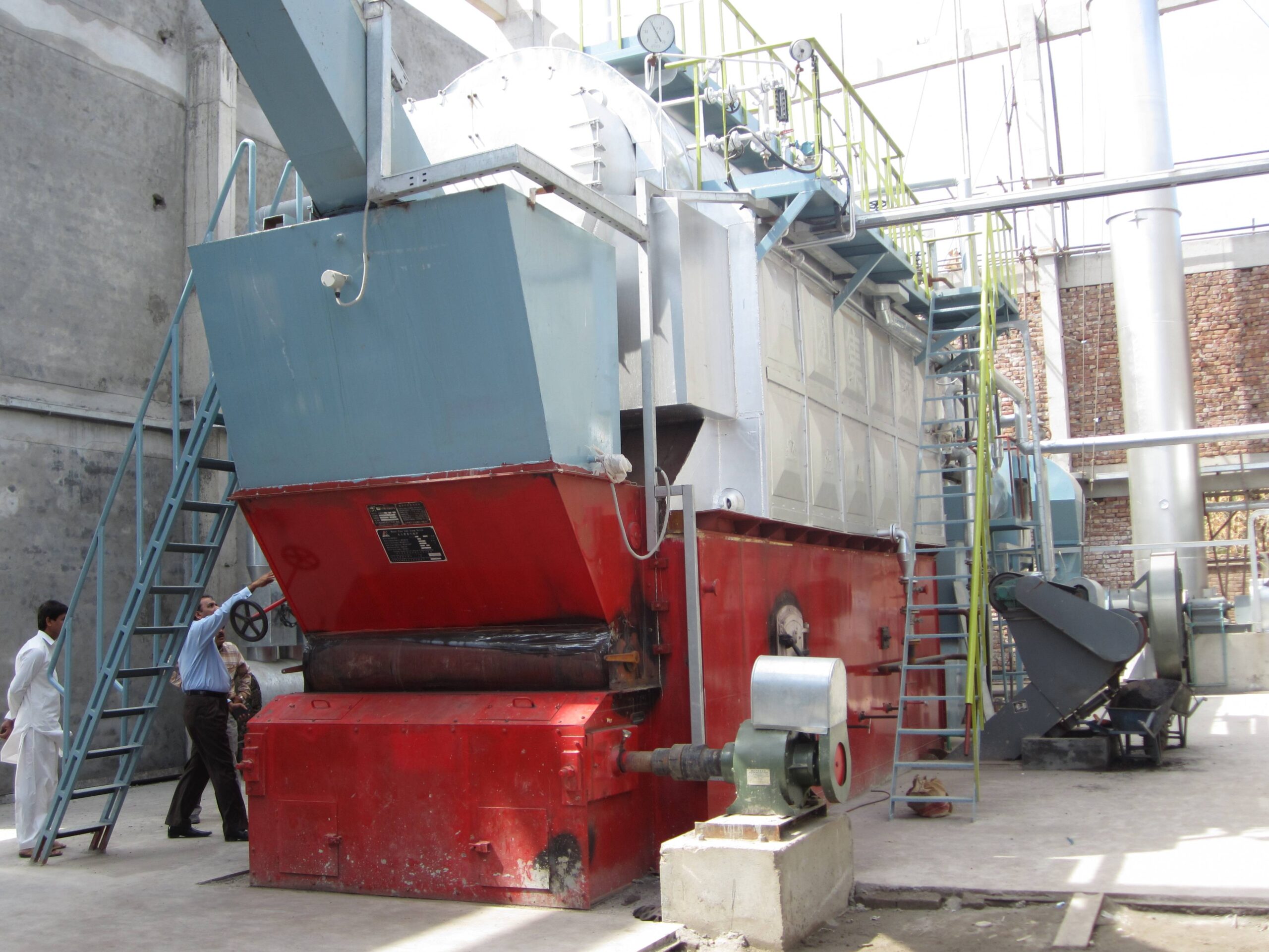
A planned shutdown done carelessly causes the same cumulative damage as a dozen bad startups. Thermal gradients tear at drum welds, acid condensate attacks ESP internals, and smoldering char in a sealed furnace builds CO to dangerous levels. The sequence below assumes a full planned outage — not an emergency trip — on a stoker-fired or CFB unit operating at normal working pressure.
Load Reduction: Step Down Together, Not One at a Time
Begin reducing load at least 2–3 hours before the target shutdown time, depending on boiler capacity and how your steam consumer (process plant, turbine, header system) can absorb the ramp-down. The rule of thumb most operators work to is no more than 10–15% of rated steam output per 15-minute interval. That pace matters because drum metal and refractory don’t cool uniformly — push faster and you introduce differential thermal stress that shows up as hairline cracks in drum nozzle welds two or three outages later, not immediately.
Cut coal feed rate and combustion air together. This is the part operators most often get wrong: they reduce the stoker speed but leave the FD fan at the old setting, which drives excess air through the bed, drops furnace temperature faster than the pressure parts can follow, and wastes fuel. Maintain your target excess air ratio (typically 20–30% excess for chain grate stokers, somewhat higher for CFB during rundown) by trimming FD and ID fans in proportion. Your O₂ trim controller, if fitted and calibrated, should handle this automatically — but verify it’s actually following, not just indicating.
Burnout Phase: Don’t Close the Fans Too Early
Once coal feed stops, the grate or CFB bed still holds live char. On a chain grate stoker this burnout phase typically runs 20–40 minutes; on a CFB with a deep bed inventory it can stretch longer depending on bed mass and coal reactivity. Keep both FD and ID fans running at reduced but adequate flow during this entire period. Closing the fans on residual char is a genuine hazard — CO accumulates in the gas passes, and if a door or damper leaks air in later, the result ranges from a backpuff to something worse.
Watch your CO monitor during burnout. When CO at the stack drops back to near-ambient and you can see through the inspection port that the grate is clear, the bed is spent.
Drum Pressure Bleeddown
After fans stop, you have two practical options: crack the main steam stop valve slightly and let pressure bleed to the header (useful if the steam system can accept it), or use the continuous blowdown line to release pressure more slowly with the unit isolated. Either way, the target is to keep drum water level at normal working level — don’t let it drop — until drum pressure falls below roughly 0.1 MPa. Below that threshold thermal gradients are manageable and the risk of steam flashing from residual water into low-pressure steam pockets diminishes substantially.
Steam pressure should not fall faster than about 0.1–0.15 MPa per 10 minutes during bleeddown, the same rate discipline applied during startup. It feels slow. It is slow. That’s deliberate.
Resist the temptation to open drain valves wide to accelerate cooling. Rapid quenching of superheater tubes and economizer sections is a reliable way to generate tube failures that won’t show up until the next hydrostatic test — or until a tube bursts under load.
Allowing remaining coal to fully combust before shutting combustion air fans prevents CO accumulation in the flue gas passes.True
Residual char consuming oxygen post-fan-shutdown produces CO in a confined gas path. With fans running, CO is continuously purged to stack. Sealing the system with active char present is the mechanism behind CO buildup incidents during uncontrolled or hasty shutdowns.
Ash and Slag Management
While pressure bleeds down, the ash system needs attention. Dump hopper ash — bottom hopper, economizer hopper, and any cyclone or convection pass hoppers — before the unit cools, because cooled fly ash with any moisture picks up sulfuric acid and becomes difficult to move and corrosive to screw conveyors. Seal the ash conveyor system once hoppers are empty.
Isolate the ESP or bag filter as soon as flue gas temperature drops below roughly 120–130 °C (the exact threshold depends on your fuel sulfur content and the dew point calculation for your flue gas). Leaving collection surfaces exposed to slowly cooling, sulfur-laden gas causes acid condensation on plates or bags. In practice, you’ll see this as severely corroded ESP discharge electrodes or blinded bag filter sections when you open up for maintenance — damage that’s entirely avoidable.
Final Isolation and LOTO
With pressure at or near zero and the unit thermally stable, work through the isolation checklist in order:
| Isolation Point | Action | Notes |
|---|---|---|
| Main steam stop valve | Close and lock | Verify downstream header pressure doesn’t back-feed |
| Feedwater stop valve | Close | Prevent pressurization from feed system |
| All drain and blowdown valves | Close and cap | Confirm no weeping |
| FD / ID / PA fans | De-energize and LOTO | Tag at MCC, not just local isolator |
| Feedwater pumps | De-energize and LOTO | Include standby pump |
| Coal feeders / stoker drive | De-energize and LOTO | Lock out belt/chain drives physically |
| ESP / bag filter power | De-energize and LOTO | High-voltage sections require discharge verification |
Don’t skip the physical lockout because the unit “looks cold.” Feedwater systems in particular can re-pressurize drum sections from a live header if the stop valve isn’t positively isolated. That’s a confined-space entry hazard when your inspection crew opens the manhole 24–72 hours later — the exact waiting period depending on your working pressure, with higher-pressure units (say, 9.8 MPa) requiring the longer end of that range before any entry.
Emergency Shutdown Triggers and Immediate Response Actions
Not every shutdown is planned. Emergency trips happen — sometimes at 2 AM, sometimes mid-shift when a gauge reading creeps past a threshold and the operator has maybe thirty seconds to make the right call. Getting this wrong doesn’t just mean equipment damage; it means tube ruptures, drum cracking, and in the worst cases, catastrophic pressure-part failure.
Conditions That Mandate an Immediate Trip
There are four conditions that require pulling the emergency stop without hesitation, without waiting to see if the reading “corrects itself.”
Drum water level below the lowest visible gauge limit. If the water level drops out of sight on the gauge glass, you are beyond low-low level — you’re operating blind. Continued firing at this point risks dry-fire tube overheating within minutes. Localized tube wall temperatures can climb fast enough to cause creep failure before the operator has completed a second check.
Steam pressure exceeding safety valve set pressure by more than 3% with no valve lift. Safety valves stick. It happens more often than manufacturers would like to admit, particularly on units that have been sitting idle or that have accumulated mineral deposits on the valve seat. If pressure is climbing past that 3% margin and the safety valve hasn’t opened, do not wait.
Boiler feedwater pump failure with no standby available. A single pump trip with an operational standby is a normal operating event. No standby means no controlled water make-up, and the clock starts immediately.
Furnace explosion or tube rupture. These are rarely ambiguous — a tube rupture produces a distinctive roar and a rapid pressure drop accompanied by steam escaping into the furnace. A furnace puff or minor explosion may be subtler, but any abnormal pressure wave in the furnace envelope triggers the same response.
Immediate Action Sequence
Trip the coal feeder first — stop fuel input before anything else. Then trip the induced draft (ID) fan, followed by the forced draft (FD) fan. The order matters: cutting FD before ID risks pressurizing the furnace and pushing combustion gases back through the air ducts.
If pressure continues to rise after the fuel trip, open the drum vent and the safety valve bypass manually. Maintain minimum feedwater flow to keep tubes wetted and carry heat away from the furnace walls — but do not inject cold water aggressively into a hot drum. The thermal shock from rapid cold-water injection into a drum running at, say, 3.8 MPa and 250°C can cause stress cracking in the drum shell or nozzle welds that won’t show up until the next hydrostatic test, or worse, the next startup.
CFB-Specific Emergency: Bed Temperature Runaway
Circulating fluidized bed units have an additional failure mode that stoker-fired boilers don’t: bed temperature runaway. If bed temperature climbs above roughly 950°C — and it can get there faster than operators expect during a fluidization upset or after a limestone feed failure — the response is simultaneous emergency limestone injection, increasing fluidizing air to promote heat dissipation, and initiating emergency bed material drain through the bottom ash system. Letting a CFB bed overheat risks bed agglomeration, which can mean days of outage to clear clinker from the distributor plate.
Tripping the FD fan before the ID fan during an emergency shutdown can pressurize the furnace and force combustion gases into the air supply ducting.True
Correct fan trip sequence requires ID fan first to maintain negative furnace pressure; reversing the order creates a positive-pressure condition in the furnace that pushes hot gases backward through the forced-draft system.
Post-Trip Cooling and Documentation
Once the unit is tripped, resist pressure to restart quickly. Natural circulation cooling only — no forced cold-water flooding. Depending on operating pressure, the drum and headers need time to equalize temperature gradually; the same logic that governs the 24–72 hour cooling window before opening manholes on inspected units applies here.
Document everything: exact time of the trigger event, operator actions with timestamps, gauge readings at the moment of trip, and any unusual observations before the event. Root cause analysis without a clear timeline is guesswork.
Reporting Obligations
An emergency shutdown is a reportable event in most jurisdictions. The plant safety officer should be notified immediately. Depending on local regulations and the severity of the event — particularly if a tube rupture or explosion was involved — the boiler inspection authority and your insurance surveyor typically require notification within 24 hours, sometimes less. Delaying that call to “assess the situation first” is a liability mistake that procurement managers and plant owners have regretted. Regulatory bodies treat late reporting as evidence of attempted concealment, regardless of intent.
Post-Shutdown Inspection, Preservation, and Return-to-Service Preparation
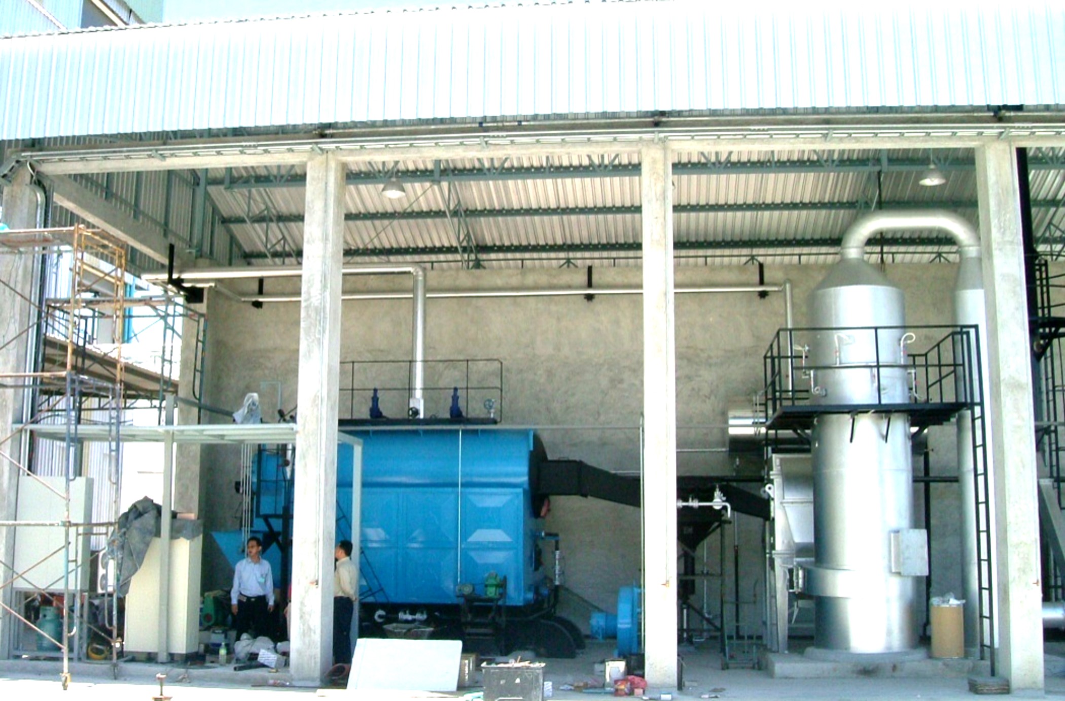
Once the boiler is offline, the work is far from over. In practice, this phase is where a lot of plants cut corners — and pay for it six months later with unexpected tube failures, pitting damage, or a failed pressure-vessel inspection that delays restart by days.
Cooling Period and Safe Entry Requirements
Before anyone opens a manhole or climbs into a drum, two conditions must both be satisfied: the internal pressure must have fully returned to atmospheric, and the drum shell metal temperature must be below 50°C. That second condition catches people out more than the first. A unit that has been vented to atmosphere can still have drum walls sitting at 80–100°C for hours afterward, and entry at that temperature is both a burn hazard and a risk of introducing a cold-water slug that causes localized thermal shock.
For low- to medium-pressure units in the 1.0–1.6 MPa range, natural cooling to that threshold typically takes 24–36 hours from the moment fire is extinguished, assuming no forced ventilation. High-pressure units — anything at 9.8 MPa and above — routinely need 48–72 hours, and rushing that window by cracking open inspection ports or forcing airflow through the gas path is not a shortcut worth taking. The mass of metal in a large steam drum at those pressures retains heat far longer than operators expect.
Internal Inspection Scope
Waterwall tube inspection is the first priority once entry is safe. Look for visible scale buildup on the waterside surface — anything over roughly 0.5 mm of dense calcium/silica scale is worth documenting and usually indicates a water-treatment issue that needs resolving before the next run. Pitting on tube inner surfaces, particularly in the lower headers where oxygen concentration can spike during idle periods, is an early sign of oxygen corrosion that progresses faster than most people expect. Hydrogen damage — a brittleness mode caused by acid corrosion under scale deposits — won’t always be visible; a tube that looks fine can be metallurgically compromised, which is exactly why chemical cleaning intervals matter.
On the fireside, superheater tubes deserve close attention for external corrosion (sulfidation and vanadium attack in high-sulfur coal environments) and for ash bridging between tube rows that can mask hot spots. In CFB boilers specifically, the cyclone body, the downcomer, and the return leg refractory need systematic tapping and visual checks for spalling and cracking. Refractory damage in those zones is common after aggressive load cycling and, if ignored, leads to hot-spot erosion of the casing steel behind it.
Short-Term Preservation (Layup Under 30 Days)
Dry layup is often unnecessary for outages under a month. The practical choice is either a nitrogen blanket — maintaining drum pressure at 0.05–0.1 MPa with nitrogen to exclude oxygen ingress — or wet layup with demineralized water dosed to pH 10.5–11 using ammonia or morpholine. Wet layup works well in mild climates where freeze risk is low. In colder regions, or where the boiler room is unheated, nitrogen blanket is safer and avoids the risk of freeze damage to economizer tubes.
A nitrogen blanket at 0.05–0.1 MPa effectively prevents oxygen-induced pitting during short-term boiler layup.True
Maintaining a positive inert-gas pressure in the steam drum and headers prevents atmospheric oxygen from entering the waterside circuit, which is the primary driver of corrosion pitting during idle periods — this is standard practice per ASME and industry operating guidelines.
Long-Term Preservation (Layup Over 30 Days)
For extended outages, the approach shifts entirely. The system needs to be fully drained, then dried — either by low-temperature forced warm air or by allowing residual heat to drive out moisture before the system cools completely. Silica gel canisters placed in headers and drums absorb residual moisture, and in larger units nitrogen filling of the waterside is the more reliable method. Monthly checks of internal moisture and oxygen levels are not optional; they are the only way to catch preservation failure before pitting becomes measurable tube-wall loss.
Economizer and air preheater fin surfaces on the gas side need attention too. Sulfuric acid condensate from coal combustion gases can sit on fin surfaces during extended cold layup and cause aggressive dew-point corrosion. Applying a thin coat of preservation oil or an appropriate anti-corrosion coating to exposed carbon-steel fin surfaces is cheap insurance relative to the cost of replacing fouled or corroded preheater modules.
Return-to-Service Pre-Qualification
Before re-lighting, the full pre-startup checklist needs to be re-run from scratch — not just spot-checked. Every maintenance work order completed during the outage should be closed out and reviewed: valve replacements, tube repairs, refractory patching, instrument calibrations. It is surprisingly common for a repaired isolation valve to be left in the wrong position or for a newly replaced pressure transmitter to be wired with incorrect scaling.
The final gate is sign-off from the authorized pressure-vessel inspector or boiler inspection body, as required by local regulations. In most jurisdictions, any internal inspection following a shutdown constitutes a formal re-commissioning event for the pressure vessel record. Skipping that sign-off is not just a regulatory violation — it also voids most insurance coverage for the unit. Get the stamp, file the paperwork, then light the fire.
Common Operator Errors During Startup and Shutdown and How to Prevent Them
Every procedure manual looks clean on paper. The plant floor is different — production pressure is real, shortcuts feel minor in the moment, and the consequences often arrive weeks or months later in the form of a cracked drum nozzle or an unplanned outage that nobody can easily trace back to a single bad decision. These five errors show up repeatedly across coal-fired boiler installations, regardless of boiler size or operator experience level.
Rushing the Warm-Up Curve
This is probably the single most common mistake, and it’s almost always driven by a shift supervisor getting a call from the production floor. The standard pressure rise rate limit of 0.1–0.15 MPa per 10 minutes exists specifically because drum shell metal and internal nozzle welds cannot equalize temperature instantaneously. When operators skip the intermediate pressure holds — typically at around 0.1–0.2 MPa and again near 50–60% of working pressure — the thermal gradient across the drum shell can exceed 50°C, sometimes significantly. That gradient cycling, repeated over dozens of startups, initiates fatigue cracking at nozzle-to-drum welds long before any visual sign appears. By the time an ultrasonic inspection finds it, the repair cost and lost production time dwarf whatever was “saved” by the faster startup.
The fix is procedurally locking the hold points in the DCS startup wizard so they cannot be manually overridden without a supervisor authorization code. Soft interlocks that flag violations are not enough — operators learn to dismiss them.
Wrong Fan Sequencing on Shutdown
Stopping the FD (forced draft) fan before the ID (induced draft) fan reversal is a textbook error, yet it still happens, usually when an operator is manually stepping through shutdown under time pressure or following a partial power event. The result is momentary positive furnace pressure, which pushes hot flue gas and glowing embers back through any leakage path into the boiler room. CO alarms are the best-case outcome. Refractory damage or a fire in the ash handling ductwork is the worst case. Correct sequence: reduce fuel feed first, maintain negative draft throughout, stop FD fan only after ID fan is confirmed running and furnace pressure is stable negative.
Neglecting Continuous Blowdown During Early Startup
During the low-flow, pre-steam phase of a cold startup, evaporation is already concentrating dissolved solids in the boiler water, but feedwater flow is minimal and blowdown is often forgotten entirely. TDS can spike to levels that would trigger an automatic blowdown alarm under normal operation. The deposit goes straight onto high-heat-flux waterwall tubes where it causes localized overheating. Scale as thin as 0.5–1 mm on the fire side of a waterwall tube meaningfully increases tube wall temperature — enough to accelerate oxidation on higher-pressure units. Running continuous blowdown from the first moment steam begins to form is not optional; it should be a checklist-enforced step, not left to operator judgment.
CFB Coal Injection Before Bed Temperature Is Ready
On circulating fluidized bed units, introducing coal into a bed that hasn’t reached 600°C — some designs require 650°C or higher before primary fuel injection — results in raw coal accumulating in the bed without igniting. When bed temperature eventually climbs, that accumulated coal can ignite suddenly, causing a rapid pressure spike and, in poorly maintained units with compromised expansion joints or ductwork, a deflagration event.
Introducing coal into a CFB bed below the minimum ignition threshold (typically 600–650°C depending on coal rank and bed material) is a recognized cause of furnace explosion incidents in industrial CFB boilers.True
This is consistent with CFB combustion engineering fundamentals and is documented in boiler safety standards including GB/T and relevant ASME operating guidelines. The ignition threshold varies with coal volatile content and bed inert material ratio, but the risk of unburned fuel accumulation below threshold temperature is well established.
Bed temperature interlock — a hard cutoff on coal feeder start permission — should be commissioned and tested at FAT. Never accept a boiler where this interlock can be manually defeated at the local panel without a logged override.
Bypassing LOTO During ‘Quick’ Inspection Stops
The reasoning is always the same: “We’re only going to look, we’re not doing any work.” LOTO (lockout/tagout) injuries in boiler rooms nearly always involve that logic. Residual steam pressure, hot condensate in drain lines, and rotating ID/FD fan impellers that are coasting down all remain hazards for far longer than operators expect. A planned shutdown for inspection is not meaningfully different from a maintenance shutdown in terms of required isolation discipline.
Prevention at the System Level
Individual operator training helps, but it degrades over time and doesn’t survive staff turnover. The measures that hold are structural: DCS startup and shutdown wizards with sequence-enforced step completion, operator certification requirements tied to specific boiler ratings, and third-party procedure audits every 12–24 months. For EPC project sites, Taisan Group’s standard factory acceptance test protocol includes a full operator walkthrough of both startup and emergency shutdown sequences on the actual commissioned unit before handover — not a simulator, not a classroom. In practice, that single session catches more procedural gaps than months of classroom training.

Startup and Shutdown Procedures Specific to CFB, Chain-Grate Stoker, and Pulverized Coal Boiler Types
The three boiler types share the same working fluid and the same general pressure-part physics, but their combustion systems are fundamentally different machines. Applying a chain-grate startup protocol to a CFB unit — or worse, running a pulverized coal mill without the correct seal-air sequence — creates failure modes that the other types simply don’t have. Field incidents almost always trace back to operators cross-applying procedures they learned on a different furnace configuration.
Chain-Grate Stoker Boilers
Grate speed is the first thing to get right, and most operators set it too fast during initial coal bed formation. During cold startup, grate speed should be held at roughly 10–20% of rated travel speed, slow enough to build a thick, evenly distributed coal bed — typically 150–200 mm — before furnace temperature climbs. Running the grate too fast in early startup thins the bed, produces localized burnout zones, and warps grate bars within a few hundred hours. Once ignition is confirmed and bed temperature is stable, grate speed increases in proportion to load, not on a fixed timer.
The coal gate opening sequence matters more than most operators appreciate. The front coal gate sets the bed depth; it should be cracked open first and adjusted based on visual inspection through the fire door, not set to a pre-programmed position and forgotten. Different coal sizes — and coal delivered in winter tends to have higher moisture, which changes how it beds — require manual judgment at this stage, at least until the operator has accumulated enough run hours on that specific fuel source.
During shutdown, sealing the ash pit is a step that gets skipped more often than it should. If the ash pit dampers are left open, natural convection pulls cold air up through the grate after fire is killed, which creates an asymmetric cooling gradient across the grate segments and accelerates warping. Close the ash pit doors and reduce the induced draft fan to minimum before killing fuel feed.
CFB Boilers
CFB units in the industrial and small power range typically run 35–480 t/h steam output, and their startup requirements are more involved than either stoker or PC boilers. Before any fuel enters the system, the cold-air distribution plate pressure drop test must be completed — this confirms the air cap nozzles are unblocked and airflow distribution is uniform across the bed cross-section. A blocked nozzle that goes undetected will cause a dead zone in the bed, leading to defluidization and potentially a clinker formation that requires a full bed drain to clear.
Fluidization velocity verification follows: furnace air velocity should reach 4–6 m/s before bed temperature is brought up, confirmed by both the air flow instrumentation and — on units equipped with it — bed pressure differential readings across the furnace height. Bed inventory management during startup requires maintaining the correct sand/ash inventory mass; too little inventory and you can’t sustain stable fluidization, too much and you starve the fans.
The hot bed drain procedure is unique to CFB and is essentially a controlled emergency — when shutdown must happen immediately and the bed is still at operating temperature (typically 850–950 °C), the bed material is drained through the bottom drain valves into refractory-lined hoppers. This protects the distribution plate and lower furnace refractory from thermal damage that would otherwise occur if superheated bed material sat static against those surfaces.
Pulverized Coal Boilers
The mill startup sequence is non-negotiable and has a specific order for one reason: coal dust explosion prevention. Seal air must be established before primary air is introduced, and primary air must be running and confirmed before coal feed starts. Seal air pressurizes the mill bearing labyrinth seals and classifier shaft seals, preventing coal dust from migrating into bearing housings where it can smolder. Skipping or reversing this sequence has caused mill fires in practice — it’s not a theoretical risk.
Fireball stabilization before load increase is the other area where operators cut corners. The furnace flame pattern should be visually stable and O₂ readings at the economizer outlet should be trending steadily before any increase in coal feed rate. Attempting to ramp load while the flame is still establishing leads to incomplete combustion pulses that deposit unburned carbon in the back-pass and create CO excursions that can trip pollution monitoring systems.
During shutdown, each mill must be isolated and purged individually — typically with hot air — to evacuate residual coal dust from the classifier and mill bowl before the unit cools. Mills left with coal dust residue, especially in humid climates or after prolonged outages, are a documented ignition source on the next startup.
Key Startup Parameter Comparison
| Parameter | Chain-Grate Stoker | CFB | Pulverized Coal |
|---|---|---|---|
| Ignition method | Oil/gas auxiliary burner or manual ignition coal | Oil/gas start-up burner + bed preheating | Oil/gas igniter, then coal |
| Minimum stable load | ~25–35% of rated | ~30–40% of rated (fluidization limit) | ~25–30% of rated (flame stability limit) |
| Cold warm-up duration | 3–5 hours (capacity and coal moisture dependent) | 5–8 hours (bed heat-up rate limiting) | 4–7 hours (refractory and drum temperature dependent) |
| Shutdown cooling rate | Controlled grate clearance over 2–4 hours | Bed drain required above ~800 °C bed temp | Mill purge mandatory; furnace natural cool-down |
CFB boilers require a distribution plate pressure drop test before each cold startup to verify air cap integrity.True
Blocked air cap nozzles in a CFB distribution plate cause uneven fluidization, localized defluidization, and potential clinker formation in the bed. The pressure drop test — comparing measured ΔP across the plate against the design specification — is a standard pre-startup check on CFB units and is specified in most OEM operating manuals.
How Boiler Type Affects DCS Configuration in EPC Projects
In EPC projects, our engineering team programs DCS startup interlocks and HMI guidance screens differently for each boiler type — not just different setpoints, but different logic structures. A CFB unit gets a fluidization interlock that prevents fuel feed if air velocity is below threshold; a PC boiler gets a mill seal-air pressure permissive that gates primary air activation; a chain-grate unit gets a grate speed limiter that prevents fast-ramp during the first 45 minutes of cold startup. Operators working across multiple boiler types at the same plant are particularly prone to error, and clearly differentiated HMI screen layouts — color-coded by boiler type in some installations — reduce that risk measurably. Generic DCS templates applied across all three types are a known source of procedural accidents during commissioning.
Frequently Asked Questions About Coal-Fired Boiler Startup and Shutdown
How long does a cold startup take for an industrial coal-fired boiler?
The honest answer: it depends on what you’re starting, and what temperature the drum wall is sitting at when you begin. For chain-grate stoker units in the 10–35 t/h range, a proper cold startup typically runs 4–8 hours from initial fire to stable, on-spec steam supply. Larger CFB units above 75 t/h generally need 6–10 hours, sometimes nudging toward 12 hours in winter when the refractory and drum metal are genuinely cold-soaked.
The governing constraint is the drum wall temperature gradient, not a timer on the wall. Pressure rise rate should stay within roughly 0.1–0.15 MPa per 10 minutes to keep thermal stress across the drum shell and header welds within safe limits. Push faster than that and you’re accumulating low-cycle fatigue damage that won’t show up as a failure today — it shows up two or three years from now as a hairline crack in a drum nozzle weld that puts the unit offline for weeks. Experienced operators learn to read drum expansion behavior and watch for uneven heating across the furnace width, especially on wide chain-grate units where side-to-side temperature imbalance is common.
Can I speed up shutdown by spraying cold water into the drum?
No. Full stop. Rapid quenching creates a steep thermal gradient across the drum shell that can exceed material yield limits in under a minute. The result is stress corrosion cracking, warped tube ligaments, and — depending on your jurisdiction — an immediate void of the pressure vessel inspection certificate. Insurance claims following this kind of incident are rarely straightforward.
Injecting cold water into a hot boiler drum during shutdown to accelerate cooling is a recognized cause of stress corrosion cracking and pressure-vessel certificate invalidation.True
Rapid thermal quenching induces thermal shock stresses that exceed the yield strength of drum shell material, causing cracking. Regulatory pressure vessel codes in most jurisdictions require controlled cooling rates and prohibit emergency cold-water injection as a cooling method.
The only permissible approaches are controlled natural cooling or approved slow blowdown per your boiler manufacturer’s procedures. For units operating at 1.6 MPa, natural cooling to ambient typically takes 24–48 hours before it’s safe to open a manhole. High-pressure units at 9.8 MPa or above need 48–72 hours, sometimes longer depending on insulation thickness and ambient conditions.
What drum water level should I maintain during shutdown?
Keep the level at the normal working range — roughly mid-gauge glass — until steam pressure drops below about 0.5 MPa. Below that threshold, allow the level to settle toward the low working level mark. The reason: maintaining a high water level in a cooling drum promotes thermal siphon circulation, which can cause localized reheating of water-wall tubes and uneven cooling in the lower drum. It’s a subtle effect, but on units with long, horizontal drum sections it’s worth managing deliberately.
How often should safety valves be tested during startup?
Perform a manual lift test at roughly 75% of set pressure during each cold startup once pressure has stabilized and the boiler is holding steady — not while pressure is still climbing. This confirms the valve spindle isn’t stuck from scale or corrosion that built up during the outage. Full-lift automatic tests follow local regulatory inspection schedules, which in most markets means annual third-party verification. Don’t skip the manual check on the assumption that the annual test was recent; a valve can seize in a matter of weeks if the unit sat idle with wet steam condensate sitting on the seat.
What is the correct fan trip sequence during an emergency shutdown?
Sequence matters here and getting it wrong risks either a furnace pressure excursion or a fuel-rich puff ignition.
Stop the coal feeder first. Trip the FD (forced draft) fan next. Keep the ID (induced draft) fan running for approximately 5 minutes to complete the post-purge cycle — this clears unburned combustibles from the furnace and flue gas path. Only then trip the ID fan. This sequence maintains negative furnace pressure throughout the event, which is what keeps hot gas and flame from pushing back through inspection ports or ash handling joints. On DCS-controlled units, this sequence should be hard-coded as an interlocked trip logic, not left to operator memory under stress.
Does Taisan Group provide operator training for startup and shutdown procedures as part of an EPC boiler project?
Yes. Taisan Group’s EPC scope covers on-site commissioning supervision, DCS interlock configuration specific to the installed unit, and formal operator certification training structured to satisfy local regulatory requirements — whether that’s a country-specific boiler operator license or a site-level competency sign-off required by the plant owner. In practice, commissioning engineers stay on-site through the first full startup cycle and at least one planned shutdown, working alongside the local operating crew rather than just handing over a manual. For export projects where operators have limited prior experience with CFB or high-pressure stoker units, that hands-on transfer period is worth more than any document package.
References
Annual Reminder for Restart of Boilers — Startup Checks and Normal Starting Sequence — National Board of Boiler and Pressure Vessel Inspectors
Recommendations for a Safe Boiler Room — Startup and Shutdown Checklist Guidance — National Board of Boiler and Pressure Vessel Inspectors
ASME/API Boilers and Fired Pressure Equipment Operation and Maintenance — ASME
Consensus on Operating Practices for Feedwater and Boiler Water Chemistry — ASME
Coal-Fired Power Plant Boiler Solutions — Combustion and Boiler Control — Emerson
Coal Analysis and Production Information — Thermo Fisher Scientific
Boiler Efficiency and Combustion — Fuel, Air and Combustion Principles — Spirax Sarco
Boilers and Fired Pressure Equipment — Inspection, Repairs and Alterations — ASME
What Are the Correct Startup and Shutdown Procedures for Industrial Coal-Fired Boilers? Read More »