
How to Inspect Coal-Fired Boiler Tubes and Drums Using NDT Methods?
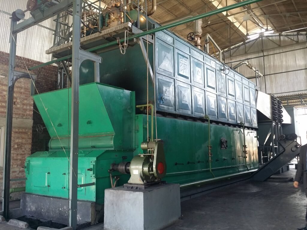
A tube failure on a coal-fired boiler rarely announces itself. One shift it’s a hairline crack buried under scale; the next it’s an unplanned outage that pulls the whole unit down for anywhere from three days to three weeks depending on how bad the damage is and whether you have spares on the shelf. The repair bill is one thing — replacement superheater or waterwall tubes, welding labour, post-weld heat treatment — but the lost generation or process steam revenue is usually the number that keeps plant managers awake. Corrosion and erosion alone account for roughly 35% of tube failures in coal-fired units, with fatigue cracking and creep failures making up most of the rest. Catching these before they breach is exactly what a structured NDT programme does.
Inspecting coal-fired boiler tubes and drums with NDT methods means applying a combination of ultrasonic testing (UT), radiographic testing (RT), magnetic particle inspection (MPI), and visual examination at defined intervals — targeted at the highest-risk zones first: waterwall panels, superheater and reheater tube banks, economiser sections, and drum welds. UT can resolve wall-thickness loss down to about 0.1 mm and flag internal flaws from roughly 1–2 mm diameter in carbon steel. Any tube measuring below 80% of its nominal wall thickness (per ASME PCC-2 and API 579 fitness-for-service criteria) should be flagged for replacement or engineering review before the unit returns to service.
What most inspection programmes get wrong isn’t the method — it’s the sequencing. Plants tend to UT every tube on a grid pattern and declare success, meanwhile the real damage is happening in a 200 mm section just downstream of a flow-deflecting baffle where nobody thought to look. Understanding why each failure mode concentrates where it does changes how you deploy your instruments, your crawler, and your inspector’s time. That’s what the rest of this guide works through.
Mapping the Critical Inspection Zones on Coal-Fired Boiler Tubes and Drums
Before any NDT crew sets foot on the plant floor, someone needs to decide where to look. Boilers are large, access is limited, and inspection windows are short. Spending half your outage doing wall-thickness scans on mid-elevation waterwalls that have run fine for twelve years, while missing the return bends on the pendant superheater, is a real pattern — and it shows up in failure reports with uncomfortable regularity.
The failure-mode breakdown matters here: corrosion and erosion account for roughly 35% of coal-fired tube failures, fatigue cracking around 25%, overheating and creep near 20%, and weld defects perhaps 15%. That distribution is not uniform across the boiler. It clusters hard.
Waterwall Tubes
The lower furnace is where the chemistry turns hostile. In the reducing atmosphere near burner openings — especially on wall-fired and corner-fired units running high-sulfur coal — sulfidation corrosion can eat through carbon steel waterwall tubes at rates between 0.3 and 1.2 mm per year, depending on local stoichiometry, coal sulfur content, and how aggressively operators trim excess air. Hydrogen damage from atomic hydrogen migration is less obvious; it leaves no external trace but causes blistering and step-cracking detectable only with angled-beam UT or phased-array scans. The slag line, where partially fused ash adheres and re-melts cyclically, drives both erosion and under-deposit corrosion. Inspect from roughly 1 m below the primary burner elevation up to 1.5 m above it. That band typically shows the worst metal loss.
Superheater and Reheater Tubes
Fly-ash erosion hits hardest on the leading-edge (gas-facing) side of pendant loops and the outer radius of return bends. In service, these bends also run hotter than the straight sections — sometimes 15–30 °C higher depending on flow distribution — and at operating temperatures above roughly 520 °C in alloy steels like T22 or T91, creep cavitation starts accumulating in grain boundaries long before any dimensional change appears. Phased-array UT on return bends and replication metallography on accessible bends are not optional on units running above 10,000 hours since the last inspection. External OD oxide scale on high-temperature superheater tubes can mask erosion; don’t let scale thickness fool a manual UT reading.
Economizer Tubes
Cold-end corrosion from acid dew-point condensation — primarily sulfuric acid when flue-gas temperature drops below roughly 130–160 °C depending on sulfur content and moisture — concentrates on the last two to four rows at the flue-gas exit. Tube surfaces facing the gas flow erode from high-velocity ash; surfaces on the leeward side collect acid condensate. The waterside story is different: oxygen pitting forms during startup and shutdown when dissolved oxygen is poorly controlled, and it typically appears as sharp-edged hemispherical pits on the tube ID near inlet headers.
Convection Bank and Screen Tubes
Gas-lane edges are where erosion channels form — narrow corridors between adjacent tube rows where ash velocity spikes due to uneven flow distribution. The damage pattern is localized but deep, sometimes cutting 40–60% through wall thickness before anyone notices. Soot-blower erosion is a different signature: a narrow, often crescent-shaped groove at a fixed angular position, repeatable from one tube to the next at the same elevation, corresponding to the blower lance arc. It is easy to recognize once you have seen it once.
Steam Drum
The highest-risk locations are the weld heat-affected zones at downcomer and riser nozzle connections — residual stress concentrations that SCC and fatigue attack preferentially — and the waterline band on the drum ID, where differential concentration and wetting-drying cycles drive concentration-cell corrosion. Drum ends under insulation are routinely neglected; CUI here is slow but continuous, and the geometry makes TOFD or phased-array UT the only practical method without full insulation removal.
Mud Drum and Headers
Sediment settles at the bottom of mud drums. That settled layer traps corrosive species and sits against metal that may not have been properly blowdown-managed. Pitting here can be deep before it is found. Headers sitting in humid environments — common in outdoor or semi-outdoor boiler houses — develop CUI under lagging, particularly at support saddles and at any point where the insulation jacket has been breached or poorly sealed.
Zoning for Inspection Priority
A practical way to allocate outage time is a three-tier system:
| Tier | Frequency | Zone | Key Variables |
|---|---|---|---|
| 1 — Annual | Every planned outage | Lower waterwall burner zone, superheater return bends, steam drum nozzle welds, cold-end economizer | Fuel sulfur >1%, operating pressure >10 MPa, unit age >8 years |
| 2 — Periodic | Every 2–3 years | Mid-furnace waterwalls, convection bank gas-lane edges, soot-blower positions, mud drum bottom | Moderate erosion history, stable operation |
| 3 — Major overhaul | Every 5–6 years or at full refractory outage | Drum end-plate zones, header CUI, full superheater OD scale mapping, reheater leading-edge survey | Units with no prior baseline data move to Tier 2 immediately |
Fuel sulfur content, operating pressure, and accumulated run-hours since last inspection should all shift zones upward if thresholds are exceeded. A unit running high-sulfur lignite at elevated pressure and carrying 15,000 hours since the last thorough inspection has no Tier 3 zones — everything is Tier 1.
Remaining wall thickness below 80% of nominal is the threshold for mandatory remedial action under ASME PCC-2 and API 579 fitness-for-service assessments.True
ASME PCC-2 and API 579 both establish fitness-for-service criteria that treat 80% of nominal wall thickness as a key threshold below which continued service requires formal engineering evaluation or replacement, reflecting the margin needed against burst pressure at design conditions.
Ultrasonic Testing (UT) Methods for Tube Wall Thickness and Flaw Detection
UT is the workhorse of boiler inspection — not because it’s glamorous, but because it works reliably on the geometries and material conditions you actually encounter in a coal-fired plant. Corroded tube bores, scale-loaded surfaces, thick drum shells with complex nozzle welds — UT handles all of it, provided you match the technique to the problem.
Pulse-Echo A-Scan for Wall Thickness Measurement
For routine thickness surveys on carbon steel waterwall and superheater tubes, 5–10 MHz single-crystal probes are standard. The higher end of that range (closer to 10 MHz) gives better resolution on thin tubes — say, 3–6 mm nominal wall — but it loses penetration quickly if there’s scale buildup or rough internal surfaces, which is common in boilers running harder coals or with inconsistent water treatment. In those cases, dual-element (pitch-catch) transducers are worth the extra setup time. They’re less sensitive to near-surface dead zones and handle pitted or scaled inner walls far better than single-crystal probes.
Couplant matters more than most technicians admit. Glycerin works well on vertical tube runs; ultrasonic gel is fine on horizontal surfaces. Don’t let anyone use machine oil as a couplant shortcut on hot tubes — at surface temperatures above roughly 50–60 °C, standard gels degrade fast and you’ll get erratic readings. High-temperature couplants exist for surfaces up to around 200 °C if you need them.
Calibration must reference a step-wedge block in the same base material and heat treatment as the tubes being tested, per ASME Section V Article 4. Using a generic carbon steel block for a Cr-Mo alloy superheater tube is asking for a systematic error. The sound velocity difference between P22 (2.25Cr-1Mo) and plain carbon steel is small but not negligible when you’re chasing a 0.3 mm wall-loss call.
Phased-Array UT for Drum Nozzle and Header Welds
PAUT earns its cost premium on thick-wall drum welds — shell thicknesses of 40–80 mm are common on medium-to-high-pressure industrial boilers in the 10–25 MPa range. A conventional multi-angle radiography campaign on a drum with 20+ nozzle welds can take days, requires radiation exclusion zones, and still struggles to size embedded planar flaws accurately. PAUT with a properly programmed focal law set — typically sweeping from roughly 40° to 70° shear wave, with index points stepped to cover the full weld volume — cuts that scanning time by somewhere in the 40–60% range depending on drum geometry and access.
The focal law setup is where mistakes get made in practice. If the wedge angle isn’t correctly matched to the pipe OD or the focal depth isn’t optimized for the expected flaw depth zone, you can have blind spots right in the heat-affected zone. Review the scan plan before mobilization, not on-site.
Automated UT Crawlers for Convection Pass Tube Runs
Long runs of convection-pass tubes — often 8–15 meters of straight or gently curved tubing — are tedious and inconsistent with manual scanning. Magnetic-wheel AUT crawlers solve the consistency problem. A well-set-up crawler system acquires data at up to roughly 150 mm/s and outputs a C-scan map that immediately shows thickness contours along the tube length.
The real value is trending. Compare C-scan maps from successive outages and you can see erosion or corrosion progressing before it reaches a critical threshold. That’s the difference between a planned tube replacement during a scheduled shutdown and a weekend emergency with half the convection bank down.
TOFD for Drum Shell Weld Volumetric Sizing
Time-of-flight diffraction is the method of choice when you need precise through-wall flaw sizing on drum longitudinal and circumferential seam welds. Sizing accuracy runs around ±0.5 mm for through-wall extent — meaningfully better than conventional pulse-echo for planar flaws — which matters when you’re doing a fitness-for-service assessment and need to demonstrate remaining ligament adequacy. ASME VIII Div. 1 Appendix 12 provides the code path for TOFD acceptance; in practice, TOFD and PAUT are often run together, with TOFD handling sizing and PAUT handling detection and lateral positioning.
Guided-Wave UT for Insulated Headers and Buried Sections
GWUT is a screening tool, not a sizing tool — keep that distinction clear. A single probe ring on an insulated header can screen up to roughly 20–30 m of pipe in both directions from that location, flagging zones of cross-sectional area loss above a set threshold. It won’t tell you wall thickness to 0.1 mm. What it does is tell you which 0.5-meter sections actually need insulation stripped and conventional UT performed, which on a large boiler building with dozens of insulated header runs can save several days of insulation removal.
Guided-wave UT can screen up to 30 meters of pipe length from a single transducer ring locationTrue
Published GWUT system specifications from major vendors (Olympus, Eddyfi/WAPMS) and peer-reviewed NDT literature consistently cite effective inspection ranges of 15–30 m depending on pipe diameter, coating condition, and frequency selection. This is consistent with field application data in the power generation industry.
Acceptance Criteria and Retirement Decisions
The 80% remaining-wall rule from ASME PCC-2 Article 4 is the standard starting point: if measured wall is below 80% of the nominal design thickness, that tube section is a retirement candidate. But that’s a minimum floor, not a complete engineering decision. For tubes operating near creep range — superheater and reheater tubes above roughly 450–500 °C depending on material — a Level 2 fitness-for-service assessment per API 579-1/ASME FFS-1 is warranted even if you’re still above the 80% threshold, because creep damage doesn’t always show up as simple wall loss.
Documentation and CMMS Integration
Every UT campaign should produce digital thickness maps with defect coordinates referenced to fixed weld seam datums — not just a table of minimum readings. When you reference a flaw to “250 mm from nozzle N7 centerline, 180° orientation,” your maintenance team can find it at the next outage without re-scanning the entire zone. Feed that data into your CMMS with the inspection date, operator qualification, instrument serial number, and calibration record. Boiler tube inspection history has real value in remaining-life calculations — but only if the data is actually retrievable five years later.
Radiographic Testing (RT) and Digital Radiography (DR) for Weld and Internal Defect Inspection
UT is the workhorse for wall thickness surveys, but it has a real limitation that any experienced inspector will tell you about: volumetric defects — slag inclusions, porosity clusters, incomplete fusion voids — sitting inside a weld cap on a small-diameter tube simply don’t produce a reliable UT signal when you can’t get adequate probe contact or beam angle. That’s where RT earns its place.
When RT Outperforms UT on Boiler Components
For circumferential butt welds on tubes below roughly 25 mm OD — waterwall stubs, superheater elements, economizer coils — the tube curvature makes shear-wave UT awkward at best. A 2 mm porosity cluster or a slag stringer running along the weld root can sit completely in the UT beam’s dead zone. Film or digital radiography sees those volumetric features clearly because the attenuation difference shows up regardless of surface geometry.
Drum nozzle-to-shell welds are another case. The geometry — a curved nozzle intersecting a thick cylindrical shell, often with a reinforcing pad on top — creates too many beam-path complications for contact UT to cover the full weld volume reliably. RT with a panoramic or single-wall exposure cuts through that complexity. Erosion-thinning patterns around nozzle bores are also easier to interpret from a radiograph than from a grid of UT A-scan readings.
Film RT Procedure for Carbon Steel Tube Butt Welds
For SA-210 Grade A-1 or C tubes in the 3–8 mm wall thickness range — typical waterwall and economizer stock — the standard approach under ASME Section V Article 2 uses wire-type IQIs per SE-747 or ASTM E747. Essential wire diameter selection depends on weld thickness: at 6 mm wall you’re targeting a 2% sensitivity, which usually means a 0.16–0.20 mm essential wire. Source-to-film distance (SFD) needs to satisfy the geometric unsharpness limit, Ug ≤ 0.51 mm per ASME, which at typical Ir-192 focal-spot sizes means keeping SFD at roughly 400–700 mm depending on tube-to-film distance. Exposure times vary considerably with source activity — a fresh 100 Ci Ir-192 source at 500 mm will expose D7 film through a 6 mm weld in somewhere between 1 and 4 minutes; a depleted source late in its half-life cycle will run much longer and slow your outage schedule noticeably.
Computed Radiography (CR) in Confined Furnace Spaces
Phosphor imaging plates changed the practical side of boiler inspection more than most people acknowledge. A furnace cavity barely wide enough for one person with a harness is no place to be wrestling film cassettes, mixing chemicals, and worrying about film fogging from residual heat. CR plates are flexible, reusable across roughly 1,000–3,000 cycles depending on handling and storage conditions, and the resulting digital image archives cleanly for comparison across outage cycles. Weld-by-weld trend data over three or four shutdowns is genuinely useful for identifying chronic fabrication issues or localized corrosion acceleration.
Spatial resolution with CR is slightly lower than fine-grain film — typically 3–5 lp/mm versus 8–12 lp/mm for D4 film — which matters for very thin-wall tubes under 3 mm. For typical boiler tube dimensions, it’s usually not a limiting factor.
Digital Detector Arrays and Real-Time DR
DDA systems (flat-panel detectors, also called direct digital radiography or DR) push acquisition speed to 60–80% faster than film for production weld inspection. On a tube fabrication line or during a major tube replacement, that matters enormously. Geometric unsharpness control requires careful source-to-detector distance management and is governed by ASTM E2698 for digital image acceptance criteria.
Digital radiography produces images with diagnostic quality equivalent to film for most boiler tube weld applications when ASTM E2698 procedures are followedTrue
ASTM E2698 and ASME Section V Article 2 Mandatory Appendix VIII establish acceptance criteria for digital radiographic images that have been validated against film-based benchmarks in industrial qualification studies; DDA systems meeting these criteria are accepted by most AHJs for Code work
The real workflow advantage is that a PAUT or TOFD team can follow immediately behind RT screening — RT identifies suspect weld locations, PAUT characterizes and sizes the indications for fitness-for-service decisions under API 579. Trying to satisfy both ASME Section I volumetric inspection requirements and a jurisdictional AHJ’s sizing demands with a single method is rarely practical. Using RT as the screening pass and TOFD or PAUT for disposition is cleaner, faster, and easier to document.
Radiation Safety in Boiler Furnace Environments
Working inside a boiler furnace with an Ir-192 or Se-75 source introduces confined-space radiation hazards that go beyond a normal open-field RT job. Se-75 has lower gamma energy (roughly 0.1–0.4 MeV) than Ir-192 (0.3–0.6 MeV average), which reduces shielding requirements and scatter in tight spaces — a real advantage inside a furnace with parallel tube banks on all sides. Shielding calculations need to account for backscatter off tube banks and refractory walls, which can increase dose rates unpredictably.
Controlled-area barriers, written radiation permits with source identification and exposure parameters, continuous dosimetry, and a dedicated radiographer’s assistant with direct line-of-sight to the exclusion boundary are baseline requirements. Confined-space entry permits and radiation work permits need to be co-issued and managed together. In practice, the bottleneck is often the permit coordination rather than the actual radiography.
Dissimilar-metal welds between austenitic superheater tubes (TP321, TP347) and ferritic alloy headers (P22, P91) need technique adjustment because the density difference between austenitic and ferritic material shifts the optimum exposure parameters. Dual IQI placement — one on each material — is the reliable approach rather than relying on a single IQI placed on the higher-density side.
Magnetic Particle Testing (MT) and Dye Penetrant Testing (PT) for Surface and Near-Surface Cracks
Surface-breaking cracks kill boilers quietly. A tight stress-corrosion crack on a drum nozzle weld can sit undetected through multiple UT scans — UT is excellent at wall thickness and volumetric flaws, but it will miss a 0.3 mm wide, 4 mm deep surface crack if the beam geometry isn’t right. That’s where MT and PT earn their place in the inspection sequence.
When MT Is Mandatory vs. When You Can Weigh the Options
ASME Section I requires MT or PT on all pressure-part welds during fabrication — this is not optional, not a “best practice,” it is a code requirement with no carve-outs. In field inspection of operating coal-fired boilers, MT becomes effectively mandatory on drum nozzle welds, manway flange faces, and suspension lug attachment welds. These locations see bending stress, thermal cycling, and sometimes corrosion-fatigue in combination. If you skip MT on a manway flange face because it “looked fine visually,” you are accepting a risk that the code framers specifically tried to prevent.
Suspension lug welds deserve particular attention in coal-fired plants with large steam drums — these can run 1,200 mm to 2,400 mm shell diameter, and the hanger loads combined with start-stop thermal cycling create a fatigue environment that plain visual inspection simply cannot assess.
Wet Fluorescent MT on Drum Shell Welds — Technique Matters
For drum shell welds, wet fluorescent magnetic particle inspection (WFMPI) using an AC yoke is the right choice for detecting fine stress-corrosion cracks. The AC yoke produces a skin-effect field that concentrates flux at the surface, which is exactly what you want for surface-breaking defects. Dry powder methods are faster and cheaper, but in practice they miss tight, oxide-filled cracks because the particle mobility is lower and contrast under white light is poor compared with fluorescent particles under UV. On a drum that’s been in service for 8–15 years in a coal-fired environment, those tight cracks are exactly what you’re hunting.
DC prod technique increases depth penetration to roughly 3–6 mm below the surface and is useful for near-surface laminar defects in drum plate, but prod contact points create arc burn risk on pressure boundaries — use insulated prods, limit current, and follow ASME Section V Article 7 prod spacing and current density tables precisely.
Demagnetization — The Step That Gets Skipped
After MT on drum nozzle welds, residual magnetic field must be measured and reduced before any repair welding. Residual fields above roughly 20–30 gauss will cause arc blow during SMAW or GTAW repair, deflecting the arc and producing incomplete fusion defects — you fix one problem and introduce another. Demagnetize using a decreasing AC field (pass the yoke through a withdrawal sequence) and verify with a gauss meter at multiple points around the weld. Document the final readings. This step is skipped far more often than it should be, especially on tight turnaround outages.
PT on Austenitic Superheater Tubes and Stainless Components
MT doesn’t work on austenitic stainless steel — the material is nonmagnetic, full stop.
Dye penetrant testing (PT) is the correct surface-crack detection method for austenitic stainless steel superheater tubesTrue
Austenitic stainless steels are paramagnetic and cannot be magnetized sufficiently for magnetic particle testing. PT relies on capillary action into surface-breaking discontinuities and works independently of magnetic permeability, making it the appropriate method per ASME Section V for nonmagnetic materials including austenitic alloys.
For superheater tubes in coal-fired boilers — particularly final-stage superheater sections running metal temperatures of 480–580°C, where stress-corrosion cracking from chloride or caustic contamination is a real concern — use Type II fluorescent penetrant. Dwell time per ASME Section V Article 6 is 10–30 minutes at surface temperatures between 10°C and 52°C. If you’re inspecting during an outage in a cold winter climate and tube surface temperature has dropped below 10°C, you need to warm the surface or accept that your dwell time figures are non-compliant. Developer application should be thin and even; heavy developer coats bleed out indications and make tight cracks look wider than they are, which distorts severity assessment.
UV lamp intensity at the inspection surface must be verified — minimum 1,000 µW/cm² per ASME Section V. In practice, aging UV lamps and dirty lamp faces are common in field kits. Check the lamp with a UV meter before the inspection, not after you’ve already applied developer.
Surface Preparation — The Unglamorous Step That Controls Everything
Magnetite scale, ash deposits, and mill scale will mask tight cracks completely. Grit blast or wire brush to at minimum Sa 2.5 cleanliness before PT. On drum surfaces with heavy external ash-side deposits, I’ve seen inspections carried out on inadequately prepared surfaces where the “clean” result was largely an artifact of the deposit filling the crack. Later UT found through-wall thinning in the same zone. The surface prep is not a formality.
Reading the Indications — Distinguishing Real Cracks from Noise
Boiler drum surfaces accumulate mechanical scratches from previous inspections, grinding artifacts, and shallow scale-removal marks. These can produce linear fluorescent indications under UV that look alarming but are not structurally significant. Use reference comparator images from ASME Section V Appendix; if an indication is ambiguous after two independent reads, escalate to a second qualified Level II or Level III interpreter before deciding. A false call for repair grinding on a drum shell is expensive. A missed stress-corrosion crack is worse.
Integrating MT/PT with Visual Inspection
MT and PT address the external and accessible internal surfaces. For internal drum surface examination — the side you can’t directly reach with a yoke or penetrant kit — use LED borescopes or remote visual inspection (RVI) cameras through manways and inspection ports. Modern rigid borescopes with articulating tips can reach most of the drum interior on a standard inspection port configuration. VT will not quantify crack depth, but it identifies areas where PT sampling or targeted UT follow-up is warranted. Running VT first, then directing PT to the flagged zones, is a more efficient sequence than blanketing the entire drum with penetrant.
Eddy Current Testing (ECT) for Rapid Tube-Bundle Screening in Heat-Transfer Sections
When you’re staring down a tube bank with 800 bare stainless tubes in the convection pass and a 10-day outage window, UT point-by-point thickness checks are simply not the right first tool. Eddy current testing exists precisely for this situation — high-speed screening across large tube populations, flagging the worst candidates so your UT team can spend their time where it actually matters.
How ECT Works and Which Probe You Use
The principle is straightforward: an AC-driven coil induces eddy currents in the tube wall, and any change in wall geometry or material condition perturbs the return signal. The probe type determines what you can realistically detect. Internal bobbin probes run through the tube bore and scan the full circumference in one pass — ideal for economizer bare tubes and superheater pendants where you can push a probe through from the header end. External encircling probes wrap around the tube OD and work for accessible single rows, though in a dense pendant bundle you often can’t get them on without removing adjacent tubes first. Rotating-field (rotating pancake coil) probes are slower but give you genuine pit sizing and can characterize a localized signal that a bobbin probe flags as suspicious.
The Speed Advantage Is Real — With Caveats
A trained ECT technician running a bobbin probe through bare alloy tubes can scan at 0.3–1.0 m/s, depending on tube diameter (typically 38–51 mm in industrial boiler convection banks) and the signal-to-noise margin required. In practice, across a typical shift accounting for probe changes, header access, and data logging, you can realistically complete 500–1,000 tube inspections. UT point-by-point on the same population runs 50–100 tubes per shift at best. That’s a 10:1 throughput difference, and on a boiler with 2,000 convection-pass tubes, it’s the difference between a statistical sample and a 100% screen.
Reading the Signals in Coal-Fired Service
Signal interpretation is where ECT earns its keep — or gets people into trouble. Fly-ash erosion produces a gradual, low-phase-angle signal on the impedance-plane display, characteristic of broad wall thinning that develops over many operating months. Pitting corrosion from condensate or dew-point attack on economizer tubes gives a sharp, high-phase-angle excursion — localized, often asymmetric. Weld anomalies show up as geometric signals that a calibrated technician learns to recognize quickly, though they can mask real defects underneath if the analyst isn’t careful. Phase-angle discrimination between these three signal types is the core skill; reference standards with machined flat-bottom holes and grooves at known depths are non-negotiable for calibration before any production scan.
The Ferromagnetic Problem — and the IRIS Workaround
Here’s the hard limitation: standard ECT cannot reliably penetrate ferromagnetic carbon steel tubes. The magnetic permeability variation swamps the eddy current signal. Most waterwall tubes, economizer coils in subcritical coal-fired boilers, and lower-temperature superheater sections are SA-210 or SA-192 carbon steel — ferromagnetic, full stop.
Standard eddy current testing is effective for carbon steel boiler tubes without special equipmentFalse
Carbon steel is ferromagnetic; magnetic permeability variation overwhelms the eddy current signal. Saturated eddy current (saturated ET) or IRIS is required for reliable inspection of ferromagnetic boiler tubes.
For these tubes, the practical alternative is IRIS — Internal Rotary Inspection System. A water-coupled rotating UT transducer travels through the tube bore, producing a 360° C-scan wall map. Resolution runs around 0.3 mm wall loss, which is more than adequate for fitness-for-service assessment against the 80% minimum remaining wall threshold under ASME PCC-2. IRIS is slower than ECT — roughly comparable to manual UT in throughput — but it produces a full circumferential map rather than a point measurement, which is genuinely useful for documenting erosion patterns on the fire-side crown of waterwall tubes.
Turning Screening Data into Outage Decisions
The data management side of ECT and IRIS programs is underrated. Tube-mapping databases that assign a color-coded remaining-life value to every tube in a bundle let you visualize degradation patterns — clusters of heavy erosion near sootblower lances, for instance, show up immediately on a grid plot. Statistical sampling strategies built around this data let you identify the worst 10–15% of tubes for full UT follow-up without re-inspecting the tubes that consistently show minimal degradation year over year.
On a 75 MW industrial coal-fired boiler with a 10-day planned outage, a realistic sequence looks like this: days 1–3, ECT screening of all accessible stainless and alloy tubes in the superheater pendant and convection bank (roughly 600–800 tubes); days 2–5 running in parallel, IRIS on the carbon steel economizer coils using a statistical sample of 20–25% of tubes, focused on historically high-erosion zones; days 4–7, manual UT confirmation on all ECT/IRIS calls above 20% wall loss; days 6–9, tube replacement and weld repair on confirmed rejects; day 10, final weld inspection and pressure test before return to service. That sequence is tight but achievable if the probe access scaffolding is staged before the outage starts — waiting until the boiler is cold to figure out probe access is how you lose two days immediately.
In-Service and Online NDT Monitoring: Acoustic Emission and Infrared Thermography
Scheduled outage inspections are necessary, but they’re snapshots. A tube that passed UT in March can be actively cracking by August, and you won’t know until something lets go — often at the worst possible moment. Acoustic emission testing (AET) and infrared thermography (IRT) fill that gap by monitoring while the boiler runs, giving maintenance teams lead time to plan repairs rather than scramble after failures.
Acoustic Emission Testing for Active Crack Detection
AET works on a straightforward physical principle: propagating cracks release elastic stress waves, and piezoelectric sensors bonded to the pressure-part surface detect those waves. The useful part isn’t just detecting noise — it’s distinguishing a live, growing defect from background mechanical noise and benign acoustic sources like turbulent flow or oxide spalling.
Sensor placement matters enormously. On a boiler drum, the highest-priority locations are the drum shell in the heat-affected zones around nozzle welds, manway openings, and any previously repaired areas. Spacing sensors roughly 1.5–2.5 m apart (actual spacing depends on drum diameter, material attenuation, and background noise floor) ensures adequate source location coverage. ASME Section V Article 12 lays out the procedural requirements, including system calibration with simulated sources and minimum signal-to-noise criteria before any data is considered valid.
The two evaluation criteria that separate useful AET from noise-chasing are the Kaiser effect and the Felicity ratio. Briefly: the Kaiser effect means a material under repeated loading won’t emit significant acoustic signals until it exceeds its previous maximum load. If emission starts below that prior load level — a Felicity ratio less than 1.0 — that’s a red flag for active or progressive damage. A Felicity ratio below roughly 0.85 on a drum weld should trigger immediate follow-up with UT or RT, not a “monitor and review” note in the logbook.
One genuinely practical application is using AET during hydrostatic testing as a code-compliant alternative to full radiographic re-examination. For in-service boilers where repeat RT means major scaffold cost, radiation safety permitting, and extended downtime, ASME Section V Article 12 AET during the hydrostatic hold can satisfy fitness-for-service documentation requirements — provided the procedure is properly qualified and the evaluation is done by a certified Level II or Level III AET examiner. It’s not a shortcut; it’s a legitimate technique with real procedural rigor behind it.
Infrared Thermography: Finding Problems While the Furnace Is Hot
IRT during operation catches things that simply can’t be found any other way on a live boiler. Online scanning through furnace viewport cameras — either periodic manual sweeps or fixed thermal cameras on continuous watch — can identify tube hot spots caused by internal magnetite scale accumulation.
A magnetite scale layer exceeding 3 mm on the internal surface of a waterwall tube raises tube metal temperature by 15–40°C above the expected design temperature.True
Magnetite scale has thermal conductivity roughly 10–20 times lower than carbon steel, so even moderate scale thickness creates significant temperature gradients across the tube wall. The exact rise depends on heat flux, water velocity, and scale density, which is why a range is given rather than a single figure.
That 15–40°C rise sounds modest until you’re dealing with a tube already operating close to its creep threshold. Persistent hot spots in the same location, outage after outage, usually indicate either poor water treatment chemistry or a flow distribution problem in that circuit — worth investigating rather than just noting.
IRT is equally useful for leak detection before a pinhole becomes a rupture. Thermal plumes from small steam or water leaks in economizer casings, blowdown line insulation, or drum lagging show up clearly as warm anomalies on an infrared image, often weeks before any visible staining or audible hissing. Catching a blowdown valve leak in a planned inspection window is a 2-hour job; catching it after the insulation has been saturated and the casing has corroded through is a different project entirely.
Extending IRT beyond the pressure parts to auxiliary equipment is worth the marginal effort. Forced-draft fan bearing housings running 15–25°C above baseline, ID fan motor windings showing asymmetric heating, coal mill gearbox casings with hot spots near failing seals — none of these are boiler tube problems, but any one of them can force an unplanned shutdown that costs far more than the fault itself.
Connecting Monitoring Data to Plant Systems
Streaming IRT camera feeds and AE sensor outputs into the plant DCS or historian transforms point-in-time readings into trend data. Alarm setpoints tied to tube temperature limits — typically the design metal temperature ceiling for the specific tube material and pressure class — let operators respond to developing problems during a shift rather than discovering them in a monthly report. In practice, the integration work is usually straightforward for modern DCS platforms, though older plants with legacy SCADA systems may need an intermediate data gateway.
The capital cost for a reasonably complete online monitoring installation — fixed thermal cameras, AE sensor array with data acquisition, and DCS integration — typically runs $20,000–$80,000 depending on boiler size, number of monitored zones, and whether existing viewport infrastructure can be reused. One avoided unplanned tube-burst outage on a utility-scale coal-fired unit routinely saves $100,000–$500,000 when you account for lost generation, emergency maintenance labor, expedited parts, and regulatory reporting obligations. Payback periods under 12 months are realistic for plants running at high load factors, which is most of the coal-fired fleet still in commercial operation.

Building and Executing an NDT Inspection Plan for a Coal-Fired Boiler Outage
A well-run boiler outage isn’t just about getting inspectors inside the unit — it’s about ensuring every hour of that window produces defensible, actionable data. Outages are expensive. A 50 MW coal-fired unit sitting cold for an extra two days because an inspection sequence wasn’t planned properly can cost a plant operator anywhere from $40,000 to $150,000 in lost generation or process heat, depending on the fuel contract and backup arrangements. Front-loading the planning work pays off.
Pre-Outage Data Review
Before anyone sets foot inside the boiler, pull the complete inspection history — previous UT thickness maps, any tube replacement records, water chemistry logs (specifically conductivity excursions, pH deviations, and any periods of oxygen ingress), and the operating hours accumulated since the last comprehensive inspection. High-sulfur coal operation leaves a traceable signature: if fuel sulfur content averaged above roughly 1.5% over the last campaign, cold-end corrosion on the economizer inlet tubes and air preheater elements deserves elevated priority and more dense measurement grid spacing than the standard 300 mm × 300 mm pattern.
Cross-reference that history with the failure-mode distribution — corrosion and erosion account for roughly 35% of tube failures in coal-fired plant field data, so any zone showing measurable wall loss at the previous outage is statistically likely to show continued degradation. Mark those areas on a zoned inspection drawing before the scaffold goes up.
NDT Method Selection Matrix
Matching the right technique to the right component saves time and prevents missed defects. A practical working matrix:
| Component | Primary Defect Target | Preferred NDT Method | Applicable Code | Minimum Inspector Level |
|---|---|---|---|---|
| Waterwall / furnace tubes | Erosion, external corrosion | Contact UT (pulse-echo) | ASME B31.1, API 570 | ASNT Level II UT |
| Drum shell & longitudinal welds | SCC, hydrogen cracking | TOFD + PAUT | ASME Section V | ASNT Level III or PCN Level II UT |
| Drum nozzle welds | Fatigue cracking, weld defects | MT + TOFD | ASME Section V | ASNT Level II MT, Level II UT |
| Headers (external, CUI risk) | Pitting, external corrosion | UT thickness survey, PT | API 579 | ASNT Level II UT |
| Economizer tube banks | General wall loss, flow erosion | ECT or UT (automated crawler) | ASME B31.1 | ASNT Level II ET |
| Superheater / reheater welds | Creep cavitation, weld flaws | RT / DR | ASME Section V | ASNT Level II RT |
Level II is the practical field minimum for most single-method work; any fitness-for-service evaluation or advanced PAUT interpretation should have Level III review sign-off before the report is issued.
Scaffold and Access Sequencing
Sequence fireside tube inspection from top to bottom — debris, mill scale fragments, and residual fly ash will contaminate UT couplant gel on any surface below active work if you go bottom-up. On large utility-scale units this sounds obvious; in practice, scaffold contractors working to their own schedule will set up wherever is most convenient unless the inspection engineer explicitly defines the sequence in the scope of work.
Plan borescope entry ports and manway sequence for drum inspection in advance. Most drums have two manways; decide which is the entry point for personnel and which is used for equipment and lighting, and confirm that ventilation draws fresh air through the entry side. For header inspection where insulation removal exposes potential CUI zones, coordinate with the insulation contractor so that UT measurements are taken immediately after stripping — don’t leave bare carbon steel headers exposed overnight in humid conditions without temporary weather protection.
Safety Integration
Confined-space entry for drum inspection requires oxygen monitoring to confirm O₂ between 19.5% and 23.5%, verified LOTO on all feed, blowdown, and steam valves, and a minimum cool-down period — 24 hours to below 40°C is a reasonable standard, though actual cool-down time depends on drum size and whether forced ventilation is used. Don’t let schedule pressure compress this; drum surfaces retain heat longer than the steam space temperature suggests.
RT work requires a radiation permit and a defined exclusion zone — typically 15–30 m radius for industrial gamma sources, though this depends on source activity and shielding geometry. Coordinate the RT schedule to night shifts or weekends if adjacent work areas cannot be cleared, and brief all trade contractors on exclusion zone boundaries before the shift starts.
Any remedial grinding prior to MT or PT needs a hot-work permit and fire watch if combustible residue or insulation materials are nearby.
Reporting, Acceptance, and Fitness-for-Service
Define the go/no-go acceptance criteria before inspection begins, not after a marginal reading shows up. The standard reference is 80% of nominal wall thickness as minimum acceptable remaining wall per ASME PCC-2 and API 579 fitness-for-service methodology — but some operators specify tighter limits based on operating pressure margins or time-to-next-outage intervals.
ASME PCC-2 specifies that minimum acceptable remaining wall thickness for pressure-containing components is generally 80% of nominal design wall thickness, subject to fitness-for-service evaluation.True
ASME PCC-2 and API 579 both provide fitness-for-service assessment frameworks that use remaining wall thickness relative to nominal as a primary acceptance criterion, with 80% being a widely applied threshold in industrial boiler tube assessment practice.
Chain of custody matters. Digital UT data files and RT films or DR image files should be stored with the inspection report, not just summarized in it. A qualified reviewer — ASNT Level III or equivalent — should sign the final report before any fitness-for-service determination is issued to the plant manager.
Repair-or-Retire Decision
When a defect is found, the decision tree runs roughly like this: localized wall loss within a single tube with no adjacent anomalies — sleeve repair per ASME PCC-2 Article 2.1 is often acceptable if the sleeve weld can be RT-verified and remaining design life calculations support it. Defects in three or more adjacent tubes in the same panel, or any finding of creep damage in a superheater circuit, usually justifies full panel replacement rather than piecemeal plugging. Whatever repair method is used, a hydrostatic pressure test to 1.5× MAWP (per ASME Section I requirements) before return to service is not optional — it’s the final verification that the repair holds.
The decision also depends on time to next planned outage. If the plant runs a 2-year inspection cycle, a tube showing 75% remaining wall today may be at 60% by the next window, which changes the fitness-for-service calculus significantly.
Taishan Group field engineers are available for outage NDT supervision on overseas industrial and power plant sites, with factory-trained support covering inspection planning, fitness-for-service review, and repair scope definition. Spare tube material, drum components, and header sections are held in stock inventory to avoid the lead-time delays that often extend outage duration more than the inspection work itself does. For complete boiler rehabilitation — tube replacement, drum repair, refractory, and recommissioning — Taishan’s EPC project capability covers the full scope under a single contract, which simplifies contractor coordination on remote or export sites considerably.
NDT Code Compliance, Inspector Qualifications, and Acceptance Standards Reference Table
Getting the inspection right technically is only half the job. If the inspector isn’t qualified to the correct tier, or if the acceptance criteria you’re using don’t match the code your boiler was designed and registered under, the entire NDT campaign can be challenged — by an insurer, a regulatory authority, or a buyer’s third-party auditor. This matters more on exported Chinese-manufactured boilers than almost anywhere else, because those units often carry GB/TSG documentation but operate in jurisdictions that require ASME or EN compliance. Sorting that out before mobilizing an inspection crew saves significant rework.
ASME Codes: Fabrication Baseline and In-Service Extension
ASME Section I (Power Boilers) sets mandatory examination requirements during manufacture — specifically, radiographic examination of longitudinal and circumferential pressure-part welds above certain thickness and pressure thresholds, plus UT acceptance as an alternative where RT is impractical. Section V is the technique standard referenced by Section I and nearly every other ASME code; it defines the actual procedures for UT, RT, MT, PT, and ET, including calibration, scanning patterns, and reporting minimums. Drums and headers that meet the definition of pressure vessels also fall under Section VIII Div. 1, which has its own examination requirements — don’t assume Section I coverage extends automatically to every vessel in the steam circuit.
For in-service work, ASME PCC-2 governs repair and alteration of pressure equipment, and it references API 579-1/ASME FFS-1 directly for fitness-for-service decisions on corroded or cracked components. The 80% remaining-wall threshold cited in FFS-1 Level 1 screening is a practical starting point, but actual retirement decisions depend on operating pressure, temperature, material grade, and local regulatory requirements — any one of those can tighten the limit.
ASME PCC-2 and API 579-1/ASME FFS-1 both set the general minimum acceptable remaining wall thickness at 80% of nominal for corroded boiler pressure components under Level 1 assessment.True
This 80% threshold is explicitly defined in API 579-1/ASME FFS-1 Part 4 for general metal loss and is consistent with ASME PCC-2 repair assessment guidance, though Level 2 and 3 assessments require component-specific calculations.
API 510 controls in-service inspection intervals and inspector qualification requirements for pressure vessels — including boiler drums — at operating facilities. It mandates that the inspection be conducted or directly supervised by an API 510-certified inspector, and it sets risk-based inspection (RBI) intervals that can extend or compress the default schedule depending on corrosion rate data from prior UT surveys.
European and International Framework
EN 12952-6 covers examination during construction of water-tube boilers, and Part 17 addresses in-service inspection. European plants typically require inspectors qualified to ISO 9712, which defines Level 1, 2, and 3 certification across all major NDT methods. Qualification under ISO 9712 is administered nationally — PCN in the UK, COFREND in France, DGZfP in Germany — but the certificates are mutually recognized across most EN-framework jurisdictions. CSWIP covers both welding inspection and NDT and is widely accepted on international EPC projects, particularly in the Middle East, Southeast Asia, and Africa.
Chinese National Standards and Export Alignment
Boilers manufactured in China for domestic use are governed by GB/T 16507 (water-tube power boilers), TSG G0001 (Boiler Safety Technical Supervision Regulation, the overarching administrative rule), and NB/T 47013 for NDT of pressure equipment. NB/T 47013 is technically comparable to ASME Section V in most respects — the UT, RT, MT, and PT procedure requirements are broadly equivalent — but the acceptance criteria tables use different classification language, and the certification framework for Chinese NDT personnel (CANE levels I/II/III) is not automatically accepted by ASME Authorized Inspection Agencies or ISO 9712 bodies.
For export projects, the practical solution is dual-documentation: fabricate and document under GB/TSG for Chinese registration, then have a third-party AIA — Bureau Veritas, Lloyd’s Register, TÜV Rheinland, or SGS are the commonly seen names on industrial boiler projects — witness key examinations and co-sign NDT reports against ASME or EN requirements. This adds cost, roughly 2–5% of fabrication cost depending on boiler size and scope, but it’s far cheaper than trying to re-inspect or re-certify after arrival at the project site.
Inspector Certification Frameworks
ASNT SNT-TC-1A is an employer-based qualification scheme — the employer writes the written practice, sets the examination, and certifies the inspector. CP-189 is stricter: it requires third-party examination and is increasingly preferred by insurers and owner-engineers on power boiler projects. If your inspection contractor is presenting SNT-TC-1A Level II certifications, ask to see the employer’s written practice and verify it actually covers the specific technique and equipment being used. Gaps in scope coverage are not uncommon.
Acceptance Criteria and Record Retention Quick Reference
| NDT Method | Acceptance Criterion | Code Reference | Notes |
|---|---|---|---|
| UT (wall thickness) | ≥ 80% nominal remaining wall (Level 1 FFS) | API 579-1 Part 4, ASME PCC-2 | Tighter if cyclic service or elevated Cr-Mo material |
| RT (porosity) | Maximum single pore ≤ 3 mm; cluster limits apply | ASME Section VIII Div. 1, UW-51 | Depends on weld thickness and joint category |
| RT (slag/elongated) | Length ≤ 2/3 weld thickness, max 6 mm per ASME | ASME Section VIII Div. 1, UW-51 | RT film or DR images retained for boiler lifetime |
| MT/PT (linear indications) | No linear indication > 1.6 mm for pressure welds | ASME Section VIII Div. 1, Appendix 6/8 | Surface must meet roughness requirements before test |
| ECT / IRIS (tube loss) | Typical retirement at 30–40% wall loss; varies by plant risk tolerance | API 510, owner specification | Set threshold in RBI plan before outage begins |
Record retention requirements vary by jurisdiction, but the practical baseline most plant engineers work to: original fabrication RT film or certified digital equivalents for the lifetime of the boiler, in-service UT thickness records for a minimum of 5 years (long enough to establish a credible corrosion rate trend), and MT/PT reports for at least the interval between major inspections. Digital NDT records submitted under ASME Section V Article 1 must meet specific format and traceability requirements — a plain PDF scan of a hand-drawn sketch doesn’t satisfy that, and some plants have learned that the hard way during an insurer audit.
Frequently Asked Questions About Coal-Fired Boiler NDT Inspection
How often should coal-fired boiler tubes be inspected by NDT?
Regulatory minimums and practical reality don’t always align. Most jurisdictions require annual external visual inspection and a UT thickness survey every 2–3 years as a baseline. Drum weld RT or PAUT is typically scheduled at each major overhaul — usually every 6–10 years depending on operating hours and jurisdiction. Those intervals are starting points, not targets.
Burn high-sulfur coal (above roughly 1.5% S by mass), operate with persistent reducing atmospheres on the furnace walls, or carry a history of even one tube failure in the last 24 months, and you should compress that UT survey interval to annual. In practice, plants running aggressive fuels or cycling loads heavily often find that the 2–3 year default misses early-stage corrosion thinning that’s already past 15% wall loss by the time the next scheduled inspection arrives. The cost of one unplanned tube rupture — lost generation, emergency patching, steam-side contamination — almost always exceeds the cost of adding an extra UT survey.
Can NDT be performed while the boiler is in service at pressure?
Online methods exist and are genuinely useful. Acoustic emission monitoring and infrared thermography can operate continuously or periodically while the unit is at full pressure, identifying active crack propagation or insulation voids without any shutdown. That’s real value for condition-based maintenance programs.
Everything else — UT, RT, MT, PT — requires the boiler to be fully shut down, cooled to personnel-safe temperatures (typically below 45–50 °C surface temperature), and confirmed LOTO-safe before anyone enters the drum or fireside passages. No exceptions, regardless of schedule pressure. This is not a bureaucratic formality; the confined-space and pressure-energy hazards in a drum interior are serious, and cutting corners on LOTO procedures has caused fatalities.
What is the minimum wall thickness before a boiler tube must be replaced?
The widely applied threshold, per ASME PCC-2 and consistent with API 579 fitness-for-service logic, is 80% of the design minimum wall thickness (t_min). That t_min value is calculated from the design pressure and material allowable stress per ASME Section I, Paragraph PG-27 — it is not the nominal purchased wall thickness, which includes a mill tolerance allowance on top.
A boiler tube measuring less than 80% of its calculated minimum wall thickness must be retired or repaired before return to service under ASME PCC-2 fitness-for-service criteria.True
ASME PCC-2 Article 2.1 and API 579 Part 4 both establish remaining-wall fitness-for-service criteria referenced to t_min derived from pressure-stress calculations, not nominal wall. The 80% figure is the generally accepted retirement threshold in industry practice and most jurisdictions' pressure vessel regulations.
Is phased-array UT a valid alternative to radiography for drum weld inspection?
Yes, and increasingly it’s the preferred method. ASME Section I and Section VIII both now accept PAUT combined with TOFD as a code-compliant alternative to radiography for most weld configurations, provided the procedure is formally qualified per ASME Section V Article 4 and reviewed by a Level III examiner. The practical advantages on a drum — no radiation exclusion zone, faster scanning, permanent digital records — make PAUT/TOFD the default choice for most outage contractors working on large-diameter drums. RT still wins in a handful of situations: very thin tube welds, or where the client’s third-party engineer specifically mandates film for record-keeping purposes.
How long does a full NDT inspection of a 75 MW coal-fired industrial boiler take?
A comprehensive outage campaign covering UT tube surveys on all priority zones, PAUT on drum welds, MT on nozzle welds, PT on superheater tubes, and ECT on the economizer bundle typically runs 5–10 days with a crew of 4–6 Level II inspectors. The range is wide because it depends heavily on pre-outage scaffolding readiness, insulation removal scope, and how many indications require follow-up characterization. A plant where scaffolding is pre-planned and insulation contractors are coordinated in advance consistently lands at the low end. One that starts planning the access logistics after the boiler cools down usually hits 10 days or beyond.
What special considerations apply to CFB boiler tubes?
Circulating fluidized-bed boilers are harder on waterwall tubes than conventional pulverized-coal units, full stop. The abrasive bed material — sand, ash, limestone — circulates at high velocity and concentrates erosion on the lower waterwall tubes, roughly the 0–3 m height band above the air distributor. Annual UT grid mapping at 200 mm point spacing is the minimum defensible frequency in this zone; some operators doing hard coal with coarser bed particles go to 6-month surveys. Tube shields (weld-overlay hard-facing, refractory panels, or sacrificial clip-on shields) are standard life-extension measures, but they also complicate UT access and require removal or working around them during inspection. Plan for that access time in your outage schedule.
Can Taishan Group supply replacement tubes and drums with ASME or EN material certifications?
Yes. Pressure parts — tubes, drums, headers — are sourced to SA-210, SA-213, SA-106, and equivalent EN 10216 material grades, with full mill certificates traceable to heat numbers. For EPC projects and owner-engineer review, third-party certified documentation packages are available through Bureau Veritas, TÜV, and Lloyd’s Register. This matters practically: on overseas projects where the plant owner’s insurer or the local pressure vessel authority requires independent material certification, having that documentation package prepared before shipment avoids the delays that come from chasing retrospective mill cert translations at port clearance.
References
Required Code Books — BPVC Section V Nondestructive Examination — ASME
BPVC Section VII — Recommended Guidelines for the Care of Power Boilers — ASME
National Board Inspection Code — Inspection, Repair and Alteration — National Board of Boiler and Pressure Vessel Inspectors
Boiler Inspection Guidelines for Drum-Type Boilers — National Board of Boiler and Pressure Vessel Inspectors
Nondestructive Examination — Liquid Penetrant and Magnetic Particle Inspection — TWI
Nondestructive Testing Methods — Visual, Eddy Current and Ultrasonic Inspection — Waygate Technologies / Baker Hughes
Small Diameter Tube and Pipe Inspection with Phased Array — Evident Scientific
Materials Program Failure Analysis Database — Boiler Tube Degradation — Electric Power Research Institute (EPRI)
Coal Analysis and Production Information — Thermo Fisher Scientific
Boiler and Fired Pressure Equipment Inspection, Repairs and Alterations — ASME
How to Inspect Coal-Fired Boiler Tubes and Drums Using NDT Methods? Read More »