
How to Read an Industrial Coal-Fired Boiler Datasheet and Technical Specification?
Procurement teams get burned — sometimes literally in terms of project cost — when they approve a boiler order based on a headline capacity figure without digging into the rest of the datasheet. A 35 t/h unit that turns out to be rated on a coal quality your site will never see, or specified at a design pressure your steam header can’t accept, means you’re either running the boiler derated from day one or facing a refit before the first full season of operation. That’s not a hypothetical. The mismatch between nominal spec and actual site conditions is one of the most consistent sources of early-life boiler problems in industrial plants.
To read a coal-fired boiler datasheet correctly, cross-check rated evaporation or thermal output against the actual design coal’s calorific value and moisture content, verify that design pressure and steam temperature match your distribution system, confirm thermal efficiency figures (chain-grate stokers typically 78–85%, CFB units 88–92%) are stated at full load on the specified fuel, and check that NOx and particulate emission limits meet the regulatory standard for your installation region — not just the manufacturer’s home-market defaults.
What makes this genuinely difficult is that two datasheets from different manufacturers can look nearly identical on paper — same capacity, same pressure class, similar efficiency claims — and still describe machines that will perform very differently on your coal and under your operating schedule. The parameters that separate a good specification from a misleading one are mostly in the supporting footnotes and the auxiliary systems list, not the headline table. That’s what the rest of this guide works through.
Decoding Rated Capacity and Thermal Output: Tonnes per Hour, Kilowatts, and the Evaporation Trap
Rated capacity is probably the single most misread figure on a coal-fired boiler datasheet. Buyers see “20 t/h” and assume they know exactly what they’re getting. They usually don’t — at least not without reading the conditions attached to that number.
What Rated Evaporation Actually Means
Rated evaporation (rated steam output) is the mass flow of steam the boiler produces per hour when operating at its rated pressure, rated steam temperature, and with feedwater supplied at the standard reference temperature — 20°C under GB/T 16507. Every one of those three conditions has to be met simultaneously for the nameplate figure to be valid. Change any one of them and the real output shifts.
This matters more than most buyers realize. A 20 t/h boiler is not a 20 t/h boiler if your feedwater arrives at 8°C from an unheated tank in a northern European or Central Asian winter. More on that in a moment.
Converting to Kilowatts: The Formula You Need
The enthalpy-based conversion is straightforward:
Q (kW) = D × (h_steam − h_feedwater) / 3600
Where D is rated evaporation in kg/h, h_steam is the specific enthalpy of steam at rated conditions (kJ/kg), and h_feedwater is the specific enthalpy of feedwater at the reference temperature (kJ/kg).
Worked example: a 20 t/h saturated-steam boiler at 1.25 MPa. At that pressure, saturated steam enthalpy is roughly 2,785 kJ/kg. Feedwater at 20°C carries about 84 kJ/kg of enthalpy.
Q = 20,000 × (2,785 − 84) / 3,600 ≈ 15,006 kW, or roughly 15 MW.
That’s your actual heat absorption rate — the number you need for sizing heat exchangers, process loads, and fuel consumption estimates. Some datasheets give this directly; many don’t.
The Cold Feedwater Derating Problem
Here’s where buyers get caught out. If your feedwater enters the economizer at, say, 5°C instead of 20°C, the enthalpy difference (h_steam − h_feedwater) actually increases slightly — meaning the boiler has to absorb more heat per kilogram of steam produced. The furnace and heat transfer surfaces are fixed. So throughput drops, sometimes by 4–8% depending on boiler design and coal quality. In practice, plants in colder climates or those running without a proper feed-water preheating system routinely find their “20 t/h” boiler peaks at 18.5 t/h in January.
The fix is a deaerator or feed-water heater sized to the actual inlet conditions at your site — not the manufacturer’s reference conditions. Insist the datasheet or technical specification either confirms guaranteed output at your actual feedwater temperature, or provides a derating curve.
Rated Capacity vs. MCR vs. Turndown
Rated capacity and maximum continuous rating (MCR) are not always the same figure. MCR is the highest sustainable output over a prolonged period without exceeding design limits on flue gas temperature, tube metal temperature, or draft loss. Some manufacturers quote rated capacity equal to MCR; others set rated capacity 5–10% below MCR as a design margin.
At the other end, turndown ratio tells you the minimum stable load the boiler can hold without flame instability or excessive unburned carbon. For chain-grate stoker boilers, expect a turndown of roughly 30–40% of rated capacity. CFB boilers are somewhat better — typically 25–35% — because the dense bed stabilizes combustion at lower loads. If your process load swings hard (batch production, shift changes, seasonal demand), a boiler sized tightly at peak load may spend hours running at or below its stable minimum. That means either banked boilers, bypass dampers wasting energy, or steam dumping. None of those are acceptable long-term.
Hot-Water Boilers and the ΔT Confusion
Hot-water boilers are rated in MW (or kcal/h), and this is where the steam/hot-water comparison breaks down badly if you’re not paying attention.
A hot-water boiler rated at 7 MW will deliver 7 MW of usable heat output regardless of the supply and return temperature differential configured in the system.False
Usable heat output depends on actual supply and return temperatures. The same boiler body circulating water at 130°C/70°C (ΔT = 60°C) delivers more usable process heat per kilogram of flow than one running at 95°C/70°C (ΔT = 25°C). The rated MW figure on the datasheet is stated at specific design temperatures — if your system runs at a different differential, heat transfer performance changes and you must verify with the manufacturer.
A boiler designed for 95/70°C district heating has different tube sizing, circulation pump requirements, and expansion vessel specs than one configured for 130/70°C industrial process heat — even if the rated thermal output printed on both datasheets says “7 MW.” Always check the datasheet for the exact supply/return temperatures the rating is based on and confirm they match your system design.
The Equivalent Evaporation Trap
Some Chinese manufacturers quote equivalent evaporation rate — equivalent evaporation — rather than actual rated evaporation. Equivalent evaporation normalizes output to a hypothetical condition of producing steam at 100°C from feedwater at 100°C, using a latent heat of 2,257 kJ/kg as the reference. It inflates the apparent capacity figure compared to real-world output at your operating conditions.
Back-calculation: if a datasheet quotes an equivalent evaporation of 22 t/h for a 1.25 MPa saturated-steam boiler with 20°C feedwater, the actual rated evaporation is roughly:
D_actual = D_equiv × 2,257 / (h_steam − h_feedwater) = 22,000 × 2,257 / (2,785 − 84) ≈ 18,360 kg/h, or about 18.4 t/h.
That’s nearly a 9% gap from what the headline number implies. Across a full production shift, that difference is real tons of product or real hours of delayed batch completion. Always ask the manufacturer to confirm rated evaporation at rated pressure, rated temperature, and 20°C feedwater — stated explicitly, not derived from an equivalent figure.
Pressure and Temperature Parameters: Design Pressure, Working Pressure, and Superheat Specifications Explained
A datasheet for a coal-fired boiler will typically list four or five pressure figures, and buyers regularly conflate them. That confusion has real consequences — undersized pipework, mis-set safety valves, and turbine trips on day one of commissioning.
The Pressure Hierarchy You Must Understand
Rated working pressure is the pressure at the steam outlet under normal, continuous operation. This is the number your process engineer uses to size steam headers, control valves, and turbine inlet nozzles. It is not the highest pressure the boiler ever sees.
Design pressure (sometimes called calculated pressure on Chinese datasheets, design pressure) is set above rated working pressure — typically by 5–10% depending on the standard applied. It defines the wall thickness and flange rating of the pressure vessel components.
Maximum allowable working pressure (MAWP) is the ceiling established by the pressure vessel code after fabrication and inspection. Under GB 150 and the Chinese boiler regulation TSG G0001, the MAWP cannot exceed the design pressure. ASME Section I uses the term “maximum allowable working pressure” in the same sense; international buyers familiar with ASME will find the concepts map across cleanly, though the specific calculation methodology differs in detail.
Hydraulic test pressure is typically 1.5× the design pressure under both ASME Section I and GB standards. A 5.3 MPa design-pressure boiler should show a hydraulic test pressure of roughly 7.95 MPa on the certificate. If the test pressure on the datasheet is lower than 1.5×, ask for the code basis immediately — some older Chinese factory datasheets carried non-standard test multiples.
Chinese Pressure Classification and Its ASME Equivalent
The Chinese classification system breaks down roughly like this:
| Chinese Class | Pressure Range | Nearest ASME Section I Category |
|---|---|---|
| Low-pressure | ≤1.6 MPa | Low-pressure (≤15 psi / 103 kPa — industrial steam) |
| Medium-pressure | 2.5–3.82 MPa | No direct equivalent; falls in standard power boiler range |
| High-pressure | 9.8–13.7 MPa | Power boiler, high-pressure |
| Subcritical | ≥16.7 MPa | Subcritical power boiler |
| Supercritical | >22.1 MPa | Supercritical |
For a plant owner buying a 75 t/h industrial boiler in Southeast Asia or the Middle East, “high-pressure” under Chinese classification means the boiler can feed a back-pressure or condensing turbine at a useful enthalpy drop. Medium-pressure units are often adequate for direct process steam users and carry meaningfully lower capital and inspection costs.
Reading Superheat Parameters Without Getting Burned
Superheated steam specifications always state two things: rated steam temperature and the location of measurement. The second part is where datasheets get sloppy. Temperature at the superheater outlet is the contractually meaningful figure. Temperature measured at the drum exit or at the main steam stop valve are different numbers — by anywhere from 5°C to 30°C depending on pipe run length and insulation quality.
Allowable temperature deviation is ±5°C in most GB-standard datasheets, and turbine manufacturers usually require the same or tighter. If your back-pressure turbine inlet is rated for 485°C, and the boiler datasheet quotes superheater outlet temperature as 485°C ±5°C, you need to confirm that the low end of that tolerance — 480°C — is still within your turbine’s operating envelope. Most turbine OEMs specify a lower continuous limit, not just a maximum.
For a concrete example: a 75 t/h, 5.3 MPa, 485°C high-pressure chain-grate or CFB boiler datasheet will show fields something like: rated evaporation 75 t/h, rated steam pressure 5.3 MPa (gauge), rated steam temperature 485°C, design pressure 5.83 MPa, hydraulic test pressure 8.75 MPa, safety valve set pressure 5.5–5.6 MPa. The safety valve set pressure should always sit between rated working pressure and design pressure. If the datasheet shows a safety valve lift pressure that exceeds your connected pipeline’s design pressure rating — which sometimes happens when a boiler designed for one project is repurposed for another — the pipeline flanges and fittings become your weakest link. That’s a regulatory non-compliance in most jurisdictions, not just an operational risk.
Saturated vs. Superheated: Don’t Over-Specify
A fair number of process industries — rubber vulcanization, food sterilization autoclaves, timber drying kilns — run on saturated steam at 0.8–1.6 MPa. Specifying superheated steam for these applications adds a superheater section, more alloy tubing, attemperators, and a maintenance burden that never pays back. Saturated steam boilers in this pressure band are simpler, cheaper to maintain, and easier to staff in plants where boiler operators are not highly specialized.
A hydraulic test pressure of 1.5× design pressure is required under both ASME Section I and the Chinese GB/TSG boiler standards for industrial steam boilers.True
Both ASME Section I (PG-99) and Chinese TSG G0001/GB 150 specify a hydrostatic test pressure of 1.5 times the maximum allowable working pressure or design pressure respectively for pressure-part verification after fabrication.
The bottom line: read every pressure field as part of a system, cross-check safety valve set pressure against downstream pipeline ratings, and treat the superheater outlet temperature — not any other measurement point — as the binding contractual figure.
Fuel Specification Fields: How Coal Quality Parameters on the Datasheet Govern Real-World Performance
The fuel specification section is where most procurement mistakes quietly happen. A boiler can be perfectly sized on paper — correct pressure, correct steam output, correct efficiency figure — and still underperform badly from day one if the coal quality fields were glossed over during bid review. This section explains what those fields actually mean operationally, not just definitionally.
The Six Parameters You Must Verify Before Signing Off
Every Chinese industrial boiler datasheet lists the fuel specification using proximate analysis on an as-received basis: moisture (M_ar), ash (A_ar), volatile matter (V_ar), and fixed carbon (FC_ar). Alongside those sit lower heating value (LHV, written as Q_net,ar, in MJ/kg or kcal/kg) and total sulfur content (S_t,ar, as a percentage). These six fields are not background data — they are the physical constraints the entire thermal design is built around.
If your site coal deviates meaningfully from what’s stated in those fields, you are effectively running a different fuel through a furnace that wasn’t designed for it.
Design Coal vs. Check Coal — A Distinction That Trips Up Buyers Constantly
Chinese boiler practice distinguishes between the design coal and the check coal. The boiler is thermally optimized for the design coal. The check coal represents a secondary coal grade — usually with a lower LHV, higher ash, or higher moisture — that the unit must still operate on acceptably, even if at reduced output or efficiency.
Both must appear in the datasheet. If you only see one coal grade listed, ask for the other before the contract is finalized. In practice, some suppliers quietly omit the check coal entry to avoid committing to performance on a worse fuel. That matters when your coal supply fluctuates between seams or import origins.
When ordering, provide your own coal analysis data — not a specification from your coal supplier’s brochure, but an actual proximate analysis from a certified lab, ideally averaged across several batches. The manufacturer needs both coals to finalize furnace sizing, grate area, and combustion air calculations.
LHV Drives Furnace Volume and Grate Area — The Math Matters
Lower heating value has a direct, proportional effect on grate area requirements. For a chain-grate stoker boiler, a coal at roughly 18 MJ/kg needs somewhere in the range of 15–20% more grate area than a 24 MJ/kg bituminous coal to achieve the same rated steam output — the exact figure depends on grate heat release rate limits and ash content. Compress that area without adjusting the design and you get incomplete combustion, carbon carryover in the ash, and unstable bed temperatures.
This is one of the most common causes of a new boiler running at 70–75% of nameplate capacity after commissioning. Not a manufacturing defect. Just a coal quality mismatch that nobody caught at the datasheet review stage.
Ash Fusion Temperature and Slagging Risk
The datasheet will specify a minimum ash fusion temperature (AFT) for the design coal, typically the softening temperature (ST) in the reducing atmosphere test. For chain-grate and CFB designs, AFT below roughly 1,100–1,200 °C starts creating clinker and slagging problems on grate bars and furnace walls — ranges depend on furnace type and operating temperature.
Coals from certain origins carry a higher slagging risk due to elevated alkali content (sodium and potassium oxides in the ash). High-alkali coals from parts of Xinjiang, certain Indonesian deposits, and some South African export grades are known in the industry for this. If your supply chain includes any of these origins, you must flag it explicitly to the manufacturer and get a written confirmation that the AFT and ash chemistry are within the design envelope. Don’t assume.
A boiler datasheet specifying bituminous coal can be directly used as specification for a lignite-fired unit of the same capacity.False
Lignite (brown coal) typically carries 30–50% moisture on an as-received basis and significantly lower LHV (often 9–14 MJ/kg versus 22–28 MJ/kg for bituminous). This changes furnace volume requirements, flue gas volume, drying zone design, and fan sizing fundamentally. A datasheet for a bituminous coal unit cannot be used for lignite without formal re-rating by the manufacturer.
High-Moisture Lignite vs. Bituminous Coal — Not Interchangeable Configurations
This is worth being blunt about: a datasheet specifying bituminous coal does not transfer to a lignite application, full stop. The high moisture content of lignite — often 35–50% as-received — means substantially higher flue gas volume, different draft equipment sizing, and in many cases a pre-drying stage or modified furnace geometry. Efficiency calculations change completely. If you’re buying a unit originally quoted on bituminous coal but your fuel is lignite, require a full re-rating from the engineering team, not just a revised efficiency number on the same drawing set.
Sulfur Content and the Cold-End Corrosion Trap
The sulfur field (S_t,ar) connects directly to a design parameter that often gets buried in the technical spec: the air preheater cold-end temperature. Combustion of sulfur in coal produces SO₃, which combines with moisture in the flue gas to form sulfuric acid vapor. Below the acid dew-point temperature — typically around 120–160 °C depending on sulfur level and excess air ratio — that acid condenses on the cold-end surfaces of the air preheater and causes accelerated corrosion.
For high-sulfur coals (S_t,ar above roughly 3%), the manufacturer will deliberately set a higher flue gas exit temperature to stay safely above the dew point. That’s the right call for equipment longevity, but it costs efficiency — every 10–15 °C rise in exit flue gas temperature reduces boiler efficiency by roughly 0.5–0.7 percentage points, depending on flue gas volume. You’ll see this reflected in the guaranteed efficiency figure being slightly lower for high-sulfur coal variants. If the datasheet shows the same efficiency regardless of sulfur content, that’s a question worth asking.
Efficiency Metrics and Heat Balance Data: Guaranteed Efficiency, Heat Losses, and What the Numbers Really Mean
The efficiency number on a boiler datasheet is probably the most abused figure in any tender package. Manufacturers quote it selectively, sometimes under favorable test conditions that your coal and your load profile will never replicate. Knowing how to read behind that single percentage is what separates a procurement decision you’ll stand behind from one you’ll be explaining to management eighteen months into operation.
The GB/T 10184 Heat Balance Method — and Why It Matters for International Tenders
Chinese boiler manufacturers report thermal efficiency under GB/T 10184, which uses the reverse (indirect) heat balance method: efficiency is derived by subtracting all measurable heat losses from 100%, rather than by direct measurement of useful output vs. fuel input. The method is rigorous when applied correctly, but the resulting figure is not automatically comparable to one derived under ASME PTC 4, which specifies different boundary conditions, different correction factors for fuel moisture, and tighter instrumentation tolerances. On international EPC tenders where a third-party performance test is contractually required, this matters — you can easily see a 1.5–2.5 percentage-point discrepancy in reported efficiency between the two methods on the same unit, depending on coal quality and test protocol interpretation. Specify which standard governs the acceptance test before you sign.
The Six Heat Losses and Which Ones to Watch
GB/T 10184 breaks losses into six terms. Flue gas sensible heat loss (q₂) is almost always the largest single item — typically 6–10% on a chain-grate stoker, 5–8% on a CFB — and is directly tied to exit flue gas temperature. Unburned combustible gas loss (q₃) is usually negligible on well-tuned solid-fuel boilers but can spike if combustion air distribution is uneven; on chain-grates running wet or undersized coal, I’ve seen q₃ climb to 1.5% or more. Unburned carbon in ash (q₄) is the big differentiator between grate and CFB designs: a chain-grate running bituminous coal might carry 4–8% loss here, while a properly operated CFB running the same coal sits at 1–3%, which explains a significant portion of the efficiency gap between the two technologies. Radiation and convection loss (q₅) is essentially fixed by furnace surface area and insulation quality, usually 0.3–1% at full load and rising sharply at part load. Ash sensible heat loss (q₆) is minor unless you’re firing high-ash coal — above 30% ash content, it becomes worth asking the manufacturer to show the calculation explicitly.
Calculating Fuel Consumption from Datasheet Values
Don’t accept the manufacturer’s stated fuel consumption figure without checking it yourself. The governing equation is:
B (kg/h) = D × (h_steam − h_fw) / (η × Q_net,ar)
For a 35 t/h, 1.6 MPa saturated-steam boiler with feedwater at 105°C, datasheet values give h_steam ≈ 2,794 kJ/kg and h_fw ≈ 440 kJ/kg. At 84% efficiency with design coal at Q_net,ar = 21,000 kJ/kg:
B = 35,000 × (2,794 − 440) / (0.84 × 21,000) ≈ 4,650 kg/h, or roughly 4.65 t/h.
Run this calculation yourself against the fuel spec on the datasheet. If the manufacturer’s stated consumption figure differs by more than 3–4%, ask for their heat balance worksheet. It’s a reasonable request and any reputable manufacturer will provide it.
Boiler Thermal Efficiency vs. Boiler Plant Efficiency
There’s a distinction that gets glossed over constantly. Boiler thermal efficiency counts only what happens inside the pressure boundary — fuel in, useful heat out. Boiler plant efficiency accounts for all auxiliary power consumption: forced-draft and induced-draft fans, feedwater pumps, coal conveyors, ash handling equipment. In practice that auxiliary load runs 2–4 percentage points lower than the thermal efficiency figure, depending heavily on plant size, coal handling complexity, and whether an ESP or baghouse is installed. A 91% thermal efficiency CFB still consuming 450 kW of auxiliary power on a 35 t/h unit is delivering a net plant efficiency closer to 87–88%. Ask for auxiliary power consumption data as a line item; it directly affects your operating cost calculation.
Economizer and Air Preheater: The Recoverable Margin
Each 10°C reduction in stack exit temperature recovers roughly 0.5–0.6% efficiency — that relationship is consistent enough to use as a quick check. Datasheets for well-configured boilers targeting the high end of the efficiency range typically show exit flue gas temperatures of 130–150°C. If a datasheet shows 170°C or higher with no air preheater or economizer listed, that efficiency figure should be questioned. For coal with high sulfur content (S_ar above roughly 1.5%), the air preheater cold-end temperature must be managed to stay above the acid dew point — typically 110–130°C depending on sulfur level — so some efficiency is legitimately sacrificed to avoid cold-end corrosion. That trade-off should be documented on the datasheet or in the technical notes; if it isn’t mentioned, ask.
The Part-Load Efficiency Trap
Efficiency guaranteed “at 100% MCR” is a red flag if your plant runs variable loads. A process plant pulling 60–70% steam demand through most of the day will see real operating efficiency that’s meaningfully lower than the nameplate figure, particularly on chain-grate designs where grate speed and air distribution become harder to optimize at reduced throughput. Request an efficiency curve covering 40% to 110% MCR. For CFB designs, part-load turndown to 40–50% MCR with acceptable efficiency is achievable; for chain-grate stokers, below 60% MCR the numbers tend to get uncomfortable and the manufacturer may resist publishing them.
A boiler's guaranteed thermal efficiency under GB/T 10184 is directly comparable to efficiency figures tested under ASME PTC 4.False
GB/T 10184 (indirect/reverse heat balance) and ASME PTC 4 use different boundary conditions, correction methods, and instrumentation standards. Direct comparison without protocol alignment can produce discrepancies of 1.5–2.5 percentage points on the same unit, which is significant in a contractual performance guarantee context.
Emissions Parameters and Environmental Compliance Fields: Reading NOx, SO2, Particulate, and Mercury Data
The emissions section of a coal boiler datasheet is where a lot of overseas buyers skim too fast — and then spend years fighting permit violations or retro-fitting control equipment they didn’t budget for. Read it carefully, and read it against your specific project location’s regulations, not just the manufacturer’s stated standard.
The Four Regulated Pollutants and How They Appear on the Datasheet
A properly prepared datasheet will list four stack pollutants with units of mg/m³ (or μg/m³ for mercury): particulate matter (PM), sulfur dioxide (SO₂), nitrogen oxides expressed as NO₂ (NOx), and mercury (Hg). Under China’s GB 13271-2014, all concentrations are referenced to 6% O₂ on a dry flue gas basis. That reference condition matters enormously — more on that shortly.
Typical guaranteed values you’ll see quoted by a reputable manufacturer for a chain-grate or CFB unit targeting standard Chinese limits: PM ≤50 mg/m³, SO₂ ≤300 mg/m³, NOx ≤300 mg/m³, Hg ≤0.05 mg/m³. If the datasheet doesn’t state the reference O₂ level alongside each figure, push back and ask — this is not a minor formatting detail.
Standard Zone vs. Key Emission Control Zone
China divides its territory into general emission zones and key emission control zones — essentially, regions with stricter environmental enforcement: Beijing-Tianjin-Hebei corridor, Yangtze River Delta, Pearl River Delta, and several other designated areas). In key zones, the limits tighten: NOx drops from 300 to 200 mg/m³, SO₂ from 300 to 200 mg/m³, and PM from 50 to 30 mg/m³.
If your plant is located in one of those zones and your datasheet quotes standard-zone limits, your boiler will fail its environmental acceptance test. Confirm your zone classification with the local environmental bureau before finalizing any technical specification.
Overseas buyers face a different but analogous challenge. You need to map your local permit limits back to equivalent concentrations at 6% O₂ dry basis, because many countries reference different O₂ levels (the EU’s Industrial Emissions Directive, for instance, uses different reference conditions depending on boiler size and fuel). Ask your EPC contractor or the manufacturer to provide a conversion table. It’s not complicated arithmetic, but skipping it causes real problems at commissioning.
Implied Control Systems — Check the Auxiliary Equipment List
Each emission target implies a specific control technology, and the datasheet’s auxiliary equipment list should name them explicitly. PM control at ≤50 mg/m³ typically requires a fabric filter (bag house) or electrostatic precipitator (ESP); getting to ≤30 mg/m³ in a key zone almost always means a bag house rather than ESP alone, especially with high-ash coals. SO₂ control to ≤200 mg/m³ usually requires wet flue gas desulfurization (WFGD) or, on smaller units, semi-dry or dry FGD — wet scrubbing is more reliable in practice but adds complexity and wastewater handling. NOx at ≤300 mg/m³ may be achievable on a CFB through combustion staging alone; getting to ≤200 mg/m³ typically needs SNCR (selective non-catalytic reduction, urea or ammonia injection), and on some high-load units, SCR. If your datasheet quotes 200 mg/m³ NOx but the auxiliary list shows no SNCR or SCR, that is a scope gap you need to resolve before signing.
Flue Gas Flow Rate and Why It Governs Everything Downstream
The datasheet will state a design flue gas volumetric flow rate, typically in Nm³/h at rated load. This single number sizes your entire flue gas treatment train — the absorber vessel diameter, the bag house compartment count, the induced draft fan, the stack diameter. Undersized FGD absorbers are one of the most common EPC scope gaps in overseas coal boiler projects; a contractor supplies an absorber designed for 80% of actual flue gas volume, and the scrubber never achieves guaranteed SO₂ removal because liquid-to-gas contact time is insufficient.
Cross-check the quoted flue gas flow rate against the fuel consumption and excess air ratio also stated on the datasheet. A rough sanity check: combustion of 1 kg of bituminous coal at roughly 20–25% excess air produces around 8–9 Nm³ of dry flue gas, give or take depending on coal composition. If the datasheet’s flue gas volume looks significantly lower than that math suggests, ask for the heat balance calculation.
The Reference Oxygen Trap
Some datasheets — not all, but enough that you should check — quote emission concentrations at 8% or 9% O₂ instead of the standard 6%. Since flue gas gets diluted as excess air rises, a concentration quoted at 9% O₂ will look lower than the same mass of pollutant expressed at 6% O₂. Converting SO₂ from 9% to 6% reference O₂ reference raises the apparent concentration by roughly 17%. That’s enough to flip a “compliant” figure into a non-compliant one.
The correction formula is straightforward: C_corrected = C_measured × (21 − O₂_ref) / (21 − O₂_measured). Always normalize before comparing to your permit limit.
CFB boilers can achieve 85–90% in-furnace SO₂ reduction without a wet FGD system when operating at the correct Ca/S molar ratio with properly sized limestoneTrue
Circulating fluidized bed combustion at 850–900°C provides effective sulfur capture when limestone is injected at a Ca/S molar ratio of 2.0–2.5 and ground to a particle size of roughly 0–3 mm. Independent test data and published CFB operational records consistently confirm 85–90% desulfurization under these conditions, making WFGD optional for moderate SO₂ targets, though local permit limits determine whether this is sufficient.
CFB In-Furnace Desulfurization: What the Datasheet Should Specify
For CFB boilers, the datasheet should state the Ca/S molar ratio (typically 2.0–2.5 to achieve 85–90% SO₂ reduction) and the required limestone particle size — usually 0–3 mm, though this varies by furnace design and sorbent reactivity. Before accepting these figures, verify that limestone of suitable purity (CaCO₃ content ≥90% is a common threshold) is actually available within reasonable logistics distance of your site. In some project locations in Southeast Asia or Sub-Saharan Africa, sourcing quality limestone locally is genuinely difficult and adds cost that wasn’t in the original project budget. The datasheet might be technically correct and still lead to an operating headache if site-specific supply wasn’t factored in during procurement.
Auxiliary System Interface Data: Feedwater, Combustion Air, Flue Gas, Ash, and Electrical Load Specifications
Most scope gaps in EPC boiler projects don’t happen in the pressure vessel itself. They happen in the interfaces — the points where the boiler hands off to feed pumps, fans, ash conveyors, and electrical switchgear. If your detailed engineering team isn’t extracting every auxiliary interface parameter from the datasheet before issuing sub-package specs, you will find the gaps later, during commissioning, when fixing them costs three to five times more.
Feedwater System Parameters
The datasheet should state rated feedwater flow in kg/h (not t/h — the unit matters when you’re calculating pump shaft power at partial load). Look for required inlet pressure at the economizer inlet, which for a medium-pressure boiler running at 3.82 MPa design pressure will typically call for something in the range of 1.8–2.4 MPa at the economizer inlet flange. That figure, combined with the static head of your deaerator and pipe friction losses, sets the minimum pump discharge head. Undersizing feed pump head by even 10–15% is surprisingly common when the pump vendor quotes against a duty point calculated from working pressure alone, ignoring pressure drop across the economizer and control valves.
Feedwater temperature at the economizer inlet should also be on the datasheet — typically 104–158 °C depending on whether the plant uses a deaerator or a closed feedwater heater train. Deviating below the specified minimum increases the risk of acid dewpoint corrosion on the cold end of the economizer, particularly with sulfur-bearing coals. The allowable TDS and hardness limits (often ≤50 µS/cm conductivity, ≤0.03 mmol/L hardness for medium-pressure units, tighter for high-pressure) directly define your water treatment plant output spec and your ion exchange or RO system capacity.
Combustion Air and Furnace Draft
Total combustion air volume, expressed in Nm³/h at a stated excess air coefficient (typically α = 1.2–1.4 for chain-grate stokers, somewhat lower for CFB units), sets the forced-draft fan duty point. Pay attention to whether the figure is stated at the FD fan inlet or at the air preheater outlet — those are different temperatures, different densities, meaningfully different fan shaft powers. If the plant design includes an air preheater bypass for cold-start conditions, the FD fan must handle the higher volumetric flow at ambient temperature, not the hot-side design point.
Furnace draft requirements — usually expressed as a negative static pressure at the furnace exit, somewhere in the range of −50 to −200 Pa depending on boiler type and height — define the induced draft fan duty. Get this number. Do not let the fan vendor guess it.
Flue Gas System and Fabric Filter Sizing
Design flue gas volume at the economizer exit, stated in Nm³/h at actual temperature (not normalized — confirm which the datasheet uses, because the difference matters for duct velocity calculations), sets both the ID fan capacity and the fabric filter gross area. Flue gas exit temperature — often 130–160 °C for a well-designed economizer with coal of average sulfur content — determines whether you can use standard polyester filter bags or need higher-temperature media. For high-sulfur coals, the acid dewpoint can push above 130 °C, meaning the actual fabric filter inlet temperature needs to stay above it or you’ll destroy a bag house within one operating season.
Maximum allowable duct static pressure drop between the boiler exit and the stack base should also appear on the datasheet. If it doesn’t, ask for it explicitly.
Ash and Slag Handling — the Most Undersized Subsystem in Practice
Bottom ash discharge rate (kg/h) and fly ash collection rate (kg/h) are separate figures and both must be on the datasheet. For coals with 20–35% ash content — common with Indonesian, Indian, or certain African coals — the fly ash generation rate on a 35 t/h boiler can run 800–1,400 kg/h or more. That’s a meaningful conveyor and silo sizing input. In my experience, EPC tenders for projects using high-ash fuels routinely undersize the pneumatic ash conveying system by 30–40% because the estimator used a reference design based on a 12–15% ash Chinese coal without adjusting.
Ash temperature at the collection point matters too, especially for mechanical drag chain conveyors — bottom ash from a chain-grate stoker can leave the grate at 400–600 °C, which affects material selection for the first section of the conveyor.
High-ash coals (ash content >25%) require proportionally larger ash handling systems than standard datasheet reference designs typically assume.True
Ash handling capacity scales roughly linearly with ash content and coal consumption rate. A boiler designed on 15% ash coal but fired with 30% ash coal at the same thermal load will produce approximately double the ash mass flow, which can overwhelm an undersized conveyor system and force unplanned shutdowns.
Electrical Load Summary and the Motor List
Request the motor list as a formal attachment to the datasheet — not as an afterthought after contract signature. It should itemize every driven auxiliary: ID fan, FD fan, primary air fan (if applicable), feed pumps, condensate pumps, ash conveyors, slag crushers, and any soot blower drives. For each motor, you need rated power (kW), starting method, rated voltage, and control voltage. A 35 t/h coal-fired boiler package will typically carry 150–350 kW of installed auxiliary motor load, but that range shifts significantly with the number of ash handling stages and whether induced draft fans are single or split-shaft. Without the motor list, your MCC and transformer sizing is guesswork.
Blowdown and Chemical Dosing
Continuous blowdown rate — typically stated as 1–3% of rated steam output for medium-pressure boilers, though it can run higher if your makeup water quality is marginal — determines the capacity of any blowdown heat recovery unit and the flash vessel. Intermittent blowdown frequency (often every 4–8 hours on smaller units) affects the sizing of the blowdown pit and the chemical dosing pump flow rates. These are small numbers that get dropped from scope in fast-moving EPC tenders and then cause chemical treatment imbalances and corrosion complaints six months into operation.
Structural and Dimensional Data: Boiler Weight, Footprint, Clearance, and Modular Shipping Specifications
Physical dimensions are where procurement meets civil engineering, and the gap between those two disciplines has buried more than a few overseas projects in change-order costs. A datasheet that lists rated capacity and pressure but omits foundation load points or shipping module weights is, frankly, incomplete — and you should push back on the supplier before signing anything.
Key Dimensional Fields to Pull from the Datasheet
The primary dimensional block should give you overall length × width × height in operating position, meaning the boiler fully erected with all external casing, platforms, and handrails included. That number is not the same as the bare pressure-part envelope, and confusing them is a genuine trap when checking boiler-house roof clearance.
Beyond the overall envelope, check specifically for drum centerline elevation — critical for feedwater pipe routing and deaerator head calculation — and steam outlet nozzle elevation plus orientation (top-exit or side-exit). A side-exit main steam nozzle at, say, 8.5 m above grade on a 75 t/h high-pressure unit might clear a 10 m boiler house only if the connecting pipe elbow is factored into the headroom check. Stack connection flange position and its elevation need to come off the datasheet too; ductwork routing from the induced draft (ID) fan outlet to the stack is harder to redesign than most people assume once steelwork is fabricated.
Operating Weight, Dry Weight, and Shipping Modules
Three weight figures should appear on any serious datasheet, and they are not interchangeable. Operating weight includes the full water charge — for a 75 t/h high-pressure boiler, that typically runs somewhere in the range of 240–310 tonnes depending on drum size and waterwall volume. Dry weight (steel and refractory only, no water) might be 160–200 tonnes for the same unit. Shipping weight per module depends on how the manufacturer has divided the boiler for transport.
Modularization is where the dimensional data gets operationally real. Standard heavy-lift vessel constraints — and most breakbulk or RoRo shipping limits — push individual lifts toward 40 tonnes or below if you want to avoid specialized crane vessels at the discharge port. A well-engineered datasheet will list each module: typically the boiler drum assembly, left and right waterwall panels, the economizer package, air preheater frame, and sometimes the grate or burner assembly as a separate piece. Each module should carry its own sub-weight and lifting lug positions.
Foundation Load Distribution and Thermal Expansion
This is the section most often missing from first-issue datasheets, and its absence is a consistent source of foundation redesign cost overruns on overseas EPC jobs. The datasheet should specify primary support point locations — usually four to eight anchor/support positions — with vertical load values for both operating and hydrotest conditions. Anchor bolt pattern dimensions and embedment depth need to come from the boiler manufacturer, not be assumed by the civil contractor from generic tables.
Thermal expansion allowance matters too. A coal-fired boiler operating at high pressure and temperature will grow by several centimeters along its longitudinal axis from cold to operating condition. The datasheet should state the fixed point (usually the front drum support) and the expected thermal movement at the rear, so civil and structural engineers can design sliding supports and expansion gaps correctly. Skip this, and you get distorted casing, cracked refractory, and binding pipe connections — none of which show up until first steam-up, which is the worst possible moment.
Maintenance Clearances: Verify Before the Boiler House Is Designed
Most datasheets specify minimum clearances on all four sides and above the boiler. Front clearance — for stoker access, burner removal, or front-sootblower retraction — typically runs 2.0–3.0 m on chain-grate and CFB units. Rear and side clearances for tube bundle inspection and economizer module extraction usually fall in the 1.5–2.5 m range, but this varies with boiler size and the specific auxiliary arrangement. These are minimums for maintenance access; they are not comfortable working dimensions, especially if you have tube-pulling operations planned.
A datasheet showing maintenance clearances under 1.5 m on any side of a coal-fired boiler above 20 t/h capacity is likely non-compliant with standard maintenance access practice.True
GB and international boiler installation standards, combined with practical maintenance requirements for tube bundle withdrawal and sootblower retraction, generally require 1.5 m minimum clear working space around the boiler structure. Smaller clearances create situations where routine maintenance physically cannot be performed safely without removing adjacent plant.
Check these dimensions against your proposed boiler house CAD layout before contract execution, not after. A boiler house that is 0.8 m too narrow on the service side means either relocating a column or permanently accepting degraded maintenance access — and that decision should not happen after you have poured the foundation.
Flue Duct Connection and Duct Velocity Data
The ID fan outlet flange size and design duct velocity are the two numbers your ductwork designer needs first. Design duct velocity for flue gas in coal-fired applications typically runs 10–15 m/s; exceeding that range means either higher duct pressure drop or — worse — fly ash dropout and erosion in low-velocity sections. The datasheet should also give flue gas volume flow at the fan outlet under rated load conditions, expressed in actual m³/h (not standard, because actual density at elevated temperature is what sizes the duct cross-section). If that number is missing, request it explicitly. Suppliers sometimes provide only standard conditions, which leads to undersized ductwork if the site engineer does not apply the temperature correction.
Export Crating and Nitrogen Blanket Protection
For overseas shipments, insist that the supplier’s packing list includes individual crate or bundle dimensions and gross weights — not just totals. You need per-piece data to check against crane capacity at the receiving port and to plan inland transport to site.
Pressure parts — drums, headers, waterwall panels — should be shipped hydrotested, then dried and sealed under a dry nitrogen blanket at roughly 0.05–0.1 MPa gauge to prevent internal corrosion during sea freight. Voyages from China to Southeast Asia, South Asia, or Africa run anywhere from two weeks to two months depending on routing. Internal corrosion on drum internals during that window is not hypothetical; it happens, particularly in humid shipping conditions. Ask the supplier to confirm nitrogen blanket procedure in writing as part of the technical specification, and request preservation records with the shipping documents.
Quality, Certification, and Compliance Fields: What Stamps, Certificates, and Test Records Must Appear on a Valid Datasheet
A datasheet that lists impressive efficiency figures and a competitive price means very little if the manufacturer can’t demonstrate legal authority to build the equipment. This section is where experienced procurement engineers slow down and read carefully — because missing or mismatched certification data is one of the cleaner signals that something upstream in the supply chain is wrong.
China Mandatory Certifications and Design Approvals
Any coal-fired boiler manufactured in China for domestic use or export must carry a boiler manufacturing license issued by SAMR (formerly AQSIQ). The grade matters: A-grade covers high-pressure boilers (roughly 9.8 MPa and above), while B-grade covers medium- and low-pressure units. The datasheet should state the license number explicitly, and — this is the part people skip — you should verify that the licensed product category actually covers the specific model and pressure class being offered. A manufacturer holding a B-grade license quoting you a 13.7 MPa steam boiler is a serious red flag, not a minor paperwork issue.
Alongside the manufacturing license, look for the Special Equipment Design Approval Certificate (issued per model/pressure class by a SAMR-recognized design review body) and the boiler product certificate issued after type-testing or production inspection. These three documents should be traceable to the exact model on your datasheet, not a vaguely similar product family.
International Market Certifications
The applicable stamp depends entirely on where the boiler is going.
| Destination | Required Certification | Key Scope |
|---|---|---|
| USA / Canada | ASME S Stamp (steam), U Stamp (pressure vessel) | Design, materials, fabrication, inspection |
| Europe (EU/EEA) | CE Mark under PED 2014/68/EU | Conformity assessment by Notified Body |
| India | IBR (Indian Boilers Regulation) | Third-party inspection at source, often CCOE |
| Most other markets | ISO 9001 + local import authority acceptance | Minimum baseline |
ASME and PED are not interchangeable. A boiler CE-marked for the European market has not necessarily been designed or fabricated to ASME code, and the material specifications differ — SA-516 Gr.70 versus GB 713 Q345R, for instance, are broadly similar in tensile properties but are not the same standard and are not substitutable without specific engineering review. If your project is in Peru or Bangladesh and the datasheet only shows Chinese certificates, ask directly which international certification path is available and budget time for it — IBR third-party inspections, in particular, can add 8–14 weeks to your delivery schedule depending on the inspection agency’s availability.
Material Traceability and Mill Certificates
The datasheet’s pressure-parts material specification field should reference the applicable standard — GB 713 for Chinese-code boilers, the relevant ASME SA series for ASME-stamped units — and should include a clause confirming that mill test certificates (MTCs) ship with the equipment. If this clause is absent, negotiate it in before signing. MTCs are your only documentation that the steel in the drum and headers meets the chemistry and mechanical property requirements. Without them, you have no recourse if a weld fails during hydrotesting and the manufacturer claims the material was correct.
NDT Requirements and Hydrostatic Testing
For high-pressure boilers manufactured under GB/T 16507-2013, 100% radiographic testing (RT) of pressure welds is required — not spot-check RT. The datasheet or the attached weld inspection clause should state RT coverage percentage, film interpretation standard, and the acceptance criteria class. Medium- and low-pressure boilers typically require a defined minimum RT percentage (often 25–50% depending on weld joint category) plus magnetic particle or dye penetrant testing on certain joints.
Ultrasonic testing (UT) applies mainly to thick-wall forgings — drum shells above roughly 30 mm, header end caps — where RT has limited sensitivity to planar defects.
Hydrostatic test pressure is standardly 1.25–1.5× design pressure, held for a minimum duration (typically 30 minutes at the test pressure plateau). The datasheet should state both the test pressure value and the hold time. If it just says “per GB standard” without the actual numbers, ask for the test record from a previous unit of the same model.
Performance Test Protocol and Efficiency Tolerances
A factory acceptance test (FAT) conducted per GB/T 10184 or ASME PTC 4 guarantees that efficiency figures on the datasheet are verified measurements, not calculated estimates.True
GB/T 10184 (equivalent in scope to ASME PTC 4) defines standardized measurement methods for boiler thermal efficiency, including instrumentation requirements and uncertainty budgets. A datasheet referencing a completed FAT per this standard carries significantly more evidential weight than one showing only design-calculated efficiency.
In practice, many manufacturers offer a site performance test rather than a FAT, particularly on larger units above 75 t/h where full-load factory testing is logistically difficult. Either is acceptable, but the datasheet or contract attachment should specify: the measurement standard applied, the coal quality basis for the test, and the acceptable tolerance on guaranteed efficiency — usually ±1 percentage point. If the tolerance is unstated, a manufacturer can hand you a boiler running 3 points below nameplate and claim it’s within spec.
Warranty Terms
Standard Chinese boiler warranties run 12–18 months from commissioning or 18–24 months from shipment, whichever is earlier. For overseas EPC projects, that “whichever is earlier” clause can quietly eat most of your warranty coverage if commissioning is delayed by civil works or grid connection issues — which it often is. Negotiate for 24 months from commissioning as a floor, and tie spare parts holding requirements (typically a defined list of wearing parts held on-site or in a regional warehouse) into the same document. A warranty clause that doesn’t specify spare parts availability is functionally weaker than it looks on paper.
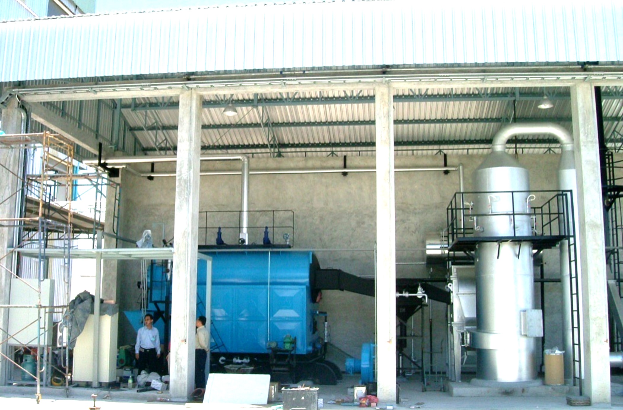
Frequently Asked Questions About Reading Coal-Fired Boiler Datasheets
What is the difference between a boiler datasheet and a boiler data book — and which one should I request before placing an order?
A datasheet is a concise summary — often one to three pages — of the guaranteed performance parameters: rated capacity, design pressure, efficiency, fuel specification, emissions limits, and major auxiliary loads. It exists for selection, budgeting, and tendering. The data book (sometimes called the equipment data manual) is a completely different animal: a full engineering package issued after contract award, containing heat balance calculations, P&IDs, nozzle schedules, foundation loads, and vendor drawing registers. Request the datasheet before you sign anything. Then write into the contract that the data book — or at minimum the heat balance sheet and nozzle schedule — must be delivered within 30 days of contract signature. Factories that resist this clause are worth questioning.
The datasheet shows 88% efficiency, but our energy audit measured only 82% in operation. What is causing the gap?
This gap is common and almost never the result of a dishonest datasheet — it is usually an operational reality. Five causes account for the vast majority of cases. First, actual coal quality deviates from the design coal: higher moisture or lower calorific value forces the furnace to work harder and increases unburned carbon losses. Second, the unit runs at partial load for extended periods; chain-grate stokers in particular drop efficiency noticeably below roughly 70% of rated output due to poor air distribution at reduced grate speed. Third, heat transfer surfaces are fouled — a layer of ash or slagging on superheater tubes as thin as 2–3 mm can cut heat absorption by several percent. Fourth, air leakage through worn expansion joints or inspection doors raises the excess air coefficient well above the design value, inflating dry flue gas losses. Fifth — and this one gets overlooked — economizer bypass dampers are opened during summer to avoid condensation in the flue duct, which defeats a meaningful chunk of the heat recovery the efficiency figure assumed.
Can I use a datasheet rated for Chinese bituminous coal to order a boiler for Indonesian sub-bituminous coal at 35% moisture?
No. Do not do this. A boiler designed around bituminous coal with, say, 10–15% moisture will have a furnace volume and grate area sized for a specific flue gas volume and combustion intensity. Feeding 35% moisture coal increases the mass of flue gas per unit of heat released, overloads the induced draft fan, and reduces furnace temperature enough to cause incomplete combustion — you will see high CO and rising carbon-in-ash. The grate heat release rate, which for chain-grate stokers typically runs 0.8–1.2 MW/m² depending on coal type, needs to be recalculated. Ask the manufacturer for a formal fuel adaptability assessment and a re-rated heat balance. This is standard practice and a legitimate manufacturer will not resist it.
What does BMCR mean on a power boiler datasheet, and how does it differ from ECR?
BMCR — boiler maximum continuous rating — is the highest output the boiler can sustain continuously without damage. ECR (economic continuous rating) is the output at which the boiler operates at peak thermal efficiency, and it typically falls around 85–90% of BMCR depending on design. Turbine heat balance calculations are normally anchored to ECR, not BMCR. If your process team is sizing steam headers or turbine inlet conditions using the BMCR figures, they are building in an optimistic assumption that the plant will rarely, if ever, achieve in steady operation.
My datasheet quotes NOx at 250 mg/m³ at 6% O₂, but the local permit says 150 mg/Nm³ at 11% O₂. Are these equivalent?
They are not directly comparable — you must normalize to the same oxygen reference before drawing any conclusion. The correction formula is:
C_normalized = C_measured × (21 − O₂_reference) / (21 − O₂_measured)
Applying this: 250 × (21 − 11) / (21 − 6) = 250 × 10/15 ≈ 167 mg/Nm³. That exceeds the 150 mg/Nm³ permit limit, so additional control — SNCR at minimum, possibly SCR depending on variability — would be required. Always run this calculation yourself. Do not accept a verbal assurance from a sales engineer that the figures are “basically the same.”
250 mg/m³ NOx at 6% O₂ is equivalent to approximately 167 mg/Nm³ at 11% O₂ reference, using the standard oxygen correction formula.True
The standard reference-condition correction (21−O₂ref)/(21−O₂meas) applied to 250 mg/m³ at 6% O₂ gives 250×(10/15)=166.7 mg/Nm³ at 11% O₂, which exceeds a 150 mg/Nm³ permit limit.
How do I verify that the stated boiler capacity is not inflated?
Request the heat balance calculation sheet as a contractual deliverable. With the rated steam enthalpy and feedwater enthalpy from the datasheet, you can back-calculate the required heat input and check it against the stated fuel consumption and coal LHV. Cross-check the grate area against published heat release benchmarks for the combustion technology — chain-grate stokers typically run 0.7–1.1 MW/m² of effective grate area; if the numbers imply significantly more, that capacity claim deserves scrutiny. Manufacturers with real design depth will hand over this sheet without hesitation.
What auxiliary documents should always accompany a coal-fired boiler datasheet for an EPC project?
At minimum: a motor list with installed and operating kilowatt ratings, an instrument and control I/O list, a utility consumption summary covering make-up water flow, cooling water, instrument air pressure and volume, and peak electrical demand, a nozzle schedule with flange ratings and stream conditions, and a foundation load drawing showing static and dynamic loads at each support point. Any EPC tender package missing these attachments is genuinely incomplete — and filling the gaps during detailed engineering is where cost overruns quietly accumulate.
References
BPVC Section I — Rules for Construction of Power Boilers — ASME
Performance Test Codes — Fired Steam Generator Performance Testing — ASME
National Board Inspection Code — Boiler Installation, Inspection, Repair and Alteration — National Board of Boiler and Pressure Vessel Inspectors
Boiler Efficiency and Combustion — Fuel, Air and Boiler Performance — Spirax Sarco
Coal Analysis and Production Information — Thermo Fisher Scientific
Pulverized Coal-Fired Boilers — Boiler Technology — GE Vernova
Boilers for Steam Power Plants — Boiler Technology and Specifications — Mitsubishi Power
PowerFluid Circulating Fluidized Bed Boilers — Fuel-Flexible Boiler Technology — ANDRITZ
Boiler Fittings and Mountings — Essential Boiler Components — Spirax Sarco
How to Read an Industrial Coal-Fired Boiler Datasheet and Technical Specification? Read More »