
How to Troubleshoot Common Issues in Industrial Biomass Boilers?
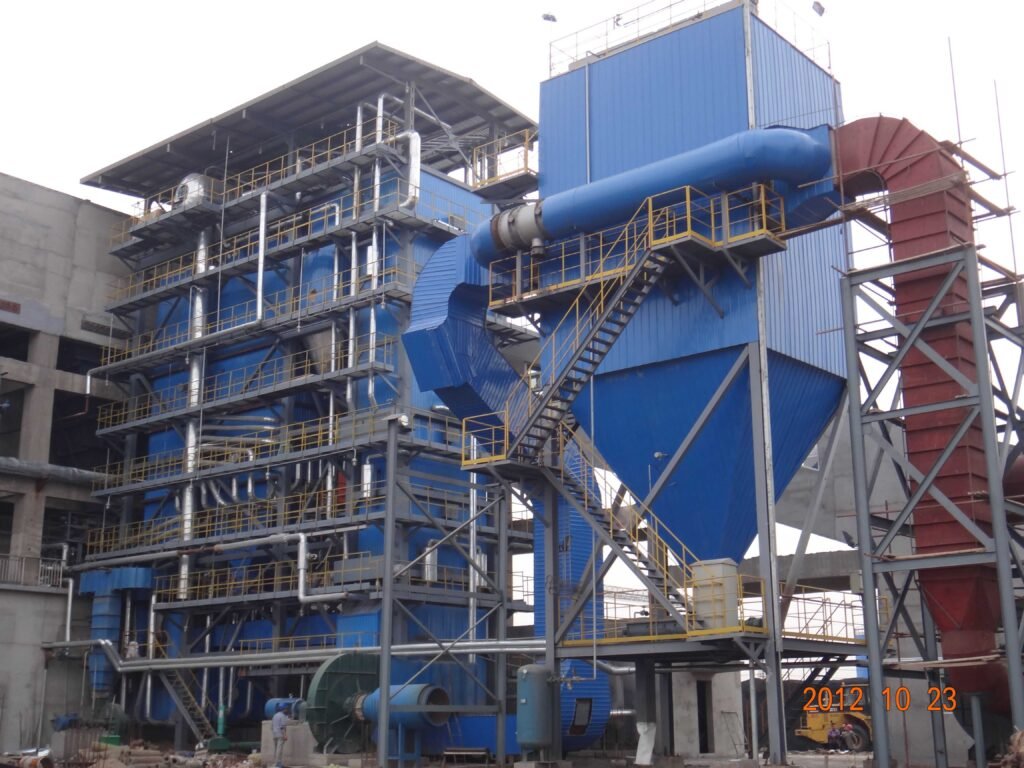
Biomass boilers have a reputation for being temperamental, and on the plant floor that reputation is earned. Fuel moisture swings, inconsistent chip sizing, slagging on the grate, erratic steam pressure — these aren’t edge cases, they’re the weekly reality for most operators running agricultural residues or mixed wood waste. Left unaddressed, a single unresolved fault cascades fast: a partially blocked fuel feed starves combustion, O₂ climbs, you dump excess air to compensate, thermal efficiency drops from a reasonable 85% toward the low 70s, and fuel consumption quietly eats your operating margin while nobody’s watching the trend log.
The most effective way to troubleshoot industrial biomass boilers is to work systematically through four domains — fuel quality, combustion control, heat transfer surfaces, and mechanical/feed systems — starting with real-time flue gas O₂ and CO readings, then cross-checking fuel moisture, grate condition, and draft balance before touching any setpoints. Most faults trace back to fuel variability or air distribution, not equipment failure.
What makes biomass troubleshooting genuinely harder than coal or gas is that the fuel itself is a moving variable. A gas boiler running on pipeline gas sees almost no feedstock variation. A biomass unit burning whatever the supplier delivered last Tuesday might be dealing with 25% moisture content one week and 48% the next — and both look the same coming off the conveyor. That variability hides inside the system until it shows up as a symptom: a steaming problem, a slagging event, an unexplained CO spike at 2 a.m. The sections below work through each failure mode the way a commissioning engineer would: start with what the instruments are telling you, then dig into the physical cause.
Diagnosing Combustion Instability: Flame Failure, Incomplete Burn, and Low Steam Output
The single most common complaint from biomass boiler operators — regardless of whether the unit is a 10 t/h traveling grate or a 75 t/h bubbling fluidized bed — is some variation of “the boiler won’t hit rated output.” Before you start pulling inspection hatches or blaming the burner management system, work through a structured first-response sequence. Jumping straight to hardware usually wastes time and occasionally causes damage.
First-Response Checklist: Fuel Before Everything Else
Start at the fuel. This sounds obvious, but in practice fuel quality is the culprit in probably 60–70% of the combustion instability cases I’ve seen, and it’s the last thing some operators want to admit because it implicates their fuel procurement.
Check moisture content first. A quick Ohaus or Sartorius moisture balance at the conveyor head gives you a reading in under 10 minutes. Fuel arriving above 45–50% wb is going to cause problems on virtually any grate system; above 50% you’re essentially fighting the boiler’s own evaporative load trying to sustain ignition. The practical target for stable continuous combustion on a moving grate is below 35% wb. If incoming fuel has crept above that — seasonal effect in wet climates is real; woodchip and rice husk moisture swings of 15–20 percentage points between dry and rainy season are not unusual — you need either supplemental drying, blending with drier fuel, or a temporary derating of output.
Particle size consistency matters too. For a reciprocating or vibrating grate, target 30–50 mm average with reasonably tight distribution. Oversized chunks (>80 mm) stall on the grate surface, create local hot spots, and pass through partially unburned. Undersized fines (500 ppm measured at the economizer outlet) that indicate incomplete combustion. Running above 1.7 dilutes furnace temperature, drops thermal efficiency, and increases fan power consumption — sometimes enough to matter on your electricity bill.
A calibrated flue gas O₂ analyzer in the duct — upstream of the air preheater if you have one — gives you real-time feedback. Target 5–8% O₂ (vol, dry basis). If O₂ is reading above 9% with your output still low, you have excess air without the heat to show for it, which usually points to a cold grate section or dead zone rather than an air quantity problem.
Flue gas O₂ reading alone is sufficient to confirm complete combustion in a biomass boilerFalse
O₂ measures excess air quantity, not combustion completeness. You need simultaneous CO measurement (or at minimum CO₂/CO ratio) to confirm burnout. A high O₂ reading can coexist with high CO if air distribution is uneven across the grate.
Underfire and Overfire Air Imbalance
Underfire air (UFA) passes through the grate to gasify and burn the fixed char bed. Overfire air (OFA) jets into the furnace above the bed to complete combustion of volatiles and CO. If one is off relative to the other, you’ll see it clearly in your flue gas composition.
Symptoms of UFA deficit: low bed temperature, poor char burnout, heavy bottom ash with visible unburned carbon. Symptoms of OFA deficit: CO climbing above 500 ppm, visible brown or grey smoke at the stack, furnace temperature dropping despite the fuel feed running normally.
Root causes are usually mechanical. Blocked air distribution ports under the grate clog with fine ash over time — especially with high-silica fuels like rice husk or sunflower husk. Damper actuator failures are common on older installations; the actuator reports 60% open via the DCS but the damper blade is seized at 30%. Pull the actuator linkage and verify physical position independently. On OFA, check nozzle erosion — the jet velocity drops as the nozzle opening enlarges from ash abrasion, and a 20% increase in nozzle area roughly halves jet penetration depth, which means the OFA never reaches mid-furnace.
Fuel Feeding Faults
Screw conveyor bridging is a persistent nuisance with stringy biomass like bagasse or long-fiber wood waste. The conveyor motor current climbs, the feed rate drops, and the boiler starts starving without any alarm specifically identifying the cause. Install current monitors with trending on each conveyor segment; a gradual upward drift in running current is an early warning. Rotary feeder jamming is typically caused by oversized particles wedging in the rotor pockets — either improve upstream screening or increase pocket clearance during the next scheduled outage.
High-moisture fuel clumping is worse in cold ambient conditions; material that flows freely in summer can arch completely across a hopper throat in winter.
Grate-Specific Dead Zones and Burn-Out Adjustment
On reciprocating grates, dead zones form when one or more grate sections stop moving — usually a hydraulic cylinder seal failure or a seized pivot bearing. The symptom is a stripe of thick, partially burned fuel bed visible through the inspection port, running perpendicular to the direction of travel. Left alone, that cold zone progressively chokes airflow through that section and the output loss compounds.
Adjust grate speed (stroke frequency) as a first corrective step; slowing the entire grate gives the fuel longer residence time and can partially compensate for a weak section. But this is a workaround, not a fix — the mechanical fault needs attention at the next shutdown.
Instrumentation and Control Loop Checks
Thermocouple calibration in the 1,000–1,200 °C furnace zone drifts faster than most operators expect. A Type K or Type N thermocouple in a heavy ash-laden biomass furnace may read 40–80 °C low after 6–12 months of continuous service, which means the combustion control loop is trimming air supply downward based on false temperature data.
Pressure transmitter zero drift on the windbox is another quiet troublemaker. If the transmitter consistently reads 10–15 Pa high, the control logic thinks UFA is adequate when it isn’t.
When to Escalate to a Full Audit
If furnace temperature is persistently below 850 °C despite correcting fuel quality and air distribution, do not keep running. Sustained sub-850 °C operation means incomplete tar and volatile burnout, which accelerates tar deposition on the superheater and economizer, raises CO and unburned hydrocarbon emissions, and in extreme cases can create a hazardous condition in the flue ductwork. At that point, schedule a grate inspection shutdown, pull a full fuel quality audit from your supplier, and review your combustion control tuning parameters with someone who has biomass-specific PID loop experience — standard combustion tuning from a gas or pulverized-coal background does not translate directly.
Identifying and Clearing Slagging, Fouling, and Ash Blockages in the Combustion Chamber and Convection Pass
Slagging and fouling are, in my experience, the single biggest reason biomass boilers fall short of rated output over a full operating year. Unlike coal ash, which behaves fairly predictably once you know the seam, biomass ash chemistry swings wildly depending on what’s coming off the field that week. That variability is what makes this problem so persistent — and so frequently misdiagnosed as a combustion issue when it’s actually an ash deposition issue.
Why Biomass Ash Fuses at Lower Temperatures Than You’d Expect
The root cause is alkali metals — primarily potassium (K) and sodium (Na) — combined with chlorine, which are concentrated in agricultural residues and short-rotation energy crops. These compounds act as fluxing agents, driving ash fusion temperatures (AFT) down to the 900–1,050 °C range for straw and rice husk ash, versus roughly 1,100–1,250 °C for clean wood chips. Furnace exit gas temperature (FEGT) in a well-designed biomass boiler typically runs 850–1,050 °C depending on fuel type and load, which means a straw-fired unit is already operating uncomfortably close to the sticky zone. Push load up slightly, or let air distribution drift, and you’re depositing molten or semi-molten ash on superheater pendants and the upper furnace walls before the shift supervisor notices anything unusual.
Biomass ash from high-potassium fuels like straw and rice husk has a significantly lower ash fusion temperature than wood chip ash, increasing slagging risk at normal furnace operating temperatures.True
K and Na-rich ash forms low-melting-point eutectic compounds (e.g., K2SO4-KCl mixtures) with fusion temperatures starting around 900°C, well within the operating range of biomass furnaces, which is well-documented in combustion chemistry literature and confirmed by operational experience with agricultural residue boilers.
Recognizing Slagging Before It Becomes a Crisis
The instrument signals come first — a gradual drop in steam pressure or superheated steam temperature at constant fuel feed rate, a rising draft differential across the superheater or upper evaporator bank, and an unexplained increase in auxiliary fan power. These are not subtle if you’re watching trends rather than snapshots. Observation port checks (ideally every 4–6 hours during the first week on a new fuel batch) will show bridging slag formations on the furnace walls or pendant tubes that no flow meter will reveal.
Clinker on the grate is a related but distinct problem. High furnace temperatures combined with uneven primary air distribution — often a plugged nozzle cap on one air zone — create local hot spots where ash sinters into dense clinker. For high-ash fuels like rice husk or bagasse, grate inspection every 8–12 hours is realistic, not conservative. Manual de-slagging tools (essentially long-handled chisels and scrapers) handle fresh accumulations; pneumatic lances are more effective for material that’s had time to harden. Don’t let clinker build up over an entire shift thinking you’ll deal with it at the end — it becomes significantly harder to remove and can damage grate bars.
Convection Pass Fouling and Sootblower Practice
Fly ash from biomass tends to be fine, sticky, and electrically resistive. In the convection pass, where flue gas cools through roughly 400–600 °C, partially molten ash particles bond to tube surfaces and then capture additional dry particles in a snowball effect. The resulting deposits are thermally insulating and restrict gas flow — both effects reduce heat transfer efficiency and raise backpressure simultaneously.
Sootblowers — either steam retractable or rotary air type — are the standard countermeasure. Steam sootblowing pressure typically operates in the 0.8–1.2 MPa range; go below that and you get inadequate lance velocity, go above and you risk tube erosion, particularly on thinned or corroded tubes. Sootblowing schedules should be based on differential pressure trending across each pass rather than fixed clock intervals. A plant running clean wood pellets might sootblow once every 8 hours; a plant burning 40% rice husk co-fired with wood might need it every 3–4 hours on the superheater zone.
Economizer and Air Preheater Plugging
The air preheater (APH) cold end is where a different failure mode appears. When flue gas temperature drops below the acid dew point — roughly 130–150 °C for biomass fuels containing significant chlorine — HCl condenses on metal surfaces and reacts with fine ash to form a corrosive, cement-like deposit that can blind an APH basket in a matter of days. The fix is operational: maintain cold-end metal temperature above the dew point by controlling the incoming combustion air temperature (using a steam coil air heater or recirculating warm flue gas), especially during low-load operation in cold ambient conditions. Winter startups on unheated sites are a known risk period.
Long-Term Mitigation and Design-Level Choices
Fuel blending is the most practical operational lever — mixing high-alkali straw with wood chips at a 30–50% ratio by mass can raise effective AFT by 80–150 °C, enough to move the operating point away from the sticky zone. Kaolin injection into the furnace is effective for K capture but adds cost and generates more ash volume; sulfur-based additives work on a similar principle but introduce their own flue gas chemistry complications. Neither is a substitute for getting the fuel blend right upstream.
At the design stage, tube spacing in the convection pass is a critical parameter for high-alkali fuels. Tighter pitches that look economical on a heat transfer calculation become maintenance nightmares in practice because sootblowers can’t clear deposits between closely spaced tubes. For fuels with K+Na content above roughly 0.3% (dry basis), widened transverse and longitudinal pitch in the superheater and first evaporator bank — along with extended sootblower lance coverage — is a design choice we factor in from the specification phase, not something added later as a retrofit.
Emergency De-Slagging Protocol
If a unit needs to come offline for mechanical de-slagging, cool-down rate matters. Rapid cooling stresses refractory — particularly around furnace nose and slag tap areas — and can cause spalling that turns a cleaning outage into a refractory repair. Controlled cool-down at no more than roughly 50–80 °C per hour through the 600–300 °C range is a reasonable target, though specific limits depend on the refractory specification and furnace geometry. Once cooled and ventilated, mechanical cleaning uses pneumatic chisels on the furnace walls and high-pressure water lancing in the convection pass. Before restart, a borescope inspection of accessible tube sections — especially the superheater outlet legs — confirms no bridging slag remains that could cause localized overheating at normal operating temperature.
Troubleshooting Steam Quality Problems: Carryover, Water Level Fluctuation, and Pressure Deviation
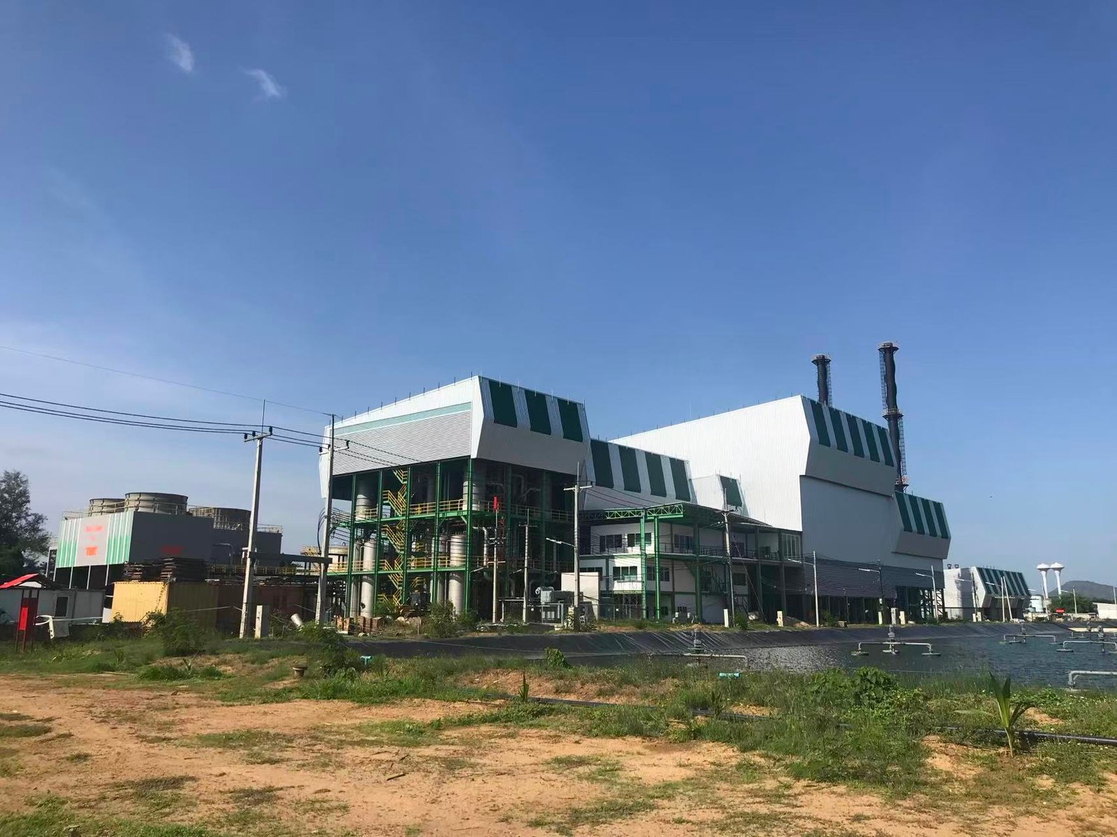
Steam-side and water-side faults are probably the most consistently misdiagnosed class of problems on biomass boilers. An operator sees dropping steam pressure or erratic output, assumes something is wrong with the fire, and starts chasing combustion settings — when the actual fault is sitting in the drum, the feedwater system, or a fouled blowdown line. Getting this separation right saves a lot of unnecessary fuel adjustment and, more importantly, prevents the kind of slow-developing damage that only shows up when you pull a tube bundle six months later.
Drum Water Level Instability and the Swell-Shrink Effect
Biomass boilers are particularly prone to sharp load swings because fuel quality and feed rate both vary. When load increases suddenly, the drop in drum pressure causes steam bubbles already forming in the water to expand — water level reads high even as actual water inventory is falling. That’s the swell. The reverse happens on load drop. Single-element feedwater control (responding to level only) will fight this response and either overfill or starve the drum depending on timing.
Three-element control — measuring feedwater flow, drum level, and steam flow simultaneously — compensates for the dynamic mismatch. In practice, single-element is acceptable on smaller units below roughly 10 t/h where load swings are gradual and the operator is experienced enough to anticipate them. Anything above that, or any plant running variable biomass feed, needs three-element as a baseline. Running single-element on a 20 t/h unit burning mixed agricultural residue is asking for a low-water trip every few weeks.
Steam Carryover: Priming, Foaming, and TDS Control
Wet steam at the header usually means one of three things: total dissolved solids (TDS) in the boiler water are too high, the steam drum separator internals are damaged or fouled, or the boiler is being pushed above its rated evaporation rate. GB/T 12145 and equivalent international standards generally target boiler water TDS below 3,000 mg/L for industrial steam boilers in this pressure class — though the tighter you can hold it, the better.
Foaming is the sneakier failure mode. Silica, oil contamination from condensate return, or elevated organic load from biomass-derived condensate can all cause a stable foam layer that carries moisture into the steam line without triggering a high-level alarm. If you’re seeing unexplained wet steam and TDS is within range, check for oil contamination first — even a few ppm of oil will foam aggressively at boiler temperatures.
Corrective blowdown should be two-stage: surface blowdown to remove dissolved solids and floating impurities, combined with periodic bottom blowdown to clear settled sludge. Don’t run surface blowdown continuously at high rate as an excuse to skip proper water treatment — you’re just throwing treated feedwater away and increasing makeup water demand.
Scale, Tube Overheating, and Feedwater Chemistry
Scale is a slow killer. A 0.5 mm calcium carbonate deposit on the waterside of a tube surface degrades local heat transfer by roughly 10%, and the effect compounds as the deposit thickens. Tube metal temperature rises to compensate — that’s how you get bulging, cracking, or outright tube failure on a boiler that looks fine from the outside. Feedwater hardness should be held below 0.03 mmol/L (as calcium and magnesium combined); anything above that consistently means your softener resin is exhausted, channeling, or undersized for the actual makeup flow rate.
A 0.5 mm scale layer on boiler tubes reduces local heat transfer efficiency by approximately 10%, increasing tube metal temperature and accelerating failure risk.True
Consistent with published thermal resistance values for CaCO3 scale; scale thermal conductivity is roughly 0.5–1.2 W/(m·K) versus steel at ~50 W/(m·K), creating a disproportionate resistance at even thin deposit thicknesses.
Seasonal variation matters here. Plants that increase biomass moisture handling in wet seasons often see increased makeup water consumption, which taxes the treatment system. Check regeneration frequency against actual throughput, not the nameplate design rate.
Pressure Deviation: Safety Valve Chatter and Control Lag
Safety valve chattering — the valve repeatedly lifting and reseating — is almost always a sign that operating pressure is running too close to the set pressure, or that the set pressure has drifted. Tolerance on set pressure should be within roughly ±3% of the stamped value; beyond that, retest and recertify. Running a boiler with a chattering safety valve is not a nuisance issue — it erodes the valve seat and will eventually result in a valve that won’t reseat cleanly.
Pressure control valve response lag on the steam header is worth investigating separately. If header pressure is dropping under load despite adequate drum pressure, the problem is often undersized pipework, a partially closed isolation valve someone forgot about, or a strainer screen that’s blocked with scale flakes or weld slag from a recent repair.
Drum Level Sensor Calibration
Differential pressure transmitters for drum level measurement develop zero offset errors over time, especially at elevated pressures where the reference leg density assumptions become sensitive to temperature variations in the instrument piping. In practice, cross-check DP transmitter readings against the independent gauge glass at least monthly. If they diverge by more than a few percent, don’t just adjust the transmitter offset blindly — check for condensate leg temperature changes, partial blockage of the tapping points, or a slow reference chamber leak first. Redundant level gauges (magnetic or reflex glass as a minimum) are not optional on any unit above 1.0 MPa.
Hot-Water Biomass Boiler: Different Faults, Same Diagnostic Discipline
On 70/95 °C or 115/130 °C hot-water biomass systems, the failure modes shift. There’s no steam drum to worry about, but expansion vessel undersizing causes system pressure to swing excessively with temperature, eventually lifting the relief valve on every heating cycle. Circulating pump head needs to be matched to actual system resistance — not the design calculation, but the measured resistance after installation, because pipework changes during construction are common and rarely documented.
Air pockets in the upper circuits mimic flow blockage symptoms almost exactly: poor heat delivery, uneven temperature across the distribution header, occasionally a gurgling sound in the pipework. The diagnostic difference is that air pockets clear (partially) when the system pressure is raised temporarily and the vent points are opened; a true blockage won’t. Automatic air vents on high points are cheap insurance; a plant that skips them will spend maintenance hours chasing phantom flow problems.
Resolving Emissions Exceedances: Particulate, NOx, SO2, and CO Control in Biomass Boilers
Emissions failures rarely announce themselves cleanly. What you usually see first is a CEMS trend drifting upward over a shift, or a regulator audit flagging a 72-hour average that crossed the limit — not a sudden spike with an obvious cause. The troubleshooting process for flue gas compliance is therefore part instrumentation check, part combustion diagnosis, and part equipment inspection, often running in parallel.
Reference limits worth keeping visible in the control room: particulate <30 mg/Nm³, NOx <200 mg/Nm³, SO₂ <35 mg/Nm³ — all corrected to 6% O₂ dry basis under EU IED and China GB 13271-2014. These are not the same as stack discharge concentrations at actual flue gas conditions, so always confirm which basis your CEMS is reporting before you call an exceedance real. Plenty of false alarms trace back to a misconfigured O₂ correction factor rather than any actual combustion problem.
High Particulate: Work Backwards from the Bag Filter
When particulate climbs, the bag filter gets blamed immediately, and honestly it is usually the right place to start. A pulse-jet cleaning cycle failure — whether a stuck solenoid valve, low compressed air header pressure (should typically be 5–7 bar at the manifold), or a clogged nozzle row — lets dust cake build past the point where differential pressure recovers between pulses. Differential pressure across the bags running above roughly 2.0–2.5 kPa when it should be 1.0–1.5 kPa is a reliable early indicator. Broken bags are less common but far more consequential; the Mg tracer leak test (introduce magnesium oxide upstream, sample downstream rows by compartment) localises which bag row has failed without pulling the entire filter offline.
Cyclone efficiency drops often get overlooked because the cyclone sits upstream and operators assume it is just a pre-separator. But if fuel moisture has crept up or particle size distribution has shifted — coarser chips, say, after a fuel supplier change — cyclone cut size may no longer match the incoming ash profile, pushing more load onto the bags than they were sized for.
ID fan speed changes deserve attention too. If the fan has been throttled to reduce power consumption or noise, actual face velocity through the bags drops, which sounds helpful but can actually cause re-entrainment from poorly cleaned sections. Conversely, running the fan faster than design increases face velocity and shortens filter bag life.
NOx: Fuel Nitrogen Is the Real Driver
Unlike gas or even coal firing, biomass NOx is dominated by fuel-bound nitrogen pathways — typical biomass N content runs 0.1–1.5% depending on species, with agricultural residues like straw or rice husk sitting near the high end. Thermal NOx is a smaller contributor at biomass furnace temperatures. That matters operationally because adding more combustion air to cure a CO problem will worsen NOx, often significantly.
Overfire air (OFA) ratio targeting 20–30% of total combustion air is the primary staged-combustion lever. If you have SNCR, urea injection rate tuning matters more than people expect: the molar ratio NH₃:NOx should sit around 1.0–1.5, and the injection point must be within the 850–1,050 °C window. Inject too low and the urea decomposes before the NOx reaction completes; inject too high and unreacted ammonia slips through, creating a secondary compliance problem with ammonia in the stack.
SNCR systems on biomass boilers operating below 850°C flue gas temperature at the injection point will produce significant ammonia slip regardless of urea dosing rate.True
The selective non-catalytic reduction reaction between urea-derived NH3 and NOx requires a minimum temperature of approximately 850°C to proceed efficiently. Below this threshold, urea decomposes but does not react with NOx, resulting in unreacted ammonia passing through the system — a condition called ammonia slip — which itself may trigger regulatory limits on NH3 emissions.
CO Spikes and What They Actually Mean
A CO spike is almost always a combustion instability symptom, not an isolated emissions event. Cross-referencing the CO trend against the O₂ trace is the first move: CO rising while O₂ also rises usually points to a wet fuel batch causing incomplete combustion with excess air; CO rising while O₂ falls points to an air supply problem — blocked undergrate air duct, grate sealing failure, or a fuel pile-up preventing air penetration. The operational response sequence is: increase underfire air in 5–10% increments, check fuel feed rate consistency (bridging in the hopper is common in cold, humid weather), and inspect the grate condition if CO persists.
SO₂ and HCl for High-Chlorine Fuels
Straw, energy crops, and some agricultural residues carry chlorine levels that produce HCl alongside SO₂ in flue gas. Dry sorbent injection (DSI) with sodium bicarbonate or hydrated lime handles both, with typical injection rates around 1.5–2.5 kg/GJ — the actual rate depends on fuel sulfur content, chlorine loading, and required removal efficiency. Under-injection failures often trace to the sorbent feeder rather than the dosing setpoint: bridging in the silo (especially after humid storage), a worn rotary valve, or a blocked pneumatic conveying line. A simple daily check of sorbent silo level against calculated consumption is worth building into the morning rounds.
CEMS Calibration: The Problem Nobody Wants to Own
CEMS drift is chronically under-managed on biomass installations, partly because the analyzers sit in a hot, dirty environment and partly because calibration failures do not always trigger alarms — the readings just quietly wander. Daily auto zero-and-span checks catch gross failures; quarterly manual calibration with certified reference gas is necessary to catch gradual drift in electrochemical O₂ cells (typical service life 12–24 months under normal conditions) and UV NOx analyzer lamp fouling. Audit log completeness is as important as measurement accuracy — regulators reviewing continuous emissions records will flag data gaps as exceedances in many jurisdictions.
For overseas projects where emission standards vary from EU IED to local equivalents, a well-configured flue gas treatment train — cyclone pre-separator, pulse-jet bag filter, SNCR or SCR depending on NOx targets, DSI for SO₂/HCl, and a properly sized ID fan — gives the flexibility to meet a wide range of permit conditions through operational tuning rather than hardware changes after commissioning. Getting the system sized and sequenced correctly at the design stage is where most of this compliance headroom actually comes from.
Diagnosing Feedwater System, Economizer, and Heat Recovery Circuit Failures
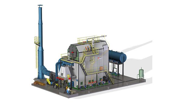
The heat recovery section is where a significant share of boiler efficiency either gets captured or quietly bleeds away. In practice, problems here tend to develop slowly — a few degrees of extra stack temperature, a slight upward creep in feedwater flow versus steam output — and operators don’t notice until a tube fails or the efficiency audit comes back looking embarrassing. Getting ahead of that requires knowing what to measure and what the numbers actually mean.
Feedwater Pump Cavitation
Cavitation announces itself clearly if you’re standing next to the pump: a rattling, gravel-in-a-can sound, often accompanied by erratic discharge pressure and visible flow oscillation on the outlet gauge. The root cause is almost always insufficient net positive suction head (NPSH). On biomass plants running variable loads — which is most of them — the deaerator operating pressure can drift lower than the setpoint, reducing the saturation temperature margin and allowing flashing at the pump suction.
First check: confirm the deaerator is holding its design pressure (typically 0.02–0.12 MPa gauge, depending on plant design). A clogged suction strainer is the other common culprit and takes about ten minutes to rule out. If strainer differential pressure is above roughly 30–50 kPa, clean it before chasing anything else. Raising deaerator operating pressure by even 10–15 kPa can resolve marginal NPSH situations quickly, though it means re-checking the thermal balance on the deaerator heating steam.
Deaerator Performance and Dissolved Oxygen
The feedwater dissolved oxygen (DO) target is below 7 ppb (0.007 mg/L) — that’s the threshold most boiler codes and chemical treatment programs are built around. Exceeding it consistently causes oxygen pitting, which shows up first in the economizer inlet header and lower drum circuits because those run at the lowest metal temperatures and highest dissolved gas exposure time.
Dissolved oxygen above 7 ppb in boiler feedwater is a recognized driver of pitting corrosion in economizers and steam drumsTrue
This threshold is established in ASME and EN boiler water quality guidelines; oxygen pitting is a well-documented failure mode in low-temperature economizer circuits exposed to inadequately deaerated water.
Verify DO with a calibrated inline meter, not just a grab sample — the deaerator vent valve operation matters too. A partially closed or stuck vent valve will let non-condensable gases accumulate. It’s a simple check that gets skipped more often than it should.
Economizer Tube Corrosion and Leak Detection
Biomass flue gas carries sulfur compounds and, depending on feedstock, significant chlorine — particularly with agricultural residues like rice straw or palm kernel shell. Below the acid dew point (typically 130–160 °C for sulfuric acid condensation, somewhat higher for hydrochloric acid depending on Cl content), the flue-gas-side tube surface becomes corrosive. This is low-temperature corrosion, and it’s distinct from the oxygen pitting that attacks the water side.
A practical early-warning method: track the feedwater flow versus steam flow mass balance continuously. A divergence of more than roughly 1–2% that isn’t explained by blowdown suggests a leak somewhere in the economizer circuit. Pressure drop trending across the economizer water side adds another data point — a rising trend on a clean system usually means internal narrowing from deposits or, in a leaking tube scenario, occasionally partial blockage from corrosion products.
Economizer Bypass Damper Operation
During cold start-up, the economizer tubes can be well below acid dew point, and routing hot flue gas through them before water circulation is established accelerates corrosion initiation. The bypass damper should remain open — directing flue gas around the economizer — until the feedwater circuit is flowing and tube metal temperatures are rising. Reinstating the damper too early on a cold morning is a habit that compounds over hundreds of start cycles. The correct procedure is to close the bypass gradually as load increases past roughly 30–40% of MCR, confirming economizer outlet water temperature is climbing at a controlled rate.
Heat Transfer Degradation: Fly Ash Fouling
Fly ash from biomass combustion, especially woody fuels, tends to be light and sticky enough to bridge between fins on extended-surface economizers. The diagnostic number to watch is approach temperature — the difference between economizer exit water temperature and the drum saturation temperature. A clean economizer running at design conditions will show a relatively tight approach. When that gap starts widening, say from a normal 15–25 °C to 40 °C or more, ash fouling is the likely cause before corrosion damage becomes the dominant factor.
Cleaning intervals vary considerably depending on ash loading, fuel alkali content, and whether sootblowers are installed. In high-alkali feedstock plants (sunflower husk, certain straws), monthly cleaning of the economizer gas path is not unusual. With clean wood chips, quarterly may be sufficient. The plant’s own trend data is more reliable than any generic schedule.
Air Preheater Cold-End Corrosion
Tubular air preheaters are common on biomass boilers; Ljungström rotary types appear on larger units. In biomass service, the cold-end elements or tubes see bisulfate and chloride deposits that plug passages and accelerate metal loss. Maintaining cold-end metal temperature above the acid dew point — often managed by recirculating warm air on the inlet side or using an air preheater bypass at low loads — is the primary mitigation. Basket or tube element replacement intervals in aggressive biomass service typically run 18–36 months, though plants burning high-chlorine fuels have seen failures in under a year. Inspecting cold-end elements at every planned outage is cheap compared to an unplanned replacement mid-campaign.
Thermal Efficiency Testing Protocol
Running an indirect efficiency test per ASME PTC 4 or EN 12952-15 gives you a defensible baseline and, more usefully, points to which loss category is responsible for any shortfall. The key measurements are flue gas temperature at economizer exit, flue gas O₂ (target 5–8% vol, dry basis for biomass), CO concentration, and unburnt carbon in bottom and fly ash. A high stack temperature with normal O₂ points to heat transfer fouling. Elevated CO with normal O₂ suggests incomplete combustion — possibly a grate or air distribution problem. High unburnt carbon drives up the solid unburnt loss and usually traces back to fuel sizing, moisture above roughly 50% wet basis, or insufficient residence time. Each of those measurements maps to a specific corrective action, which is the whole point of doing the test rather than just reading the installed efficiency meter.
-scaled.jpg)
Fuel Handling System Faults: Conveying, Storage, and Feeding Equipment Troubleshooting
Most unplanned biomass boiler shutdowns I’ve seen don’t start inside the furnace. They start upstream — a blocked screw feeder, a bridged silo, a worn rotary airlock that nobody checked during the last scheduled inspection. The combustion system gets blamed because that’s where the alarm triggers, but by then the real fault is already 20 minutes cold.
Biomass Storage: Spontaneous Combustion and Compaction
Wood chips and agricultural residues can self-heat in storage, especially during warm, humid seasons or when freshly delivered high-moisture material is heaped against older dried stock. The practical early warning is continuous CO monitoring in the silo headspace — CO tends to rise well before temperature sensors detect anything meaningful. A threshold of roughly 50 ppm should trigger an inspection; anything above 100–150 ppm warrants a controlled drawdown and possible partial evacuation of the silo. Temperature sensors alone, placed only at the top of the pile, are notoriously slow to respond because heat stratification inside a packed fuel mass is uneven. At minimum, fit sensors at three vertical levels on opposing walls.
Moisture migration causes compaction and bridging — arguably more common than fire risk and just as damaging to availability. Wet biomass, particularly wood residues above about 40% moisture (wb), develops cohesive strength under its own weight. The fuel essentially cakes around the outlet funnel. Anti-bridging devices — pneumatic hammers, vibrating bin activators, or live-bottom screws — are standard mitigations, but they get disabled or worn and nobody notices until the feeder starves. Build a daily check of bin activator operation into the shift log.
Belt Conveyors and Bucket Elevators
Belt misalignment is the chronic fault here. Sticky biomass (fresh wood chips, bark, fermented residues) builds up asymmetrically on head pulleys and return rollers, shifting the running centerline. Laser alignment tools — the same ones used for pump-shaft alignment — work well for conveyor pulley checks and are worth the minor investment over the traditional “chalk line and eyeball” approach. Edge-wear on the belt is your first visual indicator; ignored, it leads to spillage and eventually belt failure.
Speed sensors on conveyors deserve special attention. A failed speed sensor will report “conveyor running” to the DCS even when the belt has stalled or slipped. This is a real trap: the control system continues calling for feed, the boiler starves, and the operator assumes a combustion fault. Check that speed sensor signals are cross-verified against motor current draw in the control logic.
Screw Conveyor Blockages
Oversized particles, wire fragments from baled straw, stones picked up during field collection — biomass fuel is genuinely heterogeneous, and the fuel feed screw is where heterogeneity bites hardest. Keep inspection hatches accessible and unobstructed; in practice, they get buried under spilled fuel within weeks of commissioning if nobody enforces housekeeping.
A torque-limiter coupling provides better protection than a shear pin on biomass screw feeders in continuous operation.True
A shear pin requires physical replacement after each blockage event, causing repeated downtime of 15–30 minutes per incident. A torque-limiter automatically resets after the obstruction clears, and its slip torque can be calibrated to the screw's rated load — reducing downtime frequency significantly on fuels with variable particle size.
Shear pins are fine for low-frequency faults, but on abrasive or heterogeneous feedstocks, a torque-limiter is usually the better long-term choice.
Rotary Airlock Feeders
The rotary airlock between the feed chute and the furnace is easy to overlook until it fails. Its job is to feed fuel while blocking furnace pressure from propagating back up the fuel bin — air ingress through a worn or poorly sealed airlock causes erratic pressure readings in the fuel bin and can destabilize the primary air control loop.
Rotor tip wear rate depends heavily on fuel abrasiveness. Rice husk and bamboo dust are significantly harder on rotor tips than wood chips. On those fuels, tip replacement intervals of 4,000–7,000 operating hours are realistic depending on rotor material (cast iron versus hard-faced overlay); on softer fuels, the same rotors may last two to three times longer. Tracking wear progression with periodic tip-clearance measurements — rather than waiting for symptoms — prevents the sudden step-change in air leakage that disrupts combustion control.
Fuel Metering and Dryer Integration
Loss-in-weight feeders drift over time, particularly if the load cells underneath the weigh hopper accumulate dust or the tare weight shifts after maintenance. A static calibration (dead-weight check) tells you the sensor is reading correctly at rest; a dynamic calibration — running a measured quantity through and comparing against the feeder’s totalizer — is what actually matters for combustion loop accuracy. Quarterly dynamic calibration is reasonable on most plants; monthly if fuel density varies significantly between deliveries.
For high-moisture feedstocks, inline dryers (flue gas or steam-tube type) add interlock complexity. The dryer fire detection system must be hard-wired to both the dryer feed shutoff and the boiler’s main fuel trip — a software interlock alone is not sufficient. In one scenario typical of agricultural-residue plants, a dryer temperature excursion triggered a fire suppression system that doused the dryer but left the boiler fuel feed open; the control logic had not been set up to trip the feed screw simultaneously.
Protecting Availability Through Fuel Specification in EPC Contracts
The cleanest way to prevent fuel handling faults is contractual: define acceptable moisture content (typically ≤35% wb for direct-fed grate systems, ≤25% for screw-fed units without a dryer), particle size distribution (usually 95% passing a specified mesh, with zero tolerance for tramp metal or rocks), and bulk density range. Include penalty clauses for off-spec deliveries — without financial consequence, fuel suppliers default to whatever is cheapest to deliver. In practice, a well-written fuel specification in the EPC contract saves more operational headaches than any single piece of handling equipment upgrade.
Refractory and Pressure Part Inspection: Detecting Tube Failures, Cracks, and Structural Degradation
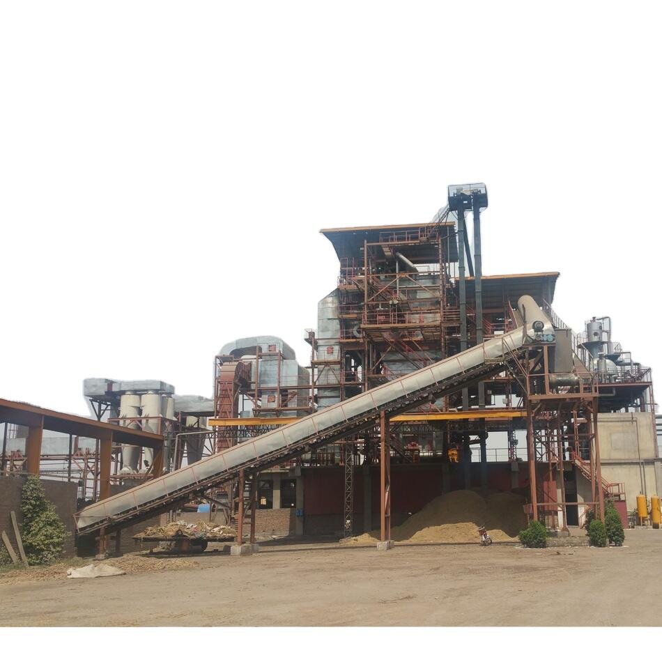
Structural failures in biomass boilers rarely announce themselves. By the time an operator notices a wet spot on lagging or a sudden pressure drop, the damage has usually been progressing for months — through micro-cracks in welds, thinning tube walls near the furnace nose, or a section of high-alumina castable that has quietly spalled away from the furnace floor. A disciplined inspection program is the only way to stay ahead of it.
Refractory Damage: What Biomass Does Differently
Biomass combustion puts refractory under a distinct stress pattern compared with coal or gas firing. Frequent load swings — common in process plants where steam demand tracks a production shift schedule — drive repeated thermal cycling in the lower furnace zone. Castable refractories without adequate expansion joints crack and spall. That is expected over time. What accelerates it in biomass service is alkali attack: potassium and sodium compounds in wood, rice husk, and agricultural residues react with aluminosilicate binders in standard castable, progressively degrading the matrix. For biomass furnace linings, specify high-alumina castable at 40% Al₂O₃ minimum — 50–60% where the fuel has elevated K₂O and Na₂O content, which you can estimate from proximate/ultimate analysis before commissioning. Cheaper 35% Al₂O₃ material saves money on day one and costs far more during the first major outage.
Erosion is a separate problem near secondary air nozzles and grate air ports, where particle-laden flue gas velocity can reach 15–25 m/s depending on furnace geometry. That kind of localized erosion chews through 20 mm of castable in 6,000–10,000 hours if the original design did not include wear tiles or silicon carbide overlays in those zones.
The practical inspection trigger is an external shell temperature more than roughly 70 °C above ambient, measured by IR thermography during operation. A handheld thermal camera during a walk-around takes about 20 minutes and will show you exactly where refractory has separated. Elevated fuel consumption with no obvious combustion cause — say, a 3–6% increase in specific fuel rate over a quarter — should prompt the same check. The heat is going somewhere.
Pressure Part Inspection: Schedule and Methodology
Ultrasonic thickness (UT) measurement should be done every 5,000–8,000 operating hours on the zones that earn the most wear: furnace nose tubes, superheater pendant tube banks, and economizer tube bends. The interval depends on fuel ash abrasiveness — hard silica-rich ash from rice husk warrants the shorter cycle. Calculate minimum acceptable wall thickness against ASME BPVC Section I (PG-27 for straight tubes) or EN 12952-3, using actual operating pressure and temperature, with the appropriate material allowance. Do not use nominal wall thickness as your retirement criterion; use the calculated minimum, which on a typical 3.0 MPa biomass boiler might be 3.5–4.5 mm depending on tube OD and grade — but run the numbers for your specific unit.
Chlorine-induced high-temperature corrosion in biomass superheaters becomes significantly more aggressive above approximately 550 °C metal temperature.True
Chlorine from biomass fuels (particularly straw, energy crops, and demolition wood) forms alkali chlorides that deposit on tube surfaces. Above roughly 550 °C, these react with the protective oxide layer, causing rapid sulfidation-oxidation corrosion. This is well-documented in EN 12952 guidance and peer-reviewed combustion literature.
For high-chlorine fuels — straw, energy crops, demolition wood — tube metal temperatures above 550 °C move you into aggressive chlorine-induced corrosion territory, and standard T91 or SA-213 T22 is not adequate. Material upgrades to TP347H are a common first step. Where chlorine is severe (fuel chlorine above roughly 0.3% db), Alloy 625 weld overlay cladding on the first few superheater rows is worth the capital cost versus a tube replacement every two or three years. Get a fuel chemistry report before you spec the superheater material — it is the one piece of information that changes the answer most.
Water-Side and Weld Inspection
Internal borescope inspection of the steam drum and headers should happen during each annual outage. You are looking for scale thickness, pitting, and deposits at low points in headers. Post-chemical cleaning acceptance criteria are concrete: rinse water iron concentration below 50 mg/L, measured from the final flush. Above that, the passivation step is not complete and the clean iron surface will begin corroding almost immediately. HCl-based cleaning is faster; citric acid is gentler on older or thinner-walled components. Which one you use depends on scale type and the unit’s history.
Weld inspection on drum nozzle connections and tube-to-header joints should include dye penetrant (PT) and magnetic particle (MT) during every annual outage. These are quick and cheap relative to the cost of a drum failure. For thick-wall components — typically drum shell welds above 30–40 mm — radiographic testing (RT) or phased array UT (PAUT) gives you volumetric defect information that surface methods cannot. PAUT in particular has become more accessible in recent years and is worth the extra cost on any component you cannot afford to fail.
Keeping the Technical Dossier Current
Every repair, thickness reading, and inspection report belongs in the boiler’s technical dossier. Statutory inspection bodies in Europe (PED), North America (ASME S/U stamp jurisdiction), and under China’s TSG G0001 all require traceable records of design pressure, material certificates, pressure test results, and repair history. In practice, many overseas plants fall behind on documentation, and it creates real problems at insurance renewal or during third-party audits.
Taishan Group supplies full certification packages for export units — including material test reports, stamped drawings, and third-party inspection dossiers — configured to the destination country’s regulatory framework from the outset, rather than retrofitting documentation after installation. That matters when a local inspector shows up and wants to see the original hydro test certificate.
Control System and Instrumentation Faults: DCS, Interlocks, and Safety Valve Diagnostics
Control system faults are probably the most frustrating category in biomass boiler troubleshooting — partly because the physical symptoms (a trip, poor load response, erratic pressure) look identical to combustion or mechanical problems, and partly because operators without strong instrumentation background tend to blame the burner or the fuel before they ever open the DCS trend screen.
Why Your Coal-Tuned PID Will Not Work on Biomass
A pressure controller tuned on a coal-fired or gas-fired boiler will almost always perform poorly on biomass, sometimes dangerously. The process gain is different. The dead time is longer, because grate ignition and fuel bed response are inherently slower than pulverized coal or gas flame. The time constant shifts depending on fuel moisture — a load of wet chips at 45% moisture (wb) burns quite differently from dry pellets at 18%, and the steam pressure responds at a noticeably different rate.
The right approach is to run open-loop step tests at three load points — roughly 50%, 75%, and 100% of rated output. Record pressure response, fuel feed rate, and air flow for each step. From those tests you can extract the process gain, dominant time constant, and approximate dead time for each operating region, then use those figures to calculate PID parameters properly rather than guessing. In practice, biomass boilers often need a slower integral term and more conservative derivative action than the previous coal-tuned parameters. Aggressive integral wind-up on a slow-responding grate furnace causes pressure hunting and, eventually, spurious MFT events.
Tracing Spurious Master Fuel Trips
When a biomass boiler trips and the operator says “it just shut down for no reason,” the first step is the historian. Pull the 30-second trend around the trip timestamp for: drum level, furnace pressure, fuel feed pulse count, and flame scanner output. In most cases the root cause is visible within two or three minutes of looking — a level sensor that dipped momentarily due to swell, a furnace pressure spike from a grate clinker falling, or a fuel feed conveyor that paused for three seconds and dropped below the flame-proving threshold.
Genuine trips and sensor-induced trips require different responses. A genuine low drum level trip needs a feedwater investigation. A sensor-induced trip that you bypass and restart without root-causing is a safety liability.
Most spurious MFT events on biomass boilers can be traced to sensor faults or signal noise rather than actual process hazards.True
Historian analysis of trip logs in grate-fired biomass installations consistently shows a high proportion of trips attributable to impulse line blockage, scanner contamination, or transmitter calibration drift rather than genuine process upsets — though each trip must still be individually verified before being classified as spurious.
The common culprits: fly ash blocking pressure transmitter impulse lines (especially on the furnace pressure measurement, where the target range is −20 to −50 Pa), UV scanner lenses fouled by condensate or fine dust, and drum level transmitters affected by density compensation errors during load swings.
Flame Scanner Specifics
UV scanners fail quietly. Condensate from a poorly heat-traced cable or dust accumulation on the sight glass reduces signal amplitude below the prove threshold, and the boiler trips — often at night when fuel moisture is higher and flame intensity is marginally lower anyway. Clean the lens every scheduled maintenance cycle; verify sensitivity threshold setting against a known-good flame signal. IR scanners have a different problem: hot refractory background radiation can saturate the detector, causing a continuous “flame present” signal even during a real flameout. If your IR scanner is reporting flame during a cool-down purge, the sensitivity threshold is set too high or the field-of-view angle is picking up refractory rather than the active combustion zone. Realign the scanner and reset the threshold.
Draft Control and Furnace Pressure Management
VFD speed mismatch between the ID fan and FD fan is one of the faster ways to create a furnace pressure excursion. In manual or during control switchover, if the ID fan slows before the FD fan responds, furnace pressure can swing positive within seconds. Normal operating target is negative draft, typically −20 to −50 Pa at the furnace exit, depending on boiler design. Positive furnace pressure blows hot gas through sealing gaps, damages refractory joints, and creates a genuine safety hazard for operators nearby.
Check impulse line routing on furnace pressure transmitters. Lines that run horizontally or with low points will accumulate fly ash over weeks and eventually block — the transmitter then reads a fixed stale value, draft control loses its feedback signal, and you get an unexplained pressure excursion. Slope all impulse lines to drain, and include a manual purge valve at each tap.
Safety Valve Testing and Maintenance
A safety valve that chatters or sticks open is not just a nuisance — it represents set-pressure drift, seat leakage, or incorrect blowdown adjustment. Per ASME requirements, set pressure tolerance is ±3% of nameplate, and blowdown (the difference between opening and reseating pressure) should be below 10% of set pressure. For in-situ verification, a gag-and-lift test lets you check that the valve opens at the correct pressure without fully relieving the system. If the valve chatters, the most common causes are a set pressure too close to operating pressure (insufficient margin, usually the design called for 3–5% margin but operating pressure crept up) or a worn seat.
Bench testing is warranted when: the valve has operated (actually popped) during a real overpressure event, when the seat shows visible erosion, or when in-situ testing shows set pressure has drifted more than 3% from nameplate. Do not simply re-gag and continue running.
Instrumentation Redundancy and Loop Integrity
For critical measurements — drum level, furnace pressure, steam temperature — single-point sensing is a reliability and safety risk. A 2oo3 voting architecture on drum level is reasonable for any boiler above roughly 10 t/h; at minimum, run dual transmitters on separate process connections with independent impulse lines. For steam temperature, thermocouple cold-junction compensation errors are a common source of 5–15°C reading offset, particularly in enclosures that experience wide ambient temperature swings seasonally. Verify cold-junction compensation on a scheduled basis, not just at commissioning.
For 4–20 mA loop checks, a loop calibrator connected at the field instrument should confirm signal at both 4 mA (zero) and 20 mA (span) before trusting any transmitter reading after maintenance. Technicians sometimes reconnect wiring incorrectly after tube cleaning and don’t notice until the next shift.
Remote Monitoring and Cybersecurity for Overseas Projects
For EPC projects where the boiler supplier provides remote technical support, a properly configured VPN tunnel to the SCADA historian is worth more than any site visit in the first year of operation. Key KPIs to log at 1-minute intervals as a minimum: boiler thermal efficiency (calculated from flue gas O₂ and stack temperature), availability factor, and specific fuel consumption per unit of steam output. These three together will usually surface a developing problem — gradual fouling, fuel quality drift, a control loop that’s slowly losing performance — weeks before it becomes an outage.
Cybersecurity on these connections is not optional. Segment the boiler control network from the plant business network, restrict SCADA remote access to named IP addresses through the VPN, and disable any default vendor accounts before commissioning. A biomass boiler running unsecured on a plant network with internet-exposed SCADA access is a real operational risk, and it’s more common than it should be in new installations.
Preventive Maintenance Schedules and Spare Parts Strategy for Continuous Biomass Boiler Availability
Reactive troubleshooting is expensive. Every unplanned outage on a 10–20 t/h biomass boiler costs somewhere between half a day and a full week of lost production, depending on what failed and whether the right parts were on the shelf. A structured maintenance program doesn’t eliminate faults, but it changes when you find them — and that difference is usually measured in hours versus days of downtime.
Tiered Maintenance Schedule Framework
Daily rounds are the foundation, and they matter more on biomass than on gas or oil firing because fuel quality shifts constantly. The operator walking the floor each shift should be logging fuel moisture visually (wet, clumping fuel is a warning sign before the O2 trend even moves), checking grate bar gaps for clinker buildup, verifying ash conveyor drive load, and reading flue gas O2 against the target band of 5–8% (vol, dry basis). None of this takes more than 20–30 minutes if the plant has a decent checklist system.
Weekly tasks should include a manual sootblower cycle verification — not just confirming the auto sequence ran, but physically checking that nozzles aren’t blocked and that differential pressure across the convection pass actually drops after the cycle. Grate bar visual inspection through the inspection ports, water treatment chemistry check (pH, hardness, conductivity), and a quick walk of the belt and screw conveyor sections for unusual noise or misalignment. In practice, most plants skip this level of weekly discipline until something breaks, which is exactly the wrong order of operations.
Monthly, pull in your UT thickness readings on the highest-risk tube zones — typically the furnace nose and first superheater rows, where ash erosion is worst. Check conveyor belt tension and flight condition. Inspect the rotary feeder rotor for wear. Clean or calibrate the O2 analyzer cell — electrochemical cells drift, and a reading that’s off by 1–1.5% O2 will quietly bleed efficiency for months before anyone notices.
The annual statutory inspection outage typically runs 3–5 days for a minor inspection: refractory patch repair, tube UT survey, full cleaning of the convection pass, and safety valve function test. Budget for 10–15 days every 3–5 years for a major overhaul covering tube bundle assessment (and replacement of thinned sections), grate overhaul with full bar replacement, drum internal inspection, and a complete refractory reline if the furnace has seen aggressive alkali-rich fuels like straw or rice husk.
Critical Spare Parts Minimum Stock List
For a 10–20 t/h unit, the minimum on-site holding should include a full set of grate bars (high-chrome cast iron, not mild steel substitutes), screw conveyor shear pins and at least one spare flight section, a rotary feeder rotor assembly, roughly 10% of total bag filter bags (bag failure tends to cluster, not happen one at a time), one O2 analyzer electrochemical cell, a feedwater pump mechanical seal kit, and a complete safety valve set matched to your operating pressure rating.
Long-lead items — superheater coil sections, drum assemblies, ID fan impellers — should be on a forward-purchase or supplier-hold arrangement if you’re operating in a region more than 8–10 weeks from the manufacturer. For overseas projects, Taishan Group typically recommends an initial two-year spare parts package negotiated at contract stage, which covers the highest-wear items at known pricing and avoids the scramble of emergency procurement mid-outage. Lead times on drum assemblies or fabricated pressure parts run 10–20 weeks depending on material spec and shop load — you do not want to be sourcing those after a failure.
Condition-Based Monitoring
Continuous vibration monitoring on ID and FD fans and the feedwater pump catches bearing degradation weeks before audible noise appears. Quarterly infrared thermography scans of the boiler shell and flue gas ductwork will reveal refractory hotspots and insulation gaps that visual inspection misses. Trending flue gas O2, CO, and differential pressure together gives early warning of fouling between outages — a rising differential pressure with stable O2 almost always means ash bridging in the convection pass, not a combustion problem.
World-class industrial biomass boilers achieve annual availability factors above 92% with structured preventive maintenance programs.True
IEA and European biomass CHP operational data consistently show availability above 92% for well-maintained stoker and BFB biomass boilers, compared to 75–85% typical for plants running reactive maintenance only.
A realistic target for an industrial biomass boiler with a proper PM program is an availability factor above 92% and unplanned outage time below roughly 1.5% of annual operating hours. To calculate your current figure: divide unplanned downtime hours by total scheduled operating hours, multiply by 100. If you’re running above 3–4% unplanned outage rate, the maintenance schedule or the spare parts inventory — usually both — need attention.
Training and Handover Documentation
Operator competency is underrated in EPC handover packages. A boiler handed over with a thick manual and a two-day walkthrough will underperform one handed over with structured operator certification, DCS simulator sessions, and a fault-response playbook written for the specific fuel and control configuration on that site. EPC contractors should build a minimum 4–6 weeks of commissioning-integrated training into the project schedule, not treat it as an afterthought. First-year fault frequency on overseas biomass projects drops noticeably when the local operations team has actually practiced the startup and load-change sequences before commercial operation begins — not just watched someone else do it.
Frequently Asked Questions About Industrial Biomass Boiler Troubleshooting
Why does my biomass boiler keep tripping on low drum level even though the feedwater flow looks normal?
Nine times out of ten, this is a three-element control misconfiguration rather than an actual water shortage. The three-element loop — drum level, steam flow, and feedwater flow — must be calibrated together. If the steam flow signal is drifting high (common when the flow element is fouled or the upstream orifice has scale buildup), the controller reads a mismatch and throttles feedwater back even as the flow transmitter shows normal. Check your DP-type level transmitter next: if the reference leg is partially flooded or the impulse lines have a partial blockage, the level reading will read low even when the drum is properly filled. Cold-weather startup is a classic trigger for this — condensate in the impulse lines can give you a false low signal within the first 30 minutes of a shift. Finally, inspect the feed pump discharge check valve. A leaking check valve causes reverse flow during low-load periods, so the pump shows normal discharge pressure but net flow into the drum is lower than indicated. Replace or rebuild that valve before assuming the control loop is the problem.
What is the maximum allowable fuel moisture content for a moving-grate biomass boiler, and what happens if it is exceeded?
Roughly 50% moisture content (wet basis) is the practical ceiling for stable combustion on a moving grate. Above that level, furnace temperature typically drops below 850 °C — at which point CO emissions climb sharply, flame stability deteriorates, and you will often see the grate speed cycling as the control system hunts for a stable burn. The boiler may not trip immediately, but output falls off and unburned carbon in ash rises substantially. Operationally, the fastest mitigation is to blend wet material with drier stock to bring the weighted average below 45–48% wb. For sites receiving consistently wet feedstock — freshly chipped green wood, rice husks stored outdoors through a rainy season — an upstream rotary drum dryer or belt dryer feeding the day bin is worth the capital cost. It typically pays back in reduced fuel consumption and avoided downtime within two to three heating seasons, depending on fuel price.
Combustion instability in moving-grate biomass boilers becomes statistically significant when fuel moisture content exceeds approximately 50% wet basis, causing furnace temperature to drop below 850 °C and CO emissions to rise.True
This aligns with established combustion physics for fixed-bed/grate-fired biomass systems, where moisture evaporation absorbs sufficient heat to suppress ignition temperature below the threshold for stable combustion and complete CO oxidation.
How often should I replace the grate bars on a biomass stoker boiler?
Expect 8,000 to 15,000 operating hours, though the actual interval depends heavily on fuel abrasiveness (silica-rich straws and agri-residues are far harder on grate bars than wood chips), peak grate temperature, and whether the undergrate air distribution keeps bars adequately cooled. Measure bar thickness with calipers at each planned outage; most cast-iron or heat-resistant steel bars start around 35–50 mm thick and should be flagged for replacement when worn to 60–65% of original thickness, or when visible cracks appear at the bar interlocks. Keep at least one full section of grate bars as a warehouse spare — a cracked bar that drops mid-campaign can allow ash to plug the undergrate air plenum, which is a much more expensive repair than the bar itself.
My stack emissions show high NOx in the afternoon but are normal in the morning — why?
This time-of-day pattern usually has two overlapping causes. First, afternoon fuel deliveries are often drier than morning stock — material that dried overnight in the day bin — so combustion temperature runs hotter, promoting thermal NOx formation. Second, ambient air temperature in the afternoon raises the density-corrected air volume slightly differently than the control system accounts for, shifting excess air lower than intended and pushing peak flame temperature up. If your unit has SNCR (urea or ammonia injection), check the injection point temperature: SNCR efficiency drops off sharply below roughly 850 °C and above 1,050 °C, and afternoon load swings can push the injection zone out of that window. A systematic way to isolate the cause: log fuel moisture from each delivery, combustion air temperature, excess O₂ at the furnace exit, and SNCR flow rate on a 15-minute basis for a week and overlay the NOx trend. The cause usually becomes obvious within two or three days of that data.
Can I co-fire coal with biomass in my existing grate boiler?
Generally yes, up to about 20–30% biomass on an energy basis, without major structural grate modification — though this depends on the existing grate design and the specific biomass. The key constraint is ash fusion temperature: biomass ash, especially from agricultural residues, contains higher alkali content than coal ash, which lowers the ash softening temperature and increases slagging risk on the grate and in the convection pass. Run an ash fusion test on blended samples before committing to a co-firing ratio. Emissions compliance is the other issue to address upfront; in many jurisdictions a co-fired boiler triggers a different regulatory classification than a pure-coal unit. On the feed system side, you will likely need a separate biomass infeed conveyor and either a mixing chute or a multi-fuel feeder — trying to blend in a single chain conveyor tends to give uneven distribution across the grate width.
How do I calculate whether my biomass boiler is operating at designed thermal efficiency?
Use the indirect (heat loss) method, which is more practical on site than trying to measure fuel input mass flow accurately on heterogeneous biomass. You need: stack gas temperature, ambient air temperature, flue gas O₂ content (or CO₂), CO concentration, and an estimate of unburned carbon in bottom and fly ash. Each unmeasured loss just gets assigned a default, which reduces accuracy. Typical losses on a grate-fired biomass boiler: dry flue gas sensible heat loss runs 4–8% depending on excess air and stack temperature; moisture evaporation loss varies with fuel moisture and can reach 10–12% on wet material; unburned carbon loss on high-ash biomass can run 1–3%. Sum the losses, subtract from 100%. If your calculated efficiency is running 6–8 points below nameplate, the most common culprits are excess air running too high (check your O₂ target — 5–8% vol, dry basis is the typical window) or stack temperature creeping up from fouled convection surfaces. Correct those two first before looking elsewhere.
What certifications and standards should a biomass boiler and its EPC contractor have for an overseas project in Europe or Southeast Asia?
For European projects, CE marking under the Pressure Equipment Directive (PED 2014/68/EU) is mandatory for pressure-bearing components above Category I. ISO 9001 certification for the manufacturer’s quality management system is a baseline expectation. Some European clients will also ask for ASME S or U stamp documentation, particularly for high-pressure steam boilers intended for industrial plants with North American parent companies. In Southeast Asia, requirements vary by country: Vietnam and Thailand both have national pressure vessel inspection regimes that typically require third-party inspection by a recognized body (Bureau Veritas, SGS, TÜV, or the national equivalent) before commissioning. Taishan Group maintains the relevant CE, ISO 9001, and ASME certifications and can provide full documentation packages — material traceability, NDT records, hydrostatic test certificates — that satisfy most overseas inspection authorities. EPC contractors should also confirm local environmental permits align with the emissions performance the boiler is designed to meet, since a unit certified for European emission limits may not need all the same equipment to satisfy a Southeast Asian operating license.
What is the difference between a biomass steam boiler and a biomass thermal oil boiler, and can they be troubleshot the same way?
They cannot, and conflating the two is a real mistake. A biomass steam boiler operates with water as the working fluid, with pressure-dependent saturation conditions, a drum, and all the steam quality and water chemistry concerns discussed elsewhere in this guide. A biomass thermal oil (heat transfer fluid) boiler circulates a synthetic HTF — typically a mineral or synthetic organic fluid — at atmospheric or low gauge pressure but at temperatures that can reach 300–350 °C. Because the system operates near or slightly above atmospheric pressure, many of the pressure part diagnostics (steam drum level control, safety valve settings, steam carryover) simply do not apply. What does apply — and becomes far more critical — is leak detection. An HTF leak onto hot refractory is a fire risk, not just a process fault. Any discoloration, smoke, or unusual odor near expansion joints, pump flanges, or coil connections should be treated as an urgent safety issue, not a routine maintenance item. Thermal oil systems also degrade over time; fluid sampling for viscosity, acidity, and flash point should be part of the annual maintenance plan, and the fluid should be replaced or topped up with fresh oil when the flash point drops more than roughly 20–30 °C below the original specification. Troubleshooting efficiency losses in a thermal oil boiler focuses on coil fouling, pump performance, and fluid condition — not drum chemistry or steam quality.
References
- Ash-Related Issues During Biomass Combustion: Slagging, Agglomeration, Corrosion and Countermeasures — Progress in Energy and Combustion Science / Elsevier
- Boiler Deposits from Firing Biomass Fuels — Biomass and Bioenergy / Elsevier
- Ash Deposition and Corrosion in Biomass Combustion — Technical Workshop — IEA Bioenergy Task 32
- Advanced Characterisation Methods for Solid Biomass Fuels — IEA Bioenergy Task 32
- Equilibrium Considerations During Ash Deposition in Biomass Boilers — National Renewable Energy Laboratory
- Biomass Combustion: Ash Deposition and Boiler Performance — National Renewable Energy Laboratory
- Boiler Efficiency and Combustion — Spirax Sarco
- Water for the Boiler — Feedwater Treatment and Boiler Water Chemistry — Spirax Sarco
- BPVC Section VII — Recommended Guidelines for the Care of Power Boilers — ASME
- Boiler Logs Can Reduce Accidents — National Board of Boiler and Pressure Vessel Inspectors
How to Troubleshoot Common Issues in Industrial Biomass Boilers? Read More »