
How to Read a Circulating Fluidized Bed Boiler Datasheet and Technical Specification?
Procurement teams and plant engineers routinely receive CFB boiler datasheets that run 40-plus pages, packed with steam parameters, emission guarantees, auxiliary load figures, and fuel acceptance ranges — and the temptation is to flip straight to the price and delivery schedule. That shortcut has consequences. Misreading guaranteed thermal efficiency by even two percentage points, or overlooking the difference between design fuel and guaranteed fuel, can translate to years of elevated operating cost, repeated refractory failures, or an emissions compliance gap that no retrofit fixes cheaply. The datasheet is a contractual document as much as a technical one, and knowing which numbers are binding and which are vendor estimates changes everything about how you evaluate a bid.
To read a CFB boiler datasheet, verify six core parameter groups in sequence: rated steam output and pressure-temperature conditions, design fuel specification versus guaranteed fuel range, thermal efficiency basis (LHV or HHV, and at what load), in-furnace desulfurization and NOx guarantees with stated test conditions, auxiliary power consumption as a percentage of gross output, and the scope boundary between boiler island and balance-of-plant. Each figure must be read against the operating condition it assumes — partial-load efficiency, off-spec fuel, or summer ambient temperatures will all shift the headline numbers significantly.
What makes CFB datasheets genuinely harder to parse than, say, a fire-tube or even a pulverized-coal unit is the number of interdependencies buried in the footnotes. Bed temperature, limestone feed rate, primary-to-secondary air split, and cyclone pressure drop are not independent — they move together, and a vendor who quotes 92% efficiency and 150 mg/Nm³ NOx simultaneously is making specific assumptions about all of them. Understanding which assumptions are conservative and which are optimistic is where the real engineering judgment lives.
Decoding the Steam Output and Thermal Capacity Block
The capacity block is usually the first thing a buyer circles on a datasheet, and it’s where the most expensive misunderstandings happen. Three numbers tend to appear here — MCR, BMCR, and ECR — and vendors don’t always label them consistently.
MCR, BMCR, and ECR: Not the Same Number
BMCR (Boiler Maximum Continuous Rating) is the absolute ceiling the boiler can sustain without tripping protective interlocks or accelerating wear — think of it as the structural limit. MCR (Maximum Continuous Rating) is often used interchangeably with BMCR by some manufacturers, which is sloppy and causes real confusion during contract negotiation. ECR (Economic Continuous Rating) is the load point where the thermal efficiency guarantee is actually valid — typically 85–90% of BMCR, give or take depending on the design.
So when you see “130 t/h CFB boiler” on a quotation cover sheet, read the fine print. The efficiency warranty — say, 91% on LHV basis — almost certainly applies at 120 t/h ECR, not at the nameplate figure. Run that boiler flat-out at 130 t/h with marginal coal and you’ll hit the number on the plate, but the fuel consumption per tonne of steam will be worse than the spec promises. Procurement managers who sign off on efficiency guarantees without pinning them to a specific load point are setting themselves up for a dispute.
A CFB boiler's thermal efficiency guarantee typically applies at ECR (Economic Continuous Rating), not at BMCR nameplate output.True
Manufacturers design the heat surface area and air distribution for an optimal load band. At BMCR, gas velocities rise, residence time in the furnace drops slightly, and auxiliary fan power climbs — all of which erode net efficiency. The ECR is explicitly defined in the technical spec as the rated condition for performance testing per ASME PTC 4 or equivalent standards.
Cross-Checking Steam Output Against Thermal Input
This is a simple sanity check that surprisingly few buyers run. The relationship is:
Q_thermal = ṁ_steam × (h_steam − h_feedwater)
For a 75 t/h unit at 5.3 MPa, 485°C superheated steam with feedwater entering at 105°C: steam enthalpy at those conditions is roughly 3,390 kJ/kg; feedwater enthalpy at 105°C is about 440 kJ/kg. So Q_thermal ≈ (75,000/3,600) × (3,390 − 440) ≈ 61.5 MW. The datasheet should show a fuel heat input somewhere in the range of 66–70 MW (LHV basis) if the claimed efficiency is 88–93%. If the stated coal consumption at design coal HHV gives you a heat input of, say, 80 MW, something is wrong — either the fuel assumption is non-standard, or the efficiency figure is being stated on a gross calorific basis while coal consumption is calculated on net. Flag it. Ask the vendor to reconcile the numbers explicitly in writing before the contract is signed.
A mismatch of more than 3–4% usually means the datasheet was built around a different reference coal than what’s specified in your project fuel analysis. This happens more often than it should, especially on international tenders where the vendor’s default design coal is a Chinese bituminous and your actual fuel is Indonesian sub-bituminous with 35–40% moisture.
Steam Boiler vs. Hot Water CFB: Read the Units First
A CFB hot water boiler datasheet looks structurally similar but reports capacity in MWth, not t/h. It will list supply temperature, return temperature, and circulating water flow rate. There is no “steam pressure” line because there is no steam. If you’re comparing quotes and one sheet says “116 MWth, 130°C supply / 70°C return” while another says “130 t/h, 5.3 MPa, 485°C,” you are not comparing the same product category at all. Mixing these two in a specification review — especially if a procurement manager is pulling numbers into a comparison spreadsheet — leads to absurd errors downstream.
Turndown Ratio and Variable Load Operation
The datasheet will usually state turndown ratio as something like 4:1 or 3:1. A 4:1 ratio means the minimum stable operating load is 25% of MCR. For a 75 t/h boiler, that’s roughly 18–19 t/h before bed temperature drops below the stable combustion threshold (typically 850°C minimum for most CFB designs). Plants with variable process steam demand — textile mills, batch chemical reactors, district heating systems with seasonal swings — need to verify this number carefully. If your minimum process demand is 30 t/h on a low-load weekend shift and the boiler can’t hold stable combustion below 25 t/h, you’re either idling inefficiently or banking the fire, both of which carry real cost and maintenance consequences.
Altitude and Fuel Deviation Corrections
Most datasheets are written for sea-level installation with the vendor’s design coal and feedwater at a specified temperature, often 104–110°C. If your plant sits at 1,500 m elevation, air density drops by roughly 15%, and the primary and induced draft fans lose capacity. The boiler’s actual maximum output at altitude may derate by 8–12% depending on fan curve margins — the exact correction should be in an annex of the technical specification, usually presented as a correction factor table or curve. Same logic applies to feedwater temperature: if your deaerator is running at 95°C instead of the design 104°C, the enthalpy of feedwater is lower, meaning the boiler has to do slightly more work per kilogram of steam, and fuel consumption per unit output increases. These corrections are not optional reading. They are the difference between a boiler that meets your process requirements on day one and one that’s perpetually running at 95% of what you contracted for.
Interpreting Steam Pressure, Temperature, and Superheat Parameters
The pressure-temperature block is where a lot of procurement mistakes get made. The numbers look straightforward — a pressure figure, a temperature figure — but there are at least three different pressure points in a CFB boiler system, and datasheets from Chinese manufacturers don’t always make clear which one they’re quoting.
Drum Pressure, Superheater Outlet, and Turbine Inlet Are Not the Same Number
The datasheet value is always the superheater outlet pressure, measured at the final superheater header. That’s the contractual guarantee point. By the time steam reaches the turbine stop valve, you’ve lost pressure through the main steam piping — typically 0.3–0.8 MPa on a utility-scale run, depending on pipe diameter, length, and the number of bends. On a compact industrial installation it might be only 0.1–0.2 MPa. The turbine engineer designs to turbine inlet conditions, not boiler outlet conditions, so your two technical teams need to be working from the same reference point before anyone signs a specification.
I’ve seen projects where the boiler spec sheet showed 9.8 MPa at the superheater outlet and the turbine datasheet assumed 9.5 MPa at the stop valve — and nobody flagged the mismatch until the integration review. That’s a late correction.
Saturated vs. Superheated: Two Completely Different Animals
A saturated steam CFB boiler running at 1.25 MPa for process heating — a textile plant, a tire factory, a district heating scheme — will have a datasheet with essentially one steam parameter row: drum pressure and the corresponding saturation temperature (roughly 190°C at 1.25 MPa). There’s no superheat section because there isn’t one. The design is simpler, the tube metallurgy is cheaper, and the operating logic is different.
A 9.8 MPa / 540°C power generation CFB is a fundamentally different document. You’ll see separate rows for drum pressure, primary superheater outlet, secondary superheater outlet, and final steam temperature — sometimes with intermediate desuperheater spray points listed between stages. If your datasheet for a “power boiler” shows only one pressure-temperature pair and no mention of superheater stages, ask questions immediately.
Reheat Parameters in Large Utility Datasheets
On units above roughly 300 t/h serving condensing steam turbines, you’ll find reheat steam parameters: reheat inlet pressure/temperature and reheat outlet pressure/temperature. The inlet conditions to the reheater depend on the HP turbine exhaust — which is the turbine manufacturer’s number, not the boiler manufacturer’s. The boiler datasheet lists the reheat outlet conditions it guarantees, but if there’s any mismatch between the HP exhaust conditions assumed in the boiler design and what the turbine actually delivers, the reheater surface area may be slightly over or undersized. This is a coordination item that belongs in the interface document between the boiler and turbine vendors, and it should be resolved before fabrication starts.
What the Attemperator Spray Capacity Tells You
Most buyers ignore the spray water flow rate row. That’s a mistake. The attemperator spray capacity — usually expressed as a maximum flow in t/h — is a direct indicator of how much thermal flexibility the superheater design has. A boiler specified for a consistent bituminous coal might have a maximum spray rate of 3–5% of total steam flow. If you plan to burn a fuel with higher ash content or variable moisture, that margin may not be enough to hold outlet temperature steady, and you’ll either trip on high steam temperature or run derated. Ask the manufacturer what fuel variability the spray capacity was sized for.
Desuperheater spray water quality requirements are specified in the datasheet and affect whether your existing condensate return system is adequate.True
Spray water for attemperators must meet strict purity requirements (typically conductivity below 0.2 µS/cm) to avoid superheater tube deposit buildup; if the plant's condensate quality is marginal, a polishing system may be needed, adding project cost.
Pressure Class Terminology and the ASME/EN Translation Problem
Chinese manufacturers use a domestic pressure classification system that doesn’t map neatly onto ASME or EN categories, which creates real confusion in export projects. Low pressure means ≤1.6 MPa. Medium pressure is 2.5–3.9 MPa. High pressure sits at 9.8 MPa. Subcritical is 13.7 MPa. Supercritical exceeds 22.1 MPa.
ASME doesn’t use these labels the same way — ASME Section I simply governs design and material selection based on actual pressure and temperature, with no formal “high pressure” label at 9.8 MPa. EN 12952 has its own material and design temperature boundaries. If your project is in a jurisdiction requiring ASME stamp or PED compliance, the boiler needs to be re-evaluated against those code pressure-temperature limits regardless of what the Chinese classification says. This is not a cosmetic paperwork issue; it affects allowable stress values, required wall thickness, and the inspection regime.
The Feedwater Temperature Assumption Hidden in Every Guarantee
Every steam parameter guarantee in a CFB datasheet is conditional on a specific feedwater temperature at the economizer inlet — commonly 105°C for industrial units, 215–240°C for utility boilers with full regenerative feedwater heating. That temperature is the thermal baseline for the entire heat balance.
If your plant delivers feedwater at 85°C instead of the specified 105°C, the economizer absorbs more heat than designed, the flue gas leaving the economizer is cooler, and the superheat surface sees a different heat distribution. Steam outlet temperature will typically fall 8–18°C short of the datasheet value, depending on the specific surface configuration. Some manufacturers build in a correction curve — ask for it explicitly. If it’s not in the documentation, you need to request a recalculated guarantee at your actual feedwater temperature before committing to the order.
Fuel Specification Table — The Foundation Every Other Guarantee Rests On
Every performance guarantee on a CFB boiler datasheet — efficiency, emissions, steam output, limestone consumption — is conditional on one thing: the fuel you actually burn matches the design fuel the manufacturer used to calculate those numbers. This sounds obvious, but in practice it is the single most common source of disputes after commissioning. The fuel table is not boilerplate. It is the contract’s technical backbone.
What the Proximate and Ultimate Analyses Are Actually Telling You
A standard fuel specification table will include two analysis sets. The proximate analysis covers moisture (M), ash (A), volatile matter (VM), and fixed carbon (FC) — these four numbers sum to 100% and give you a quick read on how the fuel will behave in the bed. High moisture (above 35–40% as-received for some lignites) hammers flame stability and raises auxiliary fan loads. High ash content drives ash handling system sizing. Low volatile matter means ignition is harder and you may need a larger furnace volume to achieve burnout.
The ultimate analysis gives you C, H, O, N, S, and Cl on an elemental basis. Sulfur directly governs limestone feed rate and SO₂ compliance. Chlorine matters because above roughly 0.3% Cl (dry basis), you start worrying about superheater corrosion — and a lot of biomass fuels, municipal solid waste blends, and some high-chlorine coals will exceed that threshold without anyone flagging it during procurement.
Calorific value appears in two forms: lower heating value (LHV, net calorific value) and higher heating value (HHV, gross). CFB efficiency guarantees are almost universally stated on LHV basis. If a vendor quotes efficiency on HHV — which gives a higher-looking number — and your process engineer is comparing it to an LHV-based figure, you can end up with a multi-point efficiency mismatch baked into the contract. Check the basis. Always.
Reporting Basis: The Error That Hides in Plain Sight
Fuel data is reported on four bases: as-received (ar), air-dried (ad), dry (d), and dry ash-free (daf). As-received is the only one that reflects what goes into the furnace, moisture and all. Air-dried is a lab convenience. Dry and daf are useful for comparing coal ranks but are meaningless for combustion calculations unless you convert them back.
Mixing bases is the most common fuel data error I see in procurement packages. A supplier submits a certificate showing 5,500 kcal/kg on an air-dried basis; the procurement team enters it as as-received into the boiler sizing sheet. Depending on the fuel’s surface moisture, that difference can be 300–600 kcal/kg, which shifts the required fuel feed rate, furnace heat release, and fan sizing enough to cause real problems at full load.
CFB-Specific Fuel Acceptance Criteria
CFB boilers accept a wide fuel range, but there are hard limits that do not appear in conventional grate or pulverized coal boiler specs. Particle size is one: most CFB designs require fuel crushed to below 10 mm, and some higher-velocity designs specify below 6 mm. Feed oversized coal into a CFB and you get incomplete combustion, carbon carryover to the cyclone, and potentially defluidization if dense chunks accumulate in the bed.
Minimum calorific value for stable, unaided combustion in a coal-fired CFB is typically around 10–12 MJ/kg (as-received). Below that, you are looking at support fuel — oil or gas burners running continuously — which your operating cost model needs to account for.
Ash fusion temperatures (deformation temperature DT, softening temperature ST, hemispherical temperature HT, fluid temperature FT) tell you how close you are to bed sintering at your operating temperature of 850–950°C. If the ash softening temperature is below roughly 1,050°C, you need that information on the table and you need to discuss bed material selection and operating temperature ceiling with the manufacturer. Ignoring it leads to agglomeration, unplanned shutdown, and expensive bed cleanouts.
The Biomass Co-Firing Risk That Almost Never Gets Disclosed
Biomass ash containing elevated K₂O and Na₂O can cause bed agglomeration in CFB boilers designed for coal, even at co-firing ratios as low as 15–20% by heat input.True
Alkali compounds from biomass ash lower the initial deformation temperature of the bed material mixture. At typical CFB bed temperatures (850–950°C), this can cause partial sintering of silica sand bed material, leading to defluidization. This is well-documented in CFB operational literature and is distinct from the fouling behavior seen in pulverized fuel boilers.
If the datasheet lists coal as the design fuel but your actual plan involves co-firing rice husk, palm kernel shell, or agricultural residues, the alkali content (K₂O, Na₂O) in the biomass ash is a variable that simply does not appear unless you submit a biomass ultimate analysis alongside the coal analysis. Manufacturers cannot account for it without that data.
How Fuel Sulfur Drives Limestone System Sizing
A fuel with 3% sulfur (dry basis) requires a Ca/S molar ratio in the range of 2.0–2.5 to achieve 90–95% desulfurization in-bed. A 0.5% sulfur coal might need only 1.6–1.8. That difference sounds small, but it scales directly into limestone silo volume, pneumatic conveying system capacity, and ongoing reagent cost — which over a 25-year plant life is not a trivial number.
Six Questions to Ask Before Signing When Your Fuel Deviates from Design Coal
| Deviation | Question to Ask Manufacturer |
|---|---|
| LHV differs by >10% | How does this affect furnace exit gas temperature and reheater duty? |
| Ash content >25% (ar) | Is the bottom ash extraction and fly ash collection system resized accordingly? |
| Sulfur >2.5% | What is the revised limestone feed rate and silo sizing at Ca/S = 2.2? |
| Moisture >30% (ar) | Is a pre-dryer required, or does the primary air system have thermal margin? |
| Particle size variable (waste fuel) | What is the crusher specification and oversize rejection rate assumed? |
| Chlorine >0.2% | What superheater tube material and wall thickness is specified? |
If the manufacturer cannot give specific, quantified answers to all six, the fuel table is not adequately developed — and neither is the guarantee.
Combustion System Parameters — Bed Temperature, Air Staging, and Cyclone Data
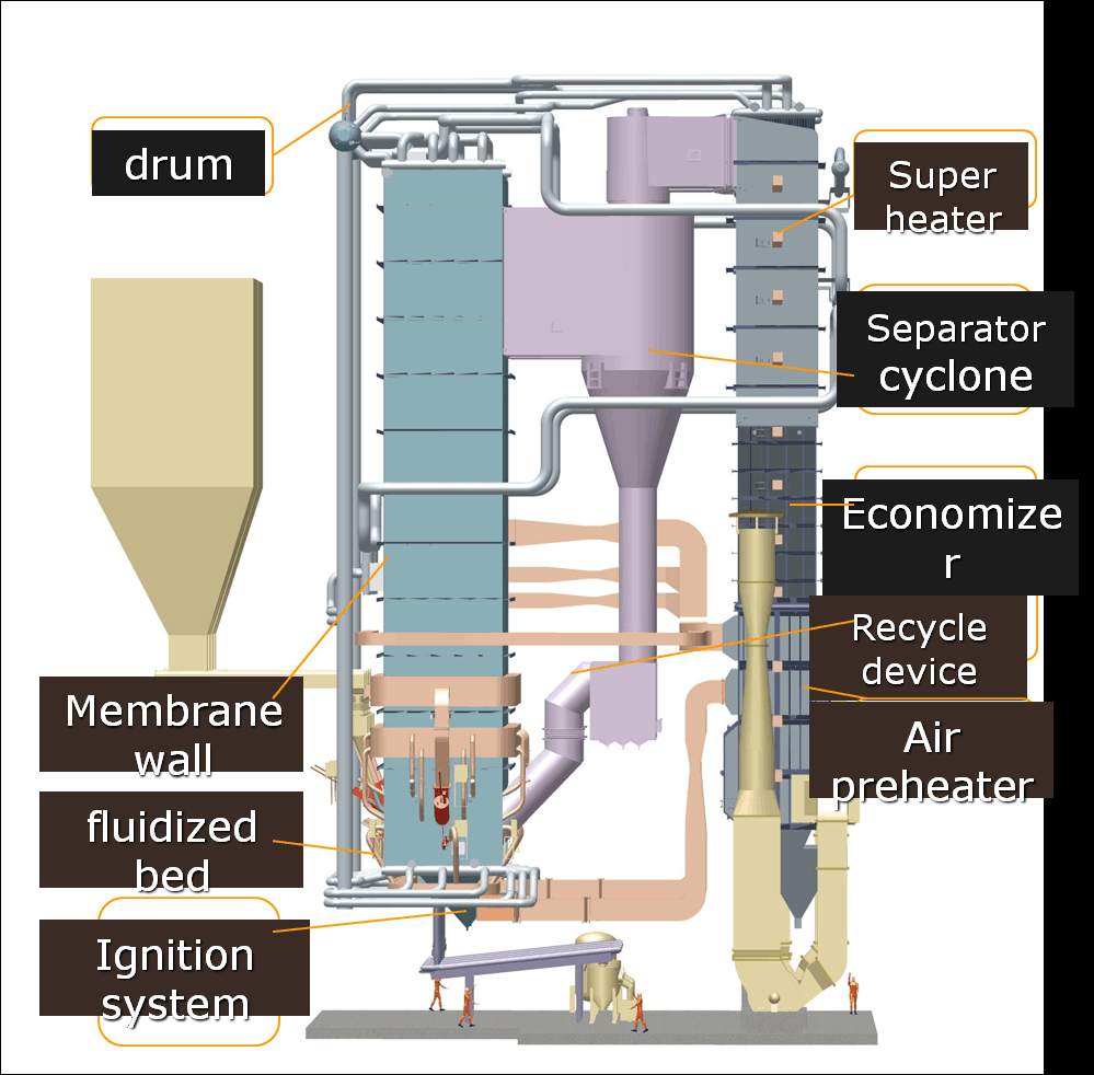
This is the section of a CFB datasheet that separates engineers who understand fluidized bed combustion from those who are just comparing heat output numbers. Every figure here is interconnected — get one wrong in the design and it cascades into poor combustion efficiency, excessive NOx, rapid refractory wear, or chronic load-following problems.
Bed Temperature: The 850–950°C Operating Window
The design bed temperature is usually stated as a single nominal value or a range, typically somewhere between 850°C and 950°C. That window is not arbitrary. Below roughly 850°C, carbon burnout efficiency falls off — you’ll see elevated CO in the flue gas and unburned carbon in the fly ash climbing past 3–5%, which hits fuel cost hard. Above 950°C, thermal NOx formation accelerates noticeably, and more critically for units using in-bed limestone injection, the calcination kinetics shift unfavorably: CaO sintering reduces the reactive surface area available for SO₂ capture, and your desulfurization efficiency can drop from 90%+ down to something considerably worse.
Check what the datasheet specifies as design bed temperature versus operating range. A well-designed unit running bituminous coal or petroleum coke typically targets 880–920°C. If you’re looking at a unit spec’d for high-moisture biomass or lignite and the stated bed temperature is 860°C, that’s defensible — the higher moisture content moderates furnace temperature naturally. But if the design calls for 940°C with high-sulfur coal and in-bed desulfurization, push back on the limestone consumption figures because they’re likely optimistic.
Primary Air / Secondary Air Ratio and Staged Combustion
Most CFB datasheets will state the PA/SA split, or you can derive it from the primary air flow and total combustion air figures. A typical well-staged design runs roughly 55–60% primary air (through the air distributor and into the dense bed) and 40–45% secondary air injected at one or two elevations above the bed. This staged arrangement creates a reducing zone in the lower furnace that suppresses NOx formation — it’s the main reason CFB units can achieve NOx figures of 50–150 mg/Nm³ without SCR, depending on fuel nitrogen content and furnace geometry.
If the datasheet shows a PA ratio of 70% or higher, that’s worth investigating. It can indicate a design optimized for a specific high-volatile fuel, or it may reflect a conservative approach to bed stability — but it will compromise NOx performance. Some budget designs skimp on secondary air ports to reduce wind-box complexity. You won’t see that stated explicitly anywhere; you have to infer it from the ratio.
Cyclone Separator Efficiency and Pressure Drop
The cyclone separator data block covers two numbers worth scrutinizing: collection efficiency and pressure drop. Collection efficiency for particles above 100 µm should be 99.5% or better in a properly designed high-temperature cyclone. Lower efficiency means reduced solid recirculation, which directly reduces combustion efficiency and bed temperature stability — the circulating inventory is both a heat carrier and an unreacted fuel buffer.
Pressure drop across the cyclone typically runs 800–1,500 Pa. Higher pressure drop generally correlates with better separation efficiency but increases ID fan power demand and accelerates refractory wear on the cyclone barrel. A unit showing a cyclone ΔP above 1,400 Pa deserves a question about refractory lining thickness and the expected maintenance interval — in practice, cyclone refractory in hard-duty service needs inspection every 8,000–12,000 operating hours, sometimes sooner with abrasive fuels like coal gangue.
CFB cyclone separators routinely achieve 99.5%+ collection efficiency for particles above 100 µm under design conditions.True
This is a well-established performance characteristic of high-efficiency CFB cyclones operating at design temperature and gas velocity, confirmed in open technical literature and manufacturer performance test reports.
Loop Seal and External Heat Exchanger Parameters
The loop seal (sometimes called the seal pot or J-valve) maintains the pressure seal between the cyclone return leg and the furnace while controlling solid circulation. The differential pressure across the loop seal — usually 3–8 kPa in standard designs — is a proxy for solid circulation rate. If the datasheet or technical specification lists solid circulation rate directly, typical values run roughly 15–40 kg/m²·s referenced to furnace cross-section, though this varies considerably with fuel and load.
Where an external heat exchanger (EHE) is included, look for the heat duty assigned to it. The EHE lets the designer route recirculating solids through an immersed bundle to absorb heat independently of the furnace, which gives real flexibility in superheater temperature control across load range. Units without an EHE rely more heavily on spray attemperators to control final steam temperature, which works but is less elegant and more prone to temperature cycling stress on headers. For plants operating at variable loads — cogeneration schemes, industrial steam users with batch processes — EHE presence on the datasheet is worth noting.
Fluidization Velocity: Back-Calculating from the Datasheet
The superficial gas velocity in the furnace — typically 4–6 m/s at full load — isn’t always stated directly, but you can back-calculate it. Take the total flue gas volumetric flow at furnace exit conditions (sometimes listed, sometimes derivable from fuel consumption and excess air ratio) and divide by the furnace cross-sectional area. If the result falls outside 4–6 m/s, something in the design geometry deserves a closer look. Below 4 m/s you risk defluidization; above 6 m/s erosion on the furnace walls and cyclone inlet accelerates, and particle residence time drops.
This back-calculation is a quick consistency check. I’ve seen datasheets where the stated furnace dimensions and the stated gas flow simply don’t reconcile — not necessarily fraud, but sometimes a sign the document was assembled from a template rather than sized from scratch for the specified fuel.
Bed Inventory and Startup Behavior
Bed material mass — the initial charge of silica sand or recirculated ash that fills the bottom of the furnace — is often buried in the technical specification rather than the summary datasheet. Typical bed inventory for a mid-sized unit (150–300 t/h steam) runs 20–60 tonnes, depending on furnace volume and design bed height. This matters operationally because a larger bed inventory means more thermal mass, which extends cold-start time (typically 4–8 hours from cold for most CFB units, against roughly 1–2 hours for a well-designed pulverized coal boiler) but also improves load-following stability once at temperature. Plants with frequent startups — waste heat recovery backup boilers, for instance — should check both the bed inventory and the design startup fuel consumption, because auxiliary burner fuel costs during heat-up are a real line item that datasheets rarely make obvious.
Emissions Guarantees — Reading NOx, SO2, Dust, and CO Limits Correctly
Emission figures are where datasheets cause the most confusion — and occasionally the most expensive surprises after commissioning. The number printed in the emissions block is meaningless without its reference conditions, and those conditions vary significantly between standards. Get this wrong and you may sign off on a boiler that passes its factory acceptance test but fails your local environmental permit on day one.
Reference Conditions Are Not Optional Fine Print
Every emission concentration on a CFB datasheet — NOx, SO2, particulate matter, CO — is normalized to a specific set of reference conditions: standard temperature and pressure (0°C, 101.325 kPa), dry flue gas basis, and a stated excess oxygen level. That last item is where the numbers diverge most dramatically.
Chinese GB 13271-2014 references emissions at 6% O₂ for solid fuel industrial boilers. The EU Industrial Emissions Directive (IED 2010/75/EU) references at 6% O₂ for solid fuel combustion plants above 50 MWth, but many European national permits and the World Bank IFC Performance Standard use 3% O₂ for certain plant categories. Converting between the two is straightforward mathematically, but easy to overlook when reviewing a Chinese-manufactured boiler datasheet for an EPC project in Southeast Asia or Sub-Saharan Africa.
A simple illustration: a CFB datasheet states NOx = 150 mg/Nm³ at 6% O₂. Converted to 3% O₂ reference, the same flue gas gives roughly 180–190 mg/Nm³ — a 20–25% increase, purely from reference correction. That difference can be the margin between permit compliance and a regulatory problem.
The same NOx emission value expressed at 6% O₂ will appear numerically higher when recalculated to 3% O₂ reference, because the flue gas is being expressed at a lower dilution baseline.True
The standard correction formula is: C_corrected = C_measured × (21 − O₂_ref) / (21 − O₂_measured). Shifting from 6% to 3% reference increases the reported concentration by a factor of (21−3)/(21−6) = 18/15 = 1.2, so a reading of 150 mg/Nm³ at 6% O₂ becomes 180 mg/Nm³ at 3% O₂.
How CFB Achieves Its NOx Without Post-Combustion Treatment
A well-designed CFB keeps NOx low through process control rather than flue gas treatment, which is one of its genuine advantages over pulverized coal firing. Air staging — splitting combustion air between primary air below the bed and secondary air injected higher in the furnace — reduces peak flame temperatures and limits thermal NOx formation. Bed temperature control, held in the 850–950°C range, simultaneously limits both thermal and fuel NOx pathways. In practice, a properly configured CFB should achieve NOx in the 100–200 mg/Nm³ range at 6% O₂ without selective catalytic reduction (SCR). Values closer to 50–80 mg/Nm³ are achievable with SNCR (urea or ammonia injection) added downstream.
When you review the datasheet, check whether the quoted NOx figure assumes any SNCR or SCR system. If the guarantee is ≤150 mg/Nm³ but the process flow diagram shows an SNCR skid, that treatment system needs to be confirmed in scope — and its reagent consumption should show up somewhere in the auxiliary utility table.
In-Bed Desulfurization — Three Numbers to Check
CFB’s desulfurization mechanism depends on injecting crushed limestone directly into the fluidized bed, where calcined CaO reacts with SO₂ at combustion temperature. The datasheet should state three things: the Ca/S molar ratio (typically 2.0–2.5 for 90–95% sulfur capture, though this depends heavily on fuel sulfur content and limestone reactivity), the limestone particle size specification (usually 0.1–1.0 mm — coarser material reduces surface area and capture efficiency, finer material increases elutriation losses and fan power), and the guaranteed SO₂ outlet concentration.
Cross-check the guaranteed SO₂ figure against your fuel’s actual sulfur content, not just the design fuel in the spec sheet. If your coal supply varies between 0.5% and 2.5% sulfur seasonally — which is common for imported coal blends — the limestone feed system needs to handle that range. A fixed Ca/S ratio guarantee at design sulfur content doesn’t protect you when sulfur spikes.
Also confirm whether a downstream wet or dry FGD system is included in the boiler island scope or treated as a separate package. Some datasheets quote an SO₂ figure that assumes both in-bed limestone injection and a secondary FGD absorber. If the FGD is a separate contract, the “boiler-only” SO₂ performance may be considerably higher.
Particulate Matter — Understand What’s Upstream of the Measurement Point
CFB combustion generates a heavy fly ash burden. Before the dust collector, flue gas leaving the furnace typically carries 20–40 g/Nm³ of particulates — that’s the raw loading the cyclone separators and then the ESP or baghouse must handle. The datasheet emission figure for particulate matter (dust) applies after the dust collection system, usually stating ≤30 mg/Nm³ or ≤50 mg/Nm³ depending on the applicable standard.
The critical procurement question is: whose scope does the dust collector fall under? It’s common in EPC projects for the boiler manufacturer to supply the boiler island including cyclone separators, while the ESP or baghouse is a separate contract with a different vendor. If that’s the arrangement, the boiler manufacturer cannot actually guarantee the final stack particulate figure — that guarantee belongs to the dust collector vendor. Make sure the datasheet and contract scope clearly delineate where the guarantee boundary sits.
CO as a Combustion Health Indicator
CO concentration in the flue gas tells you how completely the fuel is burning. A guarantee of CO 50 MWth) | World Bank IFC (3% O₂ equivalent, approx.) |
|—|—|—|—|—|
| NOx | 100–200 mg/Nm³ | 200 mg/Nm³ (new boilers) | 200 mg/Nm³ | ~200 mg/Nm³ (converted) |
| SO₂ | 100–400 mg/Nm³ | 300 mg/Nm³ (new, general area) | 150–400 mg/Nm³ (fuel-dependent) | 200 mg/Nm³ |
| Particulate matter | 20–50 mg/Nm³ | 30–50 mg/Nm³ | 20–30 mg/Nm³ | 50 mg/Nm³ |
| CO | <100 mg/Nm³ at MCR | Not specified in GB 13271 | 250 mg/Nm³ (some national permits vary) | Not separately specified |
Note: EU IED values shown are for solid biomass and coal co-firing plants; exact limits vary by plant capacity tier and member state permit conditions. Always verify the applicable standard against the host country’s transposed regulation — many African and Southeast Asian regulators apply World Bank IFC standards by default for new industrial projects with international financing.
The practical takeaway is to write the specific standard, oxygen reference level, and measurement basis into the purchase contract’s performance guarantee clause — not just the emission number itself. That single step eliminates most of the ambiguity that surfaces during commissioning and third-party stack testing.
Efficiency Figures — Boiler Thermal Efficiency, Heat Losses, and How Manufacturers Calculate Them
The efficiency number on a CFB datasheet is usually printed clearly — 91%, 92%, sometimes even 93% — and buyers treat it like a fixed fact. It isn’t. It’s a calculated result that depends heavily on methodology, fuel assumptions, and which system boundary the manufacturer drew when they ran the numbers. Two datasheets showing different efficiency figures may actually describe the same thermodynamic performance. Two showing identical figures may describe machines that will consume very different amounts of fuel in your plant.
LHV vs. HHV — the Invisible 5-Point Gap
Boiler thermal efficiency is the ratio of useful heat transferred to the working fluid divided by the heat released by the fuel. Simple enough. The problem is the denominator: manufacturers in China, continental Europe, and most Asian markets typically reference LHV (lower heating value), while North American practice under ASME standards references HHV (higher heating value). For a bituminous coal with moderate moisture, the difference is roughly 2–3 percentage points. For a high-moisture biomass blend — rice husks at 20–25% moisture, say — the gap can reach 5–6 points. A boiler quoted at 88% efficiency on an LHV basis is genuinely performing better than its figure suggests when compared against an 87% HHV-basis competitor. Always confirm which basis applies before any cross-vendor comparison. It should be stated in the datasheet’s boundary conditions block; if it isn’t, that’s itself a red flag worth raising before contract signature.
The Indirect Method and Its Five Loss Components
Most manufacturers calculate efficiency using the indirect (heat loss) method, which is what GB/T 10184 and ASME PTC 4 both prescribe. Rather than directly measuring output and input — which is practically difficult at scale — the method sums all identifiable losses and subtracts from 100%. The five standard loss terms are:
q2 (dry flue gas loss): Typically 5–7% for CFB units firing coal, depending on excess air ratio and flue gas exit temperature. Exit temperatures below 130°C are achievable with an economizer and air preheater in good condition; aging or fouled surfaces push this up fast.
q3 (hydrogen and moisture combustion loss): Ranges from roughly 0.5–1.5% for standard coal, climbing to 3–5% for wet biomass. The datasheet’s design fuel moisture directly determines this term.
q4 (unburned carbon in fly ash): For CFB boilers firing high-volatile coals or biomass, q4 typically falls in the 0.5–1.5% range. Firing low-volatile anthracite or high-ash coal, this loss can reach 3–5% or more. The carbon content in fly ash — usually expressed as LOI (loss on ignition) — should appear somewhere in the datasheet’s ash or combustion section. If a vendor quotes 92% efficiency on a low-volatile coal without showing an LOI figure below roughly 8%, scrutinize the calculation carefully.
q5 (unburned carbon in bottom ash): Usually 0.3–1.0% for well-designed CFB with proper bed inventory control. Higher with coarse fuel or poor air distribution.
q6 (radiation and convection loss): Small but not trivial on smaller units — typically 0.3–0.8%, decreasing as boiler size increases because surface-area-to-volume ratio improves.
Why CFB Unburned Carbon Losses Deserve Special Attention
Pulverized coal (PC) boilers grind fuel to 70–75 µm, which dramatically improves burnout. CFB runs coarser particle sizes — typically 0–10 mm — at bed temperatures of 850–950°C, and relies on cyclone recirculation to achieve acceptable carbon conversion. When the fuel is high-volatile (lignite, biomass, high-volatile bituminous), recirculation works well and total q4+q5 stays manageable. With low-volatile anthracite, char reactivity is low, recirculation efficiency is the only lever left, and vendors who haven’t designed the cyclone geometry carefully will deliver higher unburned losses than the datasheet promises. This is one of the few CFB-specific risks that doesn’t appear obviously in the headline efficiency number.
Net Efficiency vs. Boiler Island Efficiency
Some datasheets state boiler thermal efficiency only — that is, heat into steam divided by fuel input, with no fan or pump power accounted for. Others state net plant efficiency, which deducts the auxiliary power consumption of the primary air fan, secondary air fan, induced draft fan, and circulation pumps. For a CFB, auxiliary consumption typically runs 3–5% of gross output, dominated by the PA fan because CFB requires high-pressure primary air to fluidize the bed. A 91% boiler efficiency with 4% auxiliary deduction translates to roughly 87% net — a meaningful difference when you’re calculating annual fuel cost. Check the datasheet’s “system boundary” clause, and if it’s absent, ask the vendor to provide both figures explicitly.
What the Acceptance Test Protocol Actually Means
Most commercial datasheets reference either ASME PTC 4 or GB/T 10184 as the test method for the efficiency guarantee. Contractually, what matters is the tolerance band around the design fuel specification, the minimum test duration (usually 4–8 hours of steady-state operation per run), and what remedy applies if the measured efficiency falls short. A typical clause allows the measured fuel’s calorific value and ash content to deviate ±5% from the design fuel; outside that band, the vendor is entitled to recalculate the guaranteed efficiency accordingly. In practice, if the plant is receiving off-spec fuel regularly, the acceptance test result and the daily operational efficiency will diverge — sometimes significantly. Nailing down the test fuel specification during contract negotiation, rather than assuming the datasheet fuel is what will actually be burned on test day, saves a lot of arguments later.
CFB boiler thermal efficiency is always directly comparable across vendor datasheetsFalse
Efficiency figures depend on the calculation basis (LHV vs. HHV), the design fuel, the system boundary (boiler island vs. net plant), and the loss methodology used. Direct numerical comparison without normalizing these factors is unreliable.
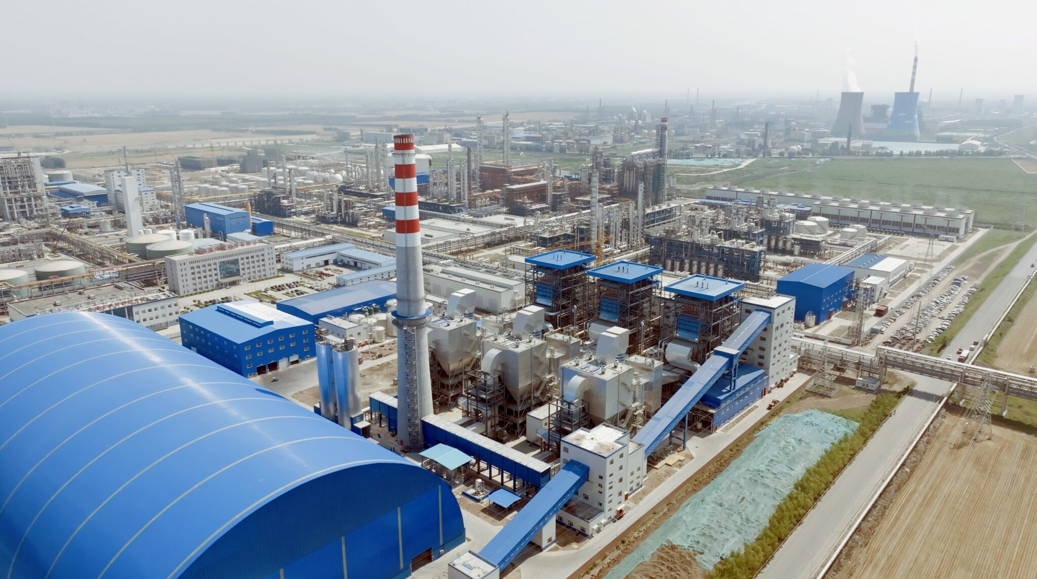
Auxiliary Equipment List and Scope of Supply — Mapping What Is and Is Not Included
The single most expensive procurement mistake on a CFB boiler project is signing a contract based on a headline price without methodically checking what that price actually covers. It happens more often than it should, even with experienced EPC teams. A datasheet from a Chinese manufacturer will often list a comprehensive-looking “scope of supply” block, but the boundary between included, optional, and buyer-furnished equipment is where the real cost exposure hides.
What a Standard Export CFB Package Typically Includes
Most Chinese CFB boiler manufacturers — supplying units in the 35–480 t/h range for export — will include the following as standard pressure parts and structural items: the steam drum and mud drum assembly, membrane waterwalls, superheater platens and finishing coils, the economizer bank, and the tubular or rotary air preheater. The cyclone separator body and the return leg (loop seal) are almost always included, because they are integral to CFB combustion physics and the manufacturer has to guarantee bed material circulation. Boiler structural steel — the buckstay system, boiler proper columns, platforms, and ladders — is usually in scope, though sometimes the foundation design is excluded and requires a local civil contractor. Refractory lining for the furnace lower zone, cyclone interior, and return leg is included by most suppliers, but the volume and specification vary; a dense-phase zone with SiC castable will cost more than a standard high-alumina brick lining, and you need to confirm which is actually specified.
The Long List of What Is Frequently Not Included
This is where procurement managers should slow down and read line by line. The induced draft fan, primary air fan, and secondary air fan are often listed as “by buyer” or quoted separately, even though they are operationally inseparable from the boiler. Same with the coal crusher and coal sizing screen. The fuel feeding system — drag chain conveyors, belt feeders, rotary airlocks, or pneumatic injection lances depending on fuel type — is almost always excluded from the boiler package price. Limestone handling and dosing equipment for in-furnace desulfurization is similarly orphaned in many contracts. The bottom ash cooler (water-cooled screw or fluidized bed type) is critical for continuous operation but routinely optional. Fly ash conveying — whether dense-phase pneumatic or mechanical drag chain to silos — is almost always a separate line item.
The flue gas cleaning boundary deserves special attention. The ESP or baghouse, any wet or dry FGD system, and the stack are typically outside the boiler manufacturer’s scope entirely. In an EPC contract this boundary needs to be assigned explicitly; if it falls between the boiler vendor and the balance-of-plant contractor without a clear owner, you will find out at commissioning, usually at 2–3× the original component cost.
Instrumentation, Control, and the DCS Integration Gap
A datasheet may show “BCS included” — boiler control system — but in practice this often means a standalone PLC panel covering burner management, bed temperature loops, and drum level, not full integration with the plant DCS. Ask specifically: what communication protocol does the BCS use? Modbus RTU is common on smaller units; Profibus DP or OPC-UA is more typical where plant DCS integration is expected. Getting this wrong means a parallel engineering effort during commissioning to build the interface, and that is neither cheap nor fast.
Spare Parts — The Items That Bite You at Startup
The first-fill spare parts list attached to the datasheet is worth reading carefully. Cyclone wear sleeves, bed drain valve internals, thermocouple assemblies (K-type, in multiple lengths for different bed zones), and refractory repair castable are the items procurement teams consistently forget to include in the initial contract. Ordering them at commissioning, freight-urgent, from overseas, routinely costs 3–5× the pre-order price. First-fill refractory alone — enough for one complete furnace lower zone repair — should be in the original contract if you can negotiate it.
Flue gas cleaning systems (ESP, baghouse, FGD) are included in a standard CFB boiler manufacturer's scope of supplyFalse
In nearly all export CFB boiler packages from Chinese manufacturers, the flue gas cleaning system and stack are outside the boiler pressure parts scope. They must be explicitly assigned to either the boiler vendor or the EPC/balance-of-plant contractor in the contract scope matrix.
CFB Auxiliary Equipment Scope Checklist
Use this table to audit any vendor’s scope document. Mark each item during technical clarification meetings before contract signature.
| Auxiliary Item | Typical Scope Status |
|---|---|
| Steam drum and mud drum | Included |
| Membrane waterwall panels | Included |
| Superheater coils (primary + finishing) | Included |
| Economizer bank | Included |
| Air preheater (tubular or rotary) | Included |
| Cyclone separator body | Included |
| Loop seal / return leg | Included |
| Boiler structural steel and platforms | Included |
| Furnace refractory lining | Included |
| Cyclone refractory lining | Included |
| Induced draft (ID) fan | Optional — confirm |
| Primary air (PA) fan | Optional — confirm |
| Secondary air (SA) fan | Optional — confirm |
| Coal crusher and screen | Excluded by default |
| Belt conveyor / drag chain feeder | Excluded by default |
| Rotary airlock feeders | Optional — confirm |
| Pneumatic fuel injection lances | Optional — confirm |
| Limestone storage silo | Excluded by default |
| Limestone dosing and injection system | Excluded by default |
| Bottom ash cooler (screw or fluid bed) | Optional — confirm |
| Bottom ash conveying system | Excluded by default |
| Fly ash conveying (pneumatic or mechanical) | Excluded by default |
| Fly ash silo | Excluded by default |
| Electrostatic precipitator (ESP) | Excluded by default |
| Baghouse filter | Excluded by default |
| Wet or dry FGD system | Excluded by default |
| Stack / chimney | Excluded by default |
| Boiler control system (BCS / BPCS) | Optional — confirm protocol |
| DCS integration and field instruments | Excluded by default |
| First-fill refractory and wear parts | Optional — negotiate in |
The practical discipline here is simple: take this list into every technical clarification session, go line by line with the vendor’s proposal engineer, and get written confirmation against each item. A scope gap found during that meeting costs nothing to fix. The same gap found during mechanical completion costs real money and real schedule.
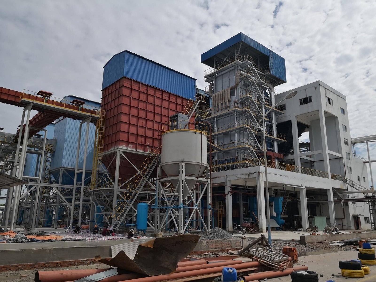
Design Codes, Material Standards, and Certification — What an International Buyer Must Verify
A datasheet that looks complete can still hide a compliance gap that will cost you months of re-engineering and potentially block equipment import entirely. Chinese CFB manufacturers work to a well-developed set of national standards, and those standards are genuinely rigorous — but they are not automatically equivalent to ASME, PED, or whatever local regulatory body governs your project site. Getting this sorted before contract award is infinitely cheaper than discovering the mismatch after the drums are already rolled.
Chinese Standards You Will See Referenced — and What They Actually Mean
GB/T 16507 is the core design standard for water-tube boilers in China, covering structural design, allowable stress tables, pressure part calculations, and hydrostatic test requirements. When a datasheet says “designed to GB/T 16507,” it means the pressure-part calculations used Chinese material allowable stresses and Chinese inspection protocols. For a domestic Chinese project this is perfectly fine. For export, it becomes the baseline you will need to map against the destination code.
TSG G0001 is the boiler safety technical regulation issued by China’s AQSIQ (now absorbed into SAMR). It governs manufacturing supervision, inspector qualification, and the type-approval system. An AQSIQ type-approval certificate on the datasheet tells you the design has been reviewed and approved for manufacture in China — it is not a substitute for third-country certification, but it does indicate the manufacturer is operating inside a formal regulatory framework rather than doing backyard fabrication.
NB/T 47002 covers clad plate materials used in pressure vessels and some boiler components. If your datasheet references clad drum shells or clad header sections, verify that this standard is cited alongside the parent plate standard.
Always ask the manufacturer to provide the actual certificate numbers, not just a list of standard names in a table. Any reputable shop will have these on file.
ASME Section I Certification for North American and ASME-Required Projects
If your project is in North America, or if your EPC contract specifies ASME compliance, the manufacturer must hold a current ASME S Stamp. This is not a document you can retrofit after fabrication. The S Stamp requires that the manufacturer’s quality system has been audited and accepted by ASME, and — critically — that an Authorized Inspector (AI) employed by a jurisdiction or insurance company accredited by the National Board witnesses hydrostatic testing and signs off on the data report (Form P-2 or P-3).
All pressure-retaining materials must be listed in ASME Section II. This means drum plate specified as GB 713 Q345R needs to be re-specified as SA-516 Gr.70 (a common and technically reasonable substitution, since the mechanical properties are close), and superheater tubes in high-temperature sections must shift from GB 5310 equivalents to SA-213 T91 or T22 depending on the temperature profile. This material re-specification is not trivial — it affects procurement lead time and cost, so factor 10–16 weeks for ASME-listed material procurement into your schedule, depending on the mill.
A manufacturer can apply an ASME S Stamp retrospectively to a boiler already fabricated to GB standardsFalse
ASME S Stamp certification requires Authorized Inspector witnessing during fabrication, including material traceability, fit-up inspection, and hydrostatic testing. Post-fabrication certification is not permitted under ASME Section I.
CE/PED Route for European, African, and Middle East Projects
The Pressure Equipment Directive 2014/68/EU applies directly within the EU and has been adopted as reference in many African and Middle Eastern procurement specifications, particularly on EPC projects with European financing. For a CFB boiler operating above the Category IV pressure-volume threshold — which almost every utility or industrial CFB will exceed — full conformity assessment with a Notified Body is mandatory.
This means the Notified Body (a TÜV, Bureau Veritas, SGS, or similar) must review design documents, witness production hold points, and issue an EC Declaration of Conformity. Boiler tube materials must carry EN 10216 certification (seamless tubes for pressure purposes), not just Chinese mill certificates. In practice, a Chinese manufacturer with European export experience will often stock dual-certified materials from mills that supply both GB and EN certificates — ask specifically whether the material certificates show EN designation.
Reading the Material Specification Table
The datasheet material table deserves a line-by-line review. Drum and steam drum header materials should be clearly stated — SA-516 Gr.70 or Q345R for moderate pressure; 15CrMoR or SA-387 Gr.11 for high-temperature high-pressure applications above roughly 450°C. Superheater outlet headers and final-stage superheater tubes in a unit operating above 540°C should reference T91 (9Cr-1Mo-V) or equivalent; if you see plain carbon steel specified for a 540°C superheater outlet, that is a design error worth flagging immediately.
Refractory lining specifications are often buried in an annex. Check castable density (typically 2.0–2.6 g/cm³ for heavy-duty furnace walls) and the service temperature rating — for CFB furnace lower zones, a minimum 1400°C-rated castable is normal. Cheaper datasheets sometimes list a generic “refractory lining” without density or service temperature, which tells you nothing about actual quality and opens the door to substitution during construction.
Weld Procedure and Welder Qualification
The technical specification — not just the datasheet summary — should explicitly reference the weld procedure qualification standard: ASME Section IX, EN ISO 15614-1, or both for dual-certified projects. Welder qualification records (WPQRs) should be available for audit. If the specification is silent on welding standards, treat that as a red flag. It does not necessarily mean the shop does poor welding, but it means quality oversight during fabrication will be harder to enforce contractually.
Seismic and Wind Load Design
This one gets overlooked surprisingly often. For projects in Southeast Asia, Latin America, or parts of the Middle East, seismic design is non-negotiable — but the standard Chinese boiler structural design does not automatically incorporate site-specific seismic loads. The boiler steel structure (columns, bracing, buckstays, platforms) needs to be designed to the applicable local code: IBC 2018 with ASCE 7 for US-influenced projects, IS 1893 for India, or the relevant national standard for your country.
Ask the manufacturer directly: “Have you applied seismic loads per [specific code] to the structural steel design?” If the answer is vague or the specification simply says “designed to local requirements” without showing the actual load case, push for a written confirmation with the design basis wind speed and seismic zone parameters filled in. Getting this wrong means either costly field reinforcement or, in a worst case, a structure that doesn’t pass local building authority review.
Frequently Asked Questions About CFB Boiler Datasheets and Technical Specifications
What is the difference between a CFB boiler datasheet and a technical specification?
A datasheet is the summary document — typically one to four pages — that states guaranteed performance numbers: steam flow, pressure, temperature, efficiency, emissions limits, and the design fuel. It is what gets attached to a quotation and what procurement managers review first. The technical specification is the full engineering package behind it, usually 50 to 200 pages depending on project complexity, covering the design basis, material selections, pressure part calculations, inspection and test requirements, refractory specs, auxiliary equipment interfaces, and operational limits. Signing a contract based only on the datasheet without reviewing the technical specification is a real procurement risk — the spec is where the conditions and exclusions live.
How do I know if the boiler efficiency on the datasheet is realistic?
Start by checking what fuel the efficiency is guaranteed on, and what feedwater temperature is assumed. A claim of 91–92% on a medium-rank bituminous coal with 10–12% moisture and 200°C feedwater temperature is credible. A claimed 94% on high-moisture biomass — say, 45–50% moisture — should trigger immediate scrutiny. Ask the vendor for the full heat loss breakdown: unburnt carbon loss, dry flue gas loss, radiation and convection loss, moisture loss. If they can’t produce it, the number is not a tested guarantee. Efficiency is calculated on LHV basis in almost all Chinese-manufactured CFB datasheets; if a European or North American comparison is needed, the LHV vs. HHV difference for coal is usually 1.5–3 percentage points and matters when comparing cross-vendor.
Can a CFB boiler designed to Chinese GB standards be used in my country?
Depends entirely on your local regulatory authority. Many countries — particularly in Southeast Asia, South Asia, and parts of Africa and the Middle East — accept GB-designed boilers with third-party inspection by an accredited body such as BV, TÜV, or Lloyd’s. Some require ASME Section I or PED 2014/68/EU requalification of the pressure parts, which changes material traceability requirements and documentation significantly and adds cost. Never assume acceptance. Verify with the local boiler inspection authority or your EPC contractor’s legal team before the contract is signed, not after the boiler ships.
What does “guaranteed at design coal” mean, and what happens if my coal changes?
Every performance guarantee — efficiency, steam output, emissions — is conditional on the fuel falling within the specified design range. Most contracts include a fuel deviation clause: if the as-fired coal deviates more than roughly ±10% in net calorific value or ±1 percentage point in sulfur content from the design coal, the manufacturer can formally revise the guarantees. In practice, coal supply variability is one of the most common sources of performance disputes. If you are sourcing coal from multiple origins or expect blend variability, push the vendor during negotiation to define a design coal range rather than a single point, and get written acknowledgment of performance across that range.
CFB boiler performance guarantees apply only to the stated design fuel specification.True
All thermal and emissions guarantees in a CFB boiler contract are conditional on the fuel being within the specified range; deviation triggers a contractual right to revise performance commitments.
Why does the CFB datasheet show two steam temperatures — saturated and superheated?
The saturated steam temperature is the drum outlet condition at the rated drum pressure — this is set by thermodynamics and does not depend on the superheater design. The superheated steam temperature is what comes out of the final superheater stage, which is what your turbine throttle valve or process header actually receives. A 130 t/h unit at 9.8 MPa might show 311°C saturated and 540°C superheated. The turbine connects at the superheated outlet. Mixing up these two temperatures when sizing a steam turbine or heat exchanger is a surprisingly common spec-reading error, particularly on translated documents.
How should I compare two CFB boiler datasheets from different manufacturers?
Headline efficiency numbers and price per ton of steam are almost meaningless without normalization. Build a side-by-side matrix and force every parameter to the same reference conditions: identical design fuel, same flue gas reference oxygen content (6% O₂ is the Chinese standard for coal-fired CFB; 11% O₂ is used in Europe — this alone shifts emission numbers dramatically), same feedwater inlet temperature, and same ambient air conditions. Check whether auxiliary power consumption is included in the efficiency calculation. One vendor quoting 92% efficiency while omitting 4.5% auxiliary consumption is not comparable to another quoting 90% net. The matrix approach makes these gaps visible and gives you a defensible basis for vendor selection.
Is the NOx figure on a CFB datasheet achievable without SCR?
Yes, in most cases. A well-designed CFB boiler operating at bed temperatures of 850–900°C with proper air staging — typically 40–60% primary air through the bed, secondary air injected above the dense phase — can achieve NOx in the range of 100–180 mg/Nm³ at 6% O₂ without any downstream treatment. The combustion mechanism in a CFB inherently suppresses thermal NOx compared to pulverized coal firing. However, if local regulations require NOx below 80–100 mg/Nm³, an SNCR (selective non-catalytic reduction, urea or ammonia injection) or full SCR system will be needed. That adds capital cost and operating reagent cost that must be included in the scope from the start. Do not assume SNCR is already in the quote unless it is explicitly listed in the scope of supply.
What spare parts should I request at the time of boiler purchase?
Negotiate first-fill spares into the initial contract. Minimum reasonable package: a complete set of cyclone wear-resistant liners (these are the first items to wear in high-ash fuels), refractory materials for one full re-lining, bed drain valve internals, all pressure part and flange gasket sets, one year’s supply of thermocouple assemblies across all measurement zones, and a set of critical instrument transmitters — differential pressure transmitters for the furnace and cyclone are the typical first failures. Emergency sourcing of proprietary refractory castables or custom wear liners from an overseas supplier during an unplanned outage can cost more in downtime than the entire spares package would have cost upfront. In my experience, plants that skip the spares negotiation almost always regret it within the first two operating years.
References
- BPVC Section I — Rules for Construction of Power Boilers — ASME
- Performance Test Codes — Fired Steam Generator Performance Testing — ASME
- Valmet CFB Boiler — Circulating Fluidized Bed Technology and Technical Features — Valmet
- PowerFluid Circulating Fluidized Bed Boilers — Fuel Flexibility and Steam Specifications — ANDRITZ
- Circulating Fluidized-Bed Boilers — IR-CFB Technology and Specifications — Babcock & Wilcox
- Boiler Efficiency and Combustion — Efficiency Calculations and Fuel Energy — Spirax Sarco
- Drum Boilers — Circulation Design and Steam Operating Parameters — Mitsubishi Power
- Metrological Traceability — Measurement Reliability and Calibration — National Institute of Standards and Technology
- Mining and Minerals — Coal Analysis and Fuel Characterization — Thermo Fisher Scientific
- Required Code Books — Power Boiler Construction and Certification Standards — ASME
How to Read a Circulating Fluidized Bed Boiler Datasheet and Technical Specification? Read More »