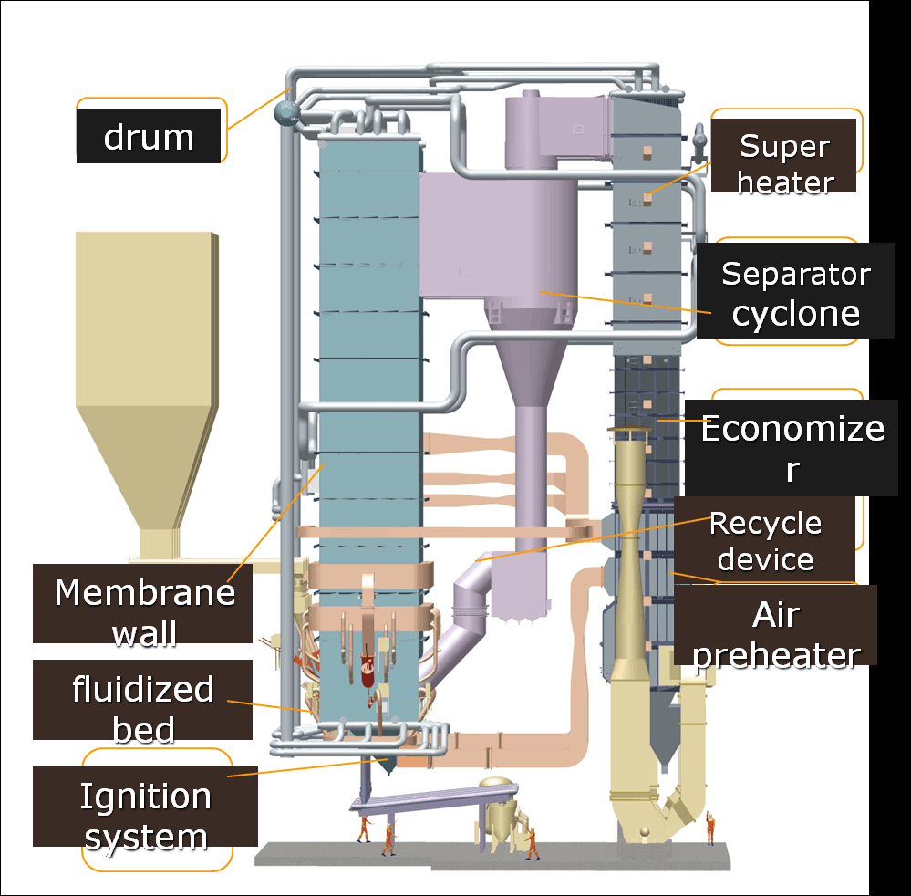
Circulating Fluidized Bed (CFB) boilers are known for their fuel flexibility, high efficiency, and low emissions, making them ideal for a wide range of industrial and utility-scale applications. However, selecting the correct capacity and size is not a one-size-fits-all process. Choosing the wrong size can lead to excess fuel consumption, poor load response, high emissions, or underperformance during peak demand. To optimize energy output and operational reliability, it’s crucial to understand what factors determine the right CFB boiler size for your facility.
The capacity and size of a Circulating Fluidized Bed (CFB) boiler you need depend on your plant’s steam or thermal load demand (measured in tons/hour or MW), the type and calorific value of fuel used, operating pressure and temperature, process continuity, and future scalability. Accurate sizing must account for peak load conditions, average consumption, load fluctuations, and combustion characteristics of multi-fuel inputs. Professional thermal load analysis ensures the CFB system is designed to meet real-world industrial demands while optimizing combustion efficiency and emissions control.
Let’s dive into the critical elements that influence proper CFB boiler sizing.
What process and load parameters determine the required capacity of a CFB boiler?
Circulating Fluidized Bed (CFB) boilers are favored for their fuel flexibility, efficient combustion at lower temperatures, and environmental advantages in industrial-scale steam and power generation. However, to fully realize their performance benefits, it’s essential to correctly size the boiler based on the process’s actual thermal requirements. This involves a detailed understanding of the facility’s steam or heat load profile, fuel properties, and operating conditions.
The required capacity of a CFB boiler is determined by a combination of process and load parameters including total steam or thermal energy demand, operating pressure and temperature, fuel type and calorific value, combustion efficiency, heat losses, load variability, and future expansion potential. These variables define how much fuel must be burned and how much heat must be recovered through the fluidized bed and heat exchange system to reliably meet operational requirements.
Below is a detailed exploration of each critical parameter influencing the sizing of a CFB boiler.
🔹 1. Steam or Thermal Load Demand
The primary sizing input is the total amount of steam or thermal energy required by the process or plant.
| Process Application | Typical Steam Load Range |
|---|---|
| Cement or steel manufacturing | 50–300 TPH |
| Power generation | 100–600 TPH |
| Chemical or refinery processes | 10–150 TPH |
| Pulp and paper production | 5–50 TPH |
Formula (Steam Load):
Total Steam Load (kg/h) = Sum of all connected process loads
Example:
Drying process: 6,000 kg/h
Turbine drive: 12,000 kg/h
Preheating units: 3,000 kg/h
Total Load = 21,000 kg/h = 21 TPH
🔹 2. Operating Pressure and Temperature
Higher pressures and temperatures increase steam enthalpy, requiring greater fuel input and heat exchange area.
| Pressure/Temp Class | Steam Enthalpy (kcal/kg) | Capacity Implication |
|---|---|---|
| Subcritical (<25 bar, <400°C) | ~660–720 kcal/kg | Standard |
| Superheated (30–60 bar, >450°C) | ~750–850 kcal/kg | Higher capacity needed |
| Ultra-supercritical (≥600°C) | 850+ kcal/kg | Requires precise combustion and heat transfer design |
The higher the enthalpy, the more energy per kg of steam is needed, increasing the required fuel throughput and combustion control complexity.
🔹 3. Fuel Type and Calorific Value
CFB boilers can burn a wide range of fuels, but fuel calorific value (CV) significantly impacts how much fuel is required to meet a given energy output.
| Fuel Type | Calorific Value (kcal/kg) | Impact on Sizing |
|---|---|---|
| Bituminous coal | 6,000–7,000 | Efficient, standard sizing |
| Lignite | 3,500–4,500 | Larger bed, more air, more volume |
| Biomass (wood chips) | 2,500–4,000 | Larger feeding and air systems |
| RDF (waste-derived fuel) | 2,000–4,500 | High variability, sizing buffer needed |
Low CV fuels = More kg/h of fuel = Larger boiler capacity required
🔹 4. Combustion Efficiency
CFB combustion efficiency depends on bed temperature, air distribution, and fuel type.
| Efficiency Range (%) | Factors Influencing Value |
|---|---|
| 85–95% | Depends on bed design, fuel prep, air control |
Lower efficiency → more fuel required → larger furnace and heat transfer area
Adjusted Heat Input = Required Heat Load ÷ Combustion Efficiency
🔹 5. System and Radiation Losses
Include 8–12% for:
Heat lost from boiler surfaces (radiation)
Blowdown, startup losses
Unburned carbon in ash
Total Output Requirement = (Steam Load × Enthalpy) × 1.10
🔹 6. Load Profile and Variability
CFB boilers can handle load fluctuations well, but sizing must consider:
| Load Characteristic | Sizing Strategy |
|---|---|
| Constant base load | Match closely to average + margin |
| Variable/batch process | Oversize or use accumulator |
| Peak load requirements | Include turndown or secondary units |
Turndown ratios in CFBs are typically 3:1 to 4:1, allowing safe operation from 30%–100% of capacity.
🔹 7. Future Expansion Potential
Allow for 10–30% margin if:
New product lines or operations are planned
Modular or multi-boiler configurations are anticipated
Long-term infrastructure strategy includes facility growth
Avoid costly retrofitting by preparing space and system scalability during initial design.
🔹 8. Environmental Controls
Sizing must accommodate:
SO₂ scrubbers
NOₓ reduction systems
ESP or baghouse filters
These systems:
Add draft losses
Require precise temperature control
May slightly reduce available heat transfer, requiring margin
🔹 Real-World Example: Cement Plant CFB Sizing
Steam Demand: 75 TPH
Pressure: 35 bar
Enthalpy: 740 kcal/kg
Required Output: 75 × 740 = 55,500,000 kcal/h
Fuel: Sub-bituminous coal @ 5,000 kcal/kg
Combustion Efficiency: 90%
Losses: 10%
Heat Input:
55,500,000 ÷ 0.90 × 1.10 = ~67.8 million kcal/h
Fuel Consumption = 67,800,000 ÷ 5,000 = 13,560 kg/h
Final Capacity: Select 80 TPH CFB boiler, including 7% expansion margin and ESP integration.
Summary: Key Parameters Driving CFB Boiler Capacity
| Parameter | Influence on Capacity Sizing |
|---|---|
| Steam/Thermal Load Demand | Sets baseline output requirement |
| Pressure and Temperature | Higher values = more enthalpy needed |
| Fuel Calorific Value | Lower CV = more fuel = larger combustion system |
| Combustion Efficiency | Adjusts input-output balance |
| System Losses | Adds 8–12% sizing buffer |
| Load Variability | Drives turndown needs and oversize margin |
| Environmental Controls | May reduce net heat output |
| Future Expansion | Margin added to support growth |
By thoroughly analyzing these process and load parameters, engineers can accurately size a CFB boiler that is fuel-efficient, load-responsive, emissions-compliant, and strategically scalable for long-term industrial demands.
How do you calculate thermal output and steam demand for CFB boiler sizing?
Correctly sizing a Circulating Fluidized Bed (CFB) boiler starts with calculating the required thermal output and steam demand. These two metrics form the foundation of the design—determining how much energy the boiler must supply and what fuel and system specifications are needed to deliver it efficiently. If calculated improperly, the boiler may be underpowered for critical operations or oversized, leading to poor efficiency and excessive costs.
Thermal output and steam demand for CFB boiler sizing are calculated based on process energy requirements, steam enthalpy, and fuel characteristics. First, determine the total steam flow needed to serve all processes at the desired pressure and temperature. Then multiply that by the enthalpy of the steam to calculate the required thermal output in kcal/h or MW. This thermal output is divided by the combustion efficiency and adjusted for system losses to determine the necessary fuel input and final boiler capacity.
Here’s a step-by-step breakdown to guide accurate CFB boiler sizing calculations.
🔹 Step 1: Determine Total Steam Demand
Identify all users of steam in the plant and calculate the total steam requirement.
| Process Application | Steam Load (Example) |
|---|---|
| Turbine Generator | 12,000 kg/h |
| Preheater & Dryer | 6,000 kg/h |
| Process Reactors | 5,000 kg/h |
| Misc. Heating | 2,000 kg/h |
| Total Steam Demand | 25,000 kg/h (25 TPH) |
🔹 Step 2: Determine Enthalpy of Steam (hₛ)
Enthalpy depends on the pressure and temperature of the steam.
| Operating Pressure | Temperature | Enthalpy (hₛ, kcal/kg) |
|---|---|---|
| 10 bar | Saturated | ~660 |
| 35 bar | Superheated | ~740 |
| 60 bar | Superheated | ~800 |
Use steam tables or Mollier diagrams for accurate enthalpy values.
Example:
Pressure = 35 bar, Steam enthalpy = 740 kcal/kg
🔹 Step 3: Calculate Required Thermal Output
Formula:
Thermal Output (kcal/h) = Steam Demand (kg/h) × Steam Enthalpy (kcal/kg)
Example:
25,000 kg/h × 740 kcal/kg = 18,500,000 kcal/h
Convert to other units if needed:
1 MW = 860,000 kcal/h
Thermal Output = 21.5 MW
🔹 Step 4: Adjust for Boiler Efficiency
CFB boilers typically have 85–92% efficiency.
Formula:
Heat Input Required = Thermal Output ÷ Combustion Efficiency
Assume 88% efficiency:
18,500,000 ÷ 0.88 = 21,022,727 kcal/h
🔹 Step 5: Add System Heat Loss Margin (8–12%)
Losses come from:
Radiation and convection
Blowdown
Startup purging
Ash unburned carbon
Add 10% for safety:
21,022,727 × 1.10 = 23,125,000 kcal/h
🔹 Step 6: Calculate Fuel Requirement Based on Calorific Value (CV)
| Fuel Type | CV (kcal/kg) |
|---|---|
| Bituminous Coal | 6,500 |
| Lignite | 4,000 |
| Biomass Pellets | 4,200 |
| RDF (Waste Fuel) | 2,500–4,500 |
Example (Bituminous Coal):
Fuel Required (kg/h) = Total Heat Input ÷ Calorific Value
= 23,125,000 ÷ 6,500 ≈ 3,558 kg/h
🔹 Step 7: Determine Final Boiler Capacity
Boiler size is typically expressed in TPH (tons per hour) for steam or MW for thermal load.
| Parameter | Value |
|---|---|
| Steam Load | 25,000 kg/h = 25 TPH |
| Thermal Output | 18.5 million kcal/h = 21.5 MW |
| Heat Input w/ Margin | ~23.1 million kcal/h |
| Fuel Requirement | ~3.56 tons/hour |
🔎 Select a CFB boiler rated at 25–30 TPH, with design margin for fuel variation or future expansion.
🔹 Summary: Boiler Sizing Calculation Flow
| Step | Formula or Action |
|---|---|
| 1. Total Steam Demand | Sum all kg/h usage |
| 2. Enthalpy of Steam | Use steam table (kcal/kg) |
| 3. Thermal Output (kcal/h) | Steam Load × Enthalpy |
| 4. Adjust for Efficiency | Thermal Output ÷ Efficiency |
| 5. Add Loss Margin (10%) | Heat Input × 1.10 |
| 6. Calculate Fuel Requirement | Adjusted Heat Input ÷ Fuel CV |
| 7. Final Sizing | Select TPH or MW based on adjusted demand |
Real-World CFB Boiler Sizing Example
Industry: Sugar Processing
Steam Load: 40 TPH
Steam Pressure: 40 bar (enthalpy ≈ 760 kcal/kg)
Fuel: Bagasse (CV = 2,200 kcal/kg)
Efficiency: 87%
Loss Margin: 10%
Step-by-step:
Thermal Output = 40,000 × 760 = 30.4 million kcal/h
Adjusted Input = 30.4 million ÷ 0.87 = 34.94 million kcal/h
With margin = 34.94 × 1.10 = 38.43 million kcal/h
Fuel required = 38.43 ÷ 2,200 = 17.47 tons/hour bagasse
Boiler selected: 42 TPH CFB boiler with biomass feeder and ash system
Final Takeaway
Accurate thermal and steam demand calculation is essential for correct CFB boiler sizing. By analyzing fuel type, process steam requirements, and operating conditions, you ensure a right-sized boiler that offers:
High combustion efficiency
Fuel flexibility
Reduced emissions
Long-term reliability
This technical approach guarantees that the boiler performs consistently and economically under all expected plant conditions.
What role does fuel type and calorific value play in determining boiler size?
Selecting the appropriate size for a CFB (Circulating Fluidized Bed) boiler is not only about matching steam demand or thermal load—it also heavily depends on the type of fuel used and its calorific value (CV). The characteristics of the fuel determine how much energy can be extracted per unit of mass, how much air is required for combustion, how much ash is generated, and how efficiently the energy can be transferred. Failing to factor in fuel type and calorific value during boiler design can lead to oversized systems, fuel inefficiency, frequent fouling, or even unstable combustion.
Fuel type and calorific value play a critical role in determining boiler size because the energy content (calorific value) of a fuel dictates how much fuel must be burned to meet a specific thermal or steam output. Low-calorific fuels require greater volumes and combustion capacity, leading to larger furnaces, fuel feeding systems, and ash handling setups. Different fuel types also affect combustion efficiency, ash content, fouling tendencies, and emissions, which influence the heat exchanger surface area and fluidization dynamics of the boiler.
Let’s explore in detail how these factors impact the design and sizing of a CFB boiler.
🔹 1. What is Calorific Value (CV)?
Calorific Value is the amount of energy (heat) released when one kilogram of fuel is completely burned. It is typically measured in kcal/kg, MJ/kg, or BTU/lb.
| Fuel Type | Calorific Value (kcal/kg) |
|---|---|
| Anthracite | 7,000–8,000 |
| Bituminous Coal | 6,000–7,200 |
| Sub-bituminous Coal | 5,000–6,000 |
| Lignite | 3,000–4,500 |
| Biomass (Wood Chips) | 2,000–4,200 |
| RDF (Waste Fuel) | 2,000–4,500 |
| Petcoke | 7,500–8,500 |
Higher CV = More energy per kg = Less fuel required
Lower CV = Less energy per kg = More fuel required → Bigger boiler
🔹 2. How Fuel CV Affects Boiler Sizing
To deliver a fixed amount of thermal energy, the required fuel input varies with its calorific value.
Example: Steam Demand = 30 TPH
Enthalpy of steam @ 40 bar = 740 kcal/kg
Thermal Output Needed = 30,000 × 740 = 22.2 million kcal/h
Assume combustion efficiency = 88%
Required Heat Input = 22.2 ÷ 0.88 = 25.2 million kcal/h
Fuel Requirement Calculation:
| Fuel Type | CV (kcal/kg) | Fuel Required (kg/h) |
|---|---|---|
| Bituminous Coal | 6,500 | 25,200,000 ÷ 6,500 ≈ 3,877 kg/h |
| Lignite | 4,000 | 25,200,000 ÷ 4,000 ≈ 6,300 kg/h |
| Biomass Pellets | 3,500 | 25,200,000 ÷ 3,500 ≈ 7,200 kg/h |
| RDF | 2,500 | 25,200,000 ÷ 2,500 ≈ 10,080 kg/h |
🔸 Design Implications of Low CV Fuels:
Larger fuel feeding systems
Bigger combustion chamber
Higher air volume and fan power
Increased flue gas volume
More ash removal capacity
🔹 3. Fuel Type Impact on Boiler Components
Each fuel type affects key boiler design elements beyond just energy content:
| Design Element | Impact of Fuel Type |
|---|---|
| Combustion Chamber | Lower CV fuels require larger volume |
| Fuel Feeder | Needs higher throughput for low-CV fuels |
| Air Distributor | Must be tuned for volatile vs dense fuels |
| Cyclone Separator | Ash quantity and particle size influence efficiency |
| Ash Handling System | High ash fuels require larger and faster ash systems |
| Heat Exchange Surfaces | Biomass and RDF tend to foul more frequently |
🔹 4. Fuel Blending and Flexibility in CFB Design
One of the strengths of CFB technology is multi-fuel capability. However, this requires:
Sizing for the lowest CV fuel expected in the mix
Designing air distribution and bed temperatures to accommodate variable volatiles
Tuning cyclone separators and heat exchangers for slag and ash variability
Example:
A cement plant using 70% petcoke (high CV) + 30% RDF (low CV) must size the boiler to handle peak RDF volume, even if the average calorific input is higher.
🔹 5. Emissions and Combustion Efficiency
Different fuels release different emission profiles and impact combustion completeness.
| Fuel Type | Combustion Challenges |
|---|---|
| Biomass | High moisture → incomplete burn |
| RDF | Inconsistent composition |
| Petcoke | High sulfur → more SO₂ scrubbing |
| Lignite | High ash → fouling and clinkers |
Boiler sizing must accommodate:
Larger flue gas handling system
SO₂ scrubber or desulfurization units
Dust collectors and ESPs
🔹 6. Real-World Example: Multi-Fuel CFB Boiler
Industrial Paper Mill
Required Steam Load: 40 TPH
Fuel: 60% biomass (CV = 3,500 kcal/kg), 40% coal (CV = 6,000 kcal/kg)
Average CV = (0.6 × 3,500) + (0.4 × 6,000) = 4,500 kcal/kg
Heat Input:
40,000 × 740 = 29.6 million kcal/h ÷ 0.88 = 33.6 million kcal/h
Fuel Needed = 33.6 ÷ 4,500 = 7,467 kg/h
Sizing Notes:
Combustion chamber sized for biomass fuel volume
Feeders and cyclones sized for highest expected ash loading
Air system designed with variable control dampers for fuel flexibility
Summary: How Fuel Type and Calorific Value Affect Boiler Size
| Factor | High CV Fuel (e.g., coal, petcoke) | Low CV Fuel (e.g., biomass, RDF) |
|---|---|---|
| Fuel Volume | Lower | Higher |
| Furnace Size | Smaller | Larger |
| Feeding System | Lower throughput | High-capacity conveyors/hoppers |
| Airflow Requirements | Moderate | Higher (for volatiles & moisture) |
| Ash Generation | Moderate | High (esp. for RDF, lignite) |
| Boiler Efficiency Impact | Stable | More fluctuation |
By carefully considering fuel type and calorific value, boiler designers can ensure that the CFB system is correctly sized, capable of maintaining combustion efficiency, handling ash and emissions, and operating reliably across its intended fuel range. This leads to improved fuel economy, lower emissions, and long-term plant resilience.
How do pressure and temperature specifications affect the boiler’s design capacity?
When designing or sizing a CFB (Circulating Fluidized Bed) boiler, engineers must consider not only the amount of steam required but also the pressure and temperature at which that steam must be delivered. These parameters significantly influence the enthalpy of the steam, the energy transfer efficiency, and the mechanical design of the boiler’s critical components. Misjudging them can result in incorrect capacity sizing, material failure, or non-compliance with safety regulations.
Pressure and temperature specifications affect the boiler’s design capacity by determining the enthalpy of the steam output, which directly influences the total thermal energy required to meet process demands. Higher pressure and temperature levels increase the energy content per kilogram of steam, requiring more fuel input, larger and stronger pressure vessels, enhanced heat exchanger surfaces, and high-grade materials. These factors lead to higher design capacity requirements and affect the boiler’s efficiency, durability, and cost.
Here’s a detailed breakdown of how and why pressure and temperature matter in boiler sizing.
🔹 1. Understanding Enthalpy and Its Role in Capacity
Enthalpy (h) is the total energy content of steam, which increases with pressure and temperature. The higher the steam enthalpy, the more thermal input is required to produce each kilogram of steam.
| Steam Condition | Pressure (bar) | Temp (°C) | Enthalpy (kcal/kg) |
|---|---|---|---|
| Saturated | 10 | ~184 | ~660 |
| Superheated | 35 | ~450 | ~740 |
| High Superheated | 60 | ~500 | ~800 |
| Ultra-supercritical | 250+ | >600 | >860 |
🔸 Impact on Sizing:
If your process requires steam at 740 kcal/kg (35 bar) instead of 660 kcal/kg (10 bar), you’ll need:
More energy per kg of steam
More fuel input
Higher heat transfer surface area
A larger combustion and recirculation system
🔹 2. Higher Thermal Output = Higher Fuel Input
Formula:
Required Thermal Output = Steam Demand × Enthalpy
Example:
Steam Demand: 40 TPH
Enthalpy at 10 bar: 660 kcal/kg → Thermal Output = 26.4 million kcal/h
Enthalpy at 35 bar: 740 kcal/kg → Thermal Output = 29.6 million kcal/h
Increase = ~12% more energy needed
This leads to:
More fuel per hour
Larger furnace volume
Bigger feed and air systems
🔹 3. Boiler Drum and Pressure Parts Design
As pressure increases, so does the mechanical stress on the boiler drum, waterwalls, and headers.
| Pressure Class | Design Implication |
|---|---|
| <25 bar (Subcritical) | Mild steel shell, standard drum size |
| 25–60 bar (High) | Thicker drum walls, forged headers |
| >100 bar (Supercritical) | No drum (once-through), high alloy steel |
At higher pressures:
Drum size increases to withstand force
Materials must meet ASME and EN standards for creep and fatigue
Weld joints and inspections become more complex
🔹 4. Temperature Effects on Heat Exchangers and Surfaces
Superheating the steam requires additional surface area to elevate temperature beyond saturation.
| Temp Range | Design Impact |
|---|---|
| Up to 350°C | Minimal, may not need separate superheater |
| 350–450°C | Needs superheater coils, finned surfaces |
| 450–600°C | Requires high alloy tubes (e.g., Inconel) |
| >600°C | Advanced metallurgy and staged heat exchange |
These surfaces must be:
Corrosion and erosion resistant
Protected from slagging and fouling
Designed for precise temperature control (especially in CFBs)
🔹 5. Fuel Input and Combustion Efficiency Adjustments
To achieve higher enthalpy levels:
Bed temperature must be carefully controlled (820–900°C typical for CFB)
Air/fuel ratio must be optimized to sustain higher combustion rates
Cyclone and recirculation systems must support higher flow velocities
Low-quality fuels (e.g., biomass, RDF) complicate this because:
They have higher moisture
More air is needed, which increases fan size and power
Fluctuating combustion affects superheater performance
🔹 6. Emissions and Control Considerations
Higher temperatures and pressures often mean:
More NOₓ formation (needs better staged combustion or SCR)
Tighter emissions regulation compliance
Need for precise automated controls (feed rate, oxygen trim, flue gas recirculation)
These systems must be sized and integrated into the boiler design, affecting overall capacity requirements.
🔹 7. Real-World Example: Steel Mill CFB Boiler
Steam Requirement: 60 TPH
Option A: 10 bar saturated → Enthalpy = 660 kcal/kg → 39.6 million kcal/h
Option B: 35 bar superheated → Enthalpy = 740 kcal/kg → 44.4 million kcal/h
Combustion Efficiency: 88%
Heat Input with 10% loss margin:
A: 39.6 ÷ 0.88 × 1.10 ≈ 49.5 million kcal/h
B: 44.4 ÷ 0.88 × 1.10 ≈ 55.5 million kcal/h
Result:
Boiler B must deliver 12% more heat, use more fuel, and incorporate stronger pressure parts and larger heat exchangers.
Summary: Pressure & Temperature Effect on Boiler Design Capacity
| Factor | Higher Pressure/Temperature Effect |
|---|---|
| Steam Enthalpy | Increases thermal energy per kg |
| Fuel Consumption | Rises to meet higher output |
| Boiler Size | Larger furnace, heat exchanger, and piping |
| Material Requirements | Stronger, heat- and corrosion-resistant alloys |
| Efficiency & Control Complexity | More precise automation required |
| Cost and Maintenance | Higher due to complexity and material stress |
Accurately accounting for pressure and temperature specifications during CFB boiler sizing ensures that the system can reliably meet process energy demands, withstand mechanical and thermal stress, and maintain long-term efficiency and safety under high-performance operating conditions.
Why is load variation and turndown ratio critical in sizing a CFB system?
In real-world industrial operations, steam demand is rarely constant. Processes often fluctuate across daily, weekly, or seasonal cycles—making it essential for boiler systems to adapt efficiently to changing load conditions. The turndown ratio, which reflects how much a boiler can reduce output below its maximum capacity while still maintaining stable and efficient operation, becomes a vital design parameter. In a Circulating Fluidized Bed (CFB) system—known for fuel flexibility and steady combustion—load adaptability is particularly important due to the complexity of the fluidized bed dynamics, air distribution, and combustion temperature control.
Load variation and turndown ratio are critical in sizing a CFB system because they determine the boiler’s ability to operate efficiently, safely, and responsively under part-load conditions. A properly sized CFB boiler with an adequate turndown ratio can handle fluctuating demand without cycling, fuel waste, or combustion instability. This ensures consistent steam supply, stable bed temperatures, reduced emissions, and prolonged equipment life. Failure to account for load variation can result in oversizing, poor part-load efficiency, or inability to track demand changes.
Let’s explore in detail why these two factors are so central to effective CFB boiler sizing and operation.
🔹 1. What Is Load Variation?
Load variation refers to the fluctuations in steam or thermal demand over time. It can be caused by:
Shift changes or production cycles
Batch vs. continuous processes
Seasonal temperature changes (e.g., heating loads)
Startup, idle, and shutdown events
| Time Period | Steam Load (Example) |
|---|---|
| Day shift (full load) | 100% (e.g., 30 TPH) |
| Night shift | 50–60% (e.g., 15–18 TPH) |
| Weekend/low demand | 25–40% (e.g., 7–12 TPH) |
🔍 Without flexibility, the boiler wastes energy or fails to meet minimum demand.
🔹 2. What Is Turndown Ratio?
Turndown Ratio = Maximum Capacity ÷ Minimum Stable Capacity
It defines how much the boiler can reduce its output while maintaining:
Stable bed fluidization
Complete combustion
Acceptable flue gas emissions
Mechanical integrity of ash and heat exchange systems
| Boiler Type | Typical Turndown Ratio |
|---|---|
| Traditional Coal | 2:1 to 3:1 |
| Modern CFB | 3:1 to 5:1 |
| Modular Systems | 10:1+ (combined units) |
Example:
A 50 TPH CFB boiler with a 4:1 turndown ratio can stably operate down to 12.5 TPH.
🔹 3. Why It Matters in Sizing Decisions
✔️ A. Avoiding Over-Sizing
If the boiler is sized only for peak demand (e.g., 50 TPH) but regularly runs at 20 TPH, it will:
Cycle frequently
Suffer from poor combustion
Experience reduced heat transfer
Accelerate wear on fans, valves, feeders
✅ Designing with load variation in mind ensures the unit runs within its optimal efficiency band most of the time.
✔️ B. Handling Low Load Conditions
At low loads:
Bed temperature may drop below ideal (850–900°C), leading to incomplete combustion
Air velocity may fall below fluidization threshold
Pressure control becomes unstable
Boiler design must include:
Adaptive air systems
Fuel feed modulation
Bed material recycling control
🔹 4. Impact on Fuel Efficiency and Emissions
At part-load, improper turndown results in:
Excess unburned carbon
High CO and NOₓ emissions
Poor ESP and baghouse effectiveness due to flue gas cooling
Reduced boiler efficiency (drops from 90% to <75%)
| Load (% of Full) | Efficiency in Poor Design | Efficiency in High Turndown Design |
|---|---|---|
| 100% | 90% | 90% |
| 60% | 75–80% | 87% |
| 30% | <70%, cycling risk | 85% |
🔹 5. Design Solutions for Load Variability in CFBs
| Strategy | Benefit |
|---|---|
| High turndown air distribution | Maintains bed fluidization at low loads |
| Bed material recirculation tuning | Prevents temperature drop, improves combustion |
| Dual fuel capability | Switch to high CV fuel during low load |
| Modular (N+1) boiler setups | One unit runs full load while others shut down |
| Intelligent control systems | Optimize airflow, fuel rate, bed temp automatically |
🔹 6. Real-World Example: Textile Mill CFB Sizing
Peak Steam Load: 25 TPH
Normal Operation: 15–20 TPH
Weekend Load: 8 TPH
Solution 1:
25 TPH single boiler, 3:1 turndown → Minimum load = 8.3 TPH
Just covers weekend load, but part-load efficiency suffers
Solution 2:
2 × 12.5 TPH modular CFBs → Use one unit at 8–12 TPH, both at peak
High efficiency at all load conditions, simplified maintenance, redundancy
🔹 7. CFB-Specific Considerations
| CFB Feature | Load/Turndown Design Requirement |
|---|---|
| Fluidization stability | Maintain air velocity > minimum (1.5–2.0 m/s) |
| Bed temperature | Keep within 850–900°C for efficient sulfur capture |
| Ash handling rate | Scale with combustion rate to avoid accumulation |
| Cyclone performance | Adjust for velocity and particle load changes |
Summary: Why Load Variation & Turndown Ratio Are Critical
| Design Factor | Without Turndown Consideration | With Proper Turndown Design |
|---|---|---|
| Efficiency at Part Load | Drops sharply (<70%) | Maintained above 85% |
| Combustion Stability | Incomplete, high CO/NOₓ | Clean, complete burn |
| Boiler Longevity | Increased cycling, mechanical wear | Steady operation, longer life |
| Fuel Cost per TPH | Increases due to losses | Lower due to optimized combustion |
| Flexibility | Poor, rigid operation | Dynamic, load-responsive system |
Designing a CFB boiler to accommodate load variation and ensuring a sufficient turndown ratio is key to maintaining system stability, emissions compliance, and cost-effective operation throughout the boiler’s lifecycle. It ensures the unit can respond to real-world demands, not just theoretical peak conditions.
What space, emissions, and expansion factors should be considered in design sizing?
When designing and sizing a Circulating Fluidized Bed (CFB) boiler system, it’s not enough to focus solely on thermal or steam output. Real-world implementation requires a broader lens—one that incorporates physical space limitations, emissions control requirements, and future scalability. Neglecting these considerations at the design stage can lead to project delays, non-compliance penalties, safety risks, and prohibitively expensive retrofits. Instead, integrating space, emissions, and expansion factors into initial boiler sizing ensures long-term operational, regulatory, and economic success.
Space availability, emissions control infrastructure, and future expansion potential significantly influence CFB boiler design sizing. Space considerations determine boiler footprint, access for maintenance, ash handling, and flue gas routing. Emissions regulations shape the size and complexity of scrubbers, ESPs, and gas treatment systems. Expansion planning impacts layout, utility oversizing, and the ability to add boilers or auxiliaries in the future. These factors ensure the system remains compliant, maintainable, and scalable for future growth.
Here’s a detailed breakdown of each factor category and its effect on boiler design and sizing.
🔹 1. Space and Layout Considerations
CFB boilers require more space than many other types due to their circulation loops, cyclone separators, fluidization chambers, and ash removal systems.
🔸 A. Boiler Footprint and Height
| Component | Typical Space Requirement |
|---|---|
| Furnace + Windbox | 6–10 m × 4–6 m × 20+ m tall |
| Cyclone Separator | 4–6 m diameter × 10–15 m tall |
| Heat Exchangers (Economizer, SH) | 4–8 m length |
| Ash Handling Units | 3–6 m² area with bottom clearance |
Footprint depends on:
Fuel type (e.g., biomass needs larger bed area)
Capacity (bigger output = taller furnace and larger cyclones)
Whether components are horizontal or vertical
🔸 B. Installation and Maintenance Access
| Clearance Area | Minimum Recommended Distance |
|---|---|
| Front (control/burner zone) | 2.0 m |
| Side walls (access panels) | 1.0–1.5 m |
| Top (lifting/rigging space) | 3.0 m+ |
| Walkways around ash system | 1.2–1.5 m |
⚠️ Inadequate clearance = service difficulty, safety hazards, and regulatory issues
🔸 C. Structural Considerations
CFB units may weigh 50–300 metric tons, especially when filled with bed material
Require reinforced foundations and vibration damping
Multi-level platforms must support human access + component loading
🔹 2. Emissions Control Requirements
As environmental regulations become more stringent, emissions equipment can rival the boiler itself in size and complexity.
🔸 A. Types of Emissions to Manage
| Emission Type | Typical Control Equipment |
|---|---|
| SO₂ | Limestone injection + Wet/Dry FGD systems |
| NOₓ | Low-NOₓ staging, Selective Non-Catalytic Reduction (SNCR), SCR |
| Particulate | Electrostatic Precipitator (ESP), Baghouse filter |
| CO | Air-fuel ratio control + burner tuning |
🔸 B. Sizing Impact of Emissions Systems
| System | Design Implications |
|---|---|
| ESP/Baghouse | Requires large horizontal or vertical volume |
| SCR Reactor | Needs precise temperature zone (e.g., 300°C) |
| FGD Unit | Separate building or tank footprint |
Layout must allow for:
Ductwork routing from boiler outlet to emissions unit
Access for inspections and filter bag changes
Stack height to meet dispersion regulations (often >30 m)
🔹 3. Future Expansion and Scalability
Long-term planning must anticipate growth in demand, production lines, or energy integration (e.g., cogeneration or district heating).
🔸 A. Physical Layout for Expansion
| Element | Expansion Planning Requirement |
|---|---|
| Space for Extra Boiler Unit | Leave 25–40% floor space in boiler house |
| Oversized Steam Header | Stub ports for future connections |
| Fuel Handling Infrastructure | Add capacity in conveyors, bunkers |
| Ash Handling & ESP Sizing | Design with modular sections or future bins |
| Chimney Stack & Ducting | Sized for combined flue volumes |
🔸 B. Utilities and Control System Scalability
PLC or DCS systems should include spare I/O channels
Water softening units, blowdown tanks, and deaerators should be oversized or duplicated
SCADA software should support multi-unit monitoring
✅ These decisions save millions in retrofits and prevent months of downtime later.
🔹 Real-World Example: Waste-to-Energy Plant (CFB Boiler)
Initial Steam Demand: 50 TPH
Fuel: Mixed RDF and biomass
Space Available: 50 m × 25 m × 35 m
Expansion Plan: Add 30 TPH within 5 years
Design Actions Taken:
Boiler sized at 55 TPH with 4:1 turndown
ESP and FGD area reserved for second unit
Chimney designed with dual flue liner
Fuel conveyor capacity oversized by 50%
Control system programmed for 2-boiler interface
Result:
Phase 2 boiler added with no structural changes
$420,000 saved in civil and utility retrofit costs
Seamless integration, no process disruption
Summary: Space, Emissions & Expansion in Boiler Design Sizing
| Factor Category | Key Considerations | Sizing Impact |
|---|---|---|
| Space/Footprint | Floor area, height, access, structural load | Determines max boiler dimensions & layout options |
| Emissions Control | ESP, SCR, FGD equipment sizing and ductwork | Adds volume and affects flue routing & thermal profile |
| Expansion Planning | Spare capacity, future boiler slots, modular headers | Reduces future capex and avoids layout conflict |
Considering space availability, emissions infrastructure, and future scalability during boiler design sizing enables a project that is physically feasible, environmentally compliant, and future-ready—leading to more efficient operations, safer workspaces, and better ROI across the lifecycle of the boiler system.
🔍 Conclusion
Properly sizing a Circulating Fluidized Bed boiler is essential to achieving operational efficiency, fuel savings, and emissions compliance. By evaluating real-time process needs, fuel characteristics, and growth potential, you can choose a boiler capacity that not only meets current demands but also adapts to future load shifts. With the right design and sizing strategy, your CFB boiler can deliver maximum performance, flexible fuel utilization, and long-term reliability.
📞 Contact Us
💡 Need expert help in sizing your CFB boiler? Our engineering team specializes in customized load analysis and system design for CFB boilers across various industrial applications.
🔹 Reach out now for a tailored CFB boiler sizing consultation that ensures performance, flexibility, and efficiency! 🔄🔥📊
FAQ
How is the capacity of a circulating fluidized bed (CFB) boiler calculated?
CFB boiler capacity is calculated based on the required steam output or heat load, typically measured in tons per hour (TPH) or million BTU/hr. It must match peak industrial demand while allowing for fuel variability and load changes.
What is the typical capacity range for CFB boilers?
CFB boilers are available in a wide range, from 10 TPH to over 300 TPH for steam generation, and from 20 to 1000+ million BTU/hr for hot water or thermal fluid systems, depending on application scale.
What factors influence the size of a CFB boiler?
Sizing depends on steam pressure and temperature requirements, type and calorific value of fuel, load fluctuations, efficiency targets, combustion system design, and emission compliance needs.
Why is correct sizing important for CFB boilers?
Oversized boilers increase capital and operational costs, while undersized systems can’t handle variable fuel loads or demand spikes. Proper sizing ensures combustion stability, energy efficiency, and long-term reliability.
Can CFB boilers be customized to specific industry needs?
Yes. CFB boilers are highly customizable based on fuel types (coal, biomass, petcoke), ash content, footprint constraints, redundancy needs, and environmental regulations. Custom engineering ensures optimized performance.
References
CFB Boiler Design and Sizing Guide – https://www.energy.gov
Circulating Fluidized Bed Combustion Explained – https://www.sciencedirect.com
CFB Boiler Capacity & Efficiency – https://www.researchgate.net
Boiler Sizing for Industrial Applications – https://www.bioenergyconsult.com
Steam Load Calculation for Boilers – https://www.epa.gov
Fuel Flexibility in CFB Boilers – https://www.mdpi.com
Right-Sizing CFB for Power and Industry – https://www.iea.org
Advanced CFB Boiler Design Trends – https://www.energysavingtrust.org.uk
Industrial Boiler Selection & Design – https://www.automation.com
Boiler Pressure & Capacity Matching – https://www.sciencedirect.com
