Retrofitting a new boiler into a site that already has a turbine skid or a heat recovery loop is rarely as straightforward as the equipment salesperson implies. Pressure mismatches, steam quality gaps, and control philosophy conflicts can turn what looks like a clean integration on paper into months of unplanned downtime, repeated commissioning visits, and turbine trips that your maintenance team starts blaming on the boiler — sometimes correctly, sometimes not. Get the interconnection wrong and you are not just looking at efficiency losses; you are risking turbine blade erosion from wet steam, heat exchanger fouling that compounds across seasons, and regulatory headaches when your combined emissions picture no longer matches what was permitted.
Yes, a power plant boiler can be integrated with existing turbine or heat recovery systems, provided steam pressure, temperature, and flow characteristics are matched to the turbine’s inlet requirements — typically 1.3–4.0 MPa for back-pressure units and 4.0–13.7 MPa for condensing configurations. A well-executed integration using a CHP arrangement with a back-pressure turbine routinely achieves overall thermal efficiencies of 75–90%, roughly double what a power-only cycle delivers. The engineering work required spans P&ID alignment, control interlock design, and flue-gas recovery staging, but it is entirely achievable within a structured EPC timeline.
What makes this question genuinely interesting — and what most generic guides skip entirely — is that the answer changes depending on whether you are integrating with a gas turbine exhaust system, an existing back-pressure steam turbine at a different pressure class, or a thermal oil loop that someone upstream already committed to. Each scenario has a different set of failure modes, a different optimum equipment configuration, and a different realistic project timeline. The details are worth working through carefully.
Thermodynamic Compatibility: Pressure, Temperature, and Steam Quality Requirements for Turbine Integration
The fundamental question isn’t simply “can the boiler connect to the turbine” — it’s whether the steam leaving the boiler superheater arrives at the turbine inlet with the right pressure, temperature, and dryness to extract useful shaft work without eroding blades or throwing away enthalpy you’ve already paid to generate.
The Rankine Cycle in Plain Terms
Turbine shaft output is proportional to the enthalpy drop across the machine: the difference between the energy content of steam entering at high pressure and temperature, and the steam (or wet mixture) leaving at condenser back-pressure. Raise the inlet conditions and you increase the drop. Lower them — either by under-firing the boiler, allowing steam temperature to sag, or feeding saturated steam instead of superheated — and that potential work collapses fast. A 10% reduction in superheater outlet temperature at constant pressure can reduce turbine specific work by roughly 2–5%, depending on turbine class and operating point. Over a year of continuous operation that’s not a rounding error.
Matching Boiler Type to Turbine Class
Different turbine classes demand very different steam conditions. The table below summarizes typical inlet requirements and the boiler configurations that can realistically serve each.
| Turbine Class | Typical Inlet Pressure | Inlet Temperature Range | Compatible Boiler Types |
|---|---|---|---|
| Back-pressure | 1.3–4.0 MPa | 250–400°C | Industrial fire-tube, water-tube package boilers, small CFB |
| Extraction-condensing | 3.8–9.8 MPa | 400–540°C | Medium water-tube, CFB, biomass power boilers |
| Condensing (utility-grade) | 9.8–13.7 MPa | 510–565°C | High-pressure CFB, pulverized-coal, dedicated power plant boilers |
Back-pressure units are common in industrial CHP where the exhaust steam goes directly to process — a textile plant or a food-processing facility, for instance. Condensing turbines are less forgiving; they need stable, high-enthalpy inlet conditions and typically won’t tolerate the pressure and temperature swings that an industrial plant’s variable steam demand creates.
Steam Quality: The Superheat Margin You Cannot Compromise
Wet steam destroys turbine blades. The mechanism is straightforward: liquid droplets carried at high velocity pit and erode the leading edges of rotor blades, causing progressive efficiency loss and eventually structural failure. Most turbine OEMs specify a minimum superheat margin of at least 50°C above saturation temperature at the turbine inlet — some specify 80°C or more for high-speed machines.
Maintaining that margin across load swings is where boiler design really matters. The superheater tube arrangement, the number of spray-water attemperator stages, and the drum pressure rating all interact. A boiler with an under-designed superheater may hit the required temperature at full load but fall into the wet-steam zone at 60% load — exactly the condition that occurs most often during a shift changeover or a process line shutdown. Taishan power plant boilers are configured with adjustable superheater outlet temperature control via spray-water attemperators, holding outlet temperature within ±15°C of setpoint across 40–100% boiler load, which keeps the steam condition comfortably within turbine OEM tolerances even during partial-load operation.
Wet steam at turbine inlet causes measurable blade erosion within months of continuous operation at below-specification superheat margins.True
This is well-documented in turbine OEM service manuals and failure analysis reports; droplet impingement erosion is a primary cause of unplanned outages in industrial CHP installations where boiler control is inadequate.
Partial-Load Operation and Sliding Pressure
When a factory’s process steam demand drops — seasonally, at night, or during a product changeover — the boiler has to turn down without starving the turbine below its minimum stable flow. Run the turbine too lightly and you get blade flutter, bearing instability, and in some designs, reverse flow through the low-pressure stages.
Drum boilers and once-through boilers handle this differently. A drum boiler has inherent thermal mass that buffers pressure swings, but its minimum stable firing rate is often 30–40% of rated capacity. A once-through boiler can follow load changes faster and is better suited to sliding-pressure operation — where turbine inlet pressure is allowed to fall proportionally with load rather than throttled through a control valve — but it demands tighter feedwater chemistry control and more sophisticated combustion management. In practice, the choice between the two often comes down to how variable the plant’s process steam load actually is, not just peak demand.
PRDS Stations: The Integration Bridge, and Its Energy Cost
When an existing boiler operates at higher pressure than a turbine was designed for — a situation that comes up frequently during plant upgrades, where a new high-pressure boiler is being connected to an older turbine — a pressure-reducing and desuperheating (PRDS) station sits between them. It drops pressure across a control valve and sprays in feedwater to reduce temperature to the turbine’s rated inlet conditions.
The energy penalty is real. Steam throttled through a PRDS valve undergoes isenthalpic expansion — enthalpy is conserved but entropy rises, meaning the work potential of that steam is permanently reduced. Depending on the pressure ratio across the station, you’re typically discarding 3–12% of the shaft work you could have recovered with a properly matched boiler. For a facility running 7,000–8,000 hours per year, that penalty accumulates into a meaningful fuel cost. A PRDS is a legitimate operational tool for bridging a temporary mismatch or protecting a turbine during startup, but designing a plant around it as a permanent solution is an engineering compromise that deserves to be quantified before it’s accepted.
Integrating Power Plant Boilers with Heat Recovery Steam Generators and Combined-Cycle Layouts
Most plant engineers encounter this situation at some point: a gas turbine is already running on site, there’s an HRSG attached to it, and now the project brief asks for a new or supplementary boiler to be bolted into the same energy island. The thermodynamic logic seems straightforward until you’re standing in front of the P&ID trying to work out where the new steam goes and who controls what under a load step.
Supplementary Duct Firing: Using GT Exhaust Oxygen to Boost Steam Output
Gas turbine exhaust typically carries 12–16% O₂ by volume — far above what a burner needs to sustain combustion. That excess oxygen is what makes duct firing practical. A duct burner assembly mounted upstream of the HRSG tube bundles fires directly into the exhaust stream, raising the gas temperature entering the evaporator section and lifting steam output by roughly 20–60% above unfired HRSG capacity, depending on the duct burner rating and the turbine’s base load exhaust flow.
The constraint that bites most often is metallurgy. Carbon steel finned tubes — which dominate HRSG construction for cost reasons — have a practical gas-side temperature ceiling of around 620–650°C. Fire too aggressively with the duct burner and you’re no longer boosting output; you’re shortening tube life or, in a bad case, causing a localized hot-spot failure that takes the whole unit offline. Boiler engineers need the as-built tube material specs and the HRSG OEM’s original thermal design before finalizing duct burner capacity. This is not a step to skip.

Parallel Header Arrangements: Two Sources, One Steam Rail
When a standalone fired boiler is added alongside an existing HRSG rather than in series with it, both units feed a common HP steam header. The engineering here is less glamorous than duct firing but probably more consequential in day-to-day operation.
Pressure equalization is the first requirement. Both sources must be commissioned to produce steam within a narrow pressure band — typically ±0.1–0.15 MPa of the header design pressure — before any interconnecting valve is opened. Header-connected boilers that aren’t equalized properly will either backflow into the lower-pressure unit or cause rapid pressure swings that trip turbine protection systems. Check valves on each source inlet protect against backflow, but they’re not a substitute for proper pressure control; they’re a last line of defense.
Control logic matters enormously here. A load step — say, a turbine suddenly demanding 15–20% more steam — needs a defined sequencing strategy: which source ramps first, which holds steady, and what the crossover setpoint is. In practice, the HRSG usually acts as base load (it’s recovering heat you’re getting for free anyway), and the fired boiler trims. Steam flow metering on each branch isn’t optional if you’re doing energy cost accounting across business units or selling surplus power to a grid.
Isolation valve placement should allow either source to be taken offline for maintenance without interrupting header pressure. This sounds obvious, but I’ve reviewed plant layouts where the valving arrangement made a boiler tube inspection impossible without a full site shutdown.
Waste Heat Boilers Connected to Process Furnace Exhausts
Cement kilns, glass tank furnaces, steel reheat furnaces, and chemical reactor trains all exhaust flue gas at temperatures ranging from roughly 350°C on the low end up to 850–900°C for some rotary kiln applications. A waste heat boiler (WHB) planted in that exhaust stream generates steam with no incremental fuel cost — the heat is a byproduct of the primary process.
Steam generation rates from these applications vary widely: a medium-sized cement kiln preheater bypass duct might yield 8–25 t/h of saturated or lightly superheated steam depending on exhaust volume and temperature, while a large steel reheat furnace can support a WHB producing 30–60 t/h. That steam then connects to the site header alongside whatever the HRSG or fired boiler is producing.
Waste heat boilers on cement kiln or steel furnace exhausts can generate steam with zero incremental fuel consumption, since the thermal energy is a process byproduct.True
Waste heat recovery boilers recover sensible heat from industrial process exhausts that would otherwise be vented or cooled through dilution air. No additional fuel is fired in an unfired WHB, so the steam generation cost is essentially the capital and maintenance cost of the WHB itself, not fuel.
The condensate return side is frequently underdesigned when a WHB gets retrofitted into an existing loop. The deaerator — almost always sized for the original system — may lack the capacity to handle the additional feedwater demand. BFP head requirements change too, especially if the WHB sits at a different elevation or has higher pressure drop through its tube bundles. Chemical dosing — oxygen scavenger, phosphate or AVT treatment — needs recalculation against total boiler water inventory, not just the original HRSG volume.
What Custom Engineering Actually Looks Like in Practice
Our waste heat boilers and HRSGs are engineered for steam outputs from around 2 t/h on small process recovery applications up to 220 t/h for utility-scale combined-cycle configurations. Tube bundle modules are sized for on-site assembly, which matters when you’re working inside an operating cement plant or steel mill with constrained laydown space and maintenance windows measured in days rather than weeks. Pressure parts, drum sizing, and tube material selection — carbon steel, alloy steel, or austenitic grades depending on gas-side temperature — are configured to the specific exhaust composition and temperature profile of the host process, not borrowed from a catalog.
That custom approach is the difference between a WHB that recovers what thermodynamics says it should and one that spends its service life fighting fouling, thermal fatigue, or condensation corrosion in the cold end.
CFB Boiler Integration: Fuel Flexibility and Steam Parameter Matching for Multi-Fuel Industrial Sites
Most industrial sites that come to us for CFB boiler integration aren’t burning a single, consistent fuel. They’re dealing with whatever is cheap and available — coal gangue one month, biomass pellets the next, a blend of sludge and low-rank coal in between. That’s exactly the operating environment where circulating fluidized bed combustion earns its reputation.
Why CFB Handles Fuel Variability That Other Boiler Types Can’t
The fluidized bed combustion mechanism tolerates fuel calorific values anywhere from roughly 8 to 25 MJ/kg without requiring burner swaps, fuel pre-processing overhauls, or major retuning. That covers everything from high-ash coal gangue (often sitting around 8–12 MJ/kg depending on the mine source) up through reasonably good-quality biomass or sub-bituminous coal. Pulverized coal boilers nominally reject anything below about 18–20 MJ/kg without significant operational pain. CFB doesn’t have that constraint in the same way, because the thermal mass of the circulating bed material — typically 850–900°C bed temperature — acts as a thermal buffer that keeps combustion stable even when fuel quality drops mid-shift.
In-bed desulfurization using crushed limestone is standard. SO₂ removal in the 85–95% range is achievable inside the furnace itself, which matters on sites that can’t justify a full wet FGD scrubber installation. NOx emissions from CFB combustion typically run 150–250 mg/Nm³ before any SCR — lower than most pulverized coal units at equivalent load, because staged air injection keeps peak flame temperatures below the thermal NOx formation threshold.
Steam Parameters and Turbine Matching
Drum-type sub-critical CFB units — the most common configuration for industrial and small utility applications — produce steam at 9.8 MPa and around 540°C, which feeds back-pressure or extraction-condensing turbines cleanly. This is turbine-grade steam by any practical definition. Larger plants running supercritical CFB designs push to 25 MPa / 600°C for pure power export through condensing turbines, though those projects are a different scope and investment tier entirely.
The integration challenge specific to CFB is superheater outlet temperature stability during fuel transitions. When the bed shifts from coal to biomass mid-run, bed temperature can swing by 30–50°C before operators stabilize the secondary air ratio and bed circulation rate. That translates to superheater outlet temperature fluctuations of roughly ±20°C — which sits at or slightly beyond the tolerance window most turbine OEMs specify for sustained operation. Spray attemperators in the superheater outlet header are the primary fix, trimming temperature in real time. Secondary air ratio adjustment and bed material circulation control provide slower but more energy-efficient correction. In practice, plants running frequent fuel switches should have both systems commissioned and tuned together, not treated as independent loops.
Corrosion Risk in Biomass and MSW Co-Firing
Biomass and municipal solid waste introduce alkali chlorides — primarily KCl and NaCl — that condense on superheater tube surfaces and initiate aggressive chloride-assisted corrosion. On sites co-firing more than roughly 30% biomass or waste fraction, this shortens tube life noticeably if you’re using standard T91 material at 540°C.
Reducing superheater outlet steam temperature to 480°C meaningfully extends superheater tube life on high-biomass or MSW-co-fired CFB boilers.True
Chloride corrosion rate on ferritic and austenitic superheater alloys drops significantly below 500°C surface temperature; this is well-documented in waste-to-energy and biomass boiler operational data and is a deliberate design trade-off, not a limitation.
The practical response is a combination of tube material upgrades (TP347H austenitic stainless for higher-risk zones, Inconel 625 weld overlay cladding on the most exposed leading-edge tubes) and deliberately capping steam temperature at around 480°C. That trades roughly 2–3% turbine isentropic efficiency against a doubling or more of superheater service interval — a trade most plant managers running mixed waste fuels will take without much hesitation.
Auxiliary Layout and Site Integration
CFB boiler auxiliaries aren’t compact. The primary cyclone separator is large-diameter and tall; the loop seal and external heat exchanger (if fitted) add footprint; ash handling conveyors run significant distances to storage or disposal. On sites retrofitting a CFB unit into an existing plant, the cyclone separator placement relative to the turbine hall is a real constraint — steam pipe routing from drum to turbine inlet needs to be short and well-supported to minimize pressure drop and thermal expansion stress. ESP or bag filter placement affects flue gas path length and induced draft fan sizing, both of which feed back into the overall site layout.
These decisions should be locked into the P&ID and plant layout drawing early — realistically within the first five or six months of an EPC project — because moving a cyclone separator on paper is free, and moving it during civil construction is expensive.
Taishan CFB Boiler Range
The CFB boilers we supply cover 35 t/h up to 480 t/h steam output, with pressure ratings from 3.82 MPa for process steam applications up to 13.7 MPa for turbine-integrated power generation. Full EPC scope is available: that includes turbine-generator package procurement and coordination, integration engineering covering steam piping, feedwater systems, and control logic, through to commissioning support on site. For multi-fuel sites — especially those mixing biomass, coal, and industrial or municipal waste — this kind of single-source EPC scope tends to reduce the interface risk that otherwise shows up as commissioning delays and performance disputes between separate equipment suppliers.
Thermal Oil and Hot Water Boiler Integration with On-Site Heat Recovery Loops
Thermal oil heaters and hot water boilers occupy a different lane entirely from steam-generating power plant boilers. They don’t feed turbines. They don’t produce high-pressure steam. And yet on a surprising number of industrial sites — chemical plants, food processing facilities, textile dye houses, pharmaceutical manufacturers — these systems carry the majority of the actual process heat load. Getting them to work intelligently with the rest of the site’s energy infrastructure is where real efficiency gains happen, and where poorly thought-out integration creates chronic fuel waste.
Why Thermal Oil Systems Are Not Turbine Sources — and What They Actually Do Well
Thermal oil (heat transfer fluid) heaters operate at fluid temperatures typically between 250°C and 350°C, but at working pressures that rarely exceed 0.3–0.5 MPa. That low-pressure characteristic is the whole point. A reactor heating jacket running at 300°C with steam would require steam at roughly 8–9 MPa, which means high-pressure piping, thick-wall vessels, and a full pressure-vessel compliance regime throughout. The same temperature delivered by thermal oil keeps the system at near-atmospheric pressure throughout the circuit. Safer to pipe, cheaper to maintain, far less demanding on flanges and fittings — in practice, Swagelok-style compression fittings and standard carbon steel pipe schedules handle most of the circuit.
The trade-off is that you cannot expand thermal oil through a turbine to generate electricity. The fluid has no phase-change energy to release in a useful mechanical sense. So the integration question for thermal oil is not about turbines — it’s about where else on site you can recover heat that would otherwise go up the stack.
Flue Gas Waste Heat Recovery on Thermal Oil Heater Tail Ends
Flue gas leaving a fired thermal oil heater typically exits the convection section at somewhere between 250°C and 310°C, depending on firing rate, fluid return temperature, and how aggressively the heater was originally designed. That exit temperature is high enough to run a waste heat recovery exchanger — essentially a gas-to-liquid economizer — on the cold thermal oil return stream before it re-enters the heater. In practice, this can recover an additional 5–10% of the gross heat input, which on a 5 MW heater running 7,000 hours per year translates to a noticeable reduction in annual gas or fuel oil consumption. The exact recovery depends on return fluid temperature; a colder return stream (say, 120°C versus 180°C) gives a larger temperature differential and better recovery. Plants that run variable process loads often see this fluctuate seasonally.
Cascade Integration with On-Site Power Generation
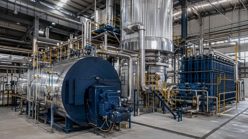
Here’s where the site-level energy picture gets interesting. A common layout on medium-sized industrial sites pairs a main steam boiler driving a back-pressure turbine for electricity generation with a separate thermal oil circuit serving process heating. These two systems often run in isolation from each other — which is a waste. The exhaust steam leaving the back-pressure turbine is typically at 0.3–0.6 MPa and 150–200°C, still carrying substantial enthalpy. That low-pressure exhaust can supply a steam-to-thermal-oil pre-heat exchanger, warming the cold thermal oil return before it reaches the fired heater. The fired heater then only needs to top the fluid up to process temperature rather than heating from cold return. Done correctly, this cascade arrangement can push overall site energy utilization above 85%, compared to the 55–65% you’d see running the two systems independently with no heat linkage.
Integrating back-pressure turbine exhaust steam with a thermal oil pre-heat exchanger can raise overall site energy utilization above 85%.True
CHP systems with heat cascading consistently achieve 75–90% overall thermal efficiency according to established thermodynamic accounting; the specific figure depends on load factors, fluid temperatures, and heat exchanger sizing, but 85%+ is achievable on well-matched sites.
The interconnection P&ID for this kind of cascade is not complicated, but it needs to be designed from the start — retrofitting heat exchangers into existing thermal oil circuits with limited physical space and no pre-designed tie-in points is genuinely painful, and the civil cost alone can kill the project economics.
Hot Water Boiler Integration with District Heating and Process Substations
Hot water boilers operating in the 95°C to 150°C range serve district heating rings, plant HVAC systems, and low-temperature process circuits like blanching lines or washing stations. Their integration challenges are mostly hydraulic rather than thermodynamic. Pressure decoupling between the boiler primary circuit and the distribution network almost always needs a plate heat exchanger at the substation — running a district heating ring directly off the boiler without decoupling creates problems when you add new substations, change pump configurations, or need to isolate a section for maintenance.
Circulating pump sizing matters more than most specifiers realize. Undersized pumps on a long ring main produce uneven temperature distribution; the substations furthest from the pump see lower supply temperatures, which shows up as heating complaints in winter and occasionally as biological growth in water treatment systems. Expansion vessel sizing and pressurization — typically nitrogen bladder vessels on closed systems — needs to account for the full system water volume and the temperature swing from cold fill to operating temperature. Anti-corrosion water treatment (deaeration, pH control, oxygen scavenging) is not optional; a hot water boiler running on untreated water in a hard-water region will lose its heat exchanger surfaces to scale within two to three seasons.
Safety Integration Specifics for Thermal Oil Systems
Thermal oil systems deserve careful attention in the plant’s safety instrumented system (SIS) design. Hot organic heat transfer fluid leaking onto a hot surface — a flanged joint near the heater itself, a pump seal failure — can auto-ignite. The expansion tank must be nitrogen-blanketed to prevent oxidation of the fluid at elevated temperatures, and the inert gas supply needs to be tied into the SIS so that a confirmed leak event closes the isolation valves and maintains blanket pressure rather than losing it. Leak detection, typically by thermal imaging on a routine schedule or by fixed point detectors near pump seals and expansion joints, should feed alarms to the DCS. Fire suppression interface with the plant SIS needs to be engineered, not bolted on afterward.
Fluid degradation is another operational reality. Thermal oil breaks down over time, especially if it’s repeatedly overheated above its rated maximum. Acid number and viscosity checks on a quarterly or semi-annual basis are standard practice; running degraded fluid increases fouling rates in heater coils and raises fire risk. It’s a maintenance discipline that gets skipped on busy plants and then causes expensive tube failures.
Taishan Thermal Oil Heater Integration Capabilities
Taishan’s thermal oil heater range covers heat outputs from roughly 350 kW up to 14 MW, with fuel options including natural gas, diesel, light fuel oil, biomass, and coal. The heaters are designed for direct integration with existing process heat exchanger networks, and the engineering team provides P&ID and tie-in design services for connecting to client-side thermal oil circuits, condensate recovery systems, and flue gas economizer packages. For sites running parallel steam and thermal oil systems, the cascade integration design — linking turbine exhaust heat into the thermal oil pre-heat circuit — is handled as part of the EPC scope rather than as an afterthought.
Mechanical and Piping Interface Engineering: Connecting a New Boiler to Existing Site Systems
The thermodynamic case for integration can be airtight, and the equipment selections can be perfect on paper — and the project still fails because someone underestimated what it takes to physically connect a new boiler to an existing system without tearing up the plant. This is where most integration budget overruns actually originate.
Pipe Stress Analysis and Steam Main Routing
A DN300 main steam pipe operating at 540°C will expand roughly 4–5 mm per meter relative to its cold installation length, depending on the pipe material (P91 Cr-Mo steel versus standard carbon steel moves differently) and the actual delta-T from ambient. On a 40-meter run, that’s 160–200 mm of thermal growth that has to go somewhere. If you tie that new steam main into an existing header without a proper stress model, you’re loading turbine nozzles and existing supports in ways nobody calculated.
CAESAR II is the industry standard for this work, though equivalent FEA-based pipe stress tools are used by some EPC contractors. The point is that the analysis must be done — not estimated — and it must include the existing pipe support structure. Before any tie-in, get a survey of the existing support locations, spring hanger settings, and snubber conditions. Supports that were sized for the original boiler’s pipe loads may be underrated once a second steam source is added. I’ve seen projects where this wasn’t caught until hydrostatic testing, and retrofitting support frames inside an operating plant is expensive and disruptive.
Isolation and Bypass Valve Sequencing
The minimum valve package at a new boiler’s steam outlet should include: a main steam stop valve (motorized gate or globe, full-bore), a turbine bypass valve routing steam to the condenser or flash vessel during startup and trip events, a non-return check valve preventing backflow from the live header into a tripping boiler, and safety relief valves sized to the boiler’s full relieving capacity. That sequence matters operationally — during a boiler startup, the bypass must be open and confirmed before the stop valve cracks, ensuring the turbine isn’t exposed to wet or pressure-transient steam. During an emergency trip, the stop valve isolates first, the non-return check provides backup, and the bypass handles any steam trapped in the superheater circuit. Get the interlock logic written into the DCS before commissioning, not during.
Expansion Joints and Turbine Nozzle Load Limits
Turbine OEMs publish allowable nozzle forces and moments — typically in their installation manuals — and these limits are tighter than most people expect. Bellows expansion joints at the boiler outlet nozzle decouple the boiler’s thermal movement from the turbine casing, which is precision-machined to tolerances that don’t tolerate unexpected loads.
Exceeding turbine OEM nozzle load limits voids the turbine warranty and can cause casing distortion leading to blade rub.True
Turbine casings are precision-machined components with tight clearances between stationary and rotating elements. Excessive piping forces or moments introduce casing distortion that closes blade-to-casing clearances, leading to rub, vibration, and potential catastrophic failure. OEMs universally include nozzle load limits in their installation specifications, and non-compliance typically voids warranty coverage.
Specify bellows joints rated for full steam conditions — pressure, temperature, and cyclic movement — not just ambient ratings. This is one place where buying to the cheapest spec comes back hard.
Feedwater System Tie-In
Connecting a new boiler’s feedwater line to an existing deaerator looks straightforward but requires a few checks that often get skipped. Deaerator storage volume should provide at least 10–20 minutes of feedwater supply at maximum continuous rating (MCR) — this buffer handles transients during load swings without starving the boiler. If the new boiler adds significant feedwater demand, verify that figure against the combined MCR, not just the original boiler’s.
Boiler feedwater pump (BFP) discharge pressure is the other common gap. An existing BFP sized for the original boiler may not have adequate head margin for the new boiler’s drum pressure plus static height plus control valve differential. Control valve sizing for the new feedwater regulating valve also needs to account for the full flow range, including minimum stable flow during low-load operation.
Flue Gas Ductwork Integration
Adding waste heat recovery equipment to an existing boiler or connecting new boiler flue gas to shared ductwork requires gas-tight construction. Seal welds at all duct flanges are standard — gasketed connections leak under the pressure cycling that happens during soot blowing and load changes. Commission bypass dampers on the new duct sections before the main boiler goes live; this lets the existing economizer or air preheater remain in service during boiler installation and cold-loop testing without forcing a plant outage.
Damper seating quality matters here. A poorly seating bypass damper in a hot duct is a maintenance headache and a heat loss that shows up directly in fuel bills.
Insulation and Heat Tracing
Steam piping above 300°C needs multi-layer mineral wool insulation with aluminum cladding — not a single thick layer, which is harder to install correctly around supports and valves and tends to leave cold spots. Properly designed insulation on a 540°C main steam line keeps surface temperatures below 50°C for personnel safety and limits heat loss to roughly 50–80 W/m² depending on pipe diameter and ambient conditions.
For overseas installations in cold climates — northern Russia, central Asia, parts of the Middle East with cold winters — condensate return lines need electric heat tracing. High-viscosity condensate, particularly from some process applications, can solidify or become unpumpable when ambient temperatures drop below 0°C. This is a seasonal effect that gets overlooked during summer commissioning and surfaces as an emergency call in January.
Control System and Instrumentation Integration: Coordinating Boiler, Turbine, and Heat Recovery Automation
Getting the pipes right is the half of integration that’s visible. The control architecture is the half that actually determines whether the system runs safely and efficiently — or whether your operators are constantly fighting pressure swings, drum level alarms, and nuisance trips.
The Control Hierarchy and Why It Has to Be Explicit
In a properly configured integrated plant, there are at least three distinct control layers, and they need to communicate with each other in a defined, tested sequence — not improvised at commissioning.
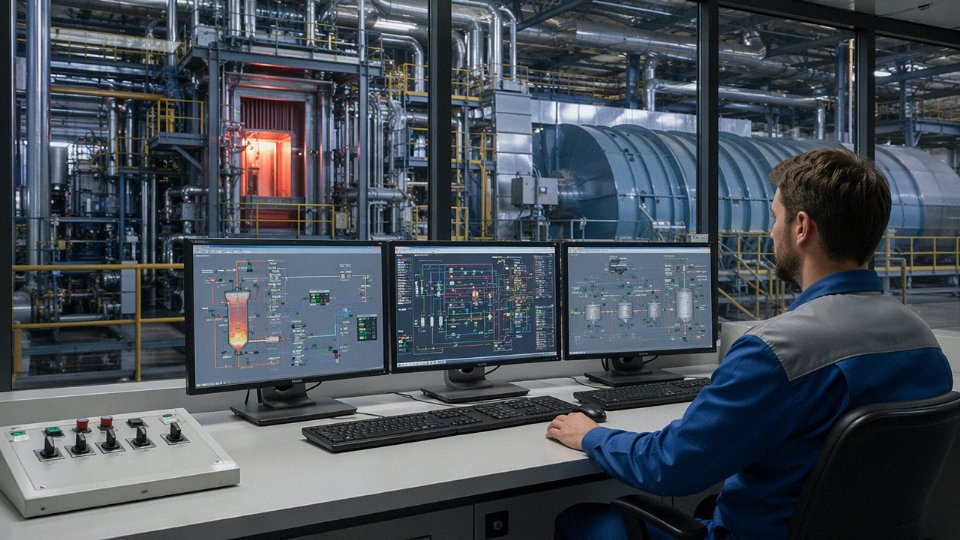
At the top sits the plant-level DCS, which handles load dispatch: it decides how much steam generation is demanded from the boiler at any given moment based on turbine load, process header pressure, and sometimes a power export target. Below that is the boiler management system (BMS/BCS), which owns combustion control, drum level, and steam temperature. Separate from both — and often supplied by the turbine OEM with its own proprietary software — is the turbine governor, which manages speed, load ramp rate, and trip logic.
The critical point: hardwired interlock signals must cross all three boundaries. Turbine trip → immediate boiler master setpoint runback. High drum pressure → turbine load limit signal. BMS burner-out → turbine protection alarm. These cannot rely solely on network communication; they must be hardwired 4–20 mA or dry-contact signals with defined fail-safe states. Any integration project that routes all interlock logic through an Ethernet link is asking for trouble during a network fault.
Key Integration Signals in Practice
Boiler master pressure setpoint should track the turbine inlet pressure measurement — not just a fixed setpoint — so that the boiler responds to real conditions at the turbine flange rather than some assumed steady state. This matters most during load changes, when turbine throttle position shifts and steam demand changes faster than a fixed setpoint loop can follow.
Drum level three-element control is standard on any serious industrial boiler, but in an integrated plant the feedwater flow signal has a complication: if your BFP is VFD-driven (which it should be, for energy efficiency), and the turbine has an extraction port supplying feedwater heating, then a change in turbine extraction flow directly affects feedwater enthalpy and, subtly, the effective feed flow rate at the drum. Your three-element loop needs to account for this, or you’ll see drum level wander during turbine load transitions. In practice, this means adding a feedwater enthalpy correction or at minimum tuning the three-element controller with the turbine at multiple load points, not just at full load.
Boiler-Following vs. Turbine-Following: Pick One, Program the Switchover
Turbine-following mode — where the boiler holds steam pressure and the turbine governor adjusts load to match — suits process-steam-priority plants. If your site needs stable header pressure for process equipment, this is usually the right default.
Boiler-following mode — where the turbine governor holds frequency or power output and the boiler tracks the resulting steam demand — suits power-export sites or grid-connected generation. The boiler essentially chases whatever the turbine needs, which demands faster combustion response and more aggressive feedforward action in the BCS.
The switchover between modes has to be programmed with bumpless transfer logic. A hard switch between modes without proper initialization of the receiving controller’s output will produce a pressure transient — potentially large enough to lift safety valves or trip the turbine on overpressure. This is not a theoretical risk; it happens on real plants during routine mode transitions if the logic wasn’t tested carefully. The bumpless transfer should be tested in simulation, with artificial load steps, before the turbine ever sees live steam from the new boiler.
HRSG Integration: Where Control Gets More Complicated
When there’s a gas turbine with an HRSG in the loop, the control complexity goes up significantly. The bypass stack damper — which diverts GT exhaust away from the HRSG during GT startup or shutdown — needs interlocked control with both the GT load signal and the HRSG drum level status. Opening the damper while the drum still has pressure and temperature can cause rapid thermal cycling of the HRSG tubes if not managed carefully.
Duct burner fuel control must interlock with GT load: if the GT trips, fuel to the duct burner needs to cut immediately, because without GT exhaust flow the duct burner is firing into a stagnant or reversing gas path — a combustion hazard. This interlock is sometimes missed on supplementary-firing retrofits where the duct burner control was added by a different contractor than the original HRSG supplier.
Steam bypass valves (turbine bypass to condenser) during GT startup are a frequent source of commissioning headaches. The bypass valve needs to modulate — not just open/close — to control steam temperature and pressure ramp rate during the startup transient. A simple on/off bypass valve on a high-pressure HRSG is inadequate.
Communication Protocols and Cybersecurity
Most boiler PLCs in modern integrated plants communicate via OPC-UA, Modbus TCP, or PROFIBUS DP, depending on the vintage of the plant DCS. OPC-UA is increasingly the right choice for new installations because of its built-in security model, but plenty of operating plants still run Modbus TCP or even legacy PROFIBUS, and integration means meeting the existing plant where it is.
IEC 62443 cybersecurity standards apply to industrial control systems including boiler and turbine automation networks at overseas industrial plantsTrue
IEC 62443 is the internationally recognized series of standards for industrial automation and control system (IACS) cybersecurity, covering network segmentation, access control, and security levels applicable to plant DCS, BMS, and turbine control systems globally.
For overseas plants — particularly in regions where remote access for OEM support is common — network segmentation between the boiler/turbine control network and the plant IT network is not optional. A flat network where the boiler PLC is reachable from the corporate LAN is a serious vulnerability. Minimum expectation is a demilitarized zone (DMZ) architecture with a data diode or firewall between the control network and any external-facing system. Access control logs for all remote sessions should be retained.
What Taishan’s Engineering Team Provides
Our control integration scope is not limited to specifying the boiler BMS and handing over an I/O list. For integrated projects, the team develops the full cross-system I/O list — boiler signals, turbine interlock interfaces, HRSG damper controls — and conducts factory acceptance testing (FAT) using simulated turbine trip signals and load ramp sequences before the equipment ships. On-site commissioning includes live interlock testing with the actual turbine system, step-by-step verification of bumpless transfer logic, and tuning of the boiler master and three-element drum level loops under real operating conditions. That last step — loop tuning under real load — is where a lot of integration projects either come together or fall apart, and it’s not something that can be delegated to whoever is on site that week.
Emissions Compliance and Environmental System Integration for Integrated Power-Heat Plants
Running a boiler-turbine CHP plant without a coherent emissions strategy is a fast way to lose your operating permit — and in export markets, it can kill a project before commissioning is even complete. Emissions compliance for integrated plants is genuinely harder than for a standalone boiler because you’re coordinating flue gas treatment equipment across multiple heat sources, shared stacks, combined gas volumes, and a DCS that has to log everything continuously. The engineering is solvable, but it has to be designed in from the start, not bolted on later.
Global Emissions Benchmarks That Shape Equipment Specification
The EU Industrial Emissions Directive remains the reference standard most international lenders and EPC clients reach for first, even on projects outside Europe. For solid-fuel boilers above 50 MWth, IED limits sit at NOx below 200 mg/Nm³, SO₂ below 200 mg/Nm³, and particulate matter below 20 mg/Nm³ — all at 6% O₂, dry basis. These are not conservative limits; meeting them on a CFB firing mixed biomass and coal gangue requires a complete flue gas treatment train. The World Bank IFC Performance Standards are broadly similar and are routinely required by development finance institutions funding industrial projects in Southeast Asia, South Asia, and Sub-Saharan Africa. In practice, many industrial zones in Vietnam, Bangladesh, and Nigeria are now setting local limits that reference IFC standards, so designing to IED/IFC from the outset avoids expensive retrofits when regulations tighten — which they always do.
SCR Placement and Its Knock-On Effects on Draft System Capacity
Selective catalytic reduction is the primary NOx control route for coal and biomass-fired boilers in integrated plants. The two placement options — high-dust SCR between the economizer outlet and the air preheater, or low-dust SCR after the electrostatic precipitator — each carry real operational trade-offs. High-dust SCR operates at the catalyst’s preferred temperature window, roughly 300–400°C, which means better NOx conversion efficiency and a smaller reactor for the same duty. The downside is catalyst fouling from fly ash, especially on fuels with high calcium or alkali content. Low-dust SCR protects the catalyst but requires a flue gas reheater to restore temperature after the ESP, adding capital cost and a persistent auxiliary energy load.
The pressure drop across an SCR reactor is typically 500–1,000 Pa depending on catalyst layer count and face velocity. That sounds small until you’re adding SCR to an existing boiler whose induced draft fan was sized without any margin. In my experience, this is one of the most common sources of expensive surprises on retrofit projects. Always audit the ID fan curve against the new system resistance before committing to SCR placement — upgrading an ID fan impeller or motor mid-project costs both time and money.
Adding a high-dust SCR to an existing boiler without re-evaluating ID fan capacity will cause insufficient draft margin at full load.True
SCR reactors introduce 500–1,000 Pa additional pressure drop into the flue gas path. If the original ID fan was specified with minimal margin, this addition will push operation beyond the fan's stable operating range at MCR, resulting in draft instability or combustion problems.
When a new boiler is added to a site that already has an operating unit, the instinct is to route both flue gas streams to a single wet flue gas desulfurization absorber to save capital. That’s reasonable, but the absorber, slurry recirculation pumps, and oxidation air blowers must be sized for the combined MCR flue gas volume of both units simultaneously — not the average load, not a diversity factor. Plants that undersize shared WFGD absorbers end up with SO₂ exceedances during startup of the second unit, which triggers regulatory reporting events at exactly the moment the plant is trying to demonstrate compliance.
Slurry preparation, limestone grinding, and gypsum dewatering circuits all scale with gas volume and inlet SO₂ concentration. A site switching from low-sulfur biomass to higher-sulfur coal blends — a common fuel strategy when biomass prices rise seasonally — can push SO₂ inlet loads well above the original design point. Build in some absorber headroom, at least 10–15% above calculated MCR, and specify variable-speed drives on recirculation pumps to manage partial-load operation without excessive limestone consumption.
CEMS Integration with Plant Environmental Reporting
Continuous emissions monitoring systems must measure NOx, SO₂, CO, O₂, particulate matter, and flue gas flow rate at each stack. In an integrated plant with a shared stack serving multiple heat sources, the CEMS placement and the regulatory basis for reporting — whether the measurement represents each boiler independently or the combined emission — needs to be resolved with the permitting authority before construction starts, not after. Signal routing to the plant DCS should be hardwired with a dedicated data historian, not reliant on the turbine control network, which may have maintenance windows or firmware updates that interrupt logging. Calibration gas cylinder changeouts and zero-span checks should be scheduled during low-load periods to avoid interrupting normal boiler-turbine operation.
Ash and Solid Waste Routing
CFB and stoker boilers in CHP configurations generate three separate solid streams: fly ash collected by the ESP or bag filter, bed ash or bottom ash from the furnace, and FGD gypsum or calcium sulfite sludge. Each stream has different handling requirements and, potentially, different regulatory classifications depending on fuel type and local waste codes. The critical operational concern is keeping these streams physically separated from the turbine condensate system and cooling water circuits. A bag filter ash conveying pipeline routed too close to a condenser tube bundle, or gypsum slurry drainage finding its way into a cooling tower basin, creates water quality problems that are time-consuming and expensive to remediate. In a well-designed plant layout, ash handling conveyors and slurry trenches are positioned on the opposite side of the boiler house from the turbine hall, with bunded containment and separate sumps.
Noise and Vibration Compliance in Integrated Plant Layouts
Large FD and ID fans on boilers above 50 MWth routinely generate sound pressure levels of 95–110 dB(A) at one meter without attenuation — well above typical industrial site boundary limits of 65–75 dB(A) during daytime hours. Octave-band noise assessments should be completed at the conceptual layout stage, not after civil foundations are poured. Inlet silencers on FD fans, discharge silencers on ID fan outlets, and acoustic enclosures around feedwater pump sets are standard mitigation measures. Steam safety valve exhaust silencers are often overlooked; a 150 mm safety valve lifting on a 9.8 MPa boiler produces an impulse noise event that can exceed 130 dB(A) at close range and will generate complaints and potentially regulatory action if it happens frequently. Specify pilot-operated safety valves where possible — they open and close more cleanly than spring-loaded valves and reduce the frequency of noisy partial lifts during pressure fluctuations.
EPC Project Execution: Engineering, Procurement, and Construction Workflow for Boiler-Turbine Integration Projects
Integration projects fail more often in the execution phase than in the engineering phase. A technically sound design can unravel fast if procurement lead times aren’t sequenced correctly, if the civil survey missed a buried service, or if nobody pinned down the turbine OEM’s governor interface requirements before the DCS I/O list was frozen. What follows is how a competent EPC contractor structures this work — and where the critical handoffs are.
Phase 1 — Site Survey and Feasibility Study (Weeks 1–8)
This phase is underestimated constantly. The actual deliverable isn’t a glossy report; it’s a set of verified boundary conditions that every downstream engineering decision depends on.
Turbine data collection starts with the OEM nameplate and goes much further. You need the actual steam inlet conditions the turbine was commissioned at — not just the rated design values — along with allowable nozzle loads (typically specified in the OEM’s installation manual as force and moment limits at the main steam flange), and the governor interface signal type. An older turbine might use a 4–20 mA speed reference signal; a newer unit might expect a PROFIBUS or Modbus handshake. Finding this out in week 40 is expensive.
If there’s an existing HRSG on site, the audit covers current exhaust gas temperature (typically 450–600°C from a gas turbine, lower from reciprocating engines), any supplementary duct burner capacity already installed, and the condition of the steam drum and HP/LP steam headers. A unit that has been running 12 years on natural gas and is about to receive steam from a new CFB burning coal gangue and biomass blend is going to see different steam chemistry, and you need to know whether the existing HRSG internals and water treatment system can handle that.
Fuel analysis at this stage isn’t optional — it’s the basis for combustion calculations, furnace sizing, and emissions permit applications. For biomass and MSW fuels especially, chlorine content, moisture, and ash fusion temperature all vary seasonally and by supplier. Lock in the fuel specification range, not just a single sample.
The civil and structural survey should include boiler foundation soil bearing capacity, available headroom in the turbine hall for steam pipe tie-in, and the routing path for the main steam line — including any existing underground cable trenches or drainage structures that would force a pipe detour.
Phase 2 — Basic Engineering and Integration Design (Weeks 9–20)
Heat and mass balance is the first real engineering output. From this, boiler rated capacity is confirmed (or adjusted), extraction steam flows to process are defined, and the HRSG supplementation strategy — whether duct firing, parallel header connection, or unfired supplementation — is locked. The P&ID covering the boiler-turbine-HRSG interface should be finalized by roughly week 16–18 at the latest; delay here cascades into every subsequent phase.
Preliminary piping stress analysis matters now, not at detailed design. Main steam lines operating at 9.8 MPa and 540°C expand significantly — a 40-meter run of 273 mm OD pipe can grow 60–80 mm thermally, depending on layout and material — and the expansion loop or bellows design affects both the turbine nozzle load check and the civil structure layout.
Regulatory permit strategy needs to run in parallel, not sequentially. Permit timelines in Southeast Asia, the Middle East, and sub-Saharan Africa vary from three months to well over a year depending on boiler pressure rating, fuel type, and local environmental authority workload. Starting this process at week 12 rather than week 24 is the difference between commissioning on schedule and sitting on a mechanically complete plant waiting for a stamp.
Phase 3 — Detailed Engineering and Procurement (Weeks 21–52)
Pressure parts fabrication drawings are released early in this phase — superheater tube bundles, steam drum, and economizer sections all have lead times of 14–22 weeks depending on the pressure rating and whether third-party inspection is required. Long-lead procurement runs concurrently: main steam stop valves (Class 1500 or higher for supercritical applications), turbine bypass valves, and the DCS hardware itself. The DCS I/O list should be issued to the controls vendor no later than week 26 if you want cabinets delivered before construction crews finish the control room.
Civil and structural design for the boiler house and stack foundation proceeds in parallel. Steel structure fabrication for a 75 MW boiler house can take 10–14 weeks, and it needs to be on site before pressure part erection begins.
Phase 4 — Construction and Installation (Weeks 30–72, Overlapping with Procurement)
The overlap with procurement is intentional and necessary. Boiler steel structure erection typically begins around week 32–36 depending on civil readiness; pressure part erection follows as modules arrive from the fabrication shop. Refractory installation — a step that gets rushed on too many projects — requires proper curing time. Skipping or compressing the dry-out schedule to chase a commissioning date is a common cause of refractory spalling during initial firing.
Steam pipe fabrication and installation follow ASME B31.1 or EN 13480 (depending on the export destination), with hydrostatic test at 1.5× design pressure before any insulation is applied. Insulation and cladding are the last step — not a place to recover schedule time by starting before the hydrostatic test is signed off.
Phase 5 — Commissioning and Performance Testing (Weeks 70–80)
Steam blowing is the step most clients don’t fully appreciate until they’ve seen what comes out of a new main steam line during the blow. Mill scale, weld slag, and construction debris will destroy turbine blades if they reach the first stage nozzles. The blowing procedure — typically using a temporary target plate method — continues until the target plate shows no new impact marks over two consecutive blows. This can take 4–10 blow cycles over several days, depending on pipe length and system cleanliness.
Boiler-turbine interlock testing covers every protection scenario: turbine trip on boiler low drum level, boiler load runback on turbine governor fault, bypass valve opening on load rejection. Every interlock is tested in simulation first, then with real process conditions.
The 72-hour continuous reliability run is the contractual milestone most owners focus on. Performance testing to ASME PTC 4 (or equivalent national standard where required) establishes guaranteed efficiency and output values for the contract record.
Taishan Group holds ASME S and U stamp certification for boiler fabrication, enabling direct export of pressure vessels to ASME-code jurisdictions without third-party re-certification.True
ASME S and U stamps are issued by the American Society of Mechanical Engineers after documented quality system audit and are required for boiler and pressure vessel acceptance in many international markets including the United States, Canada, and numerous countries that adopt ASME as their reference standard.
Taishan Group has delivered integrated boiler-turbine EPC projects across Southeast Asia, South Asia, the Middle East, and Africa — working with resident site engineers through each construction and commissioning phase rather than handing over drawings and stepping back. CE marking is available for European-export equipment. The single-source EPC structure matters here: when the boiler supplier, the integration engineer, and the commissioning team are the same organization, the coordination gaps that sink multi-vendor projects simply don’t exist.
Frequently Asked Questions About Power Plant Boiler Integration with Turbines and Heat Recovery Systems
Can an existing back-pressure turbine accept steam from a new CFB boiler if the pressure rating is different?
Yes, but not without a pressure-reducing and desuperheating (PRDS) station between the two. A CFB boiler rated at 9.8 MPa / 540°C feeding a turbine designed for 3.8 MPa inlet conditions requires controlled letdown — temperature trimming with spray water is equally critical, not just pressure reduction. The thermodynamic penalty is real but usually acceptable when the site’s primary goal is process steam supply rather than squeezing maximum shaft power from every kilogram of steam. In practice, a detailed heat balance study — done before any purchase order goes out — will quantify the enthalpy loss across the PRDS and tell you exactly how many kilowatts you’re leaving on the table. Don’t skip that step.
What is the minimum steam flow a boiler must supply to keep a turbine online without tripping on low-flow protection?
Most industrial steam turbines have a minimum stable load somewhere in the 20–30% of rated inlet flow range, though the exact threshold depends on turbine design, rotor diameter, and the manufacturer’s bearing lubrication specification. Drop below it and two things happen quickly: blade cooling becomes inadequate, and bearing oil temperatures start drifting outside the normal band — both are trip precursors. The boiler’s turndown capability at that lower bound is therefore a hard selection criterion, not a footnote. A boiler that can only sustain rated output or nothing is useless in partial-load operation. CFB units generally handle turndown well (down to roughly 25–30% MCR); fire-tube and some smaller water-tube units may need auxiliary firing or bypass arrangements to stay above the turbine’s minimum flow floor.
Can a thermal oil boiler be used to generate steam for a turbine?
Not directly. Thermal oil systems produce a circulating high-temperature liquid — typically synthetic or mineral heat transfer fluid at 250–320°C at near-atmospheric pressure — and that fluid cannot be admitted to a steam turbine. A thermal oil-to-steam vaporizer (shell-and-tube or plate-type) can generate steam, but the achievable pressure is limited by the oil-side temperature; in most installations this works out to roughly 0.6–1.0 MPa saturated steam, which is well below any meaningful power-generation turbine inlet requirement. Useful for deaeration, feedwater preheating, or process heat. Not useful for shaft power.
How long does it take to integrate a new 75 t/h power plant boiler into an existing turbine-based cogeneration system?
Budget 14–20 months from contract signing to first steam admission to the turbine for a medium-complexity project. The critical path is almost always boiler pressure part fabrication — drum, headers, membrane walls — which typically runs 20–28 weeks depending on steel plate availability and shop load. Main steam piping stress analysis and spool fabrication adds another 12–16 weeks and can overlap partially with boiler manufacture, but only if the P&ID is locked early. Delays in civil foundation approval or grid connection permitting can easily add 2–4 months on top of that. Experienced EPC teams front-load the regulatory and interface engineering work in the first six months precisely to avoid those compounding delays later.
What boiler efficiency can we expect after integrating waste heat recovery economizers and air preheaters?
A well-configured boiler recovering heat from flue gas at roughly 350°C down to around 130°C — which is close to the acid dew point limit for sulfur-bearing fuels and where you generally stop to avoid cold-end corrosion — typically achieves 88–92% thermal efficiency on a lower heating value basis. Without tail-end heat recovery, the same boiler usually lands at 78–82%. That 3–8 percentage point gain translates directly to fuel savings, and at any meaningful scale those savings justify the capital cost of the economizer and air preheater within a few years. The exact number depends on flue gas volume, fuel sulfur content, feedwater inlet temperature, and ambient air temperature in winter versus summer — seasonal variation is real and worth including in the annual average calculation.
Adding both an economizer and an air preheater to a coal-fired water-tube boiler can improve thermal efficiency by 3–8 percentage points compared to operation without tail-end heat recovery.True
This range is consistent with heat transfer engineering fundamentals and widely reported in boiler OEM test data; the actual gain depends on flue gas temperature, fuel type, and feedwater inlet conditions.
Does adding a new boiler to an existing HRSG steam header require re-certification of the pressure system?
Yes, in essentially every jurisdiction that follows recognized pressure equipment codes. Connecting a new pressure source to an existing classified pressure header is a modification — full stop — and that triggers re-inspection under whatever directive applies: PED 2014/68/EU in Europe, ASME B31.1 and relevant state/local boiler laws in North America, or the equivalent national code elsewhere. Taishan’s EPC team treats this regulatory process as an integrated part of project scope, not an afterthought, because discovering the re-certification requirement after piping is already fabricated is an expensive way to learn.
What fuel flexibility options are available for a power plant boiler intended for turbine integration on a site where fuel supply may shift over the project lifetime?
CFB technology is the most defensible choice when fuel supply is genuinely uncertain. Coal, biomass, coal gangue, municipal solid waste, petroleum coke, sewage sludge — CFB units can handle blends and fuel switches that would cause serious problems in a pulverized-coal or stoker-fired unit, while still maintaining the stable 9.8 MPa / 540°C steam parameters that turbine integration demands. For sites where the fuel is reliably gaseous or liquid but the specific grade may change, a dual-fuel or tri-fuel burner system on a water-tube boiler — gas/diesel/heavy fuel oil — allows switching without shutdown. The honest caveat: no single boiler design optimizes equally for all fuels, so the selection should be driven by the realistic probability-weighted fuel scenario over the boiler’s 25–30 year service life, not just the cheapest option available at contract signing.
Selection Checklist and Next Steps: Specifying a Power Plant Boiler for Your Integration Project
Getting a boiler-turbine integration project right starts well before anyone draws a P&ID. The proposals that go sideways — the ones that come back with equipment that won’t fit the site, or steam parameters that don’t match the turbine inlet, or a DCS that can’t talk to the new boiler controller — almost always trace back to incomplete information at the enquiry stage. Here is what you actually need to pull together before you contact any boiler manufacturer.
The 12 Data Points You Need Before Requesting a Proposal
Work through this in order. Some items are obvious; a few trip up even experienced procurement teams.
| # | Data Point | Why It Matters |
|---|---|---|
| 1 | Turbine OEM, model, rated inlet pressure and temperature, and steam flow range | Determines boiler rated pressure, superheat temperature, and MCR output — the non-negotiable starting point |
| 2 | Existing HRSG or waste heat boiler capacity and current steam parameters | Identifies whether the new boiler runs in parallel, in supplementary mode, or as sole steam source |
| 3 | Site fuel: type, net calorific value, moisture, ash content, and supply reliability | Drives furnace type (CFB, grate, pulverised, oil/gas), sizing margins, and fuel handling scope |
| 4 | Required steam output at MCR and minimum stable load | Sets the turndown ratio requirement — underspecify this and you get instability at partial load |
| 5 | Available site footprint, height limit, and access routes for heavy lifts | A drum boiler at 100 t/h and 9.8 MPa needs real vertical clearance; an undersized plot forces a more expensive modular or bi-drum arrangement |
| 6 | Grid connection capacity and power export tariff or wheeling arrangement | Affects whether a back-pressure or condensing turbine configuration makes commercial sense |
| 7 | Applicable emissions standards, permit conditions, and any future tightening already announced | NOx, SO₂, particulate, and mercury limits determine the FGD/SCR/bag-filter scope that must be costed into the integration package from day one |
| 8 | Cooling water source, temperature range, and seasonal availability | Condensing turbine applications live or die on cooling capacity — a river intake that drops to a trickle in dry season will derate your output significantly |
| 9 | Existing deaerator rated capacity and boiler feed pump duty | A new boiler adding 40–60 t/h of feedwater to an already-loaded BFP circuit is a real problem if it was not scoped early |
| 10 | Plant DCS brand, version, and fieldbus/communication protocol | Avoids the three-month delay that happens when a SIMATIC S7-based turbine controller cannot handshake with an unfamiliar boiler management system without a protocol converter that nobody budgeted |
| 11 | Project schedule constraints: commercial operation date, any outage windows for tie-in | Drives whether shop-fabricated modular sections are necessary versus field-erected, which affects cost by 15–30% depending on local labour rates |
| 12 | EPC versus supply-only procurement preference | A supply-only contract hands coordination risk back to the buyer; full EPC removes it — important to decide before pricing because scope boundaries change significantly |
What a Taishan Proposal Actually Covers
Once we receive complete site data, our overseas project team delivers a preliminary proposal within roughly 2–3 weeks. That package includes a heat and mass balance (covering boiler, turbine extraction points, and heat recovery circuits), a boiler general arrangement drawing to scale, an integration P&ID schematic showing all steam, feedwater, blowdown, and flue gas interfaces, preliminary civil foundation loading data for your structural engineer, an indicative project schedule broken into engineering, procurement, fabrication, and commissioning phases, and a commercial offer with clear scope boundaries.
This is not a brochure. It is enough for your engineering team to run a proper technical review and for your finance team to model the project economics.
Integration Risks Worth Watching
Steam parameter mismatch between a new boiler and an existing turbine is the most common technical issue — usually handled by a pressure-reducing and desuperheating station (PRDS) or, where the gap is small, by agreeing a boiler re-rating with the turbine OEM. Pipe stress incompatibility appears later and costs more to fix; early finite-element stress analysis of the interconnecting piping, especially at high-pressure superheated steam conditions above 4 MPa, prevents expensive field modifications during construction. Control system communication gaps between the boiler management system and the plant DCS are almost always solvable with protocol converters and thorough factory acceptance testing, but only if the issue is identified in the FEED phase, not during commissioning. Emissions compliance gaps — discovering that the flue gas treatment scope is insufficient for the local permit — can delay startup by months and are best resolved by treating the FGD, SCR, and continuous emissions monitoring system as an integral part of the boiler integration scope rather than a separate contract.
Taishan Group manufactures the full range of industrial and power plant boilers — coal-fired, CFB, biomass, gas/oil, waste heat, thermal oil, and MSW incineration — together with in-house auxiliary equipment design and EPC delivery capability.True
This is consistent with Taishan Group's documented product range and EPC service offering for industrial and power plant projects.
Why Single-Source EPC Matters Here
The most common cause of integration project delays is not equipment quality. It is the coordination gap between multiple suppliers who each delivered their scope correctly but whose interfaces were never properly resolved between them. When the boiler vendor, the turbine vendor, the civil contractor, the DCS integrator, and the stack monitoring supplier are all working from different revisions of the P&ID, someone pays — usually the plant owner, in commissioning delays and startup rework.
Taishan Group’s position as a manufacturer of the full boiler range, with in-house auxiliary equipment engineering and an EPC team that has executed overseas industrial projects across a range of regulatory environments, eliminates that gap. One contract. One point of technical accountability from FEED through to performance testing.
Bring us your completed checklist. Our overseas project engineers will return a no-obligation integration feasibility assessment and indicative proposal within 15 business days.