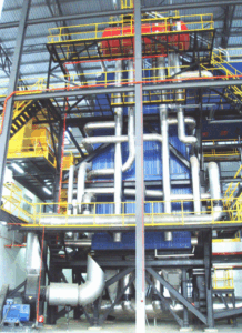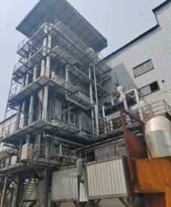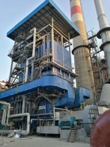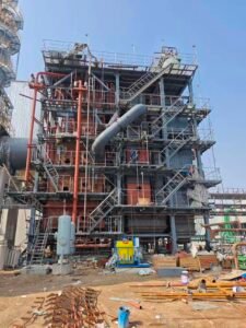
Regulatory non-compliance on a waste heat recovery boiler isn’t a paperwork problem — it’s a shutdown problem. Miss a NOx or SO2 threshold under the EU Industrial Emissions Directive or EPA MACT rules, and you’re looking at permit revocation, forced outages, and retrofit costs that can dwarf the original equipment budget. Worse, boiler selections made without accounting for the applicable emission framework often end up needing add-on SCR or FGD systems that weren’t costed into the project, blowing capital budgets and delaying commissioning by months.
Environmental and emission regulations affect waste heat recovery boiler selection primarily through NOx limits (100–200 mg/Nm³ under EU IED; sub-50 ppm under EPA MACT for certain installations), SO2 thresholds (50–200 mg/Nm³ depending on region and fuel), particulate standards, and efficiency floors that determine whether an economizer or air preheater is legally required rather than merely recommended. The applicable framework — whether GB 13271, EU IED, or a local permit — must be confirmed before specifying boiler geometry, duct sizing, and flue gas treatment auxiliaries.
What makes this genuinely complicated is that the regulations don’t converge. A cement plant in Southeast Asia exporting to Europe, running a waste heat boiler on kiln exhaust, may simultaneously face host-country emission permits, IFC Performance Standards tied to project financing, and offtake-contract clauses that reference EU BREF benchmarks — all with different reference conditions, averaging periods, and enforcement teeth. Understanding which rule actually governs your equipment selection, and where the conflicts sit, is where the engineering work really starts.
NOx Emission Limits and Their Direct Impact on WHRB Combustion and Duct Architecture
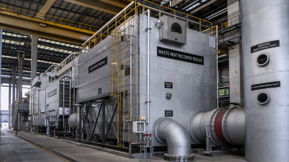
NOx is the emission parameter that most directly reshapes the physical layout of a waste heat recovery boiler. SO₂ and particulate limits matter, but they tend to drive add-on scrubbing or filter decisions that sit largely outside the WHRB pressure parts. NOx compliance, by contrast, reaches into the duct geometry, the burner specification, the flue gas recirculation piping, and — in strict jurisdictions — adds a catalyst bed that meaningfully extends the boiler’s footprint and changes the whole pressure drop budget.
Jurisdictional Thresholds You Actually Have to Design Against
The EU Industrial Emissions Directive Annex V sets 100–150 mg/Nm³ (referenced to 3% O₂, dry) for gas-fired combustion installations above 50 MW thermal. For smaller units or those burning waste-derived gases — common in cement or glass float lines feeding a WHRB — the applicable limit can shift, so always check the installation’s permit rather than the headline IED number. US EPA 40 CFR Part 60 Subpart Db covers steam generating units above roughly 29 MW heat input; Subpart Dc covers smaller units, with NOx limits varying by fuel type and typically running 0.10–0.20 lb/MMBtu for natural gas, which translates to roughly 130–260 mg/Nm³ depending on conversion assumptions. MACT standards under Part 63 for certain process heaters push harder, sometimes below 50 ppm.
China’s GB 13271-2014 sets 200 mg/Nm³ as the general limit for industrial boilers, but the ultra-low emission policy — now effectively mandatory in key regions — demands ≤50 mg/Nm³. That target is not achievable with combustion controls alone in most applications. GCC countries reference Ministerial Decision No. 209, which typically applies 200 mg/Nm³ for gas-fired plant, though individual national supplements can tighten this, and enforcement is increasingly real on large industrial projects.
Thermal NOx vs. Fuel NOx in the WHRB Context
A cement kiln exhaust arrives at the WHRB inlet at 300–950°C (depending on the process stage and whether a preheater tower is upstream). A glass furnace can deliver flue gas at 1,000°C or higher, carrying excess oxygen and — critically — already-elevated NOx from the melting process itself. That incoming NOx is fuel-NOx and thermal-NOx generated upstream; the WHRB designer cannot scrub it back out through combustion tuning. What you can control is what the supplementary duct burner adds.
Thermal NOx formation accelerates sharply above roughly 1,400°C in the flame zone. Duct burners firing into a high-temperature waste gas stream can hit that threshold easily if sizing is lazy or turndown behavior isn’t mapped carefully. Staged combustion — splitting primary and secondary air to keep peak flame temperatures down — is the first line of defense and adds relatively little capital cost if designed in from the start. Retrofitting staged air ports later is a painful, expensive job.
Flue Gas Recirculation and What It Actually Costs You
FGR ratios of 10–25% are standard practice for NOx suppression on duct burners in WHRB applications. The recirculated flue gas dilutes the combustion zone, lowers O₂ partial pressure, and reduces peak flame temperature. In practice, the lower end of that range (10–15%) is usually enough for EU IED compliance on natural gas firing; hitting ≤50 mg/Nm³ under China’s ultra-low policy typically requires the upper range combined with burner geometry optimization.
The FGR duct, fan, and control loop are not trivial additions. Budget roughly 1.5–3% of the WHRB installed cost for a properly instrumented FGR system, depending on plant scale. More importantly, the recirculation fan sees corrosive, particulate-laden gas — specifying the wrong seal or impeller material here creates a maintenance headache within two or three years of operation.
SCR vs. SNCR: Choosing the Right Post-Combustion Path
SNCR (selective non-catalytic reduction) works by injecting urea or ammonia into the flue gas at 850–1,100°C. Within a WHRB gas path, that temperature window usually corresponds to the inlet duct section or the first radiant pass, before the gas has cooled significantly. The appeal is obvious — no catalyst bed, lower capital. The problem is that SNCR NOx reduction efficiency is typically 30–60%, which is often insufficient for strict jurisdictions, and ammonia slip is harder to control precisely without the residence time and temperature uniformity that a dedicated SNCR reactor provides. In a real WHRB where the flue gas velocity and temperature profile vary with process load, that temperature window can shift substantially across the operating range.
SCR downstream of the economizer section — where gas temperatures typically run 180–400°C depending on configuration — gives far more consistent performance: 80–95% NOx reduction is achievable, with ammonia slip targets of below 2 ppm manageable through proper ammonia injection grid (AIG) design and flow distribution analysis. The tradeoff is physical space and pressure drop. An SCR catalyst bed sized for a medium industrial WHRB adds roughly 2–4 m to the overall boiler length and requires careful structural allowance if you’re working in a constrained equipment bay. Auxiliary power demand for the ammonia vaporization, AIG blower, and associated instrumentation runs 2–5% of unit auxiliary load — not enormous, but it belongs in the EPC power balance from day one, not discovered during commissioning.
SCR addition to a waste heat recovery boiler typically increases overall unit length by 2–4 m and auxiliary power consumption by 2–5%, depending on catalyst volume and AIG configuration.True
These figures reflect standard SCR module sizing for industrial WHRB applications; catalyst volume depends on inlet NOx concentration, target outlet concentration, flue gas flow rate, and operating temperature window. Values are consistent with vendor engineering data and published BREF guidance.
One practical note: catalyst poisoning is a real risk when the upstream process delivers flue gas containing alkali compounds, arsenic, or high dust loads — common in cement or metallurgical applications. In those cases, a dust-first layout (cyclone or bag filter upstream of the SCR) protects catalyst life and keeps replacement cycles closer to 4–6 years rather than 1–2 years. This sequencing decision affects the entire duct architecture and should be locked in at the process flow diagram stage, not during detailed design.
SO2, HCl, and Acid Gas Regulations Shaping WHRB Material Selection and Tail-End Treatment
Acid gas compliance is where WHRB projects get expensive fast — and where underspecified equipment fails quietly until a tube bundle is so corroded you’re looking at a forced outage measured in weeks, not days. The regulatory floor has shifted considerably over the last decade, and the binding limits now in force across the EU, China, and the US are tight enough that they dictate metallurgical decisions from the superheater all the way down to the economizer tail section.
Binding SO2 Limits and the Duty Contexts That Drive Them
Under the EU’s Large Combustion Plant Best Available Techniques Reference Document (LCP BREF), SO2 emission associated emission levels (AELs) run 50–200 mg/Nm³ depending on fuel type, plant capacity, and whether the installation falls under new-plant or existing-plant provisions. For WHRBs serving sulfuric acid plants — where the inlet flue gas can carry SO2 concentrations of several thousand mg/Nm³ before the contact process — the boiler is essentially a process step inside an acid plant, and the tail-gas treatment train determines what actually exits the stack. China’s GB 13271-2014 holds industrial boilers in general areas to 200 mg/Nm³, but key-region “ultra-low emission” zones (covering most of the eastern industrial corridor) tighten that to 50 mg/Nm³. In practice, plants in Shandong, Jiangsu, or Guangdong are essentially working to the ultra-low standard whether or not the regulation technically mandates it yet, because local environmental bureaus interpret “key region” broadly. Under US EPA 40 CFR Part 60 NSPS Subpart Da, new electric utility steam generating units face SO2 limits that push comparable design constraints on any recovery boiler integrated into a power generation train.
For smelters and cement kilns, the inlet SO2 load to the WHRB varies enormously — anywhere from a few hundred to well over 2,000 mg/Nm³ depending on ore sulfur content or clinker process stage — so you cannot assume a single flue gas composition when selecting tube materials or specifying the downstream scrubber duty.
Cold-End Corrosion: Where Most of the Metallurgical Money Gets Spent
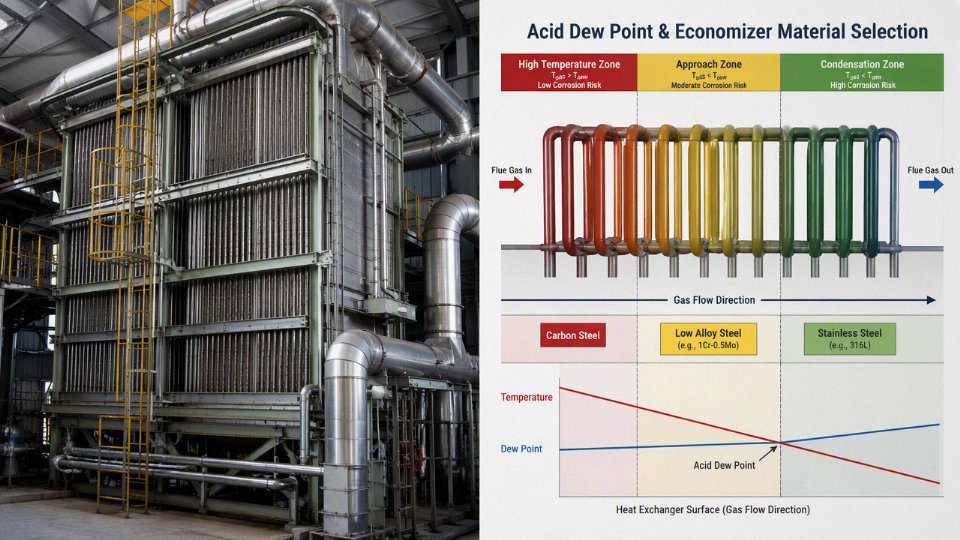
The sulfuric acid dew point in high-sulfur flue gas typically falls between 130°C and 160°C, depending on SO3 partial pressure and moisture content. This is not a soft number to be casual about. If your economizer exit gas temperature drops below the dew point — even intermittently during load swings or start-up — condensed sulfuric acid attacks carbon steel at rates that can eat through a 4 mm tube wall in under two years. Standard practice is to specify a minimum economizer exit gas temperature 15–25°C above the calculated acid dew point, which has the downstream consequence of leaving recoverable energy on the table. That’s an efficiency penalty you accept to protect the asset.
For low-temperature surfaces in moderate-sulfur duty, 09CrCuSbTi steel (the Chinese designation for what’s functionally equivalent to ND steel or SPA-H Corten-type alloy) provides meaningful corrosion resistance without the cost jump of austenitic grades. In severe duty — high SO3 concentration, temperatures cycling through the dew point regularly — the economizer bundle may need to step up to 304L or 316L stainless tubing, which roughly doubles material cost for that section.
09CrCuSbTi (ND steel) provides significantly better sulfuric acid dew point corrosion resistance than plain carbon steel Q235 in low-temperature economizer service.True
09CrCuSbTi contains copper, chromium, antimony, and titanium additions that form a dense protective patina under dilute sulfuric acid condensation, substantially reducing corrosion rate compared to unalloyed carbon steel at metal temperatures near or below the acid dew point. This is well-established in Chinese boiler engineering standards and corroborated by service data from coal-fired and industrial exhaust boilers.
HCl, Dioxins, and the Waste Incineration Duty
Municipal solid waste incineration and hazardous waste kiln applications bring a different acid gas problem: hydrogen chloride. The EU Waste Incineration Directive (WID), now consolidated into the Industrial Emissions Directive (IED) Annex VI, sets a daily average HCl emission limit of 10 mg/Nm³ at the stack — which is genuinely difficult to achieve without dedicated downstream treatment. At the WHRB itself, Cl⁻ concentrations in MSW flue gas can reach several hundred mg/Nm³ before any scrubbing, and at operating temperatures above roughly 450°C you’re also in the territory where dioxin and furan precursor compounds can re-synthesize on dust-laden tube surfaces if gas cooling is not managed correctly. The standard response is to design the WHRB to cool flue gas rapidly through the 250–450°C window — the so-called de novo synthesis zone — rather than allowing a slow temperature soak that favors PCDD/PCDF formation.
Scrubber placement matters enormously here. A dry or semi-dry scrubber (lime injection, typically) placed immediately downstream of the WHRB outlet requires an outlet gas temperature high enough — usually 160–220°C — to keep the reagent active and avoid condensation fouling in the injection zone. If you drop the WHRB outlet temperature too aggressively to maximize steam generation, you undermine scrubber performance. A wet scrubber, on the other hand, tolerates lower inlet temperatures and can handle higher Cl⁻ loads, but it introduces a wastewater treatment obligation and can cool the gas below the point where a downstream stack draft system works reliably without a reheater.
In some MSW line configurations, the WHRB functions partly as a quench cooler — prioritizing gas temperature control over steam generation rate — particularly in the first pass, with full steam-generating evaporator and superheater sections in subsequent passes once Cl⁻ and sticky-ash deposition risks are lower.
Material Selection Decision Framework
The choice of tube material across the three main heat transfer sections is driven by the intersection of operating temperature and Cl⁻/SO3 concentration. A simplified view:
| Section | Low Cl⁻ / Low SO3 | High SO3, Low Cl⁻ | High Cl⁻ (MSW/hazardous waste) |
|---|---|---|---|
| Superheater (>450°C) | T11 / T22 alloy steel | T22 or T91 | Inconel 625 cladding or 310S |
| Evaporator (250–450°C) | Carbon steel (SA-210) | Carbon steel + ND steel transition | 304L or SUS321 stainless |
| Economizer (<250°C) | Carbon steel | 09CrCuSbTi (ND steel) | 316L stainless or ND steel minimum |
These aren’t absolute rules — the actual specification depends on tube metal temperature calculations under your specific flue gas composition, not just nominal gas temperature, and on whether the surface sees periodic condensation during start-stop cycling. A plant running continuous 24/7 service in a cement kiln application can often stay on the lower-cost material longer than a two-shift operation where cold starts happen frequently. Capex savings from using plain carbon steel in the economizer can disappear inside three years if the operating profile wasn’t factored in honestly during design.
Particulate Matter and Dust Load Standards That Govern WHRB Inlet Conditions and Tube Bundle Design
Particulate regulation is where stack compliance and heat transfer engineering collide most visibly. The EU Industrial Emissions Directive sets PM stack limits at 10–20 mg/Nm³ for most combustion and process installations, with some waste incineration permits pushing that to 10 mg/Nm³ as a daily average. China’s GB 13271-2014 sits at 20–30 mg/Nm³ for general industrial boilers, dropping to 10 mg/Nm³ in designated ultra-low emission zones — which now covers a substantial share of eastern China’s industrial corridors. US EPA NSPS and PM NAAQS don’t typically set a single number for WHRBs across the board; the applicable limit depends on the source category, whether you’re under a New Source Review permit, and what state implementation plan applies. In practice, a cement plant in Texas and one in Bavaria are both chasing something in the 10–20 mg/Nm³ range at the stack, even if the regulatory path looks different.
Here’s the distinction that engineers sometimes miss in early project scoping: the stack emission limit is not the WHRB inlet dust loading. Those are entirely different quantities, and confusing them causes expensive redesigns. The stack limit is what exits the final treatment train. The WHRB inlet sees whatever the upstream process produces — and that number is orders of magnitude higher.
Cement kiln exhaust entering a WHRB carries 30–80 g/Nm³ of particulate, depending on kiln type, raw mix moisture, and whether a raw mill is in bypass. Non-ferrous smelters — copper converters, lead blast furnaces — typically deliver 5–20 g/Nm³. MSW incinerators, if the WHRB sits downstream of a primary electrostatic precipitator (which is common), will see roughly 2–8 g/Nm³. These aren’t nuisances. At 50 g/Nm³ and 300,000 Nm³/hr of flue gas, you’re moving something like 15 tonnes of dust per hour through the boiler. Tube pitch, fin geometry, and lane width between tube banks are all driven by that number.
For high-dust gas streams, bare tubes with wide transverse pitches (typically 90–120 mm center-to-center, depending on particle size and stickiness) are standard. Finned surfaces are largely out of the question above roughly 10–15 g/Nm³ — fins bridge with dust rapidly, and the apparent heat transfer gain disappears within days of commissioning. Extended surface area only makes sense once the gas has been cleaned to a level where fouling is manageable, usually in the back-end economizer section after a pre-dedusting stage.
Boiler orientation is a genuine design decision, not just a civil preference. Vertical downflow arrangements allow coarser particulate to fall clear of tube banks under gravity, which reduces bridging between passes and makes the boiler partially self-cleaning. Cement and ferrochrome plants have used this configuration for decades for exactly that reason. Horizontal arrangements are more compact and easier to integrate with existing plant steel, but they demand active cleaning — rapping mechanisms, acoustic sootblowers, or rotary sootblowers on a 4–8 hour cycle, shorter during high-load kiln periods or wet-process transitions. Skipping a cleaning cycle is the kind of shortcut that looks harmless until you pull the inspection hatch six months later.
Pre-dedusting equipment — settling chambers for coarser loads, high-temperature cyclones, or an upstream ESP — is increasingly written as a hard warranty boundary condition in WHRB purchase specifications. The boiler vendor guarantees thermal performance and tube erosion rates only up to a defined inlet dust concentration, say 5 g/Nm³ or 15 g/Nm³, and the civil/mechanical contractor is responsible for guaranteeing the pre-dedusting outlet meets that figure. Getting this boundary documented clearly in the EPC contract matters; ambiguous dust load responsibilities are a recurring source of warranty disputes on projects where actual kiln operation drifts from design conditions.
Continuous opacity monitors (COMS) are required on most major WHRB installations in the US and EU as a condition of operating permits, not just as optional best practice.True
US EPA 40 CFR Part 60 and Part 63 require COMS on many large combustion and process installations; EU IED Article 14 permit conditions routinely mandate continuous monitoring for particulate on installations above relevant capacity thresholds. The specifics depend on source category and permit, but COMS are a standard compliance instrument, not a discretionary upgrade.
Sampling port placement is a detail that gets overlooked until a Method 5 or EN 15259 stack test is scheduled and the test crew discovers the access ports are 0.3 m from an elbow. EPA Method 1 requires a minimum of 8 duct diameters downstream and 2 upstream of any flow disturbance for a valid traverse; EN 15259 has similar requirements with some flexibility for constrained installations. WHRB outlet ductwork and stack design should accommodate these distances from the start. Adding compliant access platforms and ports during construction costs very little. Retrofitting them into a finished stack with a test deadline looming costs considerably more, and a failed or contested stack test can trigger permit jeopardy.
CO2, Greenhouse Gas Accounting, and Carbon Trading Obligations Linked to WHRB Efficiency Targets
Carbon pricing has quietly become one of the harder constraints on waste heat recovery boiler specification. It’s not just about fuel savings anymore. In several industries — cement, steel, aluminum, float glass — a WHRB project now generates documented carbon obligations before the first weld is laid, and the efficiency number written into the datasheet directly affects how many allowances you surrender or earn at year-end.
EU ETS Phase IV and the Free Allocation Benchmark Trap
Under EU ETS Phase IV (2021–2030), free allowances for heat and steam production are benchmarked at roughly 57.8 tCO2/TJ of heat supplied — and that benchmark tightens by a linear reduction factor each year. A plant recovering waste heat through a WHRB to displace a gas-fired package boiler is, in principle, generating avoided emissions that either reduce the net allowances it must surrender or can be used to justify a higher allocation claim. At current EU ETS spot prices — which have traded in the €60–90/tonne CO2 range through much of 2023–2024 (price depends on energy market conditions and policy sentiment, so check current quotes) — recovering an additional 5,000–8,000 tonnes CO2/year through improved WHRB efficiency is worth roughly €300,000–720,000 annually in avoided allowance purchases. That’s not marginal.
The practical problem is that the benchmark applies to verified heat output, not estimated. Your MRV (monitoring, reporting, verification) plan has to show real steam enthalpy delivered, with calibrated instrumentation — flow meters, temperature transmitters, pressure sensors — all traceable and auditable. A WHRB with a poorly insulated steam drum and uncalibrated flow measurement will undercount heat recovery and understate your avoided emissions. That’s money left on the table, or worse, a compliance gap discovered during a third-party audit.
China National ETS: Baseline Factors and What the MRV Auditor Will Ask For
China’s national carbon market currently covers power generation, and is progressively incorporating cement, steel, and aluminum — exactly the sectors where WHRBs are most common. In these industries, a WHRB project is typically categorized under the facility’s overall carbon intensity calculation, with waste heat recovery credited as a reduction in the baseline emission factor. The baseline is calculated from the sector-specific emission factor (usually expressed in tCO2/unit of product — per tonne of clinker for cement, per tonne of crude steel for EAF plants) multiplied by actual production.
What this means operationally: the WHRB efficiency figure isn’t just a performance guarantee — it feeds directly into the MRV documentation package submitted to the provincial DRC or the national registry. Auditors will ask for design heat balance sheets, actual operating logs, and calibration records. In my experience, plants that specified a 78% WHRB to save capital and then tried to claim 85% efficiency in their carbon reports have had allowances clawed back. The numbers have to match, and they have to be defensible.
Adding an economizer section to a 10 t/h WHRB can raise thermal efficiency from roughly 78% to 88%, saving approximately 1,200–1,800 tonnes CO2 per year in fuel-equivalent displacement.True
The saving depends on fuel type displaced (natural gas vs. coal), steam parameters, and operating hours — typically 7,000–8,500 hours/year for continuous process industries. Higher-sulfur flue gases require acid dew point management on the economizer, which may limit the temperature approach and reduce the upper efficiency gain.
Steam Parameters and Carbon Intensity Per MWh
This is where the physics matters for procurement. A WHRB generating superheated steam at 5.3 MPa / 485°C can drive a back-pressure or condensing turbine at meaningfully higher Rankine cycle efficiency than one producing saturated steam at 1.6 MPa / 250°C. The carbon intensity per MWh of generated electricity drops — roughly speaking, you’re extracting more useful work from the same waste heat stream, which improves the avoided-emission case. Higher steam parameters cost more upfront: thicker drum walls, SA-335 P91 or equivalent alloy headers, tighter fabrication tolerances. But in a carbon-priced environment, that capex can pencil out in three to five years depending on the carbon price trajectory and grid emission factor in your jurisdiction.
The decision is not purely financial. Higher-pressure superheated steam systems carry more operational risk and require more rigorous water chemistry control. Plants without experienced boiler operators sometimes underestimate this.
What Should Be in Your EPC Contract
If you’re structuring an EPC for a WHRB project in a carbon-regulated market, three clauses are worth fighting for. First, explicit ownership of carbon credits generated by the waste heat recovery system — this is surprisingly often left ambiguous, creating disputes between plant owner and EPC contractor years later. Second, a defined MRV boundary: which instruments, which calculation methodology, which audit trail. Third, a thermal efficiency performance guarantee tied to a recognized test standard — ASME PTC 4.4 for heat recovery steam generators, or EN 12952-15 for water-tube boilers, depending on your market. Performance testing should happen at a defined operating load (typically 80–100% MCR) within six to twelve months of commissioning, with agreed remedies if the efficiency falls short. A 2–3% shortfall in thermal efficiency on a large WHRB can translate to several hundred additional tonnes of CO2 annually — real money, real compliance exposure.
Industry-Specific Emission Regulations for Key WHRB Applications: Cement, Steel, Glass, and Chemical Plants
Every industrial process dumps heat at a different temperature, carries a different cocktail of contaminants, and sits under a different regulatory framework. A WHRB specified for a cement kiln is not the same machine as one for an electric arc furnace, even if both happen to recover heat at nominally similar temperatures. Getting sector-specific regulation right at the front end of a project saves costly redesigns later.
Cement Plants: Alkali Dust, High Sulfur, and Tight PM Targets
The EU CLM BREF (revised 2020) sets BAT-associated emission levels of 200–450 mg/Nm³ for NOx, 50–200 mg/Nm³ for SO2, and a very tight 10–20 mg/Nm³ for particulates. Achieving that PM figure after the stack means the raw gas entering the WHRB is already carrying significant alkali-sulfate dust — typically 20–80 g/Nm³ depending on kiln type and raw meal composition — before any pre-dedusting cyclone upstream.
WHRBs on pre-heater tower exhaust typically see 300–380°C inlet temperatures; clinker cooler exhaust runs slightly cooler at 250–340°C but with coarser, abrasive dust. Both streams require wide-pitch bare tube bundles (not finned — fins blind off within weeks in high-dust cement service), and staggered arrangements are usually avoided in the first passes because bridging and erosion both get worse. Alkali condensation on tube surfaces below roughly 280–300°C is a real problem in cement gas: sticky deposits that harden overnight into a calcium-sulfate-alkali cement that no sootblower will touch. Minimum tube wall temperature control is not optional here.
Steel Plants: Sealed Pressure Design for CO-Rich Off-Gas
BOF and EAF off-gas WHRBs sit in a completely different regulatory and engineering category. The flue gas from a basic oxygen furnace is 60–70% CO — effectively a fuel gas at explosion-relevant concentrations. The EU Iron and Steel BREF mandates a final dust limit of 5–10 mg/Nm³, which is stringent, but the more pressing engineering constraint is the explosion risk of the gas itself.
These WHRBs must be designed as pressure-tight, gas-sealed vessels with calibrated explosion relief panels and continuous CO monitoring interlocked to emergency isolation dampers. A conventional natural-convection WHRB with inspection doors and atmospheric vents is simply not an acceptable design here. The capital cost premium for a sealed, positively pressurized WHRB with membrane wall construction and proper relief geometry is real — typically adding 15–30% to equipment cost depending on plant size — but it is not negotiable.
Glass Furnaces: Dew Point Management Drives WHRB Placement Strategy
Regenerative glass furnaces produce flue gas at 400–550°C carrying 200–500 mg/Nm³ SO2 and 500–800 mg/Nm³ NOx before any treatment. That’s a heavy multi-pollutant burden. The critical design question for WHRB placement is whether you install the unit before or after the SCR+FGD train.
Placing the WHRB upstream preserves high inlet enthalpy but exposes tube bundles to untreated SO2, which risks sulfuric acid dew point corrosion below about 160°C depending on SO3 concentration. Post-FGD placement means cooler, cleaner gas but often requires an additional reheater for SCR catalyst activation. In practice, the choice depends heavily on the glass type being produced — soda-lime glass uses a lot of sulfate fining agents, pushing SO2 much higher than borosilicate or specialty glass — and on whether the plant’s SCR catalyst operates at high-dust or low-dust configuration.
Sulfuric Acid and Chemical Plants: High-Temperature Service With PSM Overlay
Contact-process acid converters feed WHRBs at 900–1050°C — among the hottest inlets in any industrial WHRB application. The immediate concern is SO3 condensation. Below roughly 250°C tube wall temperature, SO3 and water vapor combine to form sulfuric acid that will destroy carbon steel or even standard austenitic tubes in months. Minimum wall temperature control through recirculation or controlled feedwater preheating is the standard solution, but it needs to be designed in, not bolted on later.
These plants also fall under OSHA PSM (29 CFR 1910.119) and EPA RMP (40 CFR Part 68) in the United States, or their national equivalents elsewhere. A WHRB in sulfuric acid service is classified as a pressure vessel in hazardous chemical service, which triggers formal process hazard analysis, relief valve sizing per specific reactive-chemistry scenarios, and third-party inspection requirements that add meaningful schedule time to a project. EPC teams that treat this as a standard utility boiler procurement invariably hit compliance issues late in the project.
MSW and Hazardous Waste Incineration: The Strictest Multi-Pollutant Regime
EU Industrial Emissions Directive Chapter IV (successor to Waste Incineration Directive 2000/76/EC) mandates a dioxin/furan limit of 0.1 ng TEQ/Nm³ and a mercury limit of 0.05 mg/Nm³ for waste incineration plants.True
These limits are established in IED Annex VI, Part 3, and are consistent with the original WID 2000/76/EC requirements that were absorbed into the IED framework.
The WHRB in a waste incineration plant is not simply recovering heat — it is performing a rapid thermal quench that is itself a pollution control function. Flue gas must drop from the post-combustion chamber exit (minimum 850°C, held for at least 2 seconds per IED requirements to destroy organics) to below 200°C as quickly as possible through the boiler, specifically to prevent dioxin and furan re-synthesis in the 250–450°C temperature window where de-novo formation is thermodynamically favored.
This means the WHRB is sized and arranged to maximize cooling rate, not just heat extraction efficiency. Membrane wall construction is standard. The tube bundle geometry, flue gas velocity (usually 5–8 m/s through the convection passes), and sootblower frequency are all tuned around the temperature-time profile, not purely around thermal output. Grate corrosion from HCl is severe, and superheater tube materials in MSW service routinely step up to Alloy 625 overlay or Inconel-clad tubes at a significant cost premium — justified by the operating environment, not by any conservative overspecification.
The diversity across these sectors is the point. A procurement team sourcing a WHRB on specification alone, without mapping the applicable regulatory framework and process gas chemistry first, is working from an incomplete brief.
Continuous Emission Monitoring Systems (CEMS) Requirements and How They Define WHRB Instrumentation Scope
Most EPC teams treat CEMS as a commissioning afterthought — something the controls subcontractor bolts on in the final weeks before handover. That is a mistake that costs real money, and I’ve seen projects where the ductwork had to be partially re-routed because nobody reserved straight-run distance for the analyzers until the civil steel was already erected.
Regulatory Mandates Driving the Monitoring Obligation
The three frameworks that come up most often in international WHRB projects are EU IED Article 70, US EPA 40 CFR Part 75, and China’s HJ 76-2017 standard.
EU IED Article 70 requires continuous monitoring for plants above 50 MWth — which catches a large proportion of industrial WHRB installations in cement, steel, and glass. The parameters are not optional: O₂, CO, NOx, SO₂, total particulate matter, volumetric flow, flue gas temperature, and moisture content all have to be reported continuously, with valid data availability of at least 90% annually. Miss that threshold and the regulatory agency may treat the missing periods as exceedances.
US EPA 40 CFR Part 75 is particularly demanding around substitute data procedures. When the CEMS goes offline — for calibration, sensor failure, or a maintenance outage — the regulation prescribes specific conservative default values that apply to every hour of missing data. Those substitute values are almost always worse than actual measured emissions, so every unplanned CEMS outage effectively inflates your reported annual tonnage. The practical consequence: WHRB planned maintenance windows need to be coordinated with the CEMS availability calendar from day one of O&M planning, not improvised later.
China HJ 76-2017 is the national technical specification for fixed-source CEMS, covering analyzer performance, QA/QC protocols, data transmission, and the interface to provincial environmental monitoring platforms. Plants in key emission control zones face tighter audit cycles.
Analyzer Placement and Ductwork Geometry
This is where the instrumentation obligation bites the hardest in terms of civil and structural design. Extractive CEMS systems draw a continuous gas sample through a heated probe and heated sample line — typically maintained at 120–180°C to prevent condensation of SO₃ and moisture — back to a remote analyzer shelter. The probe nozzle location on the stack breeching needs to be at a point of representative flow mixing, which usually means downstream of any last bend or obstruction by at least 8–10 duct diameters of straight run. On a 2-meter-square duct, that’s 16–20 meters of unobstructed duct — space that simply doesn’t exist if the P&ID was drawn without CEMS in mind.
In-situ cross-duct analyzers (common for opacity/dust monitoring via transmissometer, and for some O₂/CO sensors) have the same straight-run requirement and add another constraint: you need access platforms on both sides of the duct, structural supports for the sender and receiver heads, and a continuous instrument air or purge air supply to keep the optical windows clean. On a dusty WHRB application — say, a rotary kiln off-gas unit — purge air flow rates of 15–30 Nm³/h per transmissometer are typical, and that has to come from somewhere.
CEMS straight-run distance requirements of 8–10 duct diameters must be reflected in WHRB ductwork layout at the P&ID stage, not during commissioning.True
This is mandated by analyzer manufacturer installation specifications and is consistent with EPA Method 1 and EN 15259 sampling location selection criteria, both of which require representative flow conditions that can only be achieved with sufficient upstream straight run.
Data Availability, Downtime, and Maintenance Coordination
The 90% valid data capture requirement under EU IED sounds achievable until you account for daily calibration checks, quarterly linearity audits, annual relative accuracy test audits (RATAs under 40 CFR Part 75), and any unplanned sensor failures. In practice, a well-maintained CEMS system on a WHRB running 8,000 hours per year will consume roughly 200–350 hours annually in planned QA/QC activities alone. That leaves a narrow margin before you breach the 90% threshold.
The implication for WHRB operators: sootblower outages, tube bundle inspections, and economizer cleaning schedules all have to be planned around CEMS operational windows, not the other way around. Some plants run a dual-analyzer configuration — one online, one on standby — to cover maintenance without triggering substitute data periods, though that adds roughly 30–50% to the CEMS capital cost.
Integration with DCS, SCADA, and Regulatory Reporting Platforms
Every CEMS installation I’ve reviewed that caused regulatory trouble had the same root problem: the data never made it reliably from the analyzer to the reporting platform. The WHRB EPC scope needs to include, explicitly, the communication protocol between the CEMS data acquisition system and the plant DCS — Modbus RTU is still common on older plants, but OPC-UA is increasingly specified on new builds and is far more robust for this application. From the plant DCS or a dedicated CEMS data historian, the data pathway continues to the national regulatory platform: China’s pollution source monitoring and management platform, the EU’s E-PRTR reporting chain, or the US EPA’s ECMPS electronic submission system.
Data historian specification matters more than most procurement teams realize. Regulatory agencies audit the raw 1-minute averages, not just the hourly or daily rolled-up values. Storage architecture and data integrity (timestamps, audit trails, no editable records) need to be defined in the instrumentation specification, and verified during pre-commissioning, before the plant accepts a single hour of regulatory responsibility.
How to Build a Regulation-Driven WHRB Selection Matrix: A Step-by-Step Engineering Checklist
Most WHRB projects that run into permitting problems late in execution share a common failure point: the regulatory homework was treated as someone else’s job. Engineering did the thermal sizing, procurement chased prices, and nobody compiled a single document listing every applicable limit before the technical inquiry went out. The checklist below is designed to prevent exactly that.
Step 1 — Regulatory Inventory Before You Write a Single Spec Line
Pull every applicable permit — national, regional, local — and list the stack emission limits, fuel type restrictions, and any technology mandate such as BAT conclusions under the EU IED or a BACT determination under a US Prevention of Significant Deterioration permit. Some jurisdictions layer requirements: a cement plant in a Chinese key emission control zone may face GB 4915 sector limits and a provincial ultra-low emission requirement that’s stricter than the national standard. Both apply. Procurement managers especially tend to anchor on national standards and miss the local overlay — that’s where surprises live.
Step 2 — Process Gas Characterization Package
This is the foundation document for any credible quotation. You need inlet gas flow in Nm³/h, temperature range (design maximum and sustained normal), pressure or draft, and full composition: CO, CO₂, SO₂, NOx, HCl, dust loading (g/Nm³), heavy metals if present, and moisture fraction. Provide both worst-case and normal operating ranges — vendors who quote on nominal-only data will almost certainly undersize the sootblower system or select inadequate tube materials for acid dew-point conditions. A kiln bypass gas stream can swing 80°C in temperature and double its dust loading during production upsets. If you don’t document the range, the vendor designs for the middle.
Step 3 — Emission Control System Boundary and Guarantee Points
Decide early whether you’re specifying a WHRB-only scope or an integrated package: WHRB + SCR + dry/wet FGD + bag filter. This affects both the bid structure and accountability for compliance. Define explicit inlet and outlet emission guarantee points, and name the test methods — EPA Method 7E for NOx in US projects, EN 14792 for European stacks, HJ 692 in China. Vague specs like “meets local NOx limits” produce vague guarantees that dissolve at the performance test.
Step 4 — Steam Parameters vs. Carbon Accounting
Higher steam pressure and temperature generally improve thermal efficiency and carbon credit yield, but they also push you into higher material grades and thicker pressure parts. For most industrial WHRB applications recovering flue gas at 400–750°C, steam conditions in the 1.6–6.5 MPa / 250–480°C range cover the bulk of real-world projects; pushing above that needs a clear economic justification from the carbon credit or process steam value. Check which pressure vessel code has jurisdiction — ASME Section I, EN 12952, or China GB/T 16507 — before selecting design pressure, because code jurisdiction affects wall thickness calculations, inspection hold points, and ultimately delivery schedule.
Step 5 — Material and Code Compliance Matrix
Map the flue gas corrosion environment to tube and pressure part materials systematically. SA-213 T11 handles moderate sulfidation; T22 and T91 are appropriate for higher temperatures; 310S or Incoloy 825 enters the picture with aggressive chloride or high-sulfur streams. Specify the design code on the inquiry — a vendor shipping an ASME-stamped WHRB into a PED 2014/68/EU jurisdiction will trigger re-inspection or re-certification costs that usually fall on the buyer.
SCR catalyst life in a WHRB application typically runs 16,000–24,000 operating hours before activity drops below the guaranteed NOx reduction efficiency.True
This range is consistent with published catalyst supplier data and operational experience across ammonia-SCR systems in cement and glass WHRB installations; actual life depends heavily on inlet dust loading, SO₃ concentration, and catalyst pitch selection.
Step 6 — Vendor Qualification Criteria
Ask for third-party emission test reports from reference installations in your target regulatory jurisdiction, not factory acceptance test data alone. CEMS integration track record matters: a vendor who has never commissioned a CEMS-linked DCS handoff in an EU or US-permitted plant will introduce integration risk you’ll absorb. Documented EPC delivery — including flue gas treatment, stack, and permit closure — is worth more than a price advantage of 5–8% on the WHRB itself.
Step 7 — Lifecycle Cost Model Over 20 Years
Capital cost is usually 30–45% of the 20-year total cost of ownership once you fold in CEMS operation and maintenance (roughly €15,000–40,000 per year depending on analyzer count and local service rates), SCR catalyst replacement cycles, sootblower steam consumption, and tube bundle inspection outages. Carbon cost projections are uncertain, but even at conservative EU ETS allowance prices, a 3–4 percentage point difference in WHRB thermal efficiency compounds significantly over two decades. Run the NPV comparison across at least two competing configurations before awarding — plants that skip this step routinely discover they bought the wrong efficiency tier.
Frequently Asked Questions About Emission Regulations and Waste Heat Recovery Boiler Selection
Does a WHRB itself require an emission permit, or does the upstream process cover it?
This depends on whether the WHRB fires supplemental fuel. In most jurisdictions — EU member states under the Industrial Emissions Directive, U.S. state Title V programs, and China’s pollutant discharge permit system — a pure heat-recovery boiler with no auxiliary combustion is treated as part of the upstream process unit. The facility permit covers it. Stack emissions are attributed to the source process (the kiln, furnace, or reformer), not the boiler separately.
The moment you add duct burners to boost steam output during low-load periods, the regulatory picture changes. Duct burners are classified as combustion sources in their own right once they cross capacity thresholds — typically 10 MMBtu/hr under EPA rules, or the IED’s 1 MW thermal input boundary in Europe. That triggers standalone permitting, CEMS obligations, and potentially BACT/LAER review depending on the attainment status of the site’s airshed. This catches procurement teams off guard surprisingly often, especially on projects where duct burners were added late in the design phase to satisfy a steam balance.
A WHRB with no auxiliary burners is not independently subject to combustion source permitting in most major regulatory frameworks.True
Regulators treat unfired waste heat recovery boilers as process equipment; emission obligations flow from the upstream combustion or industrial process. Auxiliary duct burners, however, create a new combustion source that must be declared and permitted separately once they cross capacity thresholds under EPA, EU IED, or equivalent national rules.
Can a single WHRB design satisfy both EU IED and China GB standards for an export or dual-destination project?
Yes, routinely. The engineering approach is straightforward: identify the stricter limit on each pollutant parameter between the two regimes, and design to that limit across the board. For NOx, EU IED’s 100–200 mg/Nm³ range and China’s ultra-low emission requirements (roughly 50 mg/Nm³ in key control zones) mean you size SCR catalyst volume for the Chinese standard and the EU compliance follows automatically. For SO2 the same logic applies.
Dual-standard projects do cost more. Expect the combined WHRB plus air pollution control system to run roughly 5–12% higher than a single-jurisdiction design, depending on how far apart the two regulatory regimes are for the specific pollutants and how much additional catalyst, scrubber volume, or structural steel is needed. That range is wide because it depends heavily on inlet gas composition and the gap between the two sets of limits. If the project’s process gas is relatively clean, the premium is at the low end. High-sulfur or high-dust applications can push toward the top.
What is the minimum inlet gas temperature that justifies integrating an SCR reactor into the WHRB gas path?
SCR catalyst activation is temperature-sensitive. Vanadium-titanium catalysts — still the most common formulation in industrial WHRBs — require flue gas temperatures in the 300–400°C range. Zeolite-based and base-metal catalysts can work down to roughly 280°C under controlled conditions, but you pay a catalyst cost premium and face faster deactivation if the gas carries sulfur species. Above about 420°C, standard catalyst starts to sinter and lose surface area.
If your WHRB inlet sits at 600°C or higher (common in cement clinker coolers or steel reheat furnace exhaust), the SCR window lands naturally somewhere in the middle of the tube bundle. That’s actually a good arrangement — the gas has already shed enough enthalpy to hit the catalyst temperature range, and you avoid reheating costs.
Where this gets expensive is when the process gas arrives at the WHRB inlet already below 280°C, or when the economizer pulls the gas below the SCR window before the catalyst section. In those cases you either accept a tail-end SCR with a flue gas reheater, or live without SCR entirely and rely on primary combustion controls. Reheating is not trivial — it typically consumes 3–6% of the recovered steam energy, which directly erodes the project’s heat recovery economics. Worth modeling carefully before committing to the layout.
How do I specify a WHRB for a process that will face stricter emission limits in 3–5 years?
Design the physical envelope and structural steel for the anticipated future equipment, not just today’s requirement. That means sizing the duct cross-sections and casing dimensions to accommodate an additional SCR catalyst module or a larger scrubber vessel. It costs relatively little at fabrication — maybe 3–8% more structural steel — and saves enormously compared to retrofitting a congested gas path later.
Install CEMS sampling ports and instrument taps during initial construction even if the monitoring obligation does not yet apply. The ports cost almost nothing to weld in; cutting them into an operating duct later involves hot-work permits, production shutdowns, and far more hassle than the hardware itself. Choose tube pitch and sootblower coverage for worst-case dust loading rather than current process conditions — if the upstream process changes or a bag filter upstream is bypassed temporarily, you want the boiler tube bundle to handle it without fouling into a performance hole.
What performance guarantees should I require from a WHRB supplier on emission compliance?
Require guaranteed stack emission concentrations — actual mass concentrations in mg/Nm³, referenced to a defined O₂ basis and dry/wet condition — measured under specified inlet gas conditions and verified by a named test method. EPA CTM-030, EPA Method 7E, or EN 14792 for NOx are the typical references depending on jurisdiction. The test conditions (inlet temperature range, mass flow, dust loading) need to be bounded in the contract; a supplier should not be allowed to test only at the most favorable operating point and call it a compliance demonstration.
Do not accept “design basis guarantee” language. That formulation means the supplier is guaranteeing their calculation inputs, not the output you actually need to present to a regulator. Require liquidated damages tied to measured stack concentrations. Suppliers who push back hard on this are usually uncertain about their air pollution control integration — which tells you something worth knowing before you award the contract.
How does mercury regulation affect WHRB design in coal-based process industries?
EPA MACT under 40 CFR Part 63 Subpart UUUUU and EU IED mercury limits — typically 0.02–0.05 mg/Nm³ depending on the facility category — require activated carbon injection upstream of the fabric filter or ESP. The critical detail for WHRB design is temperature. Activated carbon adsorbs mercury most effectively in the 120–180°C range. Too hot and adsorption efficiency drops sharply; too cold and you risk acid condensation on the carbon and downstream equipment.
That 120–180°C window directly governs where you set the economizer outlet temperature. If your economizer is optimized purely for heat recovery, it might pull flue gas down to 110°C or even lower, which is too cold for reliable ACI performance and risks sulfuric acid dew point corrosion anyway. In practice, WHRB economizer outlet temperatures for coal-derived gas streams with mercury compliance requirements usually land at 130–160°C as a deliberate design target, not the theoretical minimum. That costs you a few percentage points of recoverable enthalpy, but it keeps the ACI system in its effective window and protects the downstream bag filter from acid attack.
References
Stationary Combustion Turbine Standards — 40 CFR Part 60, Subpart KKKK — Electronic Code of Federal Regulations
New Stationary Combustion Turbine Standards — 40 CFR Part 60, Subpart KKKKa — Electronic Code of Federal Regulations
EPA Requirements for Stationary Gas and Combustion Turbines — U.S. Environmental Protection Agency
Industrial Boiler and Process Heater Hazardous Air Pollutant Standards — U.S. Environmental Protection Agency
Prevention of Significant Deterioration Air Permit Requirements — U.S. Environmental Protection Agency
Title V Operating Permits for Stationary Emission Sources — U.S. Environmental Protection Agency
Continuous Air Emissions Monitoring Requirements and Methods — U.S. Environmental Protection Agency
Non-Hazardous Secondary Material and Solid-Waste Classification Rules — U.S. Environmental Protection Agency
EU Industrial and Livestock Rearing Emissions Directive Requirements — European Commission
EU Best Available Techniques Conclusions for Large Combustion Plants — EUR-Lex