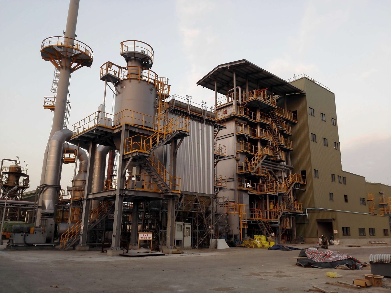
Biomass boiler projects fail at commissioning more often than most people in procurement like to admit. The fuel handling jams, the refractory cracks during first firing, the flue gas readings blow past permit limits on day one — and suddenly an 8-week startup stretches to five months while the plant bleeds demurrage, penalty clauses, and the cost of running a backup oil burner at three times the fuel price. Getting the installation and commissioning sequence right is not a matter of following a generic checklist; it requires engineering decisions made in the right order, with the right dependencies understood before concrete is poured or a single flange is bolted up.
Best practices for industrial biomass boiler installation and commissioning cover four interdependent phases: civil and structural readiness, mechanical erection and refractory curing, cold and hot functional testing, and load-step acceptance against fuel, emission, and efficiency targets. Done correctly on a 10–75 t/h steam boiler, the process runs 8–16 weeks from verified site readiness to full-load sign-off — longer if fuel quality is inconsistent or flue gas treatment is undersized.
What makes biomass harder than coal or gas is the fuel itself. Moisture content, particle size distribution, ash fusion temperature, and chlorine levels all shift with season, supplier, and storage time — and every one of those variables reaches back and changes how you set up the grate, size the induced-draft fan, and tune the combustion air staging. The installation decisions you make in week two will either give you stable, efficient combustion at 85–90% thermal efficiency or hand your operators a boiler that hunts, clogs, and corrodes. The difference is knowable in advance.
Site Assessment and Civil Foundation Requirements for Biomass Boiler Installation
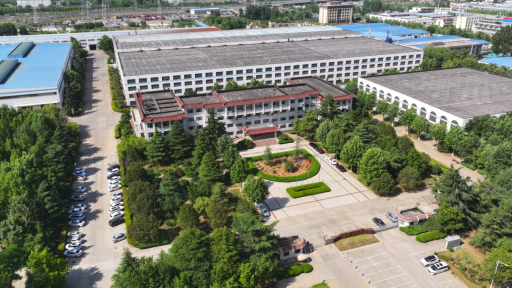
Before the first structural steel arrives on site, you need a clear picture of what’s under your feet and around your plot boundary. Skipping or rushing this phase is how projects end up with cracked pedestals six months after startup, or with a bag-house filter wedged so close to a property line that you can’t swing a wrench to change a bag row.
Soil Bearing Capacity and Foundation Design
For industrial biomass boilers in the 10–75 t/h steam output range, a typical combined boiler-steel-structure-and-refractory load lands somewhere between 80 and 250 tonnes on the foundation, depending on boiler type, drum configuration, and how much of the fuel-feed and ash-handling steel ties back to the same slab. CFB biomass units carry additional dynamic load from the circulating bed material and the cyclone separator — in practice the cyclone alone on a 35 t/h unit can add 15–30 tonnes, often cantilevered off a mid-height steel frame, which creates an eccentric moment the civil designer needs to see early.
Minimum allowable soil bearing capacity is usually 120–150 kN/m² for stoker-fired (traveling-grate) units in the 10–35 t/h range, stepping up to 180–250 kN/m² for larger or CFB configurations. If site investigation returns values below those thresholds — which is common on reclaimed industrial land in coastal or riverine areas — you’re looking at driven pile or bored-pile foundations. Pile depth varies widely (8 m to 25 m is a realistic range) depending on local geology, water table, and seismic zone. Get the geotechnical report before you finalize the equipment purchase contract, not after. Resequencing foundation work after delivery adds 6–12 weeks and real cost.
Traveling-grate boilers generate low-frequency vibration through the grate-drive mechanism. Vibration isolation pads rated at the correct natural frequency (typically targeting ≥15 Hz separation from the excitation frequency) should be specified at the boiler feet — this is often forgotten in local fabrication scope and becomes a dispute item during commissioning.
Clearance Envelopes and Maintenance Access
Code minimums and practical maintenance are not the same number. Chinese GB 50041 requires roughly 1.5 m clear on the firing-side and 1.0 m on the rear and sides for boilers under 35 t/h; above that, expect 2.0–3.0 m firing-front clearance for traveling-grate units. CFB units need additional space around the external cyclone separator — at minimum 1.2 m for insulation cladding access, more if the refractory is monolithic cast and needs scaffolding for periodic inspection.
The bag-house filter is where I see clearance consistently under-budgeted. Allow a clear lane of at least 2.5 m along the full filter length for bag-pull access, plus headroom above the filter housing equal to bag length plus roughly 1.0 m for the lifting fixture. Ignoring this means cutting structure later.
Utility Tie-In: Water, Air, and Power
Make-up water quality is non-negotiable. Per GB/T 12145 and broadly consistent with ASME guidelines for low-to-medium pressure steam boilers (1.0–3.8 MPa), hardness should be below 0.03 mmol/L after softening, chloride content under 50 mg/L, and dissolved oxygen below 0.05 mg/L at the boiler inlet — achievable with a properly sized deaerator and ion-exchange softener train. Feed water that misses these targets doesn’t just scale the tubes; it causes pitting corrosion that shortens drum life and voids most manufacturer warranties.
Compressed air for soot-blowing and instrumentation on an industrial biomass boiler should be supplied at 0.5–0.7 MPa with a dew point below −20 °CTrue
Moisture in instrument air causes valve positioner failure and soot-blower nozzle corrosion; these pressure and dew-point values align with standard ISA and GB instrument air quality specifications for industrial boiler auxiliaries.
Electrical supply should match the motor control center specification — typically 380 V / 50 Hz for Chinese-built plant, 400 V / 50 Hz for EU-market projects, with a dedicated earthing grid resistance below 4 Ω for the boiler island. Don’t assume the site’s existing earth grid is adequate; measure it.
Stack Height and Draft Calculations
Natural draft on a biomass boiler depends on stack height, internal diameter, average flue-gas temperature, and local elevation above sea level. A rough working target is 15–25 Pa of available draft per 10 m of stack height at rated load, but this degrades at high-altitude sites (above roughly 1 500 m) and in summer ambient conditions where the temperature differential between flue gas and ambient narrows. For most 10–75 t/h installations, stack heights of 35–60 m are typical, though environmental permit dispersion modeling — required under EU IED and most national permitting regimes — may push that higher depending on surrounding terrain and residential proximity. Lock in the environmental permit conditions before the stack is fabricated. Changing a stack height after manufacture is straightforward; changing it after it’s erected is painful.
Fuel System Design and Biomass Handling Equipment Integration
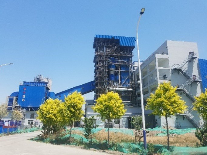
Get the fuel system wrong and no amount of careful boiler commissioning will save you. This is the section most EPC proposals underspecify, and it’s where a disproportionate share of first-year operational failures originate.
Fuel Characterization Is Not Optional
Biomass is not a single fuel. Wood chips from a sawmill in northern Europe and rice husks from a Southeast Asian mill are both called “biomass,” but they behave almost nothing alike in a combustion system. Before anyone specifies a screw feeder diameter or a grate area, you need a fuel characterization matrix — and it needs to reflect the actual fuel you’ll receive at the gate, not a textbook average.
Typical ranges that matter for system sizing:
| Fuel Type | Moisture (% ar) | LHV (MJ/kg ar) | Bulk Density (kg/m³) | Ash Content (% db) |
|---|---|---|---|---|
| Wood chips (forest) | 30–55% | 7.5–11 | 180–320 | 0.5–2% |
| Rice husk | 10–14% | 12–14 | 90–130 | 18–22% |
| Bagasse | 45–55% | 7.5–9.5 | 120–200 | 2–5% |
| Palm shell | 12–18% | 16–18 | 550–700 | 2–4% |
| Straw pellets | 8–12% | 14–16.5 | 550–700 | 4–8% |
LHV and moisture stated on as-received basis; ash content on dry basis. Actual values depend on origin, season, and storage duration.
These numbers directly size three things: the required fuel mass feed rate to hit your boiler’s rated output, the grate area or fluidized bed cross-section needed to maintain stable combustion intensity, and the storage volume to buffer fuel supply gaps. A 20 t/h steam boiler running on 50%-moisture bagasse needs roughly twice the volumetric fuel throughput compared to the same unit on palm shell — same boiler nameplate, very different fuel handling footprint.
Biomass fuel moisture content has no significant effect on fuel feed rate sizingFalse
Moisture content directly reduces the as-received lower heating value and increases the required mass feed rate. A shift from 15% to 50% moisture on wood chips can reduce LHV by roughly 40%, requiring proportionally higher feed rates and larger storage to maintain full-load output.
Storage and Reclaim Layout
Covered storage capacity should target a minimum of 3–7 days of full-load consumption. The lower end applies when you have reliable daily delivery logistics; the upper end is appropriate for seasonal feedstocks — straw, bagasse, rice husk — where supply can be interrupted. Undersized live storage is one of the most common design shortcuts, and it forces operators to run at derated load every time supply logistics hiccup.
Biomass silos and bunkers require active fire suppression — CO detection combined with water deluge or inert gas injection at a minimum. High-moisture materials like fresh bagasse are prone to spontaneous heating during storage, particularly in warm climates or when piles exceed 4–5 meters in depth without aeration.
Reclaim conveyor slope is a detail that gets ignored until the fuel stops moving. For high-moisture, fibrous feedstocks (bagasse, straw, wet wood chips), belt conveyor slopes above roughly 18° cause slippage and bridging. Screw conveyors can handle steeper angles but are sensitive to oversize pieces and tramp metal — a single bolt from a harvester can seize a screw in a 200mm tube and take two hours to clear at exactly the worst moment.
Feeding System Selection
The feeding system choice depends on fuel type, boiler capacity, and furnace pressure class:
Screw feeders suit granular, relatively dry fuels (pellets, husks, palm shell) at capacities up to roughly 10–15 t/h per feeder. They’re reliable when properly sized, but fibrous or wet fuels wrap around the flights and jam.
Rotary valves (rotary airlocks) are appropriate where the furnace operates under slight positive pressure or where you need a reliable pressure break between the fuel chute and the firebox. Typical on stoker units above 20 t/h.
Spreader-stoker spouts with pneumatic injection distribute fuel across the grate evenly and handle a wider particle size range than screw systems. For large grate areas (>15 m²), you typically need multiple spout positions — two or three per width — or you get cold corners and uneven burnout.
Pneumatic injection is used for fine, low-density fuels like rice husk where gravity feeding produces channeling. The air volume introduced by pneumatic injection must be accounted for in the combustion air balance; miss this in design and you’ll fight excess air control from day one.
Combustion Control Interlocking
The fuel feed system and the boiler combustion control system must be tightly interlocked — not loosely coordinated via operator intervention. In practice, this means the fuel feed rate signal follows the boiler master pressure controller output, with hard limits on feed rate step-change ramp rates. Without ramp limiting, a sudden load increase command dumps excess fuel onto the grate before the combustion air system responds, causing a CO spike and often a furnace pressure excursion that trips the induced draft fan on high-pressure interlock.
Fuel pile-up on traveling grate stokers is a specific failure mode worth calling out. If the grate speed control loses synchronization with the fuel feed rate — even briefly — you get a deep fuel bed that starves air penetration, generates incomplete combustion, and can cause a localized gas explosion when the accumulated CO ignites. The interlock logic should include grate speed feedback as a permissive for fuel feed, not just furnace draft pressure.
In my experience, plants that invest in commissioning the fuel feed control loops carefully — tuning the feed rate PID, verifying all interlock setpoints under real fuel, not simulated signals — consistently hit stable operation within 4–6 weeks of first fire. Plants that treat the fuel system as a mechanical-only scope and bolt on the controls as an afterthought are still fighting CO trips six months later.
Combustion System Erection: Grate, Furnace, and Pressure-Part Installation Sequence
Getting the combustion system erected in the right order — and with the right hold points enforced — is where projects either earn their commissioning timeline or start hemorrhaging it. Skipping a tolerance check on day three of grate assembly has a way of showing up as uneven bed temperatures six months into operation, by which point the root cause is buried under ash and denial.
Traveling-Grate and Water-Cooled Vibrating-Grate Assembly
Grate installation should start from the centerline reference established during civil handover. Lateral bar alignment must be held within ±1 mm deviation across the full grate width — tighter than it sounds when you’re working with grate sections spanning 3–5 m and fitters who are used to structural tolerances an order of magnitude looser. Check this with a precision level and steel wire reference, not just a spirit level balanced on a grate bar. Drive shaft leveling is a mandatory hold point; any residual twist in the shaft will transmit into uneven bar travel, creating high-wear zones on one side and channeling combustion air on the other.
Refractory castable on side walls and grate frame must cure before first fire — typically 48–72 hours air cure followed by a controlled bake-out schedule that steps from ambient up to around 300–350 °C over at least 24 hours, then to operating temperature over another 12–16 hours. Rush this and you get steam-induced spalling in the first week. Some contractors treat the bake-out as a formality; that attitude is expensive.
Drum and Header Installation: Rigging, Hydrostatic Testing, and Weld Inspection
Drums on industrial biomass boilers in the 10–75 t/h range typically run 8–35 tonnes per shell, depending on design pressure and length. Rigging plans must be stamped and reviewed before the crane is even mobilized — not the morning of the lift. Lift points are pre-welded lugs designed into the drum; improvising with chain slings around a drum shell is a rejection offense and a safety hazard.
Hydrostatic testing is conducted at 1.25× design pressure per ASME Section I or GB 150, whichever governs your jurisdiction and client specification. Hold time at test pressure is usually 30 minutes minimum; any visible weep or pressure decay beyond the allowed tolerance requires depressurization, repair, and retest — no exceptions.
Weld inspection coverage depends on the joint category and code. For Class I longitudinal seams on drums, 100% radiographic or UT coverage is standard. Circumferential seams typically require a minimum of 10–25% spot radiography under GB 150 for lower-pressure classes, but clients on EU-destined or export projects often specify 100% UT on all pressure-retaining welds regardless, and frankly that’s the right call for a biomass unit where thermal cycling from fuel variability is a real long-term fatigue consideration.
Hydrostatic test pressure for industrial boiler pressure parts must be 1.25× design pressure per ASME Section I and GB 150True
Both ASME Section I (PG-99) and the Chinese pressure vessel standard GB 150 specify a hydrostatic test pressure of at least 1.25 times the maximum allowable working pressure for boiler pressure parts, applied to verify weld integrity and structural soundness before commissioning.
Membrane Wall Panel Erection and Expansion Management
Membrane wall panels are erected from the bottom headers upward, with each panel section aligned to the furnace centerline before welding to the next. Expansion joints between panel sections are not optional details — the furnace grows 15–25 mm vertically on a mid-sized unit from cold to full operating temperature, and if the casing is welded rigid against that movement, you’ll see casing hot-spots develop within a few months as the insulation compresses and the outer plate buckles. Hot-spots on the casing exterior run the corrosion risk that most operators underestimate until they’re looking at a 12 mm plate that has thinned to 6 mm.
Insulation installation sequence matters: mineral wool or calcium silicate block goes in with staggered joints, casing panels close last, and all penetrations get flexible sealing. A small gap left at a thermocouple penetration sounds trivial; it becomes a sustained air infiltration point that skews O₂ readings and confuses the combustion control system.
CFB-Specific Considerations: Cyclone, Loop-Seal, and Bed Material
For CFB biomass boilers, cyclone separator alignment is tighter than most civil contractors expect. The cyclone inlet duct centerline must align with the furnace exit within a few millimeters — misalignment causes asymmetric particle loading, accelerated wear on one side of the cyclone barrel, and reduced separation efficiency that directly raises particulate loading on the downstream bag-house filter.
Loop-seal refractory lining is typically 200–250 mm of high-alumina castable, installed and cured to the same bake-out schedule as the furnace refractory. Underthickness here is a failure waiting to happen: the loop-seal operates at 800–900 °C with abrasive circulating bed material, and a 150 mm lining that should be 220 mm will fail within one operating season.
Bed material specification is a procurement detail that gets treated as an afterthought and shouldn’t be. Silica sand with d50 in the 0.2–0.4 mm range and a rounded particle morphology is the standard starting charge. Angular crusher dust looks similar in a bag but produces higher attrition rates and faster refractory wear. Specify the gradation curve and source it before commissioning, not during.
Auxiliary Equipment Commissioning: Feed Water, Air, Ash, and Flue-Gas Systems
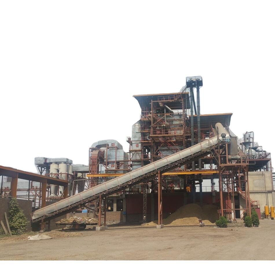
Most project delays I’ve seen in biomass boiler startups don’t originate at the boiler itself. They come from auxiliary systems that got treated as afterthoughts — the feed water skid commissioned two days before light-off, the ID fan wired but never curve-tested, the bag-house filter handed over without an integrity check. By the time integrated firing begins, you’re troubleshooting five things at once under schedule pressure, which is exactly when mistakes become expensive.
Feed Water System Pre-Commissioning
Get the deaerator running and stable before anything else. The dissolved oxygen (DO) target at the deaerator outlet is less than 7 µg/L; in practice, most well-tuned thermal deaerators with proper steam-sparger flow hit 3–5 µg/L, but that depends on the steam pressure to the deaerator head (typically 0.02–0.12 MPa) and the actual feedwater flow rate through it. Running the deaerator at partial load — say, 30% of rated flow during pre-commissioning — often gives falsely good DO readings. Test it at multiple load points.
Chemical dosing needs to be set before the first boiler fill, not after. Oxygen scavenger (sodium sulfite or carbohydrazide, depending on your operating pressure — above roughly 6 MPa, sulfite becomes a liability due to increased TDS), phosphate for pH and scale control, and film-forming amine for condensate return lines all need their dosing pumps calibrated against actual flow, not nameplate. Set points should come from your water chemistry consultant’s targets for the specific boiler design pressure, not generic charts.
The boiler feed pump minimum-flow bypass is one of those things that gets skipped in commissioning because “we’ll never run it that low.” You will, during startups and trips. Verify the bypass valve opens at the design minimum-flow threshold and that the recirculation line returns to the deaerator, not the suction tank, to avoid thermal shock cycling.
Fan Performance Verification
FD and ID fan curve testing is non-negotiable. Run each fan against its design duty point — volume flow, static pressure rise, and absorbed power — and plot the measured curve against the manufacturer’s submittal. Deviations greater than roughly 5% on pressure or 8% on flow at design speed warrant investigation before integration; often it’s a damper misaligned or an inlet cone installed backwards (it happens).
For variable-frequency drive (VFD) units, calibrate the speed-to-flow relationship across the operating range, not just at full speed. Inlet vane actuators need end-stop verification and hysteresis checks. The furnace pressure target during normal operation is typically −20 to −50 Pa relative to atmosphere — negative enough to prevent hot-gas blowback through access doors, positive enough that you’re not over-pulling cold air through leaks and destroying efficiency and emissions performance simultaneously. Draft balance tuning between FD and ID fans is iterative and usually takes a few hours of adjustment during cold-air tests before you’re confident enough to fire.
Ash Handling Dry-Run
Run the entire ash handling system under load before fuel arrives. Screw conveyors and drag-chain conveyors should be tested with a representative substitute material — dry sand works — to catch underpowered drives, misaligned troughs, and seized bearings that won’t show up in a no-load spin test. For pneumatic fly-ash transport systems, pressure-test all pipe joints and diverter valves at 1.1–1.25× operating pressure; a single leaking joint in a 10-meter run will cause enough velocity drop to block the line. Fly-ash hopper level sensors (typically capacitance or vibrating-fork type) need calibration with actual ash or a bulk-density-matched substitute, because the sensors are sensitive to material properties.
Commissioning ash handling systems with a dry-run before boiler light-off prevents unplanned outages caused by conveyor failures and hopper overfills during early operation.True
Ash system faults during initial firing are disproportionately common because the systems are often the last to receive commissioning attention; dry-run testing catches mechanical and sensor issues under controlled conditions rather than during live operation when the boiler cannot be easily shut down.
Flue-Gas Cleaning System Readiness
The bag-house filter integrity test should use a pressure-decay method or dye (sodium fluorescein is common) to verify that no bags have installation defects — a pinhole in a single bag can push particulate emissions above the 20 mg/Nm³ limit under EU IED or GB 13271 during the acceptance test, which is an embarrassing and avoidable failure. Don’t skip this because the filter looks new.
For SNCR systems (urea injection for NOx control below 200 mg/Nm³), balance the injection nozzle flow rates across all lances before thermal commissioning. Flow imbalance across nozzles causes localized ammonia slip and uneven NOx reduction — you’ll meet the average limit but fail at individual monitoring points. Urea concentration at the nozzle tips should match the design mol-ratio to NOx load.
CEMS zero-span calibration must follow EPA Method 19 or EN 14181 procedures, depending on your jurisdiction and contract requirements. Do this last, after all ductwork penetrations are sealed and the sampling probes are at final installed position. A CEMS calibrated before the last duct modification is a CEMS that will fail its QAL2 audit.
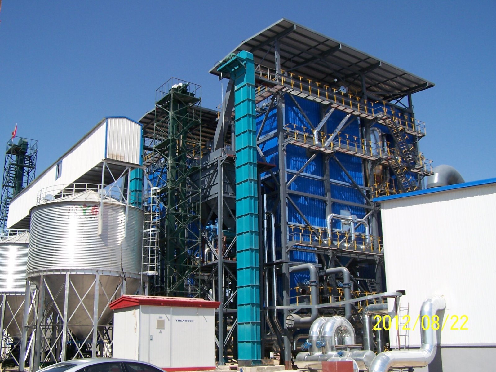
Cold, Warm, and Hot Commissioning Protocols: From First Fire to Full-Load Acceptance
Commissioning a biomass boiler is not a single event — it’s a staged process that unfolds over weeks, and skipping or compressing any phase tends to show up later as cracked refractory, leaking tube welds, or a performance test the boiler simply cannot pass. The three-phase structure exists for good engineering reasons, not bureaucratic ones.
Cold Commissioning: Verify Everything Before Any Heat
Cold commissioning happens before the first flame, and it deserves more time than most schedules allow. Every valve in the feed water, steam, blowdown, and drain circuits should be stroke-tested for full open/close travel and confirmed to match the P&ID position. This sounds obvious. In practice, a manually-locked isolation valve or a mistagged actuator signal shows up during cold checks on nearly every large project.
Interlock and trip function tests are non-negotiable hold points. Work through each shutdown logic path individually: high drum level trip, low-low water level trip (typically two independent level switches in a 2-of-3 voting arrangement), high furnace pressure, and induced-draft fan trip causing forced-draft fan runback. Simulate each input at the field transmitter level, not just by forcing signals at the DCS — you need to confirm the entire I/O loop, not just the logic card. Safety valve set-pressure should be confirmed against the stamped nameplate and the vessel pressure test certificate; do not assume factory settings survived shipping and rigging.
DCS/PLC loop checks at this stage should also validate combustion control responses — air-to-fuel ratio linkage, grate speed feedback, and O₂ trim signal from the flue-gas analyzer. A miscalibrated O₂ analyzer discovered during hot commissioning costs days, not hours.
Warm Commissioning and Refractory Dry-Out
The refractory dry-out curve is one of the most abused procedures in boiler commissioning. Castable and brick refractory contains chemically and physically bound moisture; drive it out too fast and you get steam-induced spalling that can compromise the furnace wall integrity for the life of the boiler.
Initial light-off should target roughly 10–15% of rated thermal load — enough to raise furnace temperature gently, not enough to shock the castable. Hold at 100–120 °C for 24–48 hours, depending on the total mass of refractory and ambient humidity. Wet seasons and high-humidity sites need the longer end of that range; I’ve seen dry-out on a coastal plant in a wet month require an extra 12 hours at the 100 °C hold simply because the castable had absorbed moisture from the air after installation. After the free moisture is out, step to a 200 °C hold (typically 8–12 hours), then 350 °C (another 8–12 hours), before approaching normal operating temperature. These aren’t arbitrary numbers — they correspond to phase transitions in binder chemistry and residual water release.
Operational warning: Do not rush the dry-out to recover schedule. Refractory repairs inside a furnace require a full cooldown, often 7–10 days of lost production, plus costly confined-space work. The dry-out curve is cheap insurance.
Hot Commissioning: Controlled Pressure Rise and First Blowdown
Once the refractory holds are complete and drum temperature is rising toward saturation conditions, steam pressure raise rate should be held to ≤ 0.05 MPa/min. Faster ramp rates create differential thermal stresses at drum nozzle welds and at the transition between heated and unheated tube sections. Monitor drum metal temperature spread — top-to-bottom differential above roughly 40–50 °C is a signal to slow the ramp, not push through it.
First blowdown is critical and often underestimated. Mill scale, weld spatter, and construction debris accumulate in headers and lower drums during erection. Conduct continuous bottom blowdown early in the pressure rise and take intermittent blowdowns from each header drain in sequence. Water sample clarity and conductivity should trend toward acceptable limits before steam is admitted to any downstream process or turbine.
Steam blowing of superheater outlet piping — using the boiler’s own steam at roughly 25–30% of design flow, with rapid pressure dump cycles — removes debris that boiler blowdowns cannot reach. Each blow cycle should be assessed using a polished target plate in a temporary spool; the acceptance criterion is typically no new impact marks after two consecutive blows. This procedure protects turbine blades and control valves from erosion damage that won’t show up until months into operation.
A steam pressure raise rate exceeding 0.1 MPa/min during initial hot commissioning will not damage a well-designed biomass boiler drumFalse
Drum and nozzle weld geometry creates thermal stress concentrations during rapid pressure rise. Most boiler manufacturers specify ≤ 0.05 MPa/min for initial heat-up; exceeding this risks fatigue crack initiation at weld toes, which may not be immediately visible but propagates under cyclic loading.
Full-Load Performance Acceptance Test
The 72-hour continuous run at 100% MCR is the formal proof of the project. Instrumentation should be calibrated and certified before the test window opens — a disputed fuel calorific value measurement or a drifting flow meter can invalidate the entire run and restart the clock.
Parameters to measure and record at regular intervals (typically every hour): steam output (kg/h), steam pressure and temperature at the superheater outlet, feed water flow and inlet temperature, fuel consumption rate and representative fuel sampling for proximate/ultimate analysis and calorific value determination, blowdown flow and frequency, and auxiliary power consumption for fans, pumps, and fuel handling. Net thermal efficiency is calculated against the guaranteed value agreed in the supply contract — typically 85–88% for a well-configured stoker-fired unit with economizer, higher for CFB configurations.
Emission compliance measurements — NOx, SO₂, and particulate matter — should be taken during the acceptance test under steady full-load conditions, not during a transient. Bag-house filter performance in particular degrades if tested during a grate load change; the test window needs at least 30 minutes of stable operation before sampling.
If the boiler falls short of the efficiency guarantee, the sequence matters: check fuel calorific value first (biomass fuel quality variation is the most common culprit), then excess air level, then heat loss from unburned carbon in ash. Chasing an efficiency shortfall without isolating the variable wastes time and generates conflict between the EPC contractor and the boiler supplier.
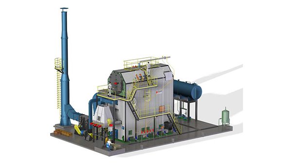
Emissions Compliance Tuning and Combustion Optimization After Light-Off
Most contractors hand over a biomass boiler once it hits rated steam output on a single fuel during the hot commissioning trial. That’s the wrong place to stop. What you have at that point is a mechanically sound boiler running on a set of combustion parameters that someone estimated from a similar project. Turning that into a permit-compliant, cost-efficient system takes another two to six weeks of disciplined optimization work — work that owners rarely budget for and regularly regret skipping.
Excess-Air Ratio and Primary/Secondary Air Split
The target lambda for a traveling-grate biomass unit sits in the range of 1.20–1.35, and for a CFB biomass boiler it’s tighter, typically 1.15–1.25. These aren’t arbitrary — every tenth of a lambda point you run above the optimum costs you in flue-gas heat loss, and every tenth below it shows up as unburned carbon in the bottom ash and elevated CO at the stack.
Loss-on-ignition in the grate ash is your fastest field indicator. A target of under 3% LOI is achievable with most wood chip and agricultural residue fuels once the primary/secondary air split is properly calibrated. In practice, primary air controls grate-layer combustion and sets the bed temperature; secondary air — injected at the furnace arch or over-fire ports — burns out CO and fine char carried up from the grate. Getting this split wrong is the single most common cause of high LOI and CO exceedances on stoker-fired units. A 10–15% shift in the primary-to-secondary ratio can move CO from 300 mg/Nm³ down below 80 mg/Nm³ on the same fuel, depending on moisture content and bed depth.
Run a formal air-ratio survey at 60%, 80%, and 100% MCR, logging O₂ at the furnace exit, CO at the economizer outlet, and ash LOI from each test run. Update the combustion control curves before touching anything else.
SNCR Tuning and Ammonia Slip Management
If the unit has a selective non-catalytic reduction system for NOx control — which most new biomass boilers above roughly 20 t/h now do, either to meet EU IED limits or increasingly strict regional standards — the urea injection window is critical. Urea reacts effectively with NOx in the 850–1050 °C flue-gas temperature band. Below that window, urea decomposes incompletely and you get ammonia slip. Above it, thermal decomposition bypasses the NOx reaction entirely.
Ammonia slip above 5 ppm at the stack indicates either an excessively high normalized stoichiometric ratio (NSR) or incorrect injection location relative to the temperature field.True
Ammonia slip is a well-documented consequence of SNCR over-injection or poor temperature-zone targeting; 5 ppm is a common regulatory and operational threshold cited in EU BAT reference documents and standard SNCR design practice.
Target NSR between 1.0 and 1.5. Starting at 1.0 and stepping up while monitoring both stack NOx and ammonia slip is the right sequence. Don’t assume the design NSR from the equipment supplier is correct for your actual fuel — biomass NOx generation varies considerably with nitrogen content in the fuel, and rice husk behaves nothing like pine chip in this regard.
Bag-House Pressure Drop and Leak Detection
The bag-house filter pressure drop should settle in the 1.0–1.5 kPa range under normal operating conditions. If you’re seeing it climb toward 2.0 kPa and the cleaning cycle can’t pull it back, you’re either running the cleaning pulse frequency too low, dealing with moisture-blinded bags from a cold start, or using a bag material that isn’t compatible with the ash chemistry. Phenolic-impregnated bags in high-alkali rice straw applications, for example, can blind within months.
Cross-reference bag condition against your CEMS opacity readings. A sudden opacity spike that doesn’t correlate with a load change is almost always a bag failure, not a combustion event. Establish that correlation baseline during the optimization phase, not after a permit exceedance.
Fuel Flexibility and Combustion Curve Updates
Document load trials on every contracted fuel type — don’t leave this to the operations team to figure out after handover. A 20% swing in biomass moisture content, which is normal between dry-season and wet-season deliveries in most tropical and subtropical sourcing regions, shifts the required air volume, grate speed, and fuel feed rate enough to push CO or LOI out of spec if the control curves haven’t been updated.
Run each fuel trial at minimum two load points, log the combustion parameters that produce compliant emissions and acceptable ash LOI, and lock those as named fuel presets in the DCS. The goal is stable, unattended fuel-blend transitions — operators shouldn’t need to manually intervene every time the fuel yard shifts from eucalyptus chip to palm kernel shell. That level of automation only happens if the optimization work is done properly and the curves are actually written into the control system before commissioning sign-off.
Handover Documentation, Operator Training, and Warranty Commissioning Records
The boiler runs. The acceptance test is signed. Everyone wants to leave site. This is exactly the moment when projects cut corners that cost the plant owner dearly six months later — a warranty dispute with no weld records to reference, an operator who never practiced a manual trip, or a bag-filter blowback failure because nobody ordered replacement bags before the first scheduled maintenance window.
Getting handover right is not bureaucratic box-ticking. It is the legal and operational foundation the plant will stand on for the next fifteen to twenty years.
The Mandatory Document Package
Every biomass boiler project should close out with a bound, indexed handover dossier — physical copies plus a controlled digital set. In practice, what that means:
As-built P&IDs are non-negotiable. Not the issued-for-construction revision, the as-built revision reflecting every field change, relocated drain valve, or re-routed instrument impulse line. Surprisingly often these diverge from IFC drawings by more than people expect, especially on fuel-handling conveyors and ash-handling ductwork that got modified during erection.
The package should include full hydrostatic test certificates for pressure parts, covering drum, headers, superheater, economizer, and any interconnecting pipework — with test pressures, hold durations, and inspector signatures. Alongside these: weld inspection records (RT or UT film reports or digital image archives), NDT summary sheets, and PWHT charts where applicable. These documents are what a future insurance surveyor or boiler authority inspector will ask for first.
Third-party inspection (TPI) reports — from the notified body, classification society, or local boiler authority — need to be originals or certified copies, not contractor-printed scans. Critically, the boiler registration certificate from the local statutory authority must be in the owner’s hands before commercial operation. Running an unregistered pressure vessel is a regulatory violation that can shut the plant down on short notice, regardless of how well it actually operates.
Equipment data sheets, O&M manuals, and vendor documentation for every major item — ID/FD fans, grate drive gearboxes, feed-water pumps, instrumentation transmitters — should be compiled in a separate vendor data register. OEM part numbers for wear items need to be explicitly listed, not buried in appendices.
Operator Training: What Actually Needs to Happen
A two-day classroom session followed by a signed attendance sheet is not operator training. For a 20–75 t/h biomass steam boiler, a realistic program runs three to five days minimum, structured roughly as follows.
Classroom sessions should cover boiler water chemistry — the relationship between conductivity, TDS limits, and blowdown frequency — and basic thermodynamic principles relevant to reading steam tables and understanding superheat margins. Operators who understand why a procedure exists follow it more reliably than those who just memorize steps.
Desktop walk-throughs of normal start-up and shutdown sequences, using the actual HMI screenshots or a mimic panel if available, let operators build procedural memory before touching live equipment. Simulator-based training is rarely available for industrial biomass units at this scale, so the desktop walk-through carries more weight than on large utility projects.
The hands-on emergency drill is the piece most commissioning teams skip when they’re under schedule pressure. It needs to include at minimum: manual boiler trip from the local panel, manual feedwater pump changeover, manual blowdown procedure, and fuel-feed emergency stop. Each operator — not just the lead shift — should complete this individually and have it recorded.
The 72-Hour Acceptance Test Report
The commissioning performance test report is the document that defines whether the EPC contractor has met its contractual obligations. It should be tabulated cleanly: guaranteed values versus measured values at each load point tested (typically 75%, 100%, and sometimes 110% MCR), with measurement uncertainty stated.
Parameters that typically require formal deviation analysis if they fall outside specification include thermal efficiency, steam output at rated pressure and temperature, flue-gas emissions (NOx, SO₂, particulate matter against the applicable standard — EU IED or GB 13271 depending on jurisdiction), and auxiliary power consumption. Any deviation should have a root-cause note and an agreed corrective action with a resolution date. A report that simply shows all values green without a deviation log looks suspicious, honestly — some parameter nearly always needs a minor correction.
A 72-hour continuous acceptance run is sufficient to validate steady-state boiler performance and emission compliance for most industrial biomass units in the 10–75 t/h range.True
Most industrial boiler procurement contracts and standards (including common EPC practice under ASME PTC 4 and EN 12952 frameworks) specify 72-hour or similar continuous test durations for acceptance at rated load. This is adequate for steady-state thermal and emissions verification, though it does not capture seasonal fuel variability or long-term fouling trends.
Spare-Parts Handover for the First Operating Period
The recommended spares list for the first 12–24 months should be handed over physically with the equipment, not just listed in a document. Critical items for a biomass stoker boiler typically include: grate bars and grate bar pins (consumption rate depends heavily on ash abrasiveness and fuel alkalinity — rice husk ash is far more aggressive than wood chip ash), FD/ID fan impeller wear plates or complete impeller sets if the fuel carries significant abrasive fines, bag-filter filter bags with a full set of replacements (bag life on biomass units running rice straw or demolition wood can be as short as 18 months), and instrumentation transmitters for pressure, temperature, and flow — the specific models that match the installed instruments, not generic alternatives.
Re-order lead times should be documented next to each line item. For imported components — say, a German-made valve actuator or a Japanese gearbox — lead times of 16–24 weeks are realistic. If the plant is operating in Southeast Asia or West Africa and the OEM has no regional distributor, that number can stretch further. An operator who discovers this after a failure, rather than before, faces an extended outage.
The spare-parts list is also where the handover process protects the EPC contractor: a signed acknowledgment that the owner received the recommended spares package, and chose to accept or decline specific items, creates a clear record if a warranty dispute arises later from a failure that could have been prevented with an available spare.
Frequently Asked Questions About Biomass Boiler Installation and Commissioning
How long does commissioning take for a 20 t/h biomass steam boiler?
Realistically, budget 10–14 weeks from the day the site is actually ready — not the day the equipment arrives. The two most common schedule-killers are refractory dry-out and CEMS certification lag. Refractory dry-out alone on a 20 t/h unit typically runs 7–12 days of controlled low-fire operation following a strict temperature curve; rush it to save a week and you get spalling in the furnace walls within the first month of production. Beyond that, third-party inspection hold points — hydrostatic test witness, safety valve set-pressure verification, pressure-part NDE sign-off — depend entirely on how quickly the notified body or local authority inspector can be scheduled. In Southeast Asia and the Middle East that scheduling gap can add 2–4 weeks on its own. Fuel availability is underrated: if the biomass supply chain isn’t contracted and stockpiled before cold commissioning begins, you will sit idle waiting for enough consistent-quality fuel to run meaningful load trials. CEMS (continuous emissions monitoring system) certification is often the last gate, and in EU-regulated markets the calibration and certification process alone can take 3–6 weeks after the analyzer is installed.
Can a biomass boiler be retrofitted to burn wood chips and rice husk simultaneously?
Yes, but it requires more than just mixing the fuels in the hopper. Rice husk has a bulk density roughly 40–50% lower than wood chips and an ash content that can run 15–20% by weight versus 1–3% for clean wood chips. On a traveling-grate boiler, multi-fuel firing typically needs separate metering screws or variable-speed belt feeders for each fuel stream, a revised grate speed control strategy, and — critically — upgraded bottom-ash and fly-ash extraction capacity. The high silica ash from rice husk also raises the risk of clinker formation and grate bar fouling if the furnace temperature profile isn’t retuned. CFB boilers handle multi-fuel blends more gracefully because the fluidized bed smooths out fuel variability, but you still need to check the cyclone and return-leg sizing against the combined ash load. Don’t skip a combustion simulation or at minimum a heat-and-mass balance review before committing to a fuel blend; the capital cost of the retrofit is modest, but an undersized ash system will cost you in downtime.
What is the minimum feed water quality specification?
For industrial biomass steam boilers operating at 1.0–2.5 MPa, total hardness should be below 0.03 mmol/L (roughly 3 µmol/L as CaCO₃ equivalent at the boiler inlet), conductivity below 150–300 µS/cm depending on operating pressure, dissolved oxygen below 0.05 mg/L, and pH held between 8.5 and 9.5. Exceed hardness limits in the first weeks and you will start building scale on the waterwall tubes faster than most operators expect — scale as thin as 0.5 mm raises tube metal temperature by 30–50 °C depending on heat flux, which accelerates creep and can cause tube failure within one to two operating seasons.
Scale buildup of 1 mm on boiler tube internal surfaces can increase fuel consumption by approximately 2–3% due to reduced heat transfer efficiency.True
This aligns with established heat transfer engineering principles; the exact figure depends on scale composition and operating heat flux, but the 2–3% range is consistent with published boiler efficiency data and field measurements.
Soft water or RO pre-treatment is not optional on any serious installation. Conductivity spikes during early operation often trace back to inadequate flushing of pipe installations before filling — a simple pre-commissioning procedure that gets skipped more often than it should.
How does commissioning differ between a traveling-grate and a CFB biomass boiler?
The difference is significant. On a traveling-grate unit, the critical early-operation focus is grate speed calibration against fuel bed depth and bed temperature uniformity — get this wrong and you get either fuel pile-up at the rear seal or excessive unburned carbon dropping into the ash pit. The refractory dry-out curve is relatively straightforward because the furnace geometry is simpler.
A CFB biomass boiler introduces bed material management from day one. Initial cold commissioning involves filling the bed with sized silica sand or limestone, verifying fluidization velocity at minimum airflow before any fuel is introduced, and checking cyclone inlet velocity and pressure drop against design. The hot commissioning ramp is slower — typically 5–8 days to reach stable bed temperature and circulating load — because the external heat exchanger (if fitted) and the cyclone return leg need to reach thermal equilibrium before you can push load. Tube erosion at the cyclone inlet and return duct is a known early-operation risk on CFB units; inspect these zones at the first scheduled short outage, usually around 500–1,000 operating hours.
What certifications and inspection hold points apply for export projects?
For Southeast Asia: most markets accept PED-equivalent documentation or ASME certification on pressure parts, but local authority sign-off (e.g., DOSH in Malaysia, BPOM or Disnaker in Indonesia) is still required before operation. The Middle East generally follows ASME Section I for steam boilers, with third-party inspection by a body acceptable to the local municipality or Aramco/ADNOC vendor qualification system if applicable. Europe requires CE marking under the Pressure Equipment Directive (PED 2014/68/EU), notified body involvement at design and manufacturing stage, and emissions compliance demonstrated against EU IED limits — NOx below 200 mg/Nm³, particulate matter below 20 mg/Nm³ with a bag-house filter, SO₂ below 50 mg/Nm³. Starting the notified body engagement after equipment fabrication is a frequent and expensive mistake.
What causes high unburned carbon in bottom ash during early operation?
Usually one of three things: grate speed set too fast (fuel residence time too short), primary air distribution uneven across the grate width, or fuel moisture significantly higher than the design basis. In the first weeks, operators tend to increase grate speed reactively when they see bed temperature rising, which actually makes unburned carbon worse. The correction is to slow the grate, increase secondary air slightly, and verify that the fuel being delivered actually matches the design moisture spec — in practice, freshly delivered agricultural residues can run 5–10 percentage points wetter than the contracted specification, especially in humid seasons. Unburned carbon loss of more than 3–5% in bottom ash is a signal worth investigating promptly; on a 20 t/h unit burning biomass at roughly 18–20 GJ/t, that translates to a meaningful daily fuel cost penalty.
References
- BPVC Section I — Rules for Construction of Power Boilers — ASME
- BPVC Section VII — Recommended Guidelines for the Care of Power Boilers — ASME
- National Board Inspection Code — 2025 Edition Changes and Installation Requirements — National Board of Boiler and Pressure Vessel Inspectors
- Annual Reminder for Restart of Boilers — Startup Safety Checklist — National Board of Boiler and Pressure Vessel Inspectors
- NFPA 85 — Boiler and Combustion Systems Hazards Code — National Fire Protection Association
- Valmet BFB Boiler — Bubbling Fluidized Bed Biomass Boiler Technology — Valmet
- PowerFluid Circulating Fluidized Bed Boilers for Biomass and Alternative Fuels — ANDRITZ
- Water for the Boiler — Boiler Water Treatment and Steam System Reliability — Spirax Sarco
- Biomass Combustion and Cofiring — Technical Information — IEA Bioenergy Task 32
- PTC 4 — Fired Steam Generators: Performance Testing — ASME