Non-destructive testing (NDT) helps assess the condition of industrial oil and gas fired boiler tubes, drums, shells, and other pressure-retaining components without unnecessarily damaging the equipment. Effective inspection involves more than selecting an ultrasonic or radiographic testing method. It requires identifying vulnerable components, understanding potential damage mechanisms, and matching examination techniques to specific inspection objectives.
Inspection priorities differ between fire-tube and water-tube boilers. Fire-tube designs require particular attention to shells, furnaces, tubesheets, and tube connections, while water-tube boilers involve generating tubes, headers, drums where fitted, and associated pressure welds.
Common examination methods include visual testing (VT), ultrasonic testing (UT), magnetic particle testing (MT), liquid penetrant testing (PT), and radiographic testing (RT). Each has different capabilities and limitations.
This guide explains where to inspect, how to select appropriate NDT methods, and how findings should inform engineering assessments and maintenance decisions.
1. What Pressure Parts Need NDT Inspection in Oil & Gas Fired Boilers?
Before selecting an examination method, inspectors must establish the boiler’s pressure boundary and identify components requiring examination based on design, operating conditions, and inspection history.
Pressure Parts in Fire-Tube Boilers
In fire-tube boilers, combustion gases travel through the furnace and smoke tubes, transferring heat to water contained within the surrounding pressure shell.
Key inspection locations include:
- Boiler shell: Pressure-retaining surfaces potentially affected by corrosion, wall thinning, or weld discontinuities.
- Furnace and furnace connections: Areas where abnormal overheating, thermal stress, or deformation may occur.
- Smoke tubes: Tube walls and ends susceptible to corrosion or localized deterioration.
- Tubesheets and tube-to-tubesheet joints: Connections where leakage or cracking may require further investigation.
- Nozzles and pressure welds: Locations requiring examination according to geometry, stress conditions, and operating history.
Pressure Parts in Water-Tube Boilers
In water-tube boilers, water or steam-water mixtures flow through tubes exposed to combustion heat.
Relevant pressure parts may include steam drums, waterwall and generating tubes, headers, nozzles, and associated welds. Superheater and economizer tubes should also be considered where these components are fitted.
These structural differences affect both inspection access and method selection.
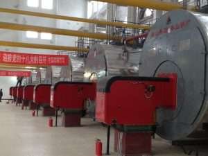
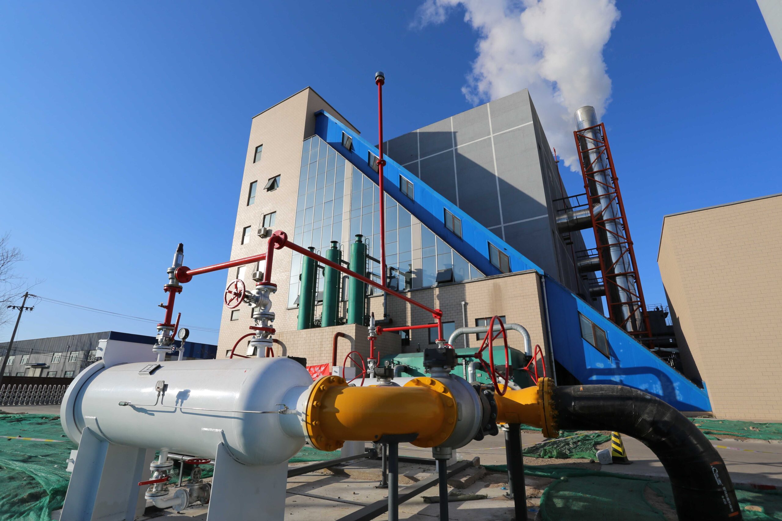
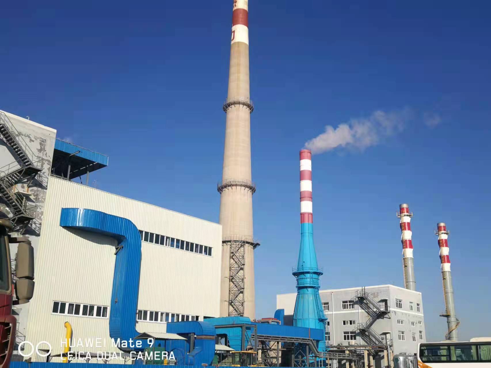
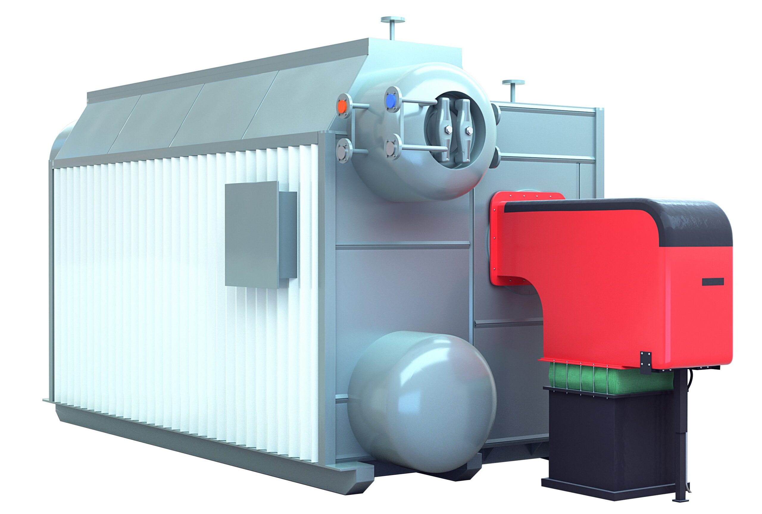
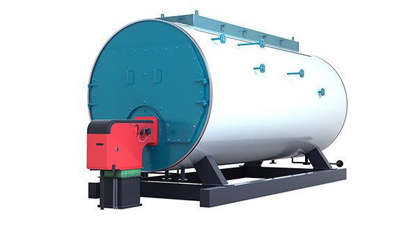
For example, Taishan Group’s industrial oil and gas fired boiler range includes WNS and SZS series. Their different configurations illustrate why one inspection checklist cannot automatically be applied to every industrial oil or gas fired boiler.
2. What Damage Mechanisms Determine NDT Inspection Priorities?
An effective inspection plan begins with identifying credible damage mechanisms rather than examining every component using the same procedure.
Operating temperature, pressure, water chemistry, fuel composition, thermal cycling, and previous inspection findings all influence the areas requiring attention.
| Damage mechanism | Potentially affected components | Inspection priority |
|---|---|---|
| Waterside corrosion and pitting | Shells, drums, tubes, headers | Localized metal loss and remaining wall thickness |
| Thermal fatigue | Nozzle connections, tube connections, welded joints | Cracking at susceptible locations |
| Overheating-related deterioration | Furnace pressure parts, generating tubes, superheaters | Deformation, cracking, and material deterioration |
| Flue-gas-side corrosion | Gas-exposed heat-transfer surfaces | Localized corrosion and wall thinning |
| Weld-related discontinuities | Pressure-retaining welds | Relevant surface or internal indications |
How Operating Conditions Affect Inspection Priorities
Frequent startups, shutdowns, or rapid load changes can produce repeated thermal expansion and contraction. Where component geometry or restraint creates stress concentrations, this may increase concern about fatigue-related cracking.
Water-treatment problems, dissolved oxygen, and deposits may contribute to waterside corrosion or localized overheating. Inspection plans should therefore consider water chemistry records and previous tube failures.
Fuel properties can also influence corrosion risks. For example, sulfur-containing liquid fuels may increase the possibility of acid-related corrosion when flue-gas-side surfaces operate below the relevant acid dew point.
These conditions help identify inspection priorities but do not establish that damage exists. NDT is used to investigate suspected deterioration and characterize detectable indications.
3. How to Inspect Fire-Tube Boiler Pressure Parts Using NDT Methods?
Fire-tube boiler inspections should concentrate on the pressure shell, furnace, smoke tubes, tubesheets, and associated connections. The examination approach depends on the suspected damage, component geometry, material, and available access.
Inspecting Boiler Shells and Furnace Pressure Parts
Visual examination provides the starting point for identifying abnormal conditions.
Inspectors should look for visible deformation, leakage evidence, corrosion, unusual deposits, and other changes that may indicate deterioration.
Areas with previous corrosion findings, recurring leakage, or unfavorable water-side conditions may warrant closer examination rather than relying solely on evenly distributed measurement points.
Ultrasonic thickness testing (UT thickness gauging) can measure remaining wall thickness at selected accessible locations. However, individual readings may miss localized pitting between measurement points.
Where corrosion is uneven or concentrated, an expanded measurement grid or suitable ultrasonic scanning technique may provide a more representative assessment.
Furnace pressure parts require particular attention when deformation, scale accumulation, or operating records suggest abnormal heat exposure.
Visual examination can identify some geometric changes, while ultrasonic measurements can assess accessible wall thickness. Neither method alone establishes the extent of possible metallurgical deterioration caused by overheating.
Suspected overheating may require additional investigation, including appropriate material assessment, depending on the circumstances.
Where cracking is suspected around suitable welded connections, MT can detect surface and certain near-surface discontinuities in ferromagnetic materials. PT detects discontinuities open to the examined surface on suitable nonporous materials.
Method selection must account for material properties, surface preparation, and accessibility.
Inspecting Smoke Tubes and Tube-to-Tubesheet Joints
Smoke tubes and their connections deserve targeted examination because deterioration may be concentrated near tube ends or other locally affected surfaces.
Inspection should begin by checking accessible areas for leakage evidence, corrosion, deposits, and visible connection damage.
If leakage is observed around a tube end, inspectors should not automatically attribute it to tube-wall corrosion. The cause may involve the tube wall, the tubesheet, or the integrity of an expanded or welded connection.
The inspection objective should therefore distinguish between:
- Tube-wall deterioration: Loss of metal thickness or localized damage within the tube.
- Connection deterioration: Cracking or other defects affecting the tube-to-tubesheet joint.
- Leakage without an immediately visible defect: Conditions requiring further investigation before a repair decision.
Depending on tube material, diameter, geometry, and access, appropriate ultrasonic or specialized electromagnetic examination techniques may be considered.
However, conventional UT thickness gauging is not equivalent to ultrasonic flaw detection, and neither should be assumed to provide complete coverage of a tube-to-tubesheet connection.
MT or PT may be useful for accessible connection surfaces where the suspected discontinuity and material are suitable for the selected method.
Inspecting Tubesheets and Pressure-Retaining Welds
Tubesheets and pressure-retaining welds should be examined according to their geometry, service exposure, and relevant inspection history.
For example, a nozzle connection with a history of thermal cycling may justify targeted crack examination, while a shell weld with a suspected internal discontinuity may require an appropriate volumetric examination technique.
MT or PT can address suitable surface-related inspection objectives.
Conventional ultrasonic flaw detection, phased array ultrasonic testing (PAUT), or RT may be appropriate for certain weld examinations, provided the applicable procedure and geometry support reliable detection.
PAUT is not automatically appropriate for every weld. Complex joint geometry, limited scanning access, unsuitable material properties, or unfavorable flaw orientation can restrict its effectiveness.
| Pressure part | Main inspection objective | Potential examination method | Important limitation |
|---|---|---|---|
| Boiler shell | Assess wall loss and relevant weld conditions | VT, UT, qualified weld examination | Local thickness readings may miss isolated deterioration |
| Furnace pressure parts | Investigate distortion, thinning, or suspected cracking | VT, UT, MT/PT where suitable | Overheating damage may require further material assessment |
| Smoke tubes | Examine suspected corrosion or wall thinning | VT, qualified tube examination methods | Small diameter and access may limit coverage |
| Tube-to-tubesheet joints | Investigate leakage or accessible cracking | VT, MT/PT where suitable | Internal joint condition may remain uncertain |
| Pressure-retaining welds | Characterize relevant surface or internal indications | MT/PT, UT/PAUT, RT as applicable | Capability depends on weld geometry and the selected technique |
The most reliable approach is to select the method based on the inspection question, rather than applying every available NDT technique to every component.
4. How to Inspect Water-Tube Boiler Drums, Tubes, and Headers?
Water-tube boilers have different inspection priorities because their pressure boundaries include tube circuits, headers, and potentially drums operating under varying thermal and circulation conditions.
Inspection planning should account for the boiler’s actual configuration, particularly when the equipment experiences frequent load changes or prolonged high-temperature operation.
Inspecting Steam Drums and Drum Connections
Where a steam drum is installed, inspection should examine accessible internal and external surfaces for corrosion, pitting, deposits, and visible abnormalities.
Particular attention may be needed at nozzle connections, relevant welds, and locations identified through previous examination findings.
For example, localized pitting near a drum connection may require a denser thickness measurement pattern than a general shell survey. The objective is to determine the extent and distribution of metal loss, not simply record one remaining-thickness value.
UT thickness gauging can assess accessible wall thickness, while appropriate ultrasonic flaw detection techniques may be considered for certain internal discontinuities.
MT or PT can be used for suitable surface-related examinations.
The condition of a drum cannot be established from isolated thickness readings alone. Inspectors must also consider examination coverage, material condition, geometry, and the significance of any detected indications.
Inspecting Waterwall, Generating, and Heat-Transfer Tubes
Waterwall and generating tubes should be examined for credible deterioration mechanisms associated with their operating conditions.
Where water chemistry records indicate deposits or corrosion problems, inspection may prioritize tube areas susceptible to localized wall loss or overheating.
Where operating records show abnormal temperature exposure, visual examination may identify deformation or other changes requiring further investigation.
UT thickness gauging can provide useful measurements at accessible locations. However, tube curvature, small diameter, surface condition, and probe configuration can affect measurement accuracy.
A limited number of readings may not adequately characterize localized pitting. If initial findings suggest nonuniform deterioration, inspectors may need additional measurement locations or a qualified scanning technique.
Superheater tubes, where fitted, may require consideration of temperature-related damage mechanisms in addition to corrosion.
For economizer tubes, inspection planning may emphasize water-side or flue-gas-side corrosion according to operating history and actual exposure conditions.
Oil and gas firing does not eliminate waterside deterioration risks. Water chemistry, deposits, and circulation conditions remain relevant regardless of the fuel used.
At the same time, inspection priorities should not simply reproduce the ash erosion patterns associated with coal-fired or circulating fluidized bed boilers unless similar mechanisms are supported by the equipment’s actual operating conditions.
Inspecting Headers, Nozzles, and Pressure Welds
Headers and nozzle connections may experience localized stresses associated with thermal expansion, component restraint, and operating cycles.
Inspection locations should be selected with reference to design geometry, service conditions, previous repairs, and historical findings.
For example, a connection experiencing repeated thermal cycling may warrant targeted surface-crack examination, while a region with suspected corrosion may be better assessed initially through thickness measurements.
MT is suitable for applicable ferromagnetic components when surface or near-surface discontinuities are of concern. PT can be selected for appropriate surface-breaking discontinuities.
Qualified ultrasonic flaw detection or PAUT may be considered for suitable weld configurations, but examination effectiveness depends on scanning access, weld geometry, material properties, and expected flaw orientation.
These factors should be established before choosing a technique, rather than assuming advanced ultrasonic equipment will overcome all access or geometry limitations.
| Pressure part | Principal concern | Inspection consideration |
|---|---|---|
| Steam drum | Pitting, corrosion, weld-related indications | Combine visual findings with targeted thickness or flaw examination |
| Waterwall and generating tubes | Local wall loss or overheating-related damage | Select measurement coverage according to suspected deterioration |
| Superheater and economizer tubes | Temperature-related deterioration or corrosion | Consider component-specific operating conditions |
| Headers and nozzle welds | Suspected cracking or localized corrosion | Match surface or volumetric examination to the expected defect |
The resulting inspection program should address the components presenting credible risks rather than relying on an identical examination pattern for every water-tube boiler.
5. How Should NDT Results Be Evaluated and Documented?
NDT provides evidence about examined components, but the findings must be interpreted before decisions are made about repair, replacement, or continued operation.
Understanding NDT Findings and Their Limitations
An ultrasonic thickness reading represents the measured thickness at a particular location under the conditions of the examination. It does not independently establish the structural adequacy of the entire component.
The significance of wall loss depends on the applicable minimum required thickness, component geometry, operating conditions, extent of damage, and governing requirements.
Similarly, an NDT indication does not automatically represent an unacceptable defect.
Indications may require additional examination, characterization, or engineering assessment before their significance can be established.
Different methods also detect different types of discontinuities. As explained in the ASNT guide to ultrasonic testing, ultrasonic examination includes different techniques with distinct capabilities and applications.
Therefore, inspectors should distinguish between:
- Thickness gauging used to assess wall loss.
- Ultrasonic flaw detection used to investigate relevant internal or planar discontinuities.
- Surface examination techniques used to identify applicable surface or near-surface indications.
- Areas that were not examined or could not be reliably assessed.
A satisfactory result does not prove that all unexamined areas are free from damage.
Recording Findings and Determining Follow-Up Actions
An NDT report should identify the examined component, inspection location, examination method, relevant coverage, and recorded findings.
Supporting information normally includes the examination procedure, equipment details, personnel qualifications, calibration information where applicable, and any limitations affecting interpretation.
Results should be compared with previous inspection records where available.
Where deterioration is detected, possible follow-up actions include:
- Additional examination to determine the extent of damage.
- Engineering assessment against applicable requirements.
- Monitoring under an approved inspection program.
- Authorized repair or component replacement.
- Continued service only where the required assessment and authorization support that decision.
The ASME Boiler and Pressure Vessel Code Section V provides nondestructive examination requirements when referenced by applicable codes or other governing documents.
However, Section V should not be treated as a universal standalone acceptance standard for every in-service boiler defect. The applicable construction code, jurisdictional requirements, inspection rules, and engineering assessment framework must also be considered.
Preparing for an In-Service NDT Inspection
Before examination, the boiler must be placed in a condition suitable for the planned work. This may require shutdown, isolation, depressurization, cooling, and controlled access.
Internal inspection may also require confined-space entry procedures, atmosphere testing, and site-specific permits.
Inspectors should review available design drawings, material information, operating records, previous NDT reports, and repair history.
Examination should be performed by appropriately qualified personnel, with authorized inspectors involved where required by applicable rules.

6. Frequently Asked Questions
Can ultrasonic testing detect every defect in boiler tubes?
No. Ultrasonic thickness gauging and ultrasonic flaw detection serve different purposes. Their effectiveness depends on the equipment, examination procedure, material, tube geometry, and defect characteristics. Isolated thickness readings may miss localized pitting, while certain crack orientations or inaccessible areas may limit flaw detection. Additional techniques or examination coverage may be necessary.
Is radiographic testing always necessary for boiler weld inspection?
No. The required examination method depends on the applicable code, weld design, material, and inspection objective. RT may be appropriate for certain weld examinations, while qualified UT, PAUT, MT, or PT may be suitable in other circumstances. Any alternative to a required method must be permitted by the governing requirements.
How often should industrial oil and gas fired boilers undergo NDT inspection?
There is no universal NDT interval for every oil or gas fired boiler. Examination frequency and scope depend on jurisdictional requirements, equipment condition, operating history, previous inspection results, and the applicable inspection program. A periodic boiler inspection does not necessarily require every pressure component to undergo the same NDT methods.
Does a detected crack or reduced tube wall thickness always require replacement?
Not automatically. A detected indication must be confirmed and evaluated according to its characteristics, component condition, and applicable requirements. Depending on the findings, further examination, authorized repair, replacement, or another approved engineering disposition may be necessary. Suspected critical defects must be resolved before continued operation is authorized.
Conclusion
Effective NDT inspection of industrial oil and gas fired boilers depends on selecting examination methods that match the component, its geometry, operating history, and suspected damage mechanism.
Fire-tube boilers require focused assessment of shells, furnaces, smoke tubes, and tubesheet connections. Water-tube boilers demand different inspection priorities across drums, tubes, headers, and pressure-retaining welds.
Qualified examination and engineering evaluation are essential for interpreting results and determining appropriate follow-up actions.
Boiler owners should retain relevant design drawings, material documentation, and inspection records to support future assessments. Taishan Group’s quality control and manufacturing information provides additional background on its manufacturing quality management and inspection capabilities.
References
American Society for Nondestructive Testing (ASNT) — Ultrasonic Testing (UT)
American Society for Nondestructive Testing (ASNT) — Magnetic Particle Testing (MT)
American Society for Nondestructive Testing (ASNT) — Liquid Penetrant Testing (PT)
American Society of Mechanical Engineers (ASME) — BPVC Section V: Nondestructive Examination