Industry News

How Fuel Types & Combustion Influence Industrial Coal-Fired Boiler Selection

How Fuel Types & Combustion Influence Industrial Coal-Fired Boiler Selection

When selecting an industrial coal-fired boiler, many buyers focus on capacity or pressure—but overlooking the impact of coal type and combustion behavior can lead to inefficient combustion, excessive emissions, and frequent maintenance issues. Different types of coal have vastly different properties that directly affect boiler design, combustion performance, fuel handling, and emission control systems. A properly matched fuel-boiler combination ensures maximum efficiency, equipment longevity, and regulatory compliance.

Fuel types and combustion characteristics affect your choice of industrial coal-fired boiler by determining furnace dimensions, combustion air supply, ash removal design, slagging tendency, and flue gas treatment systems. Coal varies in moisture, ash content, calorific value, sulfur levels, and volatile matter, all of which influence how the fuel burns and what kind of boiler technology is best suited. Choosing the wrong configuration for your coal type can lead to poor efficiency, corrosion, excessive slag formation, and failure to meet environmental standards.

Let’s explore how to make the right decision based on the specific fuel characteristics relevant to your facility.

What Are the Main Types of Coal Used in Industrial Coal-Fired Boilers?

In industrial steam and power generation, coal-fired boilers remain vital for applications demanding high pressure and continuous energy output. However, not all coal types perform the same in combustion systems. Choosing the wrong coal type for a specific boiler design can result in low combustion efficiency, excessive slagging, high emissions, and unplanned shutdowns. Industrial boilers must be tailored to the chemical and physical characteristics of the coal used, including calorific value, moisture content, ash composition, and volatile matter. Knowing the differences between the main types of coal used in boilers is essential for achieving stable combustion, regulatory compliance, and long-term operational reliability.

The main types of coal used in industrial coal-fired boilers are anthracite, bituminous coal, sub-bituminous coal, and lignite. Each type differs in carbon content, calorific value, moisture, and volatile matter, which influence combustion efficiency, slagging behavior, and emissions. Bituminous coal is the most commonly used due to its balance of high energy content and good combustion characteristics. Lignite, with high moisture and low energy density, requires specially designed boilers, while anthracite burns cleanly but needs high ignition temperatures.

Selecting the right coal type is critical to optimizing fuel cost, system longevity, and combustion performance. Let’s explore each one in detail with comparative data and practical implications for boiler operation.

All coal types can be used interchangeably in the same industrial boiler system.False

Different coal types have varying combustion characteristics, and most industrial boilers are designed for specific coal grades. Using incompatible coal types can lead to inefficient combustion, equipment damage, and high emissions.

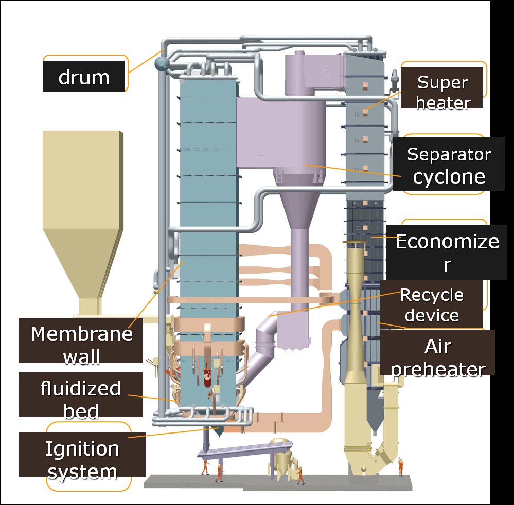
Classification of Coal Types by Combustion Characteristics

Coal types are typically classified based on rank, which reflects the degree of carbon concentration due to geological pressure and heat. Higher-rank coals have more carbon and energy, while lower-rank coals retain more moisture and volatile compounds.

Coal TypeCarbon (%)Moisture (%)Volatile Matter (%)Calorific Value (MJ/kg)Common Usage in Boilers
Anthracite86–973–82–828–33Rare, specialized high-temp boilers
Bituminous65–852–1512–4024–35Widely used in steam power & industry
Sub-bituminous45–6515–3015–3017–25Suitable for circulating fluidized bed
Lignite (Brown Coal)25–4530–6025–409–18Needs special low-temp boiler designs

Key Types of Coal for Boiler Systems

H3: Bituminous Coal – The Industrial Workhorse

Bituminous coal is the most widely used in industrial coal-fired boilers due to its balance of:

  • High calorific value (24–35 MJ/kg)

  • Moderate moisture and volatile matter

  • Reliable ignition and stable combustion

  • Adaptability to grate, pulverized, and fluidized bed systems

AdvantageImplication for Boiler Design
High energy contentSmaller boiler size per kW output
Moderate ash and sulfur contentRequires flue gas desulfurization (FGD)
Suitable for a wide load rangeStable steam supply, good turndown ratio

H3: Sub-Bituminous Coal – Lower Grade, But Reliable

Sub-bituminous coal has:

  • Moderate energy content (17–25 MJ/kg)

  • Higher moisture and volatile matter than bituminous

  • Lower sulfur content (environmental benefit)

Best used in:

  • Circulating Fluidized Bed (CFB) boilers

  • Plants focused on lower emissions or cheaper fuel availability

ProsCons
Lower SO₂ emissionsLarger combustion chamber required
Good flame propagationHigher flue gas volume, more particulate
Cost-effective in some marketsMore ash and moisture to manage

H3: Lignite – Economical But Technically Demanding

Also called brown coal, lignite has:

  • Very low energy density (9–18 MJ/kg)

  • High moisture (often 30–50%)

  • High volatile matter → easy ignition, unstable flame

Used in:

  • Locally mined, low-cost power plants

  • Special boilers with pre-drying stages or large furnaces

ChallengesMitigation Strategy
High moistureIntegrate fuel dryers or larger grate
High ash formationUse large ash hoppers and soot blowers
Low energy per kgRequires more fuel, larger feed system

Lignite-fired boilers require larger combustion chambers and more sophisticated ash handling systems than bituminous coal-fired boilers.True

Lignite’s high moisture and ash content lead to increased fuel volume, requiring larger combustion zones and enhanced ash extraction equipment.

H3: Anthracite – High Performance, Limited Use

Anthracite is the highest rank of coal, with:

  • High carbon (86–97%)

  • Low volatile matter and sulfur

  • High ignition temperature

Used in:

  • Industrial applications with continuous high-temperature needs

  • Rarely in new boiler systems due to cost and handling difficulty

StrengthsLimitations
Very clean combustionHard to ignite, needs intense burner
Very low emissionsNot suitable for low-load operation
High energy per kg (up to 33 MJ/kg)Expensive, limited availability

Comparison Table: Coal Type Suitability by Boiler Technology

Boiler TypeBituminousSub-bituminousLigniteAnthracite
Pulverized Coal (PC)✅ (with pre-drying)❌ (ignition issue)
Chain Grate / Stoker⚠️ (custom needed)⚠️ (difficult ignition)
Fluidized Bed (CFB/FBC)
High-temp Process Boilers⚠️

Other Considerations in Coal Selection

FactorImpact on Boiler Sizing & Operation
Ash Fusion TemperatureAffects slagging and fouling risks
Sulfur ContentRequires scrubbers or FGD systems if high
Grindability (HGI)Important for pulverized coal systems
Local AvailabilityImpacts logistics and long-term fuel pricing

Real-World Example: Textile Industry Steam Boiler

  • Boiler: 10 TPH stoker-fired unit

  • Initial coal: Bituminous (CV ~28 MJ/kg)

  • Switched to sub-bituminous (CV ~20 MJ/kg)

  • Modifications:

    • Increased grate area

    • Adjusted air distribution

    • Added fly ash cyclone

Result:

  • Maintained output

  • Fuel cost reduced by 18%

  • Slightly higher ash disposal frequency

Summary

Choosing the right type of coal is foundational to the successful design and operation of industrial coal-fired boilers. Bituminous coal remains the preferred choice for its balance of combustion properties, while sub-bituminous coal offers lower emissions and cost at the expense of higher fuel volume. Lignite requires careful boiler adaptation due to high moisture and ash, while anthracite is reserved for specialized, high-temperature applications. Understanding the fuel’s calorific value, moisture, ash, and burn behavior ensures proper boiler sizing, stable operation, and reduced operational risk. Selecting the right coal type isn’t just about combustion—it’s about system performance, sustainability, and economics.

How Do Calorific Value and Ash Content Influence Boiler Size and Furnace Design?

In coal-fired boiler design, two fuel characteristics—calorific value (CV) and ash content—have a profound impact on boiler size, furnace volume, and combustion system architecture. Using low-CV or high-ash fuel without adapting the boiler results in poor heat release, excessive slagging, overloading of ash handling systems, and ultimately decreased boiler efficiency and lifespan. Many operational failures and retrofit costs can be traced to improper fuel-characteristic-to-design matching. Successful boiler design starts with understanding how energy density and ash behavior influence combustion kinetics, heat transfer surface area, and furnace geometry.

Calorific value determines how much energy is available per unit of fuel, directly affecting the size of the combustion chamber and heat exchanger surface area. Lower CV fuels require larger furnaces to release the same energy. Meanwhile, ash content influences the design of ash handling systems, slag removal equipment, and furnace geometry. High ash fuels demand bigger combustion volumes, improved air distribution, and more robust cleaning systems to manage deposition and maintain efficiency.

These parameters not only define combustion performance but also determine the long-term reliability, cost-effectiveness, and scalability of coal-fired boiler installations.

Ash content has no significant impact on the size or configuration of a boiler's furnace.False

High ash content affects slagging, fouling, and ash accumulation, requiring larger furnaces, wider gas passes, and enhanced cleaning systems to maintain stable operation.

Understanding Calorific Value and Its Effect on Boiler Size

H3: Calorific Value Basics

Calorific value (CV), measured in MJ/kg or kcal/kg, represents the energy released during complete combustion of 1 kg of fuel. It determines the heat input required to produce a target output.

Coal TypeTypical CV (MJ/kg)Heat Value (kcal/kg)
Anthracite28–336,700–7,900
Bituminous24–325,800–7,600
Sub-bituminous17–254,100–6,000
Lignite9–182,100–4,300

H3: Impact on Combustion Volume and Heat Exchange Area

Lower CV means:

  • More fuel mass must be burned to achieve the same heat output

  • Requires a larger furnace volume to ensure complete combustion

  • Increases flue gas volume, requiring more heat exchange surface

CV (MJ/kg)Fuel Needed for 1,000 kW Output (kg/h)Furnace Size Impact
30 (high CV)~120Compact
20 (medium CV)~180Moderate
10 (low CV)~360Large

Example: A boiler using lignite will require nearly 3 times the fuel flow and furnace size of a similar system using anthracite.

Lower calorific value coal requires a larger combustion chamber to release the same amount of thermal energy as higher calorific value coal.True

Burning low-CV coal generates more flue gas and requires more residence time in the furnace, increasing combustion chamber size.

Understanding Ash Content and Its Effect on Furnace Design

H3: Ash Content Characteristics

Ash is the non-combustible residue left after coal burns, consisting of silica, alumina, iron oxide, lime, and trace metals. High ash coal creates:

  • Larger volumes of bottom and fly ash

  • More risk of slagging and fouling

  • Abrasive wear on surfaces

Coal TypeTypical Ash Content (%)
Anthracite8–12
Bituminous10–20
Sub-bituminous15–30
Lignite20–50+

H3: Boiler Design Adjustments for High Ash

High ash levels increase design complexity:

  • Wider furnace cross-section to avoid ash accumulation

  • Reduced heat flux near burners to avoid slagging

  • Enhanced ash hoppers, screw conveyors, and soot blowers

  • Cyclones or ESPs (Electrostatic Precipitators) for fly ash removal

Ash Content (%)Required Design Features
<15%Standard hopper and soot blower configuration
15–30%Larger grate area, more hopper volume, high-temp alloy walls
>30%Fluidized bed combustion, continuous ash removal, advanced cleaning

Ash Fusion Temperature and Its Relevance

Ash fusion temperature (AFT) determines the softening point of ash. Lower AFT leads to slagging and clinker formation.

Ash Fusion Temperature (°C)Operational Impact
>1,400Safe operation
1,200–1,400Occasional slagging
<1,200High risk, needs special furnace design

Combined Effect: CV and Ash Interaction on Design

Both calorific value and ash content must be considered simultaneously.

Coal TypeCV (MJ/kg)Ash Content (%)Furnace SizeAsh System Complexity
Bituminous25–3210–20MediumMedium
Sub-bituminous18–2515–30LargeHigh
Lignite10–1830–50Very LargeVery High
Anthracite28–338–12SmallLow

Visual Sizing Impact Example

A 20 TPH boiler (steam output):

Coal TypeFurnace Volume (m³)Ash Removal System
Bituminous50–70Manual/automatic hopper
Sub-bituminous80–100Screw ash conveyor
Lignite100–130Fluidized bed + bottom ash cooler

Real-World Case: Cement Plant Conversion

  • Old coal: Bituminous (CV 26 MJ/kg, ash 12%)

  • New coal: Sub-bituminous (CV 18 MJ/kg, ash 28%)

  • Issues: Poor combustion, slag buildup

  • Retrofit:

    • Increased furnace width by 30%

    • Added continuous ash conveyor

    • Modified air staging and slag tapping

Results:

  • Restored steam output

  • Reduced maintenance downtime

  • Better fly ash capture with upgraded cyclone

Summary

Calorific value and ash content are fundamental to boiler and furnace design—not optional considerations. A fuel with low CV demands a larger combustion chamber, greater heat exchange area, and more fuel handling capacity. Meanwhile, high ash fuels require robust ash management systems, slag-resistant materials, and wider furnace geometries to prevent fouling and corrosion. When both factors are high (as in some low-grade coals), the system must be custom-engineered for fuel flexibility, long-term durability, and thermal efficiency. Correctly integrating CV and ash content into boiler design guarantees performance, compliance, and cost control.

Why Do Volatile Matter and Moisture Content Matter in Combustion Performance?

When designing or operating a coal-fired boiler, combustion performance is the cornerstone of efficiency, stability, and emissions control. Two of the most influential but often misunderstood fuel properties are volatile matter (VM) and moisture content. These two parameters dictate how coal ignites, how flames propagate, and how much energy is actually available for useful heating. Improper handling of high-moisture or high-volatile fuels can result in flame instability, poor thermal conversion, high CO emissions, and boiler damage. Therefore, understanding how VM and moisture affect combustion is essential for choosing the right fuel, burner settings, and furnace design.

Volatile matter and moisture content significantly affect combustion performance by influencing ignition behavior, flame propagation, heat release rate, and efficiency. High volatile matter fuels ignite more easily and support stable flames, while low volatile coals need higher ignition temperatures and longer combustion times. High moisture content absorbs heat during vaporization, reducing flame temperature and thermal efficiency, and increasing fuel consumption. Together, these properties determine the energy release profile and combustion system requirements.

Failing to account for these characteristics can severely impair combustion quality and boiler reliability.

Moisture in coal helps combustion by increasing steam generation.False

Moisture in coal absorbs heat during vaporization, lowering flame temperature and reducing overall combustion efficiency. It does not contribute to steam generation.

What Is Volatile Matter and Why It Matters

Volatile matter refers to the gaseous hydrocarbons and tars released when coal is heated before combustion. These materials ignite quickly and form the initial flame front that supports further burning of the fixed carbon.

Coal TypeVolatile Matter (%)Combustion Behavior
Anthracite2–8Slow ignition, needs high temperature
Bituminous12–40Good ignition, strong flame propagation
Sub-bituminous15–30Quick ignition, moderate flame
Lignite25–40Very fast ignition, but lower flame stability

H3: Influence of Volatile Matter on Combustion

Volatile Matter LevelCombustion Effect
Low (<10%)Delayed ignition, needs high furnace temp
Medium (10–20%)Balanced ignition and burn rate
High (>25%)Fast ignition, easier flame stabilization

Boiler Design Response:

  • High-VM coal: Suitable for chain grate or fluidized bed combustion

  • Low-VM coal: Needs pulverized coal system with high-temperature burner zone

Coals with high volatile matter content ignite more easily and support better flame stability.True

Volatile matter provides the gaseous fuel phase that ignites at lower temperatures and propagates the combustion flame.

Moisture Content and Its Combustion Impact

Moisture content refers to free and bound water in the coal. It must be evaporated during combustion—consuming energy without contributing to heat output.

Moisture Level (%)Typical in Coal TypeEnergy Penalty
5–10Bituminous, AnthraciteMinor efficiency drop
15–30Sub-bituminousModerate energy loss
30–50+Lignite, low-rank coalMajor energy loss, flame instability

H3: How Moisture Reduces Combustion Performance

  • Consumes latent heat: ~2,260 kJ/kg required to evaporate water

  • Lowers flame temperature: Less energy remains for steam generation

  • Increases flue gas volume: More moisture in gas = more stack loss

  • Slows ignition and drying: Poor combustion near grates or burners

FuelCV (MJ/kg)Moisture (%)Thermal Efficiency Impact
Dry Bituminous25–305–1085–90%
Wet Sub-bituminous18–2220–3075–80%
Lignite10–1535–5060–70%

Combined Effect: Volatile Matter + Moisture

These two properties interact in determining:

  • Flame length and intensity

  • Air-fuel ratio requirements

  • Combustion air preheat needs

  • Soot, CO, and NOx emissions

Fuel TypeVM (%)Moisture (%)Combustion Challenge
Anthracite4–73–5Slow ignition, hard to maintain stable flame
Bituminous12–405–15Balanced, preferred for boiler use
Sub-bituminous20–3015–30High flue loss, moderate combustion tuning
Lignite25–4030–50Flame instability, very low thermal efficiency

Boiler Design Adjustments

For High Volatile Matter:

  • Use longer combustion zones to complete volatile burn

  • Optimize air staging to reduce NOx

  • Use multi-zone burners to stabilize flame

For High Moisture:

  • Include fuel drying system or air preheaters

  • Enlarge grate or combustion bed

  • Increase flue gas flow capacity

Design ElementHigh VM FuelHigh Moisture Fuel
Furnace volumeModerateLarge
Air ratioLean primary, rich secondaryHigh total air volume
Combustion controlsZonal burners, modulating airFuel moisture sensors, adaptive air flow
Ash handlingNormal (unless dirty coal)Increased due to unburned particles

Real-World Example: Sugar Mill Boiler Conversion

  • Original fuel: Bituminous (VM 25%, moisture 8%)

  • New fuel: Lignite (VM 35%, moisture 40%)

  • Problems:

    • Low flame temperature

    • High CO and unburned carbon

    • Poor steam output

Retrofit actions:

  • Added primary fuel dryer

  • Modified air system with extra preheating

  • Increased furnace residence time

Results:

  • Steam output restored to target

  • CO reduced by 55%

  • Efficiency improved from 67% to 75%

Summary

Volatile matter and moisture content play critical roles in shaping the combustion characteristics of coal and biomass fuels. High VM makes ignition easier and improves flame stability, while low VM fuels require higher ignition energy and advanced burners. Moisture, on the other hand, is always a combustion penalty—absorbing heat, lowering flame temperature, and reducing thermal efficiency. Correctly evaluating and compensating for these parameters ensures optimal combustion performance, fuel efficiency, and boiler longevity. For any solid fuel combustion system, knowing your fuel’s VM and moisture is as important as knowing its calorific value.

How Does Sulfur Content Affect Emissions and the Need for Desulfurization Systems?

In coal-fired boiler systems, sulfur content in fuel is a critical determinant of air pollutant emissions, system corrosion risk, and environmental compliance. During combustion, sulfur is released primarily as sulfur dioxide (SO₂) and, to a lesser extent, sulfur trioxide (SO₃). These gases contribute to acid rain, PM2.5 formation, and health hazards, and are heavily regulated worldwide. Ignoring sulfur levels can lead to emissions violations, boiler corrosion, and rapid equipment degradation. This is why coal selection, boiler design, and desulfurization system integration must all be coordinated based on the sulfur content of the fuel.

Sulfur content in coal directly influences the level of sulfur dioxide (SO₂) emissions during combustion, requiring appropriate flue gas desulfurization (FGD) systems to prevent environmental harm and comply with regulations. Higher sulfur levels demand more robust scrubbers or sorbent injection systems, while low-sulfur coals may reduce or eliminate the need for desulfurization. The choice of control technology, reagent type, and cost is driven by the amount and form of sulfur present in the fuel.

Managing sulfur effectively ensures cleaner combustion, regulatory compliance, and protection of downstream equipment.

Low-sulfur coals can be burned without the need for flue gas desulfurization systems in many jurisdictions.True

Coal with low sulfur content often produces SO₂ levels within permissible emission limits, reducing or eliminating the need for complex desulfurization systems, especially in small- to medium-scale plants.

Types and Levels of Sulfur in Coal

Sulfur in coal appears in three main forms:

Form of SulfurDescriptionCombustion Behavior
Pyritic Sulfur (FeS₂)Inorganic sulfur bound to ironConverts easily to SO₂
Organic SulfurChemically bonded to coal matrixConverts slowly to SO₂
Sulfate SulfurMinor; oxidized form (e.g., CaSO₄)Stable, little conversion to SO₂
Coal TypeTypical Sulfur Content (%)SO₂ Emissions Impact
Anthracite0.5–1.0Low
Bituminous1.0–3.5Medium to High
Sub-bituminous0.2–1.0Low to Moderate
Lignite0.5–2.0Variable

SO₂ Emissions and Environmental Impact

Sulfur converts to SO₂ at high temperatures:

S (in fuel) + O₂ → SO₂

Each 1% sulfur in coal can produce up to 20–25 kg of SO₂ per ton of coal burned.

Sulfur Content (%)SO₂ Emission (g/Nm³)Need for FGD
<0.5%<300May not be required
0.5–1.5%300–1,200Likely needed
>1.5%>1,200FGD mandatory

SO₂ emissions increase linearly with sulfur content in coal during combustion.True

The amount of SO₂ generated is directly proportional to the sulfur content in the coal, assuming complete combustion.

Desulfurization System Types and Their Suitability

TechnologyProcess TypeSO₂ Removal Efficiency (%)Best Suited For
Wet Limestone ScrubberAbsorptive (wet)90–98%Large utility or industrial boilers
Dry Sorbent Injection (DSI)Adsorptive (dry)50–80%Medium plants, retrofit-friendly
Spray Dry Scrubber (SDA)Semi-dry80–95%Medium to large plants with space
Circulating Fluidized BedIn-furnace reaction70–90%Low-grade coal, high ash and sulfur
Regenerative FGDSorbent recovery90–99%High-end systems with sulfur recovery

Desulfurization Equipment Integration with Boiler

H3: Equipment Layout Considerations

System LocationPurpose
After economizerCools flue gas for scrubbing
Pre-stackSO₂ removal zone
Recirculation fan zoneKeeps scrubber pressure balanced

Boiler control systems must be tightly linked to the FGD system to manage:

  • Flue gas temperature

  • Flow rate changes

  • Reagent feed rates (lime, limestone, etc.)

Sulfur Content and Fuel Selection Strategy

Sulfur ContentCoal StrategySystem Impact
Low (<0.5%)No or minimal scrubberReduced CAPEX/OPEX
Medium (0.5–1.5%)Moderate FGD system or in-furnace controlModerate operational complexity
High (>1.5%)Advanced wet FGD system + sorbent managementHigh cost, higher water and reagent use

Real-World Case Study: Textile Boiler Retrofit

  • Old coal: Sub-bituminous, S = 0.6%

  • New coal: High-sulfur bituminous, S = 2.4%

  • Initial result: SO₂ emissions exceeded 1,800 mg/Nm³ (limit = 600 mg/Nm³)

  • Retrofit: Installed spray dry absorber + lime injection system

  • Post-retrofit emissions: ~280 mg/Nm³

  • Efficiency: 88% SO₂ reduction

  • Added OPEX: $4.50/ton of coal burned

Summary

Sulfur content is a decisive factor in both emissions performance and system design for coal-fired boilers. High sulfur coal increases SO₂ emissions significantly, which triggers the need for flue gas desulfurization (FGD) systems such as scrubbers or sorbent injectors. Depending on the sulfur form and concentration, the design and cost of these systems can vary dramatically. Choosing the appropriate fuel or control technology based on sulfur content helps ensure environmental compliance, reduce acid corrosion risk, and protect human health. In essence, effective sulfur management is essential for cleaner combustion and sustainable boiler operation.

What Role Does Coal Grindability and Slagging Tendency Play in Boiler Selection?

In coal-fired boiler engineering, coal grindability and slagging tendency are two of the most decisive—but often underappreciated—fuel properties affecting boiler type selection, combustion efficiency, and long-term maintenance requirements. If the coal is difficult to grind, fuel preparation becomes energy-intensive and slows combustion response. If the coal has high slagging potential, it can rapidly form deposits in the furnace, reducing heat transfer and causing unplanned shutdowns. These characteristics directly impact the choice between pulverized coal (PC), fluidized bed (FBC), stoker, or chain grate systems, as well as material specifications and ash management strategies. Properly evaluating grindability and slagging behavior avoids costly mismatches between fuel and boiler technology.

Coal grindability and slagging tendency determine the suitability of a boiler system for a given fuel by affecting how easily the coal can be pulverized and how much ash deposition occurs during combustion. Low grindability coals require more energy for size reduction and favor systems like fluidized beds, while high-slagging coals demand boilers with larger furnace volume, slag-resistant materials, and advanced ash removal systems. Matching boiler design to these properties ensures stable combustion, high efficiency, and reduced fouling and maintenance.

Boiler performance is not just about how much coal you burn—it’s about how that coal behaves before and during combustion.

Coal grindability does not significantly impact boiler type or design.False

Coal grindability determines how much energy is needed to pulverize the fuel. Boilers relying on fine coal particles, like pulverized coal systems, require coals with high grindability for stable and cost-effective operation.


Understanding Coal Grindability (HGI) and Its Design Implications

H3: What Is HGI?

Hardgrove Grindability Index (HGI) measures how easily coal can be ground into fine powder for combustion. It’s a unitless number between 30 and 100:

HGI ValueGrinding Behavior
<45Very hard to grind
45–60Medium grindability
60–80Good grindability
>80Easily pulverized
Coal TypeTypical HGI
Anthracite35–50
Bituminous (low ash)60–85
Sub-bituminous45–65
Lignite70–100

H3: How Grindability Affects Boiler Selection

Boiler TypeHGI SuitabilityWhy It Matters
Pulverized Coal (PC)HGI > 60Requires finely ground coal for stable suspension firing
Fluidized Bed (CFB/FBC)HGI > 45 (flexible)Tolerates coarser coal, ideal for low-HGI fuels
Chain Grate/StokerAny (coarse feed possible)Coal fed in lumps or granules—no fine grinding needed

Low-HGI coals increase:

  • Energy consumption in pulverizers

  • Mill wear and downtime

  • Particle size variability, affecting flame stability

Pulverized coal boilers require high-grindability coals to ensure effective fuel atomization and combustion.True

Fine, consistent coal particle size is essential for stable flame propagation in PC boilers, making high HGI values desirable.


Slagging Tendency and Its Influence on Furnace Design

H3: What Is Slagging?

Slagging is the formation of molten or semi-molten ash deposits on furnace surfaces, caused by:

  • Low ash fusion temperatures

  • High furnace temperatures

  • Ash composition (Na₂O, Fe₂O₃, SiO₂ ratios)

It reduces heat transfer, narrows flue paths, and can damage tubes.

Slagging IndexDescription
<0.6Low slagging potential
0.6–2.0Medium risk
>2.0High slagging tendency

H3: How Slagging Impacts Boiler Design

High Slagging CoalRequired Boiler Design Features
Lignite, high-Na coalWider furnace cross-section
Bituminous with high Fe₂O₃Slag-tapping furnace or larger refractory areas
Low ash fusion temp fuelTube shields and slag hoppers

H3: Slagging Control Measures

MethodPurpose
Lower excess airReduces peak flame temperature
Fuel blendingDilutes slag-forming compounds
Refractory liningProtects hot spots from slag adhesion
On-load cleaningKeeps surfaces clear with sonic or steam blowers

Combined Effect: Grindability + Slagging on Boiler System Choice

Coal ProfileBest Boiler TypeDesign Response
High HGI, Low SlaggingPulverized Coal BoilerCompact furnace, minimal cleaning systems
Low HGI, High SlaggingFluidized Bed BoilerCoarse feed, wide bed, high ash handling
Medium HGI, Medium SlaggingChain Grate or CFBLarge grate, mechanical ash removal
Low HGI, Low SlaggingFBC or StokerSimple air staging and coarse feed burner

Boiler Component Impact Chart

ComponentEffect of Low HGIEffect of High Slagging
PulverizerHigher wear, energy useNot applicable
FurnaceNone directlyLarger volume, slag-resistant linings
SuperheaterPoor flame due to coarse particlesSlag insulation = reduced heat transfer
Air SystemRequires tighter fuel-air controlMay require staged air for temp control
Ash HandlingStandardRobust grates, hoppers, conveyors

Real-World Example: Power Plant Coal Changeover

  • Original coal: Bituminous (HGI = 70, slag index = 0.8)

  • New coal: Sub-bituminous (HGI = 45, slag index = 2.4)

  • Issues:

    • Pulverizer overload and wear

    • Furnace slagging in superheater zone

  • Solution:

    • Switched to CFB boiler design

    • Installed larger ash coolers

    • Added real-time fuel blending system

Result:

  • 25% reduction in maintenance downtime

  • Improved combustion uniformity

  • Ash melting managed through air staging


Summary

Coal grindability and slagging tendency are core design parameters for selecting and engineering an industrial boiler system. High-grindability coals enable efficient pulverization and are well-suited to PC boilers, while low-HGI fuels favor robust systems like fluidized beds. Slagging-prone coals require careful furnace geometry, air control, and ash removal design. By aligning the boiler system to match these two critical coal properties, operators ensure long-term stability, cleaner combustion, and lower maintenance costs. Selecting the right boiler isn’t just about output—it’s about understanding the behavior of your fuel.

How Can Boiler Systems Be Adapted for Mixed or Low-Grade Coal Fuels?

In many parts of the world, industrial users have limited access to premium, high-rank coal. Instead, they must rely on low-grade or mixed coal fuels—characterized by low calorific value, high moisture, high ash, and variable volatile matter. However, standard boiler designs optimized for consistent, high-grade coal struggle to handle these inferior fuels. The result? Incomplete combustion, excessive slagging, high particulate emissions, and frequent shutdowns. Fortunately, with the right engineering adaptations—ranging from fuel preparation to combustion control and ash handling—boiler systems can be effectively modified or designed to reliably and efficiently burn even the most challenging coal blends.

Boiler systems can be adapted for mixed or low-grade coal fuels by incorporating fuel-flexible furnace designs, enhanced air staging, larger combustion chambers, fluidized bed or chain grate technologies, ash-resistant materials, and intelligent combustion control systems. These modifications compensate for variability in fuel properties such as calorific value, ash content, and moisture, ensuring stable combustion, reduced emissions, and improved thermal efficiency. Effective adaptation also includes fuel homogenization, feed system optimization, and real-time fuel quality monitoring.

Adaptation is not just about burning difficult fuels—it’s about optimizing performance with resilience, safety, and sustainability in mind.

Standard pulverized coal boilers can handle low-grade, high-moisture coal without any modifications.False

Standard PC boilers are designed for consistent, high-energy fuel. Low-grade, high-moisture coals require additional furnace volume, drying capacity, and ash management systems to perform efficiently.


Core Challenges with Low-Grade or Mixed Coal

PropertyIssue Caused
Low Calorific Value (CV)Requires higher fuel flow, larger combustion zones
High MoistureReduces flame temperature, lowers combustion efficiency
High Ash ContentCauses slagging, fouling, increases ash handling load
Variable Volatile MatterAffects ignition, flame stability
Unstable CompositionRequires constant adjustment to air/fuel ratio

Key Boiler Adaptations for Low-Grade and Mixed Coals

H3: 1. Use of Fluidized Bed Combustion (FBC or CFB)

FeatureBenefit for Low-Grade Fuel
Combustion at lower temp (850–900°C)Minimizes slagging and NOx
High turbulence in bedPromotes complete combustion of coarse or wet coal
Ability to burn wide range of fuel CV (10–25 MJ/kg)Ideal for blends and low-rank fuels

Fluidized bed boilers are the preferred choice for mixed or low-CV coals due to their inherent flexibility and high ash tolerance.

H3: 2. Larger and Deeper Furnace Design

Design ModificationPurpose
Increased residence timeEnsures full combustion of volatile and char phases
Wider cross-sectionPrevents ash agglomeration and fouling
Reduced heat flux zonesAvoids clinker formation from fusible ash

H3: 3. Advanced Air Staging and Distribution

Staging ZoneFunction in Mixed Coal Combustion
Primary air (beneath grate or bed)Ensures fuel drying and initial ignition
Secondary air (above bed or flame zone)Burns volatile matter, controls NOx
Tertiary air (for reburn or cleanup)Stabilizes flame and ensures full burnout

Air staging must be adjustable and automated to adapt to fuel variability in real time.

H3: 4. Fuel Preprocessing: Drying, Blending, and Sizing

AdaptationWhy It Matters
Coal blending silosHomogenizes CV and ash profile
Pre-drying systemReduces moisture to improve combustion stability
Screen/sizer at feedMaintains consistent particle size distribution

Pre-drying of high-moisture coals significantly improves combustion efficiency and flame temperature.True

Drying removes excess moisture that otherwise consumes combustion energy, improves flame stability, and increases net calorific input.


Combustion Control and Monitoring System Upgrades

Smart Control Features for Mixed Coal Operation

System FunctionAdaptation Purpose
Real-time fuel CV monitoringAdjust air-fuel ratio on the fly
Flue gas analyzer (O₂, CO, SO₂)Optimize combustion and emissions control
Dynamic burner controlModulate primary/secondary air depending on VM
Thermal camera or flame scannerDetect hot spots or cold zones in furnace

AI-based adaptive controls are increasingly used for continuous optimization in coal-mixed fuel environments.


Ash Handling and Slag Management Adaptations

For High Ash and Slagging Potential

System ElementAdaptation for High Ash Fuels
Bottom ash hopperEnlarged and water-cooled for slag collection
Soot blowersHigh-frequency pulse or steam type
Tube shieldsInstalled in superheater and water wall zones
Fuel additives (e.g. kaolin, dolomite)Used to increase ash fusion point

In high-slag environments, slag-tapping furnaces or ash fusion sensors are also employed.


Real-World Comparison Table: Conventional vs. Adapted Boiler for Low-Grade Coal

FeatureStandard PC BoilerAdapted FBC/Hybrid Boiler
Min CV Handling>22 MJ/kg9–25 MJ/kg
Max Moisture<15%Up to 50%
Ash Content Tolerance<20%Up to 50%
Feed FlexibilityUniform onlyMultiple coals and biomass blends
Emissions (NOx, SO₂)Moderate–High (requires SCR/FGD)Lower (in-bed desulfurization)
Furnace Cleaning FrequencyWeeklyMonthly or quarterly

Case Study: Cement Kiln Auxiliary Boiler – Lignite + Petcoke Mix

  • Fuel Mix: 60% lignite (CV = 12 MJ/kg, ash = 38%) + 40% petcoke (CV = 28 MJ/kg, sulfur = 5.2%)

  • Boiler Type: Retrofitted CFB boiler, 15 TPH steam

  • Adaptations:

    • Lime injection in bed for SO₂ capture

    • Furnace widened by 30%

    • Dual fuel metering system

    • Upgraded ESP for high ash content

  • Result:

    • 92% combustion efficiency

    • SO₂ emissions < 350 mg/Nm³

    • Stable operation across fuel CV shifts of ±15%


Summary

Successfully burning mixed or low-grade coals in industrial boilers requires a holistic approach to combustion design, fuel handling, and emission control. Adaptations like fluidized bed combustion, enlarged furnace geometry, advanced air staging, pre-drying, and intelligent controls make it possible to harness even the most difficult fuels safely and efficiently. As fuel markets shift and energy security becomes critical, flexibility in fuel type is no longer optional—it’s a strategic advantage. Properly adapted boiler systems turn variable, low-quality coal into a reliable, cost-effective energy source for the future.

🔍 Conclusion

Coal is not a one-size-fits-all fuel. Its chemical and physical properties directly impact boiler configuration, combustion strategy, and emissions control systems. A well-matched industrial coal-fired boiler ensures complete combustion, high thermal efficiency, and compliance with local environmental regulations. Failing to consider coal’s characteristics can lead to underperformance, frequent breakdowns, and non-compliance penalties. Always design your boiler system around the coal you plan to use.


📞 Contact Us

💡 Need help matching your boiler to your coal type? Our team of engineers provides coal analysis, system design, and technical support to ensure optimal performance and emissions compliance.

🔹 Contact us today for a fuel-to-boiler compatibility consultation built for your industrial needs! 🏭🔥🪨

FAQ

How do different coal types impact coal-fired boiler selection?

Coal varies by rank—such as lignite, sub-bituminous, bituminous, and anthracite—each with unique calorific values, moisture content, ash levels, and volatile matter. These properties affect combustion efficiency, heat output, and boiler design requirements.

What are key combustion characteristics of coal?

Important characteristics include ash content, fixed carbon, volatile matter, sulfur content, and grindability. High ash or sulfur requires enhanced emission controls, while low volatility coal may need preheating or specialized burners for stable combustion.

Why is fuel preparation important in coal-fired systems?

Coal must be properly sized and sometimes pulverized for uniform combustion. The grindability of the coal determines the type of coal mill needed, which affects operational efficiency and maintenance frequency.

How does coal quality affect boiler efficiency and emissions?

Low-quality coal with high moisture or ash reduces thermal efficiency and increases slagging, fouling, and pollutant emissions. Boilers must be optimized for specific coal grades to maintain performance and regulatory compliance.

Can coal-fired boilers be adapted for various coal types?

Yes. Industrial coal-fired boilers can be designed or modified to burn multiple coal types by adjusting combustion settings, adding fuel preparation systems, or integrating flexible air/fuel controls. This enhances versatility and fuel sourcing flexibility.

References

  1. Coal Properties and Boiler Performancehttps://www.energy.gov

  2. Combustion Characteristics of Coalhttps://www.sciencedirect.com

  3. Coal-Fired Boiler Design Principleshttps://www.researchgate.net

  4. Coal Handling and Preparationhttps://www.epa.gov

  5. Coal Rank and Fuel Efficiencyhttps://www.bioenergyconsult.com

  6. Industrial Emissions and Coal Qualityhttps://www.mdpi.com

  7. Ash & Sulfur Management in Boilershttps://www.energysavingtrust.org.uk

  8. Fuel Flexibility in Coal-Fired Boilershttps://www.iea.org

  9. Boiler Adaptability and Retrofitshttps://www.automation.com

  10. Optimizing Combustion for Coal Typeshttps://www.sciencedirect.com

Wade Zhang

CEO of Taishan Group Taian Boao International Trade Co., Ltd. 30 years experience in Global industrial boiler market,  Over 300 boiler projects experience, including 21+ EPC projects. Projects span 30+ countries & regions, involving industries such as nuclear power, energy & electricity, municipal heating, mining, textiles, tires etc.

How Fuel Types & Combustion Influence Industrial Coal-Fired Boiler Selection Read More »

What Capacity and Size of Industrial Biomass Boiler Do You Need?

What Capacity and Size of Industrial Biomass Boiler Do You Need?

Choosing the right capacity and size of an industrial biomass boiler is critical to ensuring operational efficiency, fuel optimization, and long-term cost-effectiveness. Many industrial buyers either oversize their boilers—leading to wasted fuel, underutilization, and higher capital costs—or undersize them, resulting in inadequate heat supply, frequent cycling, and operational instability. To avoid these pitfalls, it’s essential to match boiler size precisely with your facility’s process heat or steam demands, fuel type, and load variability.

The capacity and size of an industrial biomass boiler depend on factors such as your thermal load (measured in kg/h, MW, or BTU/hr), type and calorific value of biomass fuel, system efficiency, pressure and temperature requirements, and whether the boiler operates under steady or fluctuating loads. Accurate sizing requires a detailed load assessment, including peak and base load demand, fuel moisture content, combustion efficiency, and potential for system expansion. A well-sized biomass boiler maximizes fuel utilization, ensures stable operation, and reduces lifecycle costs.

Let’s explore the key considerations to help you choose the right biomass boiler size for your industrial needs.

How Do You Calculate Steam or Heat Demand for Biomass Boiler Sizing?

Choosing the right size for a biomass boiler is crucial for system efficiency, reliability, and cost control. Yet, many users face difficulties during the sizing process due to uncertainties in calculating heat or steam demand, especially when multiple systems (heating, hot water, steam processes) are involved. If the demand is underestimated, the boiler cannot keep up, causing production delays. If oversized, it wastes fuel, cycles inefficiently, and increases costs. The good news? You don’t need to rely on overly complex equations to get this right. A structured, step-by-step approach with clear units and smart assumptions can give you an accurate boiler size for your biomass system.

To calculate steam or heat demand for biomass boiler sizing, first identify all heating and steam applications in your facility, estimate their energy requirements in kilowatts (kW) or kilograms per hour (kg/h) of steam, and convert them into a total thermal load. Include average and peak loads, daily operation hours, and allow a buffer margin of 10–15%. Then, select a boiler that covers your base load and use auxiliary support for peak periods.

Accurate load calculation avoids costly errors and improves your return on investment. Here’s how you can do it simply and effectively.

Biomass boiler systems should always be oversized to ensure future scalability.False

Oversizing biomass boilers leads to frequent cycling, poor combustion efficiency, and higher emissions. They should be sized to base load and paired with buffers or auxiliary boilers for peak load.

Step-by-Step Guide: Estimating Thermal Load Without Complex Formulas

Step 1: List All Thermal Demands

Start by identifying everything in your facility that consumes heat or steam. Break it into three main categories:

CategoryExamplesUnits to Use
Space HeatingRadiators, floor heating, air handling unitskW
Hot WaterBathrooms, kitchens, CIP systemsLiters/day or kWh
Process SteamFood production, laundry, sterilizationkg/h of steam

Pro tip: For existing systems, use your utility bills or metering data to estimate heating kWh/year or gas consumption.

Step 2: Convert Steam Demand to Heat Load (kW)

If your application involves steam, convert the steam flow (kg/h) to kilowatts using this simple rule:

  • For saturated steam at around 10 bar pressure:
    Each 1 kg/h of steam ≈ 0.65 to 0.70 kW of heat demand

Example:
1,000 kg/h of steam × 0.67 kW ≈ 670 kW heat demand

You can now combine this with other heating needs.

Step 3: Add Up All Heat Loads

SystemEstimated Load
Steam sterilizer500 kg/h ≈ 335 kW
Space heating250 kW
Hot water80 kW
Total Base Load665 kW

This is your continuous base demand. If you have peak loads, list those separately, like:

  • Winter peak heating: +100 kW

  • Weekend production surge: +200 kW

Plan for these with an auxiliary boiler or buffer tank.

Step 4: Determine the Boiler Size Based on Load Duration

Biomass boilers perform best at steady, high loads. Use the base load to size your boiler. Cover peak loads with:

  • An oil/gas auxiliary boiler

  • Or a thermal buffer tank to store excess energy

Daily Operation HoursBoiler Sizing Strategy
24 hrs/daySize close to total base demand (90–100%)
8–16 hrs/dayConsider part-load performance and buffering

Step 5: Choose the Biomass Boiler Capacity

Based on your total base load:

Heat Load RangeRecommended Boiler Size
100–250 kW150–200 kW
250–500 kW300–400 kW
500–1,000 kW600–800 kW
Over 1,000 kWModular or custom system

Add 10–15% safety margin, especially if steam quality or pressure varies.

Simplified Steam and Heat Load Conversion Table

Steam Demand (kg/h)Estimated Heat Load (kW)Recommended Boiler (kW)
300~200220–250
500~335350–400
1,000~670700–750
2,000~1,3401,400–1,500
Building TypeHeat Load (kW/m²)
Office (old, uninsulated)100–150
Office (modern, insulated)50–80
Factory (heated zones)30–60
Dairy/food plant (24/7)80–120

Important Factors to Include in Final Sizing

  • Fuel type & moisture: Wet wood chips need a larger boiler than dry pellets for same output.

  • Boiler efficiency: Typically 80–90%, so adjust for thermal losses.

  • Usage pattern: For intermittent loads, always use a buffer tank.

  • Maintenance access: Allow room for cleaning if ash is high.

Real-World Example: Food Processing Plant

  • Steam demand: 1,200 kg/h

  • Space heating: 300 kW

  • Domestic hot water: 100 kW

  • Total base load: ~1,200 kW

  • Peak load (winter): +200 kW

  • Selected biomass boiler: 1,250 kW chip-fired

  • Backup LPG boiler: 300 kW

  • Buffer tank: 10,000 liters

  • Payback: 3.2 years due to 50% fuel cost reduction

Summary

You don’t need complex math to size a biomass boiler accurately—just a logical breakdown of your heating and steam needs, smart use of conversion rules, and attention to load patterns. By combining steam demand, space heating, and domestic hot water loads into a unified thermal profile, and converting everything to kW, you can quickly determine the right boiler capacity. Match this to your operational needs and allow for buffers, peak loads, and fuel variability. This ensures your biomass boiler is efficient, responsive, and perfectly suited to your energy demand.

What Role Does Biomass Fuel Type and Calorific Value Play in Capacity Selection?

Choosing the correct capacity for a biomass boiler is not only about estimating your heating or steam demand—it’s also about understanding your biomass fuel’s type and energy content. A common mistake is assuming all biomass fuels are interchangeable or that boiler capacity is a fixed figure. In reality, the calorific value (CV) of your fuel directly affects how much biomass is needed to meet your heat load and thus influences everything from fuel storage to combustion system sizing. Using a low-CV fuel without accounting for its characteristics can result in oversized fuel feeding systems, underperforming boilers, and excessive ash generation. To size your biomass system correctly, the fuel type and energy content must be at the core of your calculations.

Biomass fuel type and calorific value determine how much energy each kilogram or cubic meter of fuel can provide, directly impacting the boiler size, feeding rate, combustion chamber dimensions, and overall efficiency. Fuels with lower calorific value require larger volumes to deliver the same energy output, leading to larger boilers and fuel storage, while high-CV fuels allow smaller, more compact systems. Therefore, capacity selection must be aligned with the specific energy content and characteristics of the chosen biomass fuel.

This relationship is essential for achieving efficiency, reliability, and environmental compliance in biomass boiler systems. Let’s explore how fuel variations influence boiler design, capacity decisions, and operational outcomes.

All biomass fuels provide the same amount of energy per kilogram.False

Different biomass fuels vary significantly in calorific value based on their composition, density, and moisture content. For example, wood pellets offer more energy per kilogram than wet wood chips or straw.

Understanding Calorific Value Differences Between Biomass Fuels

Calorific value (CV), also known as heating value, is the amount of energy released during the combustion of a specific quantity of fuel. For biomass, this is usually measured in megajoules per kilogram (MJ/kg) or kilowatt-hours per kilogram (kWh/kg).

Fuel TypeMoisture Content (%)Net CV (MJ/kg)Net CV (kWh/kg)Remarks
Wood Pellets8–1016.5–184.6–5.0High density, low ash
Dry Wood Chips (≤25%)18–2513–153.6–4.2Good efficiency, requires drying
Wet Wood Chips (40–50%)40–508–102.2–2.8Lower efficiency, more fuel volume
Straw Bales15–2013–153.6–4.2Light, bulky, needs robust feeding
Miscanthus (Pellets)12–1514–153.9–4.2Low ash, suitable for pellet boilers
Agricultural Waste20–506–141.7–3.9Variable CV, may need pre-treatment

Fuel Type’s Influence on Boiler Capacity Selection

H3: How CV Impacts Required Fuel Quantity

Boiler capacity must meet the site’s heat or steam demand, but the actual amount of biomass fuel required depends on its calorific value.

Example:
To generate 1,000 kW of heat continuously, how much fuel is required?

  • Using wood pellets (CV = 5 kWh/kg):
    Fuel needed = 1,000 ÷ 5 = 200 kg/h

  • Using wet wood chips (CV = 2.5 kWh/kg):
    Fuel needed = 1,000 ÷ 2.5 = 400 kg/h

So, the same heat output requires twice as much low-CV fuel by weight—affecting:

  • Fuel storage size

  • Feeding system speed

  • Ash handling capacity

  • Combustion chamber volume

Boilers using low-calorific biomass fuels require higher fuel feeding rates to meet the same energy output.True

Lower energy density fuels must be burned in greater quantities, so the feeding and combustion systems must be scaled accordingly.

Comparison Table: Fuel Impact on System Design

ParameterHigh-CV Fuel (e.g., pellets)Low-CV Fuel (e.g., wet chips, agri-waste)
Fuel Feed RateLowerHigher
Storage Volume NeededCompactLarge
Ash GenerationLowHigh
Boiler SizingMore compactLarger combustion volume
Emission ControlEasier to manageMay require extra filtration or scrubbers
Fuel Handling SystemSimpler screw conveyorsRobust augers, agitators, possibly drying

Biomass Boiler Sizing Chart by Fuel Type and Energy Demand

Thermal Load (kW)Fuel TypeBoiler Capacity (kW)Fuel Use (kg/h)
200Wood pellets200~40–45
200Dry wood chips200~50–60
200Wet wood chips200~75–90
200Straw bales200~50–70
200Agri waste (low CV)200~80–100

Always allow a 10–15% margin for real-world inefficiencies and variations in fuel quality.

Practical Design Adjustments Based on Fuel Type

H3: Boiler and Combustion Chamber

  • Low-CV fuels need larger combustion chambers for longer residence time and higher air volumes

  • Pellets allow for compact, highly automated boilers

  • Combustion control must be adaptive to handle varying CV in waste or mixed fuels

H3: Fuel Storage and Feed Systems

  • High-volume fuels require larger silos, walking floor systems, or agitated hoppers

  • Conveyors must be sized based on bulk density and flow rate

Fuel TypeBulk Density (kg/m³)
Wood Pellets650–750
Dry Wood Chips300–400
Wet Wood Chips200–300
Straw100–150
Miscanthus250–350

H3: Ash and Emissions Handling

  • Fuels with bark, straw, or soil contamination produce more ash

  • Boilers must include:

    • Automatic ash removal systems

    • Cyclones or bag filters for particulates

    • Scrubbers for agricultural fuel gases

Real-World Example: Municipal District Heating System

  • Heat demand: 3,000 kW

  • Original fuel: Dry wood chips (CV ~3.8 kWh/kg)

  • Switched to straw (CV ~3.5 kWh/kg), but increased ash caused clogs

  • Upgraded boiler to handle:

    • Straw bale feed system

    • Augmented ash handling

    • Buffer tank added for load smoothing

Result:

  • 20% lower fuel cost

  • Slight derating of boiler (to 2,800 kW output)

  • 15% increase in ash handling frequency

Summary

Biomass fuel type and calorific value are not just background details—they are central to selecting the correct boiler capacity. High-CV fuels like pellets support compact, efficient systems with lower feeding rates, while low-CV fuels like wet wood or agri-waste require larger combustion volumes, higher feed rates, and more robust emissions and ash management. To avoid inefficiency, high emissions, or costly redesigns, the fuel characteristics must be integrated into every aspect of boiler selection and system design. Understanding the fuel-to-energy relationship helps ensure your biomass boiler performs at its peak while supporting sustainability and cost-effectiveness.

Why Is Combustion Efficiency Critical When Sizing a Biomass Boiler?

When it comes to sizing a biomass boiler, many engineers and facility managers focus on calculating heat or steam demand—but overlook one of the most important design variables: combustion efficiency. If combustion efficiency is overestimated, the boiler will underperform, unable to meet thermal demands. If underestimated, it could lead to over-sizing, fuel waste, and higher upfront costs. Inaccurate assumptions about how efficiently the boiler converts biomass fuel into usable heat can result in performance gaps, excess emissions, and short cycling. Simply put, combustion efficiency is the critical bridge between theoretical fuel energy and actual delivered heat output—and must be factored precisely during boiler sizing.

Combustion efficiency directly impacts biomass boiler sizing because it determines how much of the fuel’s energy is actually converted into usable heat. A boiler with lower combustion efficiency requires more fuel and a higher capacity to meet the same thermal demand, while a highly efficient system allows for smaller, more cost-effective boiler sizing. Therefore, ignoring combustion losses during sizing results in under- or over-dimensioned systems, operational inefficiencies, and increased lifecycle costs.

To ensure accurate boiler capacity selection and optimal system performance, combustion efficiency must be measured, understood, and incorporated into all sizing calculations.

Combustion efficiency has little effect on biomass boiler sizing since fuel energy content is fixed.False

Even if fuel calorific value is fixed, only a portion of it is converted into usable heat. Combustion efficiency determines how much of that energy contributes to actual heating, directly influencing required boiler capacity.

What Is Combustion Efficiency in Biomass Systems?

Combustion efficiency refers to the percentage of energy released by the fuel during combustion that is effectively transferred into usable heat in the boiler.

It is affected by:

  • Excess air supply

  • Flue gas temperature

  • Incomplete combustion (CO, unburned carbon)

  • Fuel moisture

  • Ash behavior and turbulence in combustion zone

ParameterEffect on Efficiency
High moisture contentLowers flame temperature
Excess combustion airIncreases stack heat losses
Incomplete combustion (CO, soot)Lost unburned energy
Poor mixing or fuel feedCauses unstable flame

Typical combustion efficiencies for biomass boilers range from:

  • 65–75% for basic fixed grate systems using wet wood

  • 80–85% for modern chip-fired or straw boilers with good controls

  • 85–92% for advanced pellet boilers with lambda control and FGR

Efficiency’s Direct Impact on Boiler Sizing

H3: How Efficiency Affects Required Boiler Capacity

If your building or process requires 1,000 kW of thermal energy, and your boiler operates at 85% efficiency, the required input is:

Required boiler input = Heat demand ÷ Efficiency
= 1,000 ÷ 0.85 = 1,176 kW

If the efficiency were only 70%, then:

1,000 ÷ 0.70 = 1,429 kW

That’s a 25% increase in boiler size needed due to efficiency loss.

Efficiency (%)Required Boiler Size (for 1,000 kW Output)
92%1,087 kW
85%1,176 kW
80%1,250 kW
70%1,429 kW

Higher efficiency = smaller, cheaper, more fuel-efficient boiler.

Boiler Efficiency and Fuel Usage Table

Efficiency (%)Fuel Required (kg/h) (for 1,000 kW output, CV = 4 kWh/kg)
92%272 kg/h
85%294 kg/h
80%313 kg/h
70%357 kg/h

More efficiency = less fuel = lower OPEX and smaller feeding system.

Boiler systems with higher combustion efficiency require less fuel and smaller combustion chambers for the same output.True

Higher efficiency means more of the fuel’s energy is used for heating, reducing the need for excess fuel volume and large combustion zones.

Common Causes of Low Efficiency in Biomass Combustion

Problem AreaResulting Impact
Excess air > 100%Heat lost in flue gas, lower flame temp
Incomplete burnHigh CO, unburned char or fly ash
Poor fuel qualityHigh moisture = latent heat loss
Slagging and clinker buildupPoor air flow, blocked combustion zones
Poor feed rate controlLoad mismatch, cold-end corrosion

Efficient systems control these with:

  • Lambda sensors

  • Modulating air fans

  • Optimized fuel feed augers

  • Real-time O₂ trim and CV monitoring

Combustion Efficiency vs. Boiler Type

Boiler TypeTypical Efficiency RangeNotes
Fixed Grate (manual)60–75%Inexpensive, but inconsistent combustion
Moving Grate (automatic)75–85%Handles chips, requires tuning
Step Grate + Controls80–88%Good for high-moisture fuels
Fluidized Bed80–90%High thermal uniformity
Pellet Boiler (fully modulating)88–92%Best efficiency, low ash, clean burn

Real-World Example: Effect of Efficiency on Boiler Sizing

Hospital Heating Plant

  • Heat demand: 1,200 kW

  • Fuel: wood chips, CV = 3.5 kWh/kg

  • Option A: 75% efficient boiler → needs 1,600 kW capacity

  • Option B: 90% efficient boiler → needs only 1,333 kW capacity

Result:

  • Option B used less fuel, needed smaller silos, fewer feed augers, and 20% less emissions

  • Payback of high-efficiency system achieved in 2.8 years

Summary

Combustion efficiency isn’t just a performance metric—it’s a design-defining factor in biomass boiler sizing. It governs how much usable heat you can extract from your fuel and determines how big the boiler needs to be to meet demand. Higher efficiency means a smaller boiler, lower fuel costs, fewer emissions, and better ROI. Overlooking this variable leads to oversized or undersized systems, wasted fuel, and operational headaches. Always evaluate real-world combustion efficiency when calculating boiler capacity—it’s the single most important efficiency factor for sustainable and smart biomass heating systems.

How Do Pressure, Temperature, and Process Duration Impact Sizing Decisions?

Selecting the right size for an industrial steam or biomass boiler involves more than just total heat or steam demand. If the operating pressure, required temperature, and process duration are not factored into the sizing decision, the result can be an inefficient or incapable system that either fails to meet production targets or wastes energy through poor thermal match. These three variables influence everything from boiler volume to steam generation rate and reserve capacity. They also dictate material choices, startup cycles, and buffer requirements. Ignoring them can lead to underpowered boilers, bottlenecked processes, and compliance issues—especially in critical or batch-based operations.

Operating pressure, process temperature, and duration significantly affect boiler sizing because they determine steam energy content, response speed, reserve capacity, and load profiles. Higher pressures and temperatures require more energy input and stronger boiler construction, while short or batch durations demand rapid output and thermal responsiveness. Sizing decisions must therefore balance total energy need with the rate and timing of delivery based on specific operating conditions.

These parameters are vital, particularly in industries like food processing, pharmaceuticals, chemicals, and district heating, where both volume and quality of heat or steam are critical.

Higher steam pressure reduces the boiler size required for the same thermal output.False

Higher pressure steam contains more energy per unit mass, but generating it requires more energy input, stronger construction, and larger system capacity, not smaller.

The Role of Pressure in Boiler Sizing

Steam pressure influences the enthalpy (usable energy) of steam and determines the structural and thermal load the boiler must handle.

Steam Pressure (bar)Enthalpy of Steam (kJ/kg)Boiler Impact
4~2,740Lower energy density, less material stress
8~2,770Balanced load, common industrial level
12~2,790Higher energy per kg, stronger construction
20+~2,800+Higher shell strength, thicker walls, more energy

Why it matters:
To produce steam at higher pressure, you must:

  • Use more energy input per kg of steam

  • Size for greater flow rate if process demand is time-sensitive

  • Account for flash steam potential and blowdown losses

Boiler Design Adjustments for Pressure

ParameterHigh-Pressure Steam (>10 bar)Low-Pressure Steam (<5 bar)
Shell thicknessIncreasedStandard
Safety valve pressureHigherLower
Steam drum & blowdownLargerSmaller
Steam trap systemsMore complexSimpler

Low-pressure boilers are easier and less costly to construct than high-pressure boilers.True

Lower pressure operation reduces material requirements, welding specifications, and certification demands, lowering initial capital costs.

How Process Temperature Affects Boiler Sizing

Steam temperature is a function of pressure—saturated steam has a direct pressure-temperature relationship:

Steam Pressure (bar)Saturation Temp (°C)
3134
6158
10184
16201

But some processes demand superheated steam (above saturation point), which requires additional heat input beyond boiling. This impacts:

  • Boiler surface area

  • Fuel usage

  • Steam line insulation

Example:
A food sterilizer needing steam at 180°C would require ~9 bar saturated pressure. The boiler must be capable of generating sufficient pressure AND maintaining thermal output, especially if sudden demand occurs.

Process Duration and Load Profiling

Not all steam systems operate continuously. Many industrial processes are batch-based, cyclical, or intermittent. This affects how you size your boiler:

H3: Key Duration Scenarios

ScenarioImpact on Sizing
Short burst loadRequires fast ramp-up, possible oversizing or buffer
Long, steady operationEnables base-load sizing, avoids peaks
High variabilitySuggests modular or hybrid systems

Daily Operation Load Curve Example

Time PeriodAverage Load (kW)Peak Load (kW)Process Note
6am–10am300500Startup cycle
10am–4pm400450Steady operation
4pm–6pm600700Sterilization surge
6pm–12am200300Low production or standby

In this example, a boiler sized only for average load (e.g., 400 kW) would fall short during sterilization cycles.

Solutions:

  • Size boiler for base + part peak, add thermal buffer

  • Use dual-boiler setup (one for base, one for peak)

  • Integrate smart modulation and load balancing controls

Sizing Chart: Pressure, Temperature & Duration Impact

FactorLow RangeHigh RangeSizing Outcome
Pressure3–5 bar10–20 barStronger shell, more blowdown
Temperature<150°C180–220°CSuperheater required, more fuel
Process DurationContinuous (≥18 hrs/day)Intermittent (2–4 hrs/day)Buffer tank or hybrid system recommended
Load FluctuationSteady (±10%)Variable (±50%)Modular or staged boiler needed

Real-World Application: Chemical Plant Steam Demand

  • Operating Pressure: 12 bar

  • Steam Temperature: 190°C

  • Duration: 10-hour shift with 3 process peaks

  • Steam requirement: 2,000 kg/h average, 2,800 kg/h peak

  • Sizing solution:

    • Boiler: 2,400 kg/h capacity (base + 20% buffer)

    • Auxiliary electric boiler: 800 kg/h (on-demand)

    • Condensate recovery and steam accumulator used to smooth spikes

Summary

Pressure, temperature, and process duration are not just engineering afterthoughts—they are core variables that determine boiler size, configuration, and control strategy. Higher pressures and temperatures increase energy input needs and equipment strength. Short or unpredictable process durations demand faster response and additional capacity buffers. Only by fully considering these factors can you select a boiler that consistently meets performance needs without excessive cost, waste, or risk. Smart sizing means designing for how, when, and under what conditions your process consumes heat—not just how much.

What Are the Implications of Seasonal and Load Variation on Boiler Capacity?

Many industrial and commercial boiler systems are either grossly oversized or chronically underpowered—not because of miscalculated heat demand, but due to a failure to account for seasonal fluctuations and load variation throughout the year. These two dynamics can have a massive impact on energy use patterns, boiler cycling behavior, and overall system performance. In heating-dominated climates or facilities with peak-and-trough production schedules, boiler systems must be designed to adapt. If seasonal variation is ignored, boilers run inefficiently for most of the year. If peak loads are taken as the only benchmark, system oversizing leads to excessive fuel use, high emissions, and degraded equipment. Understanding these fluctuations is key to designing a flexible, efficient, and reliable boiler plant.

Seasonal and load variations directly affect boiler capacity selection by creating mismatches between actual heat demand and boiler output during different times of the year or day. During low-load seasons or off-peak hours, oversized boilers operate inefficiently, cycling frequently and increasing emissions. During peak seasons or sudden demand surges, undersized boilers may fail to meet demand. Correct capacity planning involves sizing for base loads, integrating auxiliary or modular boilers for peaks, and using buffer tanks to smooth demand fluctuations.

These factors are especially critical in climates with cold winters, industries with batch operations, and district heating systems. Let’s explore how to design boiler systems that adapt to changing load conditions.

Oversized boilers perform better because they can handle all potential loads without issues.False

Oversized boilers operate inefficiently during low demand periods, leading to poor combustion, increased cycling, higher maintenance, and energy waste.

Understanding Seasonal Load Variation

H3: How Seasonal Demand Affects Boiler Operation

Seasonal variation is typically driven by changes in outdoor temperature, solar gain, and heating demand. In colder months, the demand for space heating and hot water increases significantly, while in warmer months, it drops off.

SeasonTypical Boiler Load (as % of peak)
Winter (Dec–Feb)100%
Spring (Mar–May)60–80%
Summer (Jun–Aug)20–40%
Autumn (Sep–Nov)60–80%

H3: Real Impact on Boiler Performance

Boilers sized to meet winter peak loads may:

  • Short cycle during spring/summer

  • Operate well below rated efficiency

  • Fail to reach ideal flue gas temperatures

  • Increase stack losses and maintenance needs

In contrast, boilers sized only for summer or average loads may:

  • Fail to meet winter heating or steam process demand

  • Cause production delays or temperature control issues

Load Variation: Daily and Weekly Demand Shifts

Beyond seasonal variation, intra-day and weekly load fluctuations impact boiler performance. These are typical in:

  • Food processing with batch shifts

  • Laundries and sterilization facilities

  • Schools and hospitals (weekday vs. weekend demand)

  • District heating systems (morning and evening spikes)

Example: Weekly Load Profile (in kW)

HourMonday–FridaySaturdaySunday
6:001008060
9:00400200150
12:00600 (peak)300200
18:00300150100
23:001006050

Implications:

  • If sized for 600 kW, boiler will run at 20–30% capacity for most hours

  • If sized for 200 kW, boiler cannot meet peak loads without help

Design Solutions for Load Variation

H3: Use of Modular Boiler Systems

Modular boiler banks allow sequential operation of multiple smaller boilers. Benefits include:

  • High turndown ratio

  • Energy efficiency during part-load operation

  • Load matching through smart control

ScenarioSingle Boiler (600 kW)Modular (3×200 kW)
Peak LoadHandled easilyAll modules operate
Medium Load (300)Runs at 50% (low efficiency)Two modules operate
Low Load (100)Short cyclingOne module operates

H3: Buffer Tanks for Thermal Storage

Thermal buffers store excess heat during low load and release it during peak demand. Especially useful for:

  • Biomass boilers with slow response time

  • Facilities with short process bursts

  • Intermittent steam applications

Sizing Rule:
Buffer tank volume (liters) ≈ 15–25 liters per kW of boiler output

H3: Auxiliary Boiler Integration

For seasonal or peak demand coverage, auxiliary boilers:

  • Use fossil fuels or electricity

  • Start up quickly

  • Run only during spikes

This allows:

  • Primary biomass or base-load boiler to remain small

  • Full coverage without over-investment

Visual Comparison: Sizing Approaches

Sizing ApproachProsCons
Peak Load Only (Oversize)Covers all demandsInefficient most of the year
Average Load SizingEfficient year-roundFails during peak demand
Base Load + Buffer + AuxEfficient + scalableMore complex system
Modular Boiler PlantAdaptive and energy-savingHigher capital and control cost

Real-World Case Study: School District Heating

  • Heat Demand:

    • Winter peak: 1,200 kW

    • Spring/fall: 700–800 kW

    • Summer (DHW only): 150–200 kW

  • Solution:

    • Biomass boiler: 800 kW for base load

    • Buffer tank: 12,000 liters

    • LPG auxiliary boiler: 500 kW

    • Load control via BMS (Building Management System)

Results:

  • 85% of annual heat covered by biomass

  • Peak handled smoothly by buffer and LPG unit

  • 28% fuel cost reduction and improved emissions profile

Summary

Seasonal and load variation are essential considerations in boiler capacity planning. Without accounting for these fluctuations, even the best-calculated systems will suffer from inefficiency, wear, and unmet demand. The key is to size for the base load, then supplement using modular boilers, thermal buffers, or auxiliary systems. This hybrid, flexible approach ensures high combustion efficiency, extended boiler life, and stable thermal output—no matter the time of year or day. A well-sized boiler is not just a match for peak performance—it’s a smart response to changing demand.

How Should Future Expansion and Hybrid System Integration Influence Sizing Strategy?

Boiler systems designed only for today’s needs often become tomorrow’s limitations. Facilities that neglect to account for future expansion or the integration of hybrid heating systems may face costly upgrades, energy inefficiencies, or downtime when scaling becomes necessary. As more industries transition to renewable energy and diversified energy sources, boiler sizing must go beyond short-term load calculations. Whether it’s planning for an additional production line, a new building wing, or solar and heat pump integration, future readiness requires strategic oversizing, modularity, and flexible control systems. The challenge is to balance current efficiency with future scalability—and that begins at the design stage.

Future expansion and hybrid system integration directly influence boiler sizing by requiring modular, scalable designs that can accommodate increased loads or renewable energy inputs over time. Boilers should be sized to handle current base loads efficiently, with capacity for extensions either through modular additions or auxiliary systems. Hybrid readiness also demands integration of control systems that can switch or blend heat sources (e.g., biomass, gas, solar) depending on availability, cost, and load profile. This approach prevents system bottlenecks and avoids overinvestment in unnecessary capacity upfront.

This strategy is especially important for industries growing in stages, public institutions with phased developments, and any facility aiming to reduce carbon emissions over the long term.

Sizing a boiler system only for current demand is the most efficient and cost-effective approach.False

While sizing strictly for current demand may reduce initial capital costs, it risks under-sizing the system when future loads are added. Strategic modular sizing enables long-term flexibility and cost savings.

Planning for Future Expansion: Why It Matters

Industrial and commercial facilities often undergo staged expansions:

  • Additional buildings or zones

  • New production equipment

  • Increased occupancy or throughput

If boiler capacity cannot accommodate this growth, consequences include:

  • Inconsistent temperatures

  • Steam shortages during peak

  • Need for full plant shutdown to upgrade system

H3: Future-Proofing Boiler Design

Smart sizing strategy means:

  • Installing a modular boiler system (e.g., 2 × 300 kW units instead of 1 × 600 kW)

  • Leaving physical space for a third or fourth unit

  • Using valved headers or manifolds for quick integration

  • Choosing controls with expansion capability

FactorFixed Sizing RiskModular/Future-Ready Benefit
Plant growthFull system replacementJust add another boiler
Equipment failureDowntimeLoad shifted to other units
Operational flexibilityOne size fits noneMatch demand efficiently
Load spikesLimited responseEasily engage extra module

Hybrid System Integration: The New Normal

What is a Hybrid Boiler System?

A hybrid system combines two or more heat sources:

  • Biomass + solar thermal

  • Heat pumps + gas boilers

  • CHP + electric backup

  • Biomass + heat recovery + thermal storage

Each source can be optimized for:

  • Fuel cost

  • Emissions profile

  • Availability

  • Seasonal efficiency

Why it matters for sizing:

  • Reduces need for a single, oversized boiler

  • Enables dynamic load sharing

  • Makes use of renewable sources during low-load periods

  • Allows heat prioritization algorithms to balance cost and CO₂

Hybrid heating systems allow boiler capacity to be optimized for base load, improving overall efficiency.True

By handling base load with the primary boiler and managing peaks or variable loads with auxiliary sources, hybrid systems maintain efficient operation across seasons and load conditions.

Practical Sizing Strategy for Hybrid + Expansion-Ready Systems

H3: Step 1 – Identify Base and Future Loads

Load TypeCurrent (kW)Future (kW)Strategy
Space heating400600Size base unit for 400, leave space for extra 200
Process steam500800Use 2 × 400 kW modules
DHW100120Integrate solar or heat pump

H3: Step 2 – Choose Modular, Scalable Boiler Units

Total Design Load (Future)Initial Boiler SetupExpansion Plan
1,000 kW2 × 300 kWAdd 1 × 400 kW as needed
800 kg/h steam1 × 600 kg/hAdd 1 × 200 kg/h module

H3: Step 3 – Integrate Hybrid Inputs via Smart Controls

  • Biomass boiler sized for 60–80% base load

  • Gas or electric backup boiler for peaks

  • Solar thermal preheats feedwater or storage

  • Heat pump covers shoulder seasons

Control system must:

  • Monitor outdoor temperature, fuel availability

  • Prioritize lowest-cost or renewable source

  • Automatically switch or blend sources

  • Interface with BMS or SCADA systems

System Diagram Example

A hybrid-ready biomass system might include:

ComponentFunction
Biomass boiler (500 kW)Base load, 24/7 operation
Gas boiler (300 kW)Backup/peak load
Solar collectors (50 m²)Preheat for DHW or buffer
Buffer tank (10,000 L)Stores surplus heat during solar hours
PLC control systemManages source prioritization and safety

Real-World Example: Public Hospital Heating Plant

  • Initial heat demand: 900 kW

  • Future demand (new wing): 1,300 kW

  • Hybrid system:

    • Biomass boiler: 900 kW (base)

    • Buffer tank: 15,000 liters

    • Gas boiler: 500 kW (peak/backup)

    • Solar preheat system (seasonal support)

  • Controls:

    • Predictive logic based on weather and load

    • Remote monitoring for performance optimization

Results:

  • High efficiency during all load conditions

  • Easy upgrade during expansion—no new boiler shutdown

  • Annual CO₂ emissions reduced by 48%

  • Payback in 4.2 years

Summary

Sizing a boiler system with future expansion and hybrid integration in mind is no longer optional—it’s a strategic necessity. As industries seek decarbonization, flexibility, and scalability, boiler systems must evolve into modular, multi-source platforms. Designing for base load, leaving physical and control headroom, and integrating renewable or auxiliary systems ensures that today’s investments remain viable tomorrow. It’s not just about installing a boiler—it’s about building a dynamic heat infrastructure that can grow, adapt, and optimize itself as your needs and energy landscape evolve.

🔍 Conclusion

Properly sizing your industrial biomass boiler is key to maximizing fuel efficiency, ensuring production reliability, and achieving environmental targets. By thoroughly assessing your heat load profile, fuel type, and operational dynamics, you can select a boiler that delivers consistent performance and long-term cost savings. Avoid generic estimations—let your sizing be based on real data and expert insight.


📞 Contact Us

💡 Need help sizing the perfect biomass boiler for your plant? Our technical specialists provide custom load analysis, fuel evaluation, and system design to ensure you choose the most efficient and future-ready solution.

🔹 Get in touch today and let us help you build a biomass system that fits your exact needs! 🌱🔥📐

FAQ

How is the capacity of an industrial biomass boiler calculated?

Biomass boiler capacity is based on your facility’s steam or hot water demand. It’s measured in tons per hour (TPH) for steam or in million BTU/hr (MMBtu/hr) for thermal energy. Accurate sizing considers peak demand, fuel energy value, and load variations.

What is the typical capacity range for industrial biomass boilers?

Industrial biomass boilers typically range from 0.5 TPH to over 100 TPH for steam generation and from 1 to 100+ million BTU/hr for hot water or heat applications. The exact range depends on process size, industry, and fuel type.

What factors affect biomass boiler sizing?

Factors include fuel type and moisture content, heating value, system efficiency, combustion technology, steam pressure/temperature needs, and daily operational hours. These determine the correct boiler size for reliable performance.

Why is proper sizing critical for biomass boilers?

Oversized boilers result in low efficiency and higher capital costs. Undersized units fail to meet load demand. Proper sizing ensures optimal combustion, fuel economy, and system longevity.

Can biomass boilers be customized for different fuel types or applications?

Yes. Biomass boilers can be engineered for specific fuels like wood chips, pellets, agricultural waste, or RDF. Designs vary based on ash content, fuel flow rate, and combustion behavior for each application.

References

  1. Biomass Boiler Sizing and Selection Guidehttps://www.energy.gov

  2. Steam Demand Estimation for Industrial Boilershttps://www.sciencedirect.com

  3. Fuel Properties and Boiler Designhttps://www.researchgate.net

  4. Sizing Biomass Heating Systemshttps://www.bioenergyconsult.com

  5. Boiler Efficiency and Fuel Impacthttps://www.epa.gov

  6. Thermal Load Calculations for Industryhttps://www.mdpi.com

  7. Biomass Combustion Technologieshttps://www.energysavingtrust.org.uk

  8. IEA Biomass Boiler Reportshttps://www.iea.org

  9. Customized Biomass Boiler Designhttps://www.automation.com

  10. Boiler System Performance Optimizationhttps://www.sciencedirect.com

Wade Zhang

CEO of Taishan Group Taian Boao International Trade Co., Ltd. 30 years experience in Global industrial boiler market,  Over 300 boiler projects experience, including 21+ EPC projects. Projects span 30+ countries & regions, involving industries such as nuclear power, energy & electricity, municipal heating, mining, textiles, tires etc.

What Capacity and Size of Industrial Biomass Boiler Do You Need? Read More »

Taishan Group Showcases at 137th Canton Fair in Guangzhou

Taishan Group Showcases at 137th Canton Fair in Guangzhou

Taishan Group, a global leader in industrial equipment manufacturing, proudly participated in the 137th China Import and Export Fair (Canton Fair) held in Guangzhou from April 15 to 19, 2025. As one of the largest comprehensive international trade exhibitions in the world, the Canton Fair served as an ideal platform for Taishan Group to showcase its flagship products, including industrial boilers, power station boilers, pressure vessels, and transformers.

微信图片_20250421141045

Showcasing Our Advanced Boiler and Pressure Equipment

At the exhibition, Taishan Group’s booth attracted significant attention from overseas buyers, especially from Southeast Asia, the Middle East, and Africa. The displayed products included:

  • Industrial boilers

  • Power station boilers

  • Pressure vessels

  • Transformers

Our on-site engineers and international sales representatives introduced the features, certifications, and application industries of each product. Many visitors expressed strong interest in our Industrial steam boilers, waste heat boilers, and pressure vessels. Our team exchanged contact information with dozens of potential partners for future cooperation.

微信图片_20250421141051
微信图片_20250421141035

Strong Customer Engagement and Market Expansion

The 137th Canton Fair provided a valuable opportunity to reconnect with old partners and meet new ones. During the event, our sales team had productive meetings with buyers from over 10 countries, including Indonesia, Pakistan, Turkey, Uzbekistan, and Russia. These interactions deepened customer understanding of our manufacturing capabilities, export experience, and after-sales service.

Our team introduced several project cases, such as the 20TPH coal-fired boiler installed at an Indonesian food factory, and 16 coal-fired boilers for the crude oil pipeline project at the Mongolian refinery, which helped build trust and demonstrate our technical strength.

微信图片_20250421140928
微信图片_20250421141111
微信图片_20250421141101

Looking Ahead

Taishan Group remains committed to delivering high-quality, energy-efficient, and environment-friendly industrial equipment to global markets. Participation in the 137th Canton Fair once again proved the increasing demand for clean energy solutions and reliable boiler systems worldwide.

We sincerely thank all clients, partners, and visitors who came to our booth. For more product details or cooperation inquiries, please visit our official website.

Norma Wang

Taishan Group website editor, specializing in international marketing. Focus on the global market of industrial boilers.

Taishan Group Showcases at 137th Canton Fair in Guangzhou Read More »

How Fuel Types & Combustion Affect Industrial Gas-Fired Boiler Selection

How Fuel Types & Combustion Affect Industrial Gas-Fired Boiler Selection

When selecting an industrial gas-fired boiler, many buyers focus primarily on size, pressure, and cost—yet fuel type and combustion properties are equally critical. Choosing the wrong configuration for your specific gas type can lead to inefficient combustion, higher emissions, equipment damage, and excessive operational costs. To ensure maximum performance, safety, and long-term value, it’s essential to understand how different gas fuels and their combustion behaviors influence boiler selection and design.

Fuel types and combustion characteristics affect your choice of industrial gas-fired boiler by influencing burner design, flame stability, combustion temperature, emissions profile, and heat transfer efficiency. Common fuel gases like natural gas, liquefied petroleum gas (LPG), biogas, and hydrogen blends differ in calorific value, pressure, ignition properties, and combustion air requirements. These differences impact boiler configuration, safety systems, emission controls, and automation settings. A properly matched boiler-fuel setup is essential for optimized performance, minimal downtime, and regulatory compliance.

Whether you’re using pipeline natural gas or considering alternative fuels like biogas or hydrogen, the right knowledge ensures a safer and more cost-effective investment.

What Types of Fuel Gases Are Commonly Used in Industrial Gas-Fired Boilers?

In industrial production and heating systems, gas-fired boilers are the heartbeat of operations—but choosing the wrong fuel gas can lead to higher costs, increased emissions, and efficiency issues. Many users face the dilemma of understanding which type of fuel gas is most suitable for their specific application. A misstep here not only impacts performance but could also result in non-compliance with environmental standards. The solution lies in knowing the characteristics, advantages, and limitations of each commonly used industrial fuel gas. This article provides a comprehensive guide to help you make informed decisions when selecting a fuel gas for your industrial gas-fired boiler.

The most commonly used fuel gases in industrial gas-fired boilers include natural gas, liquefied petroleum gas (LPG), biogas, and syngas. Natural gas is the dominant choice due to its high calorific value, clean combustion, and wide availability. LPG, primarily composed of propane and butane, is favored for its portability and higher heating value per volume. Biogas and syngas are often used in waste-to-energy and biomass applications due to their renewable nature, although they require specific burner designs.

Understanding the pros and cons of each type of fuel gas is essential for industrial facility managers, procurement officers, and engineers. The remainder of this article explores their properties, performance, efficiency, environmental impacts, and typical applications in gas-fired boilers.

Natural gas is the most commonly used fuel in industrial gas-fired boilers.True

Natural gas is widely used because of its high energy content, clean combustion, and established distribution networks.

Key Characteristics of Common Industrial Boiler Fuel Gases

Industrial gas-fired boilers are engineered to work with specific fuel gas types based on combustion characteristics, availability, and cost. Below is a comprehensive overview of each major fuel gas category:

Natural Gas

Natural gas, composed mainly of methane (CH₄), is the most popular choice for industrial boilers due to its clean-burning properties and efficient heat generation. It has a high calorific value, typically around 38 MJ/m³, and a relatively low carbon footprint compared to other fossil fuels.

PropertyNatural Gas
Main ComponentMethane (CH₄)
Heating Value35–40 MJ/m³
Flame Temperature~1,950°C
AvailabilityHigh (via pipelines)
Environmental ImpactLow CO₂, very low SOx/NOx

Technical Considerations:

  • Requires precise air-fuel ratio control

  • Low impurity levels reduce maintenance

  • Standard in most developed industrial networks

Liquefied Petroleum Gas (LPG)

LPG is a blend of propane (C₃H₈) and butane (C₄H₁₀), offering higher energy density than natural gas, making it ideal for remote sites lacking pipeline access.

PropertyLPG (Propane/Butane)
Heating Value~93 MJ/m³ (propane)
StoragePressurized tanks
Flame Temperature~1,980°C
TransportabilityHigh
Environmental ImpactCleaner than diesel/oil

Technical Considerations:

  • Requires pressurized tanks and regulators

  • Burner compatibility must be ensured

  • Higher carbon content than natural gas

Biogas

Biogas is produced via anaerobic digestion of organic waste, primarily containing methane and carbon dioxide. It is a renewable energy source and often used in conjunction with wastewater treatment or agricultural operations.

PropertyBiogas
Methane Content50–70%
Heating Value20–25 MJ/m³
CO₂ Content30–50%
SourceOrganic waste
Environmental ImpactRenewable, carbon-neutral

Technical Considerations:

  • Requires gas scrubbing/purification

  • Variable composition affects burner tuning

  • Needs corrosion-resistant components

Syngas (Synthetic Gas)

Syngas is produced via gasification of coal, biomass, or waste. It contains hydrogen, carbon monoxide, and traces of methane, making it highly versatile but challenging to manage.

PropertySyngas
CompositionH₂, CO, CH₄, CO₂
Heating Value10–20 MJ/m³
SourceBiomass, waste, coal
StorageOn-demand production
Environmental ImpactLow to moderate (depends on source)

Technical Considerations:

  • Requires custom burner systems

  • Lower calorific value needs compensation in design

  • High combustion control precision is necessary

Comparison Table of Fuel Gas Suitability for Industrial Boiler Applications

Fuel Gas TypeEnergy DensityClean CombustionCost EffectivenessAvailabilityBoiler Compatibility
Natural GasHighExcellentHighExcellentBroad
LPGVery HighVery GoodModerateGoodRequires adjustment
BiogasMediumGood (if purified)Low (if in-house)Site-dependentCustom design required
SyngasLow to MediumVariableModerateModerateSpecialized equipment

Advanced Considerations in Fuel Gas Selection

H3: Environmental Compliance

Industrial boilers must comply with regional emission limits for NOx, SOx, CO₂, and particulates. Natural gas and biogas offer the lowest emissions, while LPG emits slightly more CO₂ per unit of energy due to its higher carbon content.

H3: Burner and Control System Adaptability

Each fuel gas demands a distinct burner design and control strategy:

  • Natural gas burners feature premix or nozzle-mix designs.

  • LPG systems require adjustable orifices and flame retention heads.

  • Biogas and syngas require real-time combustion monitoring and oxygen trimming systems due to inconsistent calorific values.

Gas TypeRequires Gas Train Modifications?Air-Fuel Ratio ToleranceControl System Complexity
Natural GasNoNarrowStandard
LPGYes (pressure reduction)ModerateModerate
BiogasYes (scrubber, filters)WideHigh
SyngasYes (burner redesign)Very WideVery High

H3: Real-World Case Study – Switching from Diesel to Natural Gas

A textile manufacturer in Bangladesh transitioned its 10-ton steam boiler from diesel to natural gas. The switch resulted in:

  • 30% fuel cost savings

  • 60% lower carbon emissions

  • Improved combustion efficiency (from 78% to 92%)

However, the change required:

  • New burner retrofitting

  • Pipeline connection to local gas grid

  • Automated safety controls upgrade

Ending Summary

Selecting the right fuel gas for industrial gas-fired boilers is not just about energy cost—it’s about optimizing system efficiency, ensuring environmental compliance, and matching technical compatibility. From natural gas and LPG to renewable biogas and engineered syngas, each option offers unique advantages and requires careful evaluation. For many operations, natural gas remains the best combination of performance, availability, and emission control. Meanwhile, biogas and syngas are gaining ground in green industrial applications. A detailed analysis of fuel properties, combustion dynamics, and local infrastructure is essential for long-term success.

How Do Calorific Value and Combustion Air Ratio Affect Boiler Sizing and Efficiency?

In industrial heating and process environments, selecting the right boiler size and maximizing combustion efficiency is vital for energy savings and environmental compliance. However, many users overlook the critical impact of two fundamental combustion parameters: the calorific value of the fuel and the combustion air ratio. Misjudging these can lead to undersized or oversized boilers, wasted fuel, increased emissions, and even premature equipment failure. Understanding the interplay between fuel energy content and air-to-fuel mixture is key to optimizing boiler design and operation. This article will guide you through how calorific value and combustion air ratio directly influence boiler sizing and efficiency.

Calorific value determines the amount of energy a fuel can release during combustion, while the combustion air ratio governs how efficiently that energy is converted into usable heat. A higher calorific value allows smaller boilers to produce the same energy output, while an improper air ratio—especially excess air—reduces efficiency by absorbing heat into unused oxygen and nitrogen. Together, these two parameters critically affect boiler sizing, thermal performance, and fuel economy.

If you’re designing or upgrading a boiler system, getting these two parameters right is essential to avoid energy waste and oversized equipment. Let’s now dive deeper into the technical mechanics and practical implications of each.

Higher calorific value fuels require smaller boilers to achieve the same thermal output.True

Boilers are sized based on the heat input required to meet thermal demands, so a fuel with higher energy content reduces the volume of combustion gases and the heat exchanger surface area needed.

Understanding Calorific Value in Boiler Sizing

The calorific value (CV) of a fuel is the amount of energy released during complete combustion of a unit quantity of the fuel—usually expressed in MJ/m³ for gases or MJ/kg for solids/liquids. It directly determines how much fuel is needed to achieve a desired thermal output.

Fuel TypeGross CV (MJ/m³)Net CV (MJ/m³)Typical Use in Boilers
Natural Gas38–4235–39Standard industrial boiler fuel
LPG (Propane)~93~85Off-grid or mobile applications
Biogas20–2517–22Renewable energy & digestion sites
Syngas10–208–17Biomass, waste-to-energy
Diesel (liquid)45–46 MJ/kg~43 MJ/kgBackup and mobile boilers

Calorific Value and Boiler Sizing Formula

The required boiler thermal input is calculated using the desired output and system efficiency.

Then, the fuel flow rate needed depends on the CV:

Higher CV → Lower fuel flow rate → Smaller combustion chamber → Smaller boiler footprint.

Example: To generate 1,000 kW of steam at 90% efficiency:

  • Using natural gas (CV = 38 MJ/m³):

    10000.9=1111 kW input⇒111138=29.2 m³/h gas\frac{1000}{0.9} = 1111 \text{ kW input} \Rightarrow \frac{1111}{38} = 29.2 \text{ m³/h gas}

  • Using biogas (CV = 22 MJ/m³):

    111122=50.5 m³/h gas\frac{1111}{22} = 50.5 \text{ m³/h gas}

This affects burner size, combustion chamber design, and heat exchanger dimensions.

Combustion air ratio has little effect on boiler efficiency.False

Excess air beyond optimal levels reduces boiler efficiency by carrying away heat in flue gases and lowering flame temperature.

Combustion Air Ratio and Its Efficiency Impact

The combustion air ratio is the ratio of actual air supplied to the stoichiometric air required for perfect combustion. This ratio profoundly impacts flame stability, combustion completeness, and heat loss in flue gases.

Air Ratio (λ)DescriptionTypical Efficiency Impact
λ = 1.0Stoichiometric (ideal)Theoretical max, but unsafe
λ = 1.1–1.3Controlled excess airPeak practical efficiency
λ > 1.5High excess airEfficiency drop >5–10%
λ < 1.0Air-deficient (rich flame)CO formation, safety hazard

How Excess Air Affects Efficiency

When excess air increases:

  • More cold air enters combustion chamber → Heat absorbed by nitrogen and unused oxygen

  • Flue gas temperature rises without increasing useful heat → Lost energy

  • Flame temperature drops → Incomplete combustion, higher CO emissions

Air RatioTypical Stack Temp (°C)Boiler Efficiency (%)
1.118091
1.322089
1.527085
2.032080

Maintaining optimal air ratio is critical to reducing fuel usage and meeting emissions standards.

Interaction Between Calorific Value and Air Ratio

When evaluating both parameters for sizing and performance:

  • Low-CV fuels (e.g., biogas, syngas) require larger combustion chambers and higher air flow → increased flue gas volume and pressure loss

  • High-CV fuels enable compact burner design but demand precise air ratio control due to hotter flame temperatures

  • For fuels with variable CV (biogas, landfill gas), adaptive combustion controls and oxygen trim systems are essential

FuelCVIdeal λKey Control Strategy
Natural GasHigh1.1–1.2PID + O₂ trim
LPGVery High1.1Tight excess air margin
BiogasLow1.3–1.5Real-time calorific adjustment
SyngasLow1.4–1.7Variable burner + flame monitoring

Practical Boiler Design Implications

Combustion Chamber Sizing

Boiler designers must ensure the combustion chamber volume matches the flame length and heat release rate, both of which are affected by:

  • Fuel CV: Lower CV → larger volume needed

  • Air ratio: Excess air → longer flame, higher flue volume

Burner Design and Control System

Efficient combustion systems rely on:

  • Modulating burners matched to fuel CV

  • Accurate air-fuel ratio control using:

    • Mass flow meters

    • O₂ sensors

    • Variable frequency drives (VFDs) for fans

Case Example: Biogas Conversion Challenges

A wastewater treatment plant retrofitted a 4-ton/hr boiler to run on biogas. Due to biogas’s low and variable CV:

  • Burner was redesigned with wider flame stability range

  • Air-fuel controller installed with CV feedback loop

  • Combustion chamber lengthened to ensure complete burn

The result:

  • 15% efficiency drop compared to natural gas baseline

  • However, net operating cost was 40% lower due to on-site fuel use

Final Thoughts

Both calorific value and combustion air ratio play decisive roles in boiler sizing and thermal efficiency. Calorific value determines how much heat can be extracted per unit of fuel and affects everything from burner sizing to heat exchanger area. Meanwhile, the combustion air ratio governs how efficiently this energy is used, with excessive air leading to significant heat losses. Mastering these parameters is essential not only for technical optimization but also for sustainable energy use and compliance with environmental standards.

Why Is Burner Compatibility Critical for Different Gas Fuels?

When industries switch between gas fuels or design systems for multi-fuel flexibility, burner compatibility is often underestimated—leading to serious safety risks, poor combustion, low thermal efficiency, and even equipment failure. Each gas fuel has unique physical and chemical characteristics that influence how it burns, such as flame speed, calorific value, and air requirements. Using a burner not designed for the specific gas type can result in unstable flames, carbon monoxide formation, or overloading of combustion components. The solution lies in choosing or modifying burners to precisely match the fuel characteristics. This article unpacks why burner compatibility is so critical when dealing with different gas fuels.

Burner compatibility is critical because each gas fuel has distinct combustion properties—including flame speed, calorific value, ignition temperature, and air-to-fuel ratio—that must match the burner’s design. Mismatched burners can lead to unstable combustion, incomplete fuel burn, dangerous emissions like CO, and system inefficiencies. Therefore, burner selection or modification must align precisely with the physical and chemical profile of the intended fuel gas.

Understanding burner compatibility allows engineers and facility operators to safely switch fuels, optimize combustion, and reduce operational costs. Let’s explore the technical reasons and practical consequences of matching burners to specific gas fuels.

A burner designed for natural gas can be used safely with LPG without modification.False

LPG has a significantly higher calorific value and different combustion properties than natural gas, requiring nozzle and pressure adjustments or burner redesign for safe and efficient operation.

How Gas Fuel Properties Affect Burner Design

Each type of gas fuel interacts uniquely with combustion components. Key parameters that influence burner compatibility include:

PropertyNatural GasLPGBiogasSyngas
Calorific Value (MJ/m³)38–4293–10020–2510–20
Flame Speed (m/s)ModerateFastSlowVariable (low–med)
Stoichiometric Air Ratio~10:1~24:1~6:1~1–2:1
Ignition Temp (°C)~600~470~650500–700
Moisture/CO₂ ContentLowLowHighMedium

These differences demand specific burner characteristics:

  • Orifice size

  • Air mixing method (premix vs. nozzle mix)

  • Turbulence control

  • Flame stabilization technique

  • Control system tuning

If not adjusted, the burner may fail to ignite, experience flame lift-off, or produce excess emissions.

Burner-Fuel Compatibility Matrix

Fuel GasStandard NG BurnerModified NG BurnerDedicated Burner RequiredWhy?
Natural GasDesigned match
LPGOptionalRequires orifice & pressure mods
BiogasHigh CO₂, low CV needs custom burner
SyngasHighly variable composition
HydrogenUltra-fast flame speed

Important Note: Even if fuels seem similar, such as natural gas and LPG, they differ significantly in CV and density, requiring dedicated adjustments in burner pressure settings and mixing orifice geometry.

Key Burner Design Parameters Influenced by Fuel

Flame Stabilization

Burners must create a stable flame envelope to prevent flame lift-off or flashback. Fuels like LPG and hydrogen with high flame speeds require flame arrestors and high-velocity ports to control flame travel.

Mixing and Combustion Air Control

Different fuels need different air-fuel premix strategies:

  • Biogas and syngas require low excess air and recirculation support to maintain flame temperature.

  • LPG and natural gas demand precise venturi or nozzle mixing to avoid incomplete combustion.

FuelAir-Fuel Mixing StrategyAir Control Complexity
Natural GasVenturi premix or nozzle mixMedium
LPGVenturi with adjusted jetsHigh (due to volatility)
BiogasNozzle mix, staged airVery High
SyngasNozzle mix with dynamic controlExtreme (real-time adaptation)

Burner Material and Construction

Some gas fuels (e.g., biogas, syngas) contain corrosive compounds like H₂S, CO₂, or NH₃, which corrode metal parts:

  • Stainless steel burners may be required

  • Ceramic coatings or gas pre-treatment is advised

Consequences of Incompatible Burner Use

ProblemResulting Impact
Flame instabilityBlow-off, flashback, burner damage
Incomplete combustionHigh CO, soot, low thermal efficiency
Overheating of burner surfaceBurner deformation, premature failure
Incorrect air-fuel ratioLow flame temp, excessive flue loss
Poor ignition reliabilityShutdowns, safety risks

Case Study Example: LPG in Natural Gas Burner

A facility in Turkey attempted to run LPG on an unmodified NG burner. The result:

  • Burner tip overheated due to higher flame temp

  • Flame lifted from the burner mouth

  • Excess CO detected in exhaust

  • System required emergency retrofit with smaller jets and regulator change

The cost of repair exceeded $25,000 including downtime.

Key Burner Design Types and Fuel Suitability

Burner TypeBest Fuel MatchesNotes
Premix BurnerNG, LPG (with mods)Excellent flame control, sensitive to pressure
Nozzle Mix BurnerBiogas, syngas, mixed gasGood for variable CV and staged combustion
Dual-Fuel BurnerNG/LPG or NG/OilRequires auto-switching systems
Flare/Low CV BurnersBiogas, landfill, syngasHigh tolerance for impurities, low flame speed
Hydrogen BurnerHydrogen, NG blendsMust prevent flashback and need special materials

Modern Solutions for Multi-Fuel Compatibility

To safely operate with different gas fuels, burners must feature:

  • Adaptive air-fuel ratio control

  • Flame ionization sensors

  • Oxygen trim systems

  • Modular orifice kits

  • Dual manifold systems

Manufacturers now offer smart burners with:

  • Integrated calorific value sensors

  • Real-time fuel composition adjustment

  • Cloud-based burner performance monitoring

These ensure safe switching and consistent performance across multiple fuels.

Summary

Burner compatibility is essential for reliable, efficient, and safe combustion in gas-fired boilers. Because each fuel type exhibits distinct energy content, density, ignition behavior, and air requirements, burner designs must be carefully matched or modified to accommodate these properties. Failing to do so not only compromises performance but also introduces serious safety and maintenance issues. Whether you’re switching fuels or designing for multi-fuel flexibility, understanding burner-gas interaction is non-negotiable for long-term operational success.

How Do Fuel Impurities and Moisture Content Impact Combustion Performance?

In industrial combustion systems, even a seemingly small level of fuel impurity or moisture can wreak havoc on performance, emissions, and equipment lifespan. Fuel impurities such as sulfur, chlorine, and siloxanes, along with high moisture content, often lead to incomplete combustion, corrosion, scaling, and increased fuel consumption. Many operators fail to consider these factors during fuel procurement or boiler design, leading to unplanned maintenance, emissions violations, and lower thermal efficiency. To avoid these pitfalls, it is essential to understand how fuel quality, particularly impurity levels and moisture content, directly influences combustion dynamics and system reliability.

Fuel impurities and moisture content significantly reduce combustion performance by lowering flame temperature, increasing unburned hydrocarbons and CO emissions, and accelerating corrosion and fouling in heat exchangers. Moisture absorbs latent heat during vaporization, reducing overall energy output, while impurities like sulfur and chlorine form corrosive compounds that damage boiler internals. Clean, dry fuel is crucial for efficient and stable combustion.

These issues are especially relevant in boilers using non-traditional or renewable fuels like biogas, syngas, or waste-derived gases. Let’s dive deep into the physics and chemistry behind how fuel quality affects combustion performance.

High moisture content in fuel improves combustion efficiency by reducing flame temperature.False

Moisture in fuel absorbs significant heat during vaporization, lowering flame temperature and reducing combustion efficiency.

Chemical and Physical Impacts of Fuel Moisture

H3: How Moisture Affects Combustion Energy Balance

Moisture in fuel does not contribute to combustion but instead absorbs heat during vaporization (enthalpy of vaporization ~2,260 kJ/kg for water). This process pulls energy from the flame zone, reducing overall thermal efficiency.

ParameterDry FuelFuel with 20% Moisture
Calorific Value (CV)38 MJ/m³~30 MJ/m³
Flame Temperature (°C)1,950~1,780
Combustion Efficiency (%)90–9275–85

This means the boiler must burn more fuel to achieve the same heat output, increasing operational costs.

H3: Real Case – Moist Biogas Effect

A paper mill using biogas with ~10% water vapor noted:

  • 12% drop in flame temperature

  • 8% increase in fuel flow rate

  • Fluctuating flame stability

Solution: A gas dehydration skid using condensation and membrane separation improved flame stability and reduced gas usage by 10%.

Impact of Fuel Impurities on Combustion and Equipment

Fuel impurities vary depending on fuel type. Here’s a summary of common impurities and their combustion impacts:

ImpurityCommon SourceCombustion ImpactResulting Problem
H₂SBiogas, landfill gasConverts to SO₂, reacts with water to form sulfuric acidCorrosion, acid dewpoint issues
SiloxanesWaste gas, landfillForm silicon dioxide on hot surfacesAbrasive deposits on burners/turbines
ChlorineWaste gas, PVC-derivedConverts to HCl, corrosive to stainless steelRapid corrosion, toxic emissions
Dust/ParticulatesBiomass syngasDo not burn, collect on boiler surfacesFouling, poor heat transfer
TarLow-temp gasificationIncomplete combustion, clogs nozzlesBurner fouling, instability

Siloxane impurities in biogas can damage burner nozzles and heat exchangers.True

Siloxanes form hard silicon dioxide deposits when combusted, causing abrasive damage to metal surfaces and impairing heat transfer.

Impact on Burner and Combustion Control

Burners must maintain a stable flame and correct stoichiometric ratio, but impurities can:

  • Alter flame ionization → Misleading flame detection

  • Increase NOx and CO → Fail emissions compliance

  • Cause deposit buildup → Distorted flame patterns and backpressure

Burner EffectCauseMitigation Strategy
Flame Lift/Blow-offLow CV from moisturePre-drying, preheating fuel
Burner Tip CloggingTar, particulatesCyclone separators, filters
Flame InstabilityVariable CV, siloxanesReal-time CV monitoring, adaptive controls
High CO FormationH₂S, insufficient air mixSecondary air injection, precise control loops

Heat Exchanger and Boiler Tube Impacts

Impurities also damage downstream equipment:

ComponentImpurity EffectFailure Mode
Superheater TubesHCl, SO₂, alkali saltsPitting, thinning, creep
EconomizersDust, sulfur compoundsPlugging, acid corrosion
Air PreheatersCondensable moisture and chloridesCorrosion under deposit
CondensersHCl and H₂SO₄ condensationAcid dew point corrosion

Example: In a syngas-fired CHP plant, failure of superheater tubes was traced to vanadium-sodium chloride deposits forming a low-melting eutectic, causing localized overheating.

Moisture & Impurity Tolerance by Fuel Type

Fuel TypeMoisture ToleranceImpurity SensitivityRequired Pre-treatment
Natural GasVery LowVery LowMinimal (dry pipeline-grade)
LPGLowLowNone
BiogasHighHigh (H₂S, siloxanes)Scrubbing, drying, filtration
SyngasMediumVery High (tars, Cl)Cooling, tar cracking, acid gas removal
Landfill GasHighVery High (siloxanes, H₂S)Activated carbon, dehydration

Key Equipment for Fuel Treatment

To mitigate the effects of impurities and moisture, modern boiler systems integrate:

  • Gas scrubbers: Remove H₂S, NH₃

  • Chillers and condensers: Reduce moisture

  • Siloxane adsorbers: Protect turbines and burners

  • Particulate filters: Prevent clogging and fouling

  • Tar reformers: Gasify heavy hydrocarbons in syngas

These systems not only improve combustion performance but also extend equipment life and reduce downtime.

Summary

Moisture and fuel impurities significantly degrade combustion performance, reduce efficiency, and increase maintenance costs in industrial gas-fired boilers. Moisture absorbs energy without contributing to combustion, while impurities form corrosive, toxic, or abrasive by-products that damage equipment and increase emissions. Advanced fuel treatment systems and burner adaptation are essential for stable, clean, and cost-effective operation—especially when using biogas, syngas, or other low-grade fuels. Understanding and managing these contaminants ensures long-term reliability and high combustion efficiency.

What Emissions Control Systems Are Needed for Various Gas Types?

Industrial gas-fired boilers must comply with strict air emission regulations that vary by region and fuel type. Yet many facilities underestimate the importance of customizing emissions control systems based on the specific gas used. Emissions such as nitrogen oxides (NOx), carbon monoxide (CO), sulfur oxides (SOx), particulate matter (PM), and volatile organic compounds (VOCs) are highly dependent on fuel composition, combustion temperature, and burner design. Without appropriate control systems, emissions can easily exceed legal limits, exposing businesses to fines, shutdowns, and environmental harm. Understanding which emission control technologies to use for each fuel gas type is essential for regulatory compliance and sustainable operation.

Different gas fuels produce distinct emissions profiles requiring specific control systems. Natural gas requires low-NOx burners and selective catalytic reduction (SCR) for NOx; LPG needs similar NOx controls but typically doesn’t require sulfur or particulate controls. Biogas and syngas, on the other hand, often require desulfurization systems, particulate filters, and activated carbon for VOCs and siloxanes. Matching control technologies to the combustion byproducts of each gas is critical for clean, compliant, and efficient operation.

Let’s examine in detail how emissions vary with fuel type and the required emissions control strategies for each, backed by technical insights and system design data.

Natural gas combustion typically requires desulfurization equipment to reduce SO₂ emissions.False

Natural gas contains negligible sulfur, so SO₂ emissions are minimal, and desulfurization is generally not needed.

Fuel-Specific Emissions Profile and Required Controls

Each fuel type has unique chemical properties that influence its emission output. The table below summarizes typical pollutants and the required control technologies for each gas:

Gas TypeMain PollutantsControl Systems Required
Natural GasNOx, COLow-NOx burner, Flue gas recirculation (FGR), SCR
LPGNOx, COLow-NOx burner, combustion tuning
BiogasNOx, CO, H₂S, siloxanesSCR/SNCR, Desulfurization, Activated carbon, Filters
SyngasNOx, CO, tars, PM, HClWet scrubbers, Baghouse filters, SCR, Acid gas removal
Landfill GasH₂S, siloxanes, VOCsActivated carbon, Biological scrubbers, Pre-filtering
HydrogenNOx (from high flame temp)Ultralow-NOx burners, FGR, staged combustion

Emissions Control Systems – Technical Overview

H3: NOx Control Systems

NOx (nitrogen oxides) are produced due to high flame temperatures. Control technologies include:

TechnologyDescriptionBest For
Low-NOx BurnersBurners that limit flame temperature or stage air/fuelNG, LPG, Biogas
Flue Gas Recirculation (FGR)Recirculates cooled flue gas to reduce flame tempNG, hydrogen
Selective Catalytic Reduction (SCR)Uses ammonia/urea and catalyst to convert NOx to N₂ and H₂OAll high-NOx fuels
Selective Non-Catalytic Reduction (SNCR)Direct urea/ammonia injection at 850–1100°CSmaller-scale biogas, syngas

Case Study: A brewery using biogas saw a 40% NOx reduction after installing an SCR system combined with low-NOx burners, maintaining emissions at 15 ppm.

H3: SOx and H₂S Control Systems

SOx emissions originate from sulfur compounds like H₂S, common in biogas and landfill gas.

TechnologyFunctionFuel Application
Gas Scrubbers (chemical)Absorb H₂S in caustic soda or iron spongeBiogas, landfill gas
Biological DesulfurizationUses bacteria to oxidize H₂SBiogas, cost-effective
Claus ProcessIndustrial-scale sulfur recoveryLarge-scale syngas plants

Biogas with high H₂S content requires desulfurization before combustion.True

Combusting biogas with high H₂S without treatment produces corrosive SO₂ and damages heat exchangers and flues.

H3: CO and VOC Control Systems

Incomplete combustion produces CO and VOCs, which require proper air-fuel ratio management and sometimes post-combustion treatments.

Control MethodDescriptionBest For
Combustion TuningPrecise control of air-to-fuel ratioAll fuels
Catalytic OxidizersOxidize CO and VOCs at lower temps using catalystBiogas, landfill
Thermal OxidizersBurn VOCs at high temps with excess airHigh-VOC syngas streams

H3: Particulate and Tar Control Systems

Tar and PM originate mainly from low-grade syngas and biomass gas.

SystemFunctionFuel Application
Cyclone SeparatorsRemove large particlesSyngas, biomass
Baghouse FiltersTrap fine particulates using filter mediaHigh-dust syngas
Wet ScrubbersCapture PM and dissolve soluble gasesSyngas, acid gases
Electrostatic PrecipitatorsElectrically charge and collect PMLarge-scale syngas

Example: A gasification plant installed both a cyclone and a baghouse filter to reduce PM to <10 mg/Nm³, achieving EU air quality compliance.

H3: Siloxane Control Systems

Siloxanes are unique to landfill and sewage gas. When burned, they form abrasive SiO₂ deposits on turbines and heat exchangers.

Control SystemFunctionFuel Source
Activated CarbonAdsorbs siloxanes and VOCsBiogas, landfill gas
Chilled Condensation UnitsCool gas to condense and remove moisture/siloxanesBiogas
Silica Gel BedsTargeted siloxane captureHigh-siloxane environments

Comparison Chart: Emissions vs Control Needs by Gas Type

Gas TypeNOx ControlSOx/H₂S ControlCO/VOC ControlPM/Tar ControlSiloxane Control
Natural GasLow-NOx burner, SCRNot neededAir-fuel tuningNot neededNot needed
LPGLow-NOx burnerNot neededTuningNot neededNot needed
BiogasSCR, SNCRChemical scrubberCatalytic oxidizerMinimalActivated carbon
SyngasSCR, FGRWet scrubberThermal oxidizerBaghouse/wet scrubberNot needed
Landfill GasSNCRBiological scrubberCatalytic oxidizerMinimalCarbon + chillers
HydrogenFGR, staged burnerNot neededTuningNot neededNot needed

Control Integration and System Design Considerations

Industrial boiler designers must incorporate emissions controls into both upstream fuel processing and downstream flue gas treatment, considering:

  • Fuel variability (e.g., biogas CV or impurity changes)

  • System scalability

  • Cost vs. compliance trade-off

  • Integration with burner and control systems

  • Real-time monitoring (O₂ sensors, stack analyzers)

Modern control systems include:

  • PLC/SCADA for emissions tracking

  • Auto-tuning burners

  • Continuous Emissions Monitoring Systems (CEMS) for reporting compliance

Summary

Selecting appropriate emissions control systems for various gas fuels is essential for environmental compliance, equipment protection, and sustainable operations. While natural gas needs only minimal controls for NOx and CO, fuels like biogas, syngas, and landfill gas demand comprehensive solutions including desulfurization, particulate removal, VOC oxidation, and siloxane capture. A one-size-fits-all approach doesn’t work. Instead, emissions control must be customized to the unique combustion profile of each gas type, integrated into the combustion system, and continually monitored for optimal performance.

How Can Hydrogen or Biogas Integration Impact Future Boiler Design and Retrofits?

As industries shift toward carbon neutrality and energy decentralization, integrating hydrogen and biogas into boiler systems is becoming a necessity rather than a choice. However, these renewable fuels present unique combustion characteristics and engineering challenges that make conventional boiler systems unsuitable without redesign or retrofit. Failure to adapt boilers to the specific demands of hydrogen’s high flame speed or biogas’s moisture and impurity levels can lead to inefficiencies, safety risks, and non-compliance with emissions regulations. The solution lies in proactively reengineering both new and existing boilers to accommodate these low-carbon fuels—creating a future-ready, adaptable heating infrastructure.

Integrating hydrogen or biogas into boiler systems impacts design and retrofit requirements by necessitating burner modifications, combustion control upgrades, fuel conditioning systems, and material changes to withstand new thermal and chemical environments. Hydrogen’s fast flame speed demands flashback prevention and precise air-fuel control, while biogas integration requires impurity removal and moisture management. Designing or retrofitting for these fuels enhances sustainability but involves significant reengineering of core combustion and safety systems.

Industrial users, OEMs, and energy strategists must understand these engineering implications to transition boilers toward clean fuels without compromising safety, performance, or operational reliability. Read on for in-depth design principles, retrofit strategies, and real-world deployment examples.

Hydrogen and biogas can be used in conventional natural gas boilers without any modification.False

Both hydrogen and biogas have combustion properties that differ significantly from natural gas, requiring specific burner designs, control systems, and sometimes material upgrades for safe and efficient use.

Engineering Challenges in Hydrogen and Biogas Combustion

H3: Hydrogen’s Combustion Behavior and Design Needs

Hydrogen is a high-energy, carbon-free fuel with unique combustion traits:

PropertyHydrogenImpact on Boiler Design
Flame Speed~2.9 m/s (very fast)Requires anti-flashback burner design
Ignition Energy0.02 mJ (very low)Needs robust flame detection and isolation
Flame Temperature~2,000–2,100°CHigh-temperature-resistant materials needed
Density~0.089 kg/m³ (low)Higher flow rates and new valve sizing
NOx Formation TendencyVery highDemands staged combustion or FGR

Design Response:

  • Use special flame arrestor mesh in burners

  • Implement multi-stage combustion

  • Apply flue gas recirculation (FGR) for NOx control

  • Upgrade safety systems: double block valves, hydrogen leak detection

H3: Biogas Combustion Characteristics and Design Needs

Biogas is a variable, low-CV fuel with high moisture and impurities:

PropertyBiogasDesign Impact
Calorific Value (CV)~20–25 MJ/m³Larger burner size, longer combustion chamber
CO₂ Content30–50%Reduces flame stability, needs air-fuel tuning
MoistureHighCorrosion risk, affects flame temperature
H₂S and SiloxanesOften presentRequires pre-treatment and material resistance

Design Response:

  • Install gas scrubbers and chillers

  • Use oxidation-resistant alloys for wetted parts

  • Integrate advanced air-fuel ratio control

  • Opt for dual-fuel or biogas-specialized burners

Boiler Retrofit Strategies for Hydrogen & Biogas

Key Components That Must Be Retrofitted or Replaced

Boiler ComponentHydrogen RetrofitBiogas Retrofit
BurnerAnti-flashback, staged designLarge flame stabilizer, impurity-resistant
Fuel Valves & ManifoldHydrogen-rated, leak-proofCorrosion-resistant, moisture handling
Control SystemReal-time lambda and flame sensorsCV sensor and adaptive combustion tuning
Flame DetectionIonization probe, UV/IR sensorMoisture-tolerant, responsive detection
PipingSeamless steel or stainless (hydrogen-ready)Rust-resistant or plastic-lined steel
Heat ExchangerHigh-temp alloys for hydrogen’s hotter flameAnti-scaling design for siloxane removal

Retrofit Timeframe:

  • Light retrofits (e.g., biogas pre-cleaned): ~2–3 weeks

  • Full dual-fuel conversion: ~6–8 weeks

  • Hydrogen-ready conversion: ~3–4 months due to safety testing and compliance

Cost Comparison: Retrofit vs. New Design

Integration StrategyEstimated Cost (USD)Best Fit For
Biogas retrofit (light)$20,000–$60,000Farms, WWTPs, food industries
Hydrogen-ready boiler retrofit$100,000–$250,000District heat, refineries, chemicals
New dual-fuel boiler system$200,000–$500,000+Long-term industrial or institutional

Advanced Control Systems for Mixed Fuel Combustion

Hydrogen and biogas demand adaptive combustion controls for safety and efficiency:

System FeatureFunction
Fuel CV SensorDetects biogas quality in real time
Oxygen Trim ControllerOptimizes excess air
Mass Flow MetersMaintain correct fuel-air ratio
Modulating Burner ControlAdjusts flame shape and intensity
Safety PLC + Flame RelayReacts quickly to flashback or flame loss

Hydrogen-specific addition: Double containment sensors, high-speed shutdown solenoids, and leak-proof interlocks.

Real-World Use Cases: Biogas and Hydrogen Boiler Integration

Case Study 1: Biogas Retrofit in a Brewery

  • Location: Germany

  • System: 6-ton/hr steam boiler

  • Action: Retrofit to use anaerobic digester biogas

  • Upgrades: Activated carbon filter, burner change, CV sensor

  • Result:

    • 40% reduction in natural gas use

    • Payback in 18 months

    • Emissions reduced by 35%

Case Study 2: Hydrogen Co-Firing at Chemical Plant

  • Location: Netherlands

  • System: 10 MW steam boiler retrofitted for 30% hydrogen blend

  • Actions: Installed hydrogen-compatible burner, added UV flame scanner

  • Challenges: NOx increased initially, corrected with FGR

  • Result:

    • Smooth fuel transition

    • 18% reduction in CO₂ emissions

    • Fully scalable to 100% hydrogen

Future-Proof Boiler Design Principles

H3: Key Principles for Hydrogen/Biogas-Ready Boilers

  1. Fuel Flexibility: Dual-fuel burners with swappable jets and variable control systems

  2. Emission Compliance: Built-in FGR, SCR, and desulfurization readiness

  3. Safety First: Integrated gas detectors, double-walled piping, and smart shut-off logic

  4. Modular Design: Replaceable burner heads, pluggable sensor arrays, and expandable control units

  5. Digitalization: Remote diagnostics, AI-predictive tuning, and cloud emissions reporting

Summary

The integration of hydrogen and biogas into industrial boiler systems is reshaping how we approach combustion engineering. Hydrogen demands precision, speed, and thermal resilience, while biogas introduces variability, moisture, and chemical complexity. Retrofitting existing boilers or designing new ones to accommodate these fuels requires significant adjustments to burners, control systems, fuel handling, and safety infrastructure. However, these efforts are critical investments toward carbon neutrality, regulatory compliance, and long-term energy flexibility. Embracing these innovations now positions industries for a cleaner, more resilient future.

🔍 Conclusion

Fuel type is not just a supply issue—it’s a fundamental factor in how your industrial gas-fired boiler performs, operates, and complies with environmental regulations. By understanding the specific combustion characteristics of your fuel, you can select or customize a boiler that ensures optimum energy efficiency, flame stability, and minimal emissions. The right fuel-boiler match reduces costs, enhances safety, and prepares your system for future energy shifts.


📞 Contact Us

💡 Need help evaluating fuel compatibility for your gas-fired boiler system? Our team of experts offers custom engineering consultations and fuel-flexible boiler solutions tailored to your industrial needs.

🔹 Talk to us today to ensure your boiler system is engineered for performance and fuel adaptability! 🔥🔧✅

FAQ

How do fuel gas types impact the selection of a gas-fired boiler?

The choice between natural gas, liquefied petroleum gas (LPG), or biogas affects burner design, combustion control, pressure regulation, and piping. Each fuel has unique energy content, flame speed, and combustion behavior that must be matched with boiler specifications.

What are the key combustion characteristics of gaseous fuels?

Gaseous fuels vary in calorific value, ignition temperature, flame stability, and emissions profile. Natural gas burns cleanly with high efficiency, while LPG provides higher energy per unit but requires precise air-fuel control to avoid soot or NOx formation.

Why is burner compatibility critical in gas-fired boiler systems?

Burners must be calibrated to the specific gas type’s pressure and flow rate. Using an incompatible burner can lead to flame instability, incomplete combustion, or hazardous conditions. Dual-fuel or modulating burners may offer more flexibility.

How do impurities or variations in gas composition affect boiler performance?

Impurities such as hydrogen sulfide, moisture, or siloxanes (common in biogas) can corrode components, reduce thermal efficiency, or clog burner nozzles. Monitoring gas quality is vital for maintaining system integrity and reducing maintenance costs.

Can gas-fired boilers handle multiple gas types or switching?

Yes, some industrial gas-fired boilers are designed to operate on multiple gas types (e.g., natural gas and LPG) with the help of dual-fuel burners and adaptive control systems. This offers fuel flexibility, cost management, and supply security.

References

  1. Types of Gaseous Fuels for Boilershttps://www.energy.gov

  2. Combustion Characteristics of Natural Gas and LPGhttps://www.sciencedirect.com

  3. Gas Burner Design and Efficiencyhttps://www.researchgate.net

  4. Effect of Gas Quality on Boiler Operationhttps://www.epa.gov

  5. Natural Gas vs LPG in Industrial Boilershttps://www.bioenergyconsult.com

  6. Fuel Flexibility in Gas-Fired Systemshttps://www.mdpi.com

  7. Boiler System Optimization with Fuel Switchinghttps://www.energysavingtrust.org.uk

  8. Biogas Use in Industrial Boilershttps://www.iea.org

  9. Automation and Control in Gas Boilershttps://www.automation.com

  10. Impact of Fuel Variability on Combustionhttps://www.sciencedirect.com

Wade Zhang

CEO of Taishan Group Taian Boao International Trade Co., Ltd. 30 years experience in Global industrial boiler market,  Over 300 boiler projects experience, including 21+ EPC projects. Projects span 30+ countries & regions, involving industries such as nuclear power, energy & electricity, municipal heating, mining, textiles, tires etc.

How Fuel Types & Combustion Affect Industrial Gas-Fired Boiler Selection Read More »

How Fuel Types & Combustion Impact Your Industrial Oil-Fired Boiler Choice

How Fuel Types & Combustion Impact Your Industrial Oil-Fired Boiler Choice

Selecting the right industrial oil-fired boiler involves more than just sizing and cost—fuel type and combustion properties play a critical role in determining overall system performance, efficiency, and emissions. Many buyers overlook the importance of fuel characteristics, which can result in inefficient combustion, increased maintenance needs, or even premature boiler failure. To ensure your boiler meets both operational and regulatory requirements, it’s vital to match the boiler design with the correct fuel type and combustion strategy.

Fuel types and combustion characteristics directly affect your choice of industrial oil-fired boiler by influencing burner design, combustion chamber sizing, thermal efficiency, emissions output, and maintenance requirements. Different oils—such as light diesel, heavy fuel oil, or bio-oil—vary in viscosity, calorific value, sulfur content, and ignition temperature. These variables determine the type of burner required, atomization method, preheating needs, and flue gas treatment systems. Selecting the wrong boiler-fuel match can compromise efficiency, increase emissions, and escalate operational costs.

To make a smart decision, it’s essential to understand how fuel properties interact with boiler design and combustion systems. Here’s what you need to know.

What are the most common fuel types used in industrial oil-fired boilers?

Fuel selection plays a central role in the design, performance, and efficiency of industrial oil-fired boilers. The choice of fuel affects not only the boiler’s thermal capacity and combustion characteristics but also startup behavior, emissions profile, maintenance frequency, and cost-effectiveness. Industrial facilities must consider availability, viscosity, energy content, and regulatory compliance when choosing the optimal oil type for their boiler systems.

The most common fuel types used in industrial oil-fired boilers include diesel (No. 2 fuel oil), heavy fuel oil (No. 5 and No. 6), light fuel oil, kerosene, marine fuel oil, and bio-based oils such as biodiesel and pyrolysis oil. Each fuel type differs in viscosity, sulfur content, calorific value, and handling requirements. Diesel and light fuel oils are easier to ignite and cleaner-burning, while heavy fuel oils are cheaper but require preheating. Biodiesel offers renewable advantages but has storage and temperature limitations.

Below is a comprehensive guide to each major fuel type commonly used in oil-fired boiler systems.


🔹 1. Diesel (No. 2 Fuel Oil)

Also known as light fuel oil, diesel is one of the most widely used fuels in mid-sized industrial boilers.

ParameterValue
Calorific Value~10,000–10,200 kcal/kg
Sulfur ContentLow (<0.5%)
Flash Point52–65°C
Viscosity (40°C)2–4 cSt

Advantages:

  • Easy to handle and ignite

  • Minimal preheating required

  • Low ash and soot

  • Widely available globally

Best For:
Hospitals, manufacturing plants, and remote industrial facilities with intermittent load.


🔹 2. Heavy Fuel Oil (HFO – No. 5 and No. 6 Oil)

Heavy fuel oils are residual products from crude oil distillation and are the most economical per unit of energy but challenging to use.

ParameterValue
Calorific Value~9,600–9,800 kcal/kg
Sulfur ContentMedium to high (0.5–3.5%)
Flash Point~60°C
Viscosity (50°C)100–500 cSt (requires preheating)

Advantages:

  • Lowest cost per energy unit

  • High energy density

  • Suitable for high-capacity boilers

Limitations:

  • Requires preheating (to ~100–130°C)

  • Produces more soot, ash, and sulfur dioxide

  • Needs heavy-duty burners, fuel pumps, and filters

Best For:
Power plants, large cement and steel industries with continuous operation.


🔹 3. Kerosene

Kerosene is a clean-burning, low-viscosity distillate fuel often used in smaller or backup boilers.

ParameterValue
Calorific Value~10,200 kcal/kg
Sulfur ContentVery low (<0.1%)
Flash Point38–60°C
Viscosity~1.5–2.5 cSt

Advantages:

  • Clean combustion

  • No sludge or wax formation

  • Stable over time

Limitations:

  • Higher cost

  • Limited availability in some regions

Best For:
Backup boilers, lab and pharma heating systems, and cold environments.


🔹 4. Marine Fuel Oil (IFO 180 / IFO 380)

Intermediate Fuel Oils (IFO) are blends of heavy fuel and distillates designed for marine engines and large stationary boilers.

ParameterValue
Calorific Value~9,800 kcal/kg
Sulfur ContentTypically 0.5–1.5%
Viscosity180–380 cSt @ 50°C

Advantages:

  • Cheaper than pure distillates

  • Acceptable for high-output, long-running boilers

Best For:
Shipping ports, marine terminals, and heavy industrial boiler systems.


🔹 5. Biodiesel (FAME – Fatty Acid Methyl Esters)

A renewable fuel derived from vegetable oils or animal fats, biodiesel is increasingly used for sustainability-focused applications.

ParameterValue
Calorific Value~8,800–9,200 kcal/kg
Sulfur ContentNone
Flash Point>100°C
Viscosity~4–5 cSt

Advantages:

  • Renewable and biodegradable

  • Very low emissions (NOₓ and SO₂)

  • Compatible with modified LFO burners

Limitations:

  • Susceptible to oxidation and microbial growth

  • May solidify at low temperatures

  • Needs fuel conditioning and heating systems

Best For:
Eco-conscious industries, government buildings, or green-certified operations.


🔹 6. Pyrolysis Oil (Bio-oil)

A byproduct of biomass pyrolysis, this liquid fuel is still emerging as an alternative to fossil oils.

ParameterValue
Calorific Value~5,000–6,000 kcal/kg
Water ContentHigh (15–30%)
ViscosityHigh, varies with composition

Advantages:

  • Renewable and carbon-neutral

  • Produced from agricultural/wood waste

Limitations:

  • Low stability and corrosiveness

  • Requires advanced combustion control

  • Not yet widely commercialized

Best For:
Pilot projects, R&D facilities, or biomass-integrated boiler systems.


Comparative Summary Table

Fuel TypeCV (kcal/kg)ViscosityPreheating RequiredCost TrendEmissions Profile
Diesel (LFO)10,000LowNoMediumLow sulfur, clean burn
HFO (No. 6)9,800Very HighYes (~130°C)LowHigh SO₂, soot
Kerosene10,200Very LowNoHighVery clean
Marine Oil (IFO)9,800HighYes (~90–110°C)MediumModerate sulfur, dense ash
Biodiesel8,800ModerateSometimesHighRenewable, very low SO₂
Pyrolysis Oil5,000–6,000HighYesVariableRenewable, experimental

Summary: Choosing the Right Fuel for Industrial Oil-Fired Boilers

Selection CriteriaFuel Recommendations
Low cost & high capacityHFO, Marine Oil
Clean combustionDiesel, Kerosene, Biodiesel
Renewable energyBiodiesel, Pyrolysis Oil
Low maintenanceDiesel, Kerosene
Fuel flexibilityCrossover burners for LFO/HFO or bio-oils

Choosing the appropriate fuel type ensures your industrial oil-fired boiler operates with maximum efficiency, reliability, and compliance—whether the goal is economic operation, emission reduction, or renewable integration. Fuel compatibility should be assessed alongside burner design, local regulations, and operational demand for a fully optimized system.

How does fuel viscosity influence burner selection and atomization methods?

![Oil-fired boiler burner system showing fuel viscosity impact on atomization and burner selection]
Prompt: Industrial oil-fired boiler burner system diagram illustrating different atomization methods and fuel viscosity impacts including rotary cup, pressure jet, steam-assisted, and mechanical atomization + fuel heating system and viscosity meters + modern boiler room environment + highly technical and analytical mood + bright lighting

When designing or operating an industrial oil-fired boiler, fuel viscosity is a decisive factor in burner selection and atomization method. Viscosity determines how easily fuel flows, sprays, and mixes with air—directly affecting combustion efficiency, flame stability, soot formation, and emissions. Using the wrong burner for a particular fuel viscosity can result in poor atomization, incomplete combustion, excessive soot and corrosion, and higher operating costs.

Fuel viscosity influences burner selection and atomization methods because it affects the fuel’s flow behavior and atomization performance. Low-viscosity fuels such as diesel or kerosene can be atomized with pressure-jet or air-assisted burners, while high-viscosity fuels like heavy fuel oil require preheating and specialized atomization methods such as steam-assisted or rotary cup burners. Correct matching ensures fine fuel droplets, complete combustion, reduced emissions, and stable flame control.

Below, we explore the relationship between fuel viscosity, burner type, and atomization technique in technical detail.


🔹 1. What Is Fuel Viscosity and Why It Matters

Viscosity is a measure of a fluid’s resistance to flow. In fuel oils, viscosity affects:

  • How fuel travels through pumps, valves, and nozzles

  • How well it atomizes into fine droplets at the burner tip

  • How it mixes with air to create a combustible mixture

Fuel TypeViscosity (cSt @ 50°C)
Kerosene1–2
Diesel (No. 2)2–4
Marine Oil (IFO 180)180
Heavy Fuel Oil200–500+
Biodiesel4–6

High viscosity = poor atomization unless heated or mechanically broken down


🔹 2. Atomization: The Critical Step in Combustion

Atomization is the process of breaking liquid fuel into fine droplets, ensuring rapid vaporization and combustion. The smaller the droplets:

  • The larger the surface area

  • The faster and more complete the combustion

  • The lower the emissions and soot

Droplet Size RangeCombustion Performance
<50 micronsOptimal, clean combustion
50–100 micronsAcceptable, moderate emissions
>100 micronsPoor, incomplete combustion

The viscosity of the fuel affects how easily droplets can be formed.


🔹 3. Burner Types and Matching Viscosity

🔸 A. Pressure Jet Burner (Pressure Atomizing)

  • Uses a high-pressure fuel pump to force fuel through a small orifice

  • Creates a spray cone pattern

| Best For | Fuels with viscosity < 20 cSt (e.g., diesel, LFO) | | Limitations | Ineffective with thick fuels or high flow rates |


🔸 B. Air or Steam Atomizing Burner

  • Uses compressed air or steam to assist fuel break-up

  • Adjustable droplet size and spray angle

| Best For | Medium to high viscosity fuels (20–150 cSt) | | Advantages | Improved atomization control, lower burner fouling| | Drawback | Requires auxiliary air or steam systems |


🔸 C. Rotary Cup Burner

  • Uses a rotating disc or cup to fling the fuel into droplets by centrifugal force

  • Suitable for very high viscosity fuels

| Best For | Heavy fuel oil, IFO, or blends >200 cSt | | Advantages | Excellent for multi-fuel systems, steady flame | | Drawback | Mechanical complexity and higher maintenance |


🔸 D. Twin-Fluid Burner (Air + Fuel)

  • Combines low-pressure fuel with high-velocity air to atomize

  • Used where high turndown and variable fuel quality is expected

| Best For | Mixed viscosity, bio-oils, or waste oils | | Notes | Flexible but depends on clean compressed air |


🔹 4. Fuel Preheating to Reduce Viscosity

For heavy oils, preheating is mandatory to:

  • Reduce viscosity to atomizable levels (typically <30 cSt)

  • Prevent nozzle clogging and ensure smooth fuel delivery

  • Minimize incomplete combustion and soot formation

Target TemperatureViscosity Goal for Atomization
~100–130°C10–25 cSt

Preheaters may be electric, steam-jacketed, or inline heat exchangers.


🔹 5. Fuel System Configuration by Viscosity

Viscosity LevelSystem Features
Low (<10 cSt)Simple pumps, pressure-jet burner, no preheater
Medium (10–100 cSt)Steam-assisted atomizer, fuel heaters, filters
High (100–500+ cSt)Rotary cup burner, dual heaters, heated storage tanks

🔹 6. Real-World Burner Selection Examples

ApplicationFuel TypeViscosityBurner TypeAtomization Method
Backup Boiler (Hospital)Diesel3 cStPressure JetMechanical
Steel Mill BoilerHFO No. 6350 cStRotary CupCentrifugal
Port Utility BoilerIFO 180180 cStSteam AtomizingTwin Fluid
Renewable FacilityBiodiesel5 cStAir AtomizingPneumatic

Summary: How Viscosity Affects Burner and Atomization Selection

Fuel ViscosityAtomization StrategySuitable Burner Types
Low (<10 cSt)Pressure onlyPressure jet, mechanical atomizers
Medium (10–100 cSt)Assist with air/steamSteam/air-assisted burners
High (>100 cSt)Preheat + centrifugal forceRotary cup, heavy oil dual burners

Choosing the right burner and atomization method based on fuel viscosity ensures efficient combustion, reliable startup, low maintenance, and environmental compliance. It also protects the boiler from soot fouling, coking, and heat transfer losses, extending system lifespan and operational performance.

Why does calorific value matter when determining boiler efficiency and capacity?

When selecting or designing a boiler—whether for steam generation, hot water production, or thermal energy—the calorific value (CV) of the fuel is one of the most important parameters to consider. The CV directly affects how much energy the fuel can provide, how efficiently it burns, and what kind of combustion system is needed to convert that fuel into usable heat. If the calorific value is misunderstood or neglected during boiler specification, it can lead to undersized or oversized equipment, poor thermal efficiency, and excessive fuel consumption.

Calorific value matters when determining boiler efficiency and capacity because it quantifies the amount of energy available per unit of fuel, influencing how much fuel is required to meet a specific thermal output. Higher-calorific fuels produce more energy with less volume or mass, enabling smaller fuel feeding systems and more compact combustion chambers, while lower-calorific fuels require higher input rates and larger boilers to deliver the same output. This directly affects boiler sizing, fuel consumption rates, heat transfer surface area, and operating efficiency.

Here’s a detailed exploration of the relationship between calorific value, boiler efficiency, and system capacity.


🔹 1. What Is Calorific Value (CV)?

Calorific Value is the amount of heat energy released when a unit mass (or volume) of fuel is completely combusted under standard conditions.

CV TypesDescription
Gross CV (GCV)Includes latent heat of vaporization of water
Net CV (NCV)Excludes the heat carried away in water vapor (real-world)
UnitCommon Measures
kcal/kg (solid/liquid)Coal, oil, biomass
MJ/kg or kJ/kgSI units for all fuels
BTU/lbUS customary unit

🔹 2. How CV Affects Boiler Capacity Sizing

To deliver a specific amount of thermal energy, the required fuel input depends on the calorific value:

Formula:

Required Fuel Input (kg/h) = Boiler Heat Load (kcal/h) ÷ CV (kcal/kg)

Example:

  • Heat Load: 12,000,000 kcal/h

  • Fuel A CV = 6,000 kcal/kg → Fuel Required = 2,000 kg/h

  • Fuel B CV = 3,000 kcal/kg → Fuel Required = 4,000 kg/h

🔸 Implications of Lower CV:

  • Higher fuel volume or mass per hour

  • Larger fuel feeder and storage

  • Bigger furnace to ensure combustion time

  • Higher flue gas volume → bigger fans and stack


🔹 3. Impact on Boiler Efficiency

Boiler Efficiency = (Useful Heat Output ÷ Fuel Heat Input) × 100

If the fuel has a lower calorific value, the boiler must:

  • Burn more fuel to generate the same amount of heat

  • Handle more ash, moisture, or volatile matter

  • Potentially lose more heat in flue gases or unburned residue

High CV Fuels (e.g., diesel, natural gas):

  • Burn cleanly with high flame temperature

  • Achieve 90–95% thermal efficiency with proper design

  • Require smaller combustion chambers

Low CV Fuels (e.g., biomass, RDF, lignite):

  • Result in more incomplete combustion and stack losses

  • Yield 70–85% efficiency unless optimized (e.g., CFB technology)

  • Require air staging, larger beds, and better heat recovery systems


🔹 4. Fuel Types and Their Calorific Values

Fuel TypeGross CV (kcal/kg)Efficiency Consideration
Natural Gas~9,300–9,600High efficiency (>92%)
Diesel Oil~10,000–10,200Very efficient, clean burn
Bituminous Coal~6,000–7,000Medium CV, high ash risk
Lignite~3,000–4,500Low CV, requires large boiler size
Biomass (wood chips)~2,500–4,000Moisture-sensitive, needs drying
RDF~2,000–4,500Inconsistent composition

🔹 5. Heat Transfer and Emissions Impact

  • High CV fuels produce higher flame temperatures, improving heat transfer but may increase NOₓ formation.

  • Low CV fuels often have high moisture or ash, leading to:

    • Slower combustion

    • More fouling of heat exchangers

    • More particulate emissions

    • Need for larger ESPs or baghouses


🔹 6. Boiler Design Adjustments Based on CV

CV CategoryDesign Requirement
High CVCompact furnace, pressure atomizers
Medium CVStandard-sized bed and air system
Low CVLarger combustion chamber, extended residence time, fuel pre-drying

CFB and fluidized bed boilers are ideal for low CV fuels, providing better combustion efficiency at lower flame temperatures and handling variable fuel quality.


🔹 7. Real-World Example: Cement Plant Boiler

  • Steam Demand: 40 TPH

  • Efficiency: 88%

  • Required Thermal Output = 40,000 × 740 = 29.6 million kcal/h

Fuel UsedCV (kcal/kg)Fuel Rate Required (kg/h)
Bituminous Coal6,8004,353 kg/h
Lignite4,0007,400 kg/h
Biomass3,2009,250 kg/h

Conclusion: Low-CV fuels increase required fuel throughput by 2× or more, impacting size, feeding systems, emissions, and O&M costs.


Summary: Why Calorific Value Is Essential in Boiler Design

Aspect InfluencedCalorific Value Impact
Fuel Input RateHigher CV = less fuel per hour
Combustion Chamber SizeLower CV = longer combustion time → larger furnace
Burner Type and SetupLow CV may need dual fuel or staged air
Emissions and FoulingLower CV = more ash and unburned residue
Overall EfficiencyEfficiency drops if low CV fuel isn’t handled properly

Selecting and sizing a boiler without knowing the calorific value of the fuel is like building a car without knowing the engine size. To ensure optimal thermal performance, fuel economy, and environmental compliance, the CV must be factored into every stage of boiler design, operation, and fuel management strategy.

How does sulfur content affect emissions and flue gas treatment requirements?

In any industrial boiler system, especially those burning oil or coal-based fuels, the sulfur content of the fuel has a direct and significant impact on the type and complexity of emissions control systems required. High sulfur content results in greater emissions of sulfur oxides (primarily SO₂ and SO₃), which are regulated pollutants due to their contribution to acid rain, respiratory illness, and corrosion of downstream equipment. To comply with environmental standards and protect equipment, facilities must implement flue gas treatment systems matched to the sulfur levels of the fuel.

Sulfur content affects emissions by increasing the concentration of sulfur dioxide (SO₂) and sulfur trioxide (SO₃) in the flue gases. Higher sulfur content requires more advanced flue gas treatment systems such as wet or dry scrubbers, sorbent injection, or flue gas desulfurization (FGD) units. It also influences material selection for ducting, corrosion control measures, and operational cost. Lower sulfur fuels reduce these demands, simplify the emissions system, and support easier compliance with air quality regulations.

Let’s explore how sulfur content influences emissions, equipment design, and compliance requirements in depth.


🔹 1. What Happens to Sulfur During Combustion?

When sulfur-containing fuels are burned, sulfur reacts with oxygen to form:

Reaction TypeChemical EquationDescription
Primary (SO₂)S + O₂ → SO₂95–98% of sulfur forms SO₂
Secondary (SO₃)2SO₂ + O₂ → 2SO₃<5% forms SO₃ under excess O₂ or catalyst presence

These gases exit the combustion chamber with the flue gas. When cooled and mixed with water vapor, they form sulfurous (H₂SO₃) or sulfuric acid (H₂SO₄)—corrosive and hazardous substances.


🔹 2. Sulfur Content by Fuel Type

Fuel TypeTypical Sulfur Content (%)
Ultra-low sulfur diesel (ULSD)<0.05%
Light fuel oil (LFO)0.1–0.5%
Heavy fuel oil (HFO)1.5–4.5%
Petroleum coke3.0–6.0%
Coal (Bituminous)0.5–2.5%
Biodiesel~0%

🛢️ Higher sulfur fuels = higher SO₂ output = more treatment required


🔹 3. SO₂ Emission Calculation Based on Sulfur Content

Formula:

SO₂ (kg/h) = Fuel Flow (kg/h) × Sulfur Content (%) × 2

Example:

  • Fuel Flow: 2,000 kg/h

  • Sulfur Content: 2%

  • SO₂ = 2,000 × 0.02 × 2 = 80 kg/h

This translates to:

  • Over 1,900 kg/day of SO₂, requiring strict mitigation


🔹 4. Flue Gas Treatment Systems Required for High Sulfur Fuels

Sulfur LevelRequired Emissions Controls
<0.1%No desulfurization needed; basic stack monitoring
0.1–1.0%Dry sorbent injection, fuel switching, low-sulfur blending
1.0–2.5%Spray dryer absorbers, semi-dry FGD, limestone injection
>2.5%Wet FGD (scrubber towers), gypsum production, corrosion control

🔹 5. Desulfurization Technologies Overview

🔸 A. Dry Sorbent Injection (DSI)

  • Injects powdered lime or sodium bicarbonate into flue gas

  • Simple, low capital cost

  • Removes up to 70% SO₂

🔸 B. Spray Dryer Absorber (SDA)

  • Atomizes lime slurry into flue gas stream

  • SO₂ absorbed and collected as dry salt

  • 80–90% removal efficiency

🔸 C. Wet Flue Gas Desulfurization (WFGD)

  • Recirculating limestone or magnesium hydroxide slurry

  • High efficiency (>95%) SO₂ removal

  • Byproduct: gypsum (used in construction)

Treatment MethodSO₂ Removal EfficiencyCAPEX/Complexity
DSI40–70%Low
SDA70–90%Medium
WFGD90–99%High

🔹 6. System Design Considerations for High Sulfur Operation

Design AreaConsideration
Ducting MaterialsUse acid-resistant steel or coatings
Stack DesignEnsure acid dew point is avoided
Water TreatmentCapture sulfuric acid from wet scrubbers
Sootblower FrequencyHigher due to sulfur deposits
Fan SizeMust overcome pressure drops in scrubbers

🔹 7. Environmental and Regulatory Implications

Regulation ZoneTypical SO₂ Limit (mg/Nm³)
EU (IED Directive)200–400 mg/Nm³
US (EPA NSPS)1.2 lb/MMBtu (~300 mg/Nm³)
China GB Standards≤200 mg/Nm³ (strict zones)

Non-compliance risks:

  • Heavy fines

  • Operational shutdowns

  • Permit loss and reputational damage

🟩 Switching to low-sulfur fuels or installing FGD units is mandatory in many jurisdictions for HFO or coal systems.


🔹 Real-World Example: Oil-Fired Power Plant

  • Boiler Capacity: 50 TPH

  • Fuel: Heavy fuel oil (3.5% sulfur)

  • SO₂ output = 50 × 700 kcal/kg × 0.035 × 2 = ~2,450 kg/day

  • Emissions target: ≤200 mg/Nm³

Solution:

  • Installed WFGD system

  • Achieved 98.7% SO₂ reduction

  • Qualified for low-emission subsidies and green certification


Summary: Why Sulfur Content Matters in Flue Gas Treatment

Sulfur Content (%)SO₂ Emissions ImpactFlue Gas Treatment Required
<0.1%Minimal SO₂No scrubber, basic monitoring only
0.1–1.0%Moderate SO₂Dry injection or blending
1.0–2.5%High SO₂Semi-dry SDA or dual-stage scrubbers
>2.5%Very high SO₂Full wet FGD, corrosion protection

Understanding and planning for fuel sulfur content during boiler selection or system design is essential for regulatory compliance, equipment longevity, and environmental stewardship. Choosing low-sulfur fuels or properly engineering the desulfurization systems ensures your industrial boiler remains efficient, legal, and operationally sound in an emissions-regulated world.

What combustion adjustments are needed when switching to bio-oil or alternative fuels?

With the global push toward decarbonization and renewable energy integration, many industrial facilities are switching from fossil-based fuels to bio-oils or alternative liquid fuels. While this transition offers environmental and regulatory advantages, it also introduces challenges related to fuel behavior, combustion stability, and equipment compatibility. Bio-oils—such as biodiesel, pyrolysis oil, and waste-derived liquids—often have different chemical compositions, viscosities, flash points, and energy densities, which necessitate precise combustion system adjustments to maintain efficiency, safety, and emissions compliance.

When switching to bio-oil or alternative fuels, combustion system adjustments are required to address differences in fuel viscosity, calorific value, combustion characteristics, and emissions profile. These adjustments include burner reconfiguration or replacement, atomization method modification, fuel preheating or conditioning, air-fuel ratio tuning, flame detection calibration, and integration of emissions controls such as soot blowers or condensate separators. Proper system adaptation ensures complete combustion, stable flame, minimal fouling, and regulatory compliance.

Here’s a detailed breakdown of the combustion adjustments needed when transitioning to bio-oil or other non-traditional fuels in industrial boilers.


🔹 1. Understand the Characteristics of the New Fuel

Fuel PropertyImpact on Combustion System
ViscosityAffects pump design, atomization quality
Calorific Value (CV)Changes required fuel feed rate and burner sizing
Water ContentInfluences ignition stability and soot formation
Oxygen ContentAlters stoichiometric air requirement
Flash PointImpacts ignition temperature and preheating needs
Ash or Char ResidueMay cause fouling, coking, or burner blockage

Common Bio-Oil Values (Indicative):

Fuel TypeCV (kcal/kg)Viscosity (cSt @ 50°C)Water Content (%)Flash Point (°C)
Biodiesel (FAME)8,800–9,2004–6<0.1>100
Pyrolysis Oil4,000–6,00015–50+15–30~100
Waste Oil Blends7,000–9,500Highly variable1–1060–120

🔹 2. Burner System Adjustments

Burners must match the fuel’s flow properties and combustion characteristics.

🔸 A. Atomization Method Adjustment

  • Bio-oils often require air or steam atomization for finer droplet size.

  • High-viscosity fuels may need rotary cup burners or dual-fluid systems.

Atomization TypeBest For Fuels With…
Pressure JetLow viscosity (e.g., biodiesel)
Steam/Air AssistMedium to high viscosity
Rotary CupHigh viscosity or unrefined bio-oils

🔸 B. Fuel Preheating and Conditioning

  • Lower CV fuels need greater volume for same output

  • High viscosity bio-oils need preheating to ~60–120°C for proper flow

  • Emulsion fuels may need separators or homogenizers

ComponentAdjustment Action
Fuel HeaterAdd or recalibrate for new temperature setpoint
Filters & StrainersUpgrade to remove char or wax particles
PumpsUse positive displacement or screw pumps for thick fuels

🔸 C. Air-Fuel Ratio and Combustion Tuning

Bio-oils typically contain oxygen within their molecular structure → lower external air needed.

  • Reduce excess air to prevent temperature drop

  • Recalibrate O₂ sensors and combustion curves

  • Use oxygen trim systems for real-time air control


🔹 3. Combustion Chamber and Flame Monitoring

🔸 A. Flame Shape and Stability

  • Flame may be shorter and bluer due to high volatiles (e.g., in pyrolysis oil)

  • Need to verify flame impingement zones to prevent tube overheating

🔸 B. Flame Detection Sensor Calibration

  • Recalibrate UV/IR detectors for different flame spectra

  • Bio-oil flames may have weaker IR signatures → sensor false trips


🔹 4. Heat Transfer and Fouling Considerations

Bio-oils with higher ash content or char residues:

  • Cause fouling on heat exchanger tubes

  • May produce clinkers or sticky deposits on walls

  • Require more frequent sootblowing or cleaning cycles

🔧 Install automated sootblowers, especially in pyrolysis oil systems


🔹 5. Emission Control Adjustments

🔸 A. Particulate and Tar Formation

  • Tar-like compounds in pyrolysis oils → sticky residues in stack

  • ESPs or baghouse filters may be required

🔸 B. NOₓ and CO Emissions

  • Adjust burner turndown and flame temperature

  • Tune staged combustion and flue gas recirculation if applicable

🔸 C. Condensate and Corrosion

  • Bio-oils produce organic acids → flue gas condensate may corrode stacks

  • Install condensate neutralizers, upgrade stack lining


🔹 6. Real-World Transition Example

Facility: Pharmaceutical plant
Original Fuel: Diesel (No. 2 Oil)
New Fuel: Biodiesel (B100)
Boiler Output: 4 TPH
Modifications:

  • Installed fuel preheater (to 80°C)

  • Switched to air-assisted burner

  • Retuned O₂ trim system

  • Replaced flame sensor for broader UV detection

  • Cleaned soot every 150 hours (vs. 300 hours on diesel)

Result:

  • 92% combustion efficiency maintained

  • NOₓ reduced by 18%

  • Annual fuel savings: $14,700 from biofuel subsidies


Summary: Combustion Adjustments for Bio-Oil & Alternative Fuels

Adjustment AreaRequired Modifications
Burner TypeSelect atomization method based on viscosity
Fuel SystemPreheating, filtering, flow control upgrades
Air-Fuel RatioReduce excess air, recalibrate combustion controller
Flame DetectionUpgrade to multi-spectrum UV/IR sensors
Fouling ManagementAdd sootblowers, schedule more frequent cleaning
Emission ControlsTar filters, stack lining, condensate drain protection

Transitioning to bio-oil or alternative fuels in industrial boilers can be highly successful and environmentally beneficial—but only when combustion systems are properly adapted to the new fuel’s properties. These adjustments ensure safe, efficient, low-emission operation across the full load range.

How do fuel characteristics impact maintenance frequency and operational stability?

The characteristics of the fuel used in an industrial boiler—whether it is diesel, heavy fuel oil, biodiesel, pyrolysis oil, or waste-derived blends—have a profound effect on maintenance schedules and operational reliability. Some fuels burn cleanly and consistently, resulting in long intervals between maintenance. Others, due to their high ash, sulfur, or moisture content, can rapidly foul heat exchange surfaces, erode components, or destabilize combustion, leading to frequent shutdowns, unplanned downtime, and elevated O&M costs.

Fuel characteristics impact maintenance frequency and operational stability by influencing soot and ash buildup, corrosion rates, burner wear, deposit formation, and combustion uniformity. Fuels with high sulfur, water content, viscosity, or ash accelerate fouling, cause uneven flame patterns, and corrode internal components, leading to more frequent cleaning, part replacement, and combustion tuning. Cleaner, drier, and more stable fuels extend maintenance intervals and improve system uptime.

Here is an in-depth technical analysis of how key fuel properties influence boiler performance and maintenance needs.


🔹 1. Sulfur Content: Corrosion and Emissions Impact

High sulfur fuels (e.g., HFO, petcoke) release sulfur oxides (SO₂ and SO₃) during combustion. When combined with moisture, these form acidic condensates (H₂SO₄) that corrode metal surfaces, especially in:

  • Air preheaters

  • Economizers

  • Flue ducts and stacks

Sulfur Content (%)Corrosion RiskMaintenance Impact
<0.1MinimalNo special materials or coatings required
0.5–1.5ModerateAnnual stack inspection, corrosion monitoring
>2.5HighAcid-resistant linings, more frequent cleaning

📌 More sulfur → more corrosion → shorter component lifespan


🔹 2. Ash and Solid Residue: Fouling and Abrasion

Some fuels (coal, RDF, unrefined bio-oils) contain non-combustible minerals that form ash and slag.

Fuel Ash Content (%)Fouling BehaviorMaintenance Impact
<0.1MinimalOccasional cleaning
0.5–2.0ModerateTube brushing every few months
>3.0Severe foulingWeekly sootblowing, slag removal

Deposits reduce heat transfer, raise stack temperatures, and can block tubes, triggering pressure alarms.

🔧 Boilers running high-ash fuels must be fitted with automated sootblowers and fouling sensors.


🔹 3. Viscosity and Flowability: Fuel System Wear and Atomization

High-viscosity fuels (HFO, pyrolysis oil) can:

  • Clog filters and strainers

  • Erode burner tips

  • Damage fuel pumps if not properly heated

Viscosity (cSt @ 50°C)Fuel System ImpactMaintenance Frequency
<10Low wearStandard preventive service (3–6 months)
10–100Moderate stressMonthly inspection of lines and nozzles
>100High wear and fouling riskWeekly heating system check, frequent nozzle cleanouts

🛢️ Poorly atomized fuel → incomplete combustion → more soot and CO emissions


🔹 4. Water and Moisture Content: Combustion Stability and Corrosion

Bio-oils, pyrolysis oils, and emulsified fuels often contain 5–30% water, affecting:

  • Flame stability (lower temperature)

  • Ignition reliability

  • Increased flue gas condensate, leading to acidic corrosion

Water Content (%)Stability & Maintenance Effects
<0.5Stable flame, low corrosion risk
1–10Occasional flameout, flue condensation checks needed
>10Frequent ignition failure, condensate drain maintenance

💡 Use fuel dryers, heaters, or centrifuges for high-moisture fuels.


🔹 5. Volatility and Flash Point: Safety and Combustion Control

Fuels with low flash points (e.g., kerosene, light oils) require careful burner management to prevent:

  • Flashback

  • Premature ignition

  • Combustion instability

Flash Point (°C)Operational RiskControl System Needs
>100LowNormal safety protocols
60–100MediumAutomated ignition and flame safeguards
<60HighAdvanced flame monitoring, restricted storage

⚠️ Volatile fuels require calibrated flame sensors and fine air-fuel control.


🔹 6. Combustion Residue and Coking Tendency

Unrefined or low-quality fuels can leave sticky carbon deposits (coke) on:

  • Burner tips

  • Combustion chamber walls

  • Flue gas recirculation ducts

This requires:

  • Manual scraping or solvent flushing

  • Inspection during each shutdown

  • Shortened overhaul intervals

🧼 Install anti-coking burners and schedule frequent visual inspections for residue-forming fuels.


🔹 7. Maintenance Schedule Comparison by Fuel Type

Fuel TypeMaintenance IntensityTypical ActionsInspection Frequency
Natural GasLowMinimal soot, clean burnersAnnual
Diesel (LFO)Low to MediumNozzle inspection, minor foulingEvery 6 months
HFO (Heavy Oil)HighSootblowing, burner cleaning, acid checksWeekly to Monthly
BiodieselMediumFilter replacement, flame sensor tuningEvery 3 months
Pyrolysis OilVery HighChar removal, nozzle coking, condensate drainWeekly
RDF or Waste OilsVery HighAsh removal, corrosion check, slag scrapingWeekly or Daily (as needed)

🔹 Summary: Fuel Characteristics vs. Boiler Maintenance & Stability

Fuel CharacteristicMaintenance ImpactOperational Stability Impact
High sulfurCorrosion of stack, economizerUnstable pH in condensate drain
High ashFrequent tube foulingTemperature imbalance, load fluctuations
High viscosityBurner wear, pump failuresPoor atomization, flame instability
High moistureFlame dropout, acidic condensateDelayed ignition, condensate corrosion
High volatilityFlame flashback, burner foulingTight control required

Using cleaner, stable, and well-processed fuels can significantly reduce boiler maintenance costs and increase uptime, while fuels with challenging properties must be matched with appropriate burner technology, fuel conditioning systems, and rigorous maintenance protocols to preserve long-term system reliability.

🔍 Conclusion

The fuel you choose for your industrial oil-fired boiler has a direct impact on its design, efficiency, emissions, and long-term performance. Whether you’re using light diesel, heavy oil, or renewable alternatives, understanding the combustion characteristics and how they influence burner configuration, heat exchange, and emission control is essential. A proper fuel-to-boiler match ensures optimal performance, regulatory compliance, and reduced operating costs.


📞 Contact Us

💡 Unsure which fuel type is best for your industrial boiler? Our technical experts can help you evaluate fuel options and match them with the right boiler design for maximum efficiency and compliance.

🔹 Let us guide you in selecting the ideal oil-fired boiler and fuel combination for your operation! 🛢️🔥✅

FAQ

How do different fuel oil types affect industrial boiler selection?

The type of fuel oil—light oil (e.g., diesel), medium oil, or heavy fuel oil—affects burner design, preheating requirements, storage infrastructure, and overall combustion efficiency. Lighter oils ignite easily and burn cleaner, while heavier oils are more economical but require complex handling.

What are the combustion characteristics of oil-fired boilers?

Combustion depends on fuel viscosity, calorific value, ignition temperature, and air-to-fuel ratio. Complete combustion ensures high efficiency and lower emissions, which varies based on the oil grade and burner performance.

Why is burner compatibility important in oil-fired boiler systems?

Each burner is calibrated for a specific fuel type and flow rate. Using a mismatched burner leads to incomplete combustion, reduced efficiency, and increased emissions or safety risks. Proper burner-fuel pairing is critical for system performance.

Do fuel impurities and quality impact boiler operation?

Yes. High-sulfur or contaminated oils can cause fouling, corrosion, and soot buildup in the combustion chamber and heat exchanger, leading to frequent maintenance and reduced boiler lifespan. High-quality fuel minimizes these risks.

Can oil-fired boilers be adapted for multiple fuel types?

Some industrial oil-fired boilers support dual-fuel or multi-fuel configurations, allowing switching between fuel oil and alternatives like gas or bio-oil. This enhances fuel flexibility, cost optimization, and energy security.

References

  1. Fuel Properties and Boiler Designhttps://www.energy.gov

  2. Combustion Characteristics of Fuel Oilshttps://www.sciencedirect.com

  3. Burner Design and Fuel Compatibilityhttps://www.researchgate.net

  4. Fuel Quality Impact on Boilershttps://www.epa.gov

  5. Heavy Oil Combustion and Boiler Efficiencyhttps://www.bioenergyconsult.com

  6. Industrial Fuel Oil Specificationshttps://www.mdpi.com

  7. Boiler Maintenance and Fuel Contaminantshttps://www.energysavingtrust.org.uk

  8. Multi-Fuel Boiler Systems Overviewhttps://www.iea.org

  9. Dual-Fuel Burner Technologyhttps://www.automation.com

  10. Fuel Viscosity and Boiler Operationhttps://www.sciencedirect.com

Wade Zhang

CEO of Taishan Group Taian Boao International Trade Co., Ltd. 30 years experience in Global industrial boiler market,  Over 300 boiler projects experience, including 21+ EPC projects. Projects span 30+ countries & regions, involving industries such as nuclear power, energy & electricity, municipal heating, mining, textiles, tires etc.

How Fuel Types & Combustion Impact Your Industrial Oil-Fired Boiler Choice Read More »

What Capacity and Size of Circulating Fluidized Bed Boiler Do You Need?

What Capacity and Size of Circulating Fluidized Bed Boiler Do You Need?

Circulating Fluidized Bed (CFB) boilers are known for their fuel flexibility, high efficiency, and low emissions, making them ideal for a wide range of industrial and utility-scale applications. However, selecting the correct capacity and size is not a one-size-fits-all process. Choosing the wrong size can lead to excess fuel consumption, poor load response, high emissions, or underperformance during peak demand. To optimize energy output and operational reliability, it’s crucial to understand what factors determine the right CFB boiler size for your facility.

The capacity and size of a Circulating Fluidized Bed (CFB) boiler you need depend on your plant’s steam or thermal load demand (measured in tons/hour or MW), the type and calorific value of fuel used, operating pressure and temperature, process continuity, and future scalability. Accurate sizing must account for peak load conditions, average consumption, load fluctuations, and combustion characteristics of multi-fuel inputs. Professional thermal load analysis ensures the CFB system is designed to meet real-world industrial demands while optimizing combustion efficiency and emissions control.

Let’s dive into the critical elements that influence proper CFB boiler sizing.

What process and load parameters determine the required capacity of a CFB boiler?

Circulating Fluidized Bed (CFB) boilers are favored for their fuel flexibility, efficient combustion at lower temperatures, and environmental advantages in industrial-scale steam and power generation. However, to fully realize their performance benefits, it’s essential to correctly size the boiler based on the process’s actual thermal requirements. This involves a detailed understanding of the facility’s steam or heat load profile, fuel properties, and operating conditions.

The required capacity of a CFB boiler is determined by a combination of process and load parameters including total steam or thermal energy demand, operating pressure and temperature, fuel type and calorific value, combustion efficiency, heat losses, load variability, and future expansion potential. These variables define how much fuel must be burned and how much heat must be recovered through the fluidized bed and heat exchange system to reliably meet operational requirements.

Below is a detailed exploration of each critical parameter influencing the sizing of a CFB boiler.


🔹 1. Steam or Thermal Load Demand

The primary sizing input is the total amount of steam or thermal energy required by the process or plant.

Process ApplicationTypical Steam Load Range
Cement or steel manufacturing50–300 TPH
Power generation100–600 TPH
Chemical or refinery processes10–150 TPH
Pulp and paper production5–50 TPH

Formula (Steam Load):

Total Steam Load (kg/h) = Sum of all connected process loads

Example:

  • Drying process: 6,000 kg/h

  • Turbine drive: 12,000 kg/h

  • Preheating units: 3,000 kg/h
    Total Load = 21,000 kg/h = 21 TPH


🔹 2. Operating Pressure and Temperature

Higher pressures and temperatures increase steam enthalpy, requiring greater fuel input and heat exchange area.

Pressure/Temp ClassSteam Enthalpy (kcal/kg)Capacity Implication
Subcritical (<25 bar, <400°C)~660–720 kcal/kgStandard
Superheated (30–60 bar, >450°C)~750–850 kcal/kgHigher capacity needed
Ultra-supercritical (≥600°C)850+ kcal/kgRequires precise combustion and heat transfer design

The higher the enthalpy, the more energy per kg of steam is needed, increasing the required fuel throughput and combustion control complexity.


🔹 3. Fuel Type and Calorific Value

CFB boilers can burn a wide range of fuels, but fuel calorific value (CV) significantly impacts how much fuel is required to meet a given energy output.

Fuel TypeCalorific Value (kcal/kg)Impact on Sizing
Bituminous coal6,000–7,000Efficient, standard sizing
Lignite3,500–4,500Larger bed, more air, more volume
Biomass (wood chips)2,500–4,000Larger feeding and air systems
RDF (waste-derived fuel)2,000–4,500High variability, sizing buffer needed

Low CV fuels = More kg/h of fuel = Larger boiler capacity required


🔹 4. Combustion Efficiency

CFB combustion efficiency depends on bed temperature, air distribution, and fuel type.

Efficiency Range (%)Factors Influencing Value
85–95%Depends on bed design, fuel prep, air control

Lower efficiency → more fuel required → larger furnace and heat transfer area

Adjusted Heat Input = Required Heat Load ÷ Combustion Efficiency


🔹 5. System and Radiation Losses

Include 8–12% for:

  • Heat lost from boiler surfaces (radiation)

  • Blowdown, startup losses

  • Unburned carbon in ash

Total Output Requirement = (Steam Load × Enthalpy) × 1.10


🔹 6. Load Profile and Variability

CFB boilers can handle load fluctuations well, but sizing must consider:

Load CharacteristicSizing Strategy
Constant base loadMatch closely to average + margin
Variable/batch processOversize or use accumulator
Peak load requirementsInclude turndown or secondary units

Turndown ratios in CFBs are typically 3:1 to 4:1, allowing safe operation from 30%–100% of capacity.


🔹 7. Future Expansion Potential

Allow for 10–30% margin if:

  • New product lines or operations are planned

  • Modular or multi-boiler configurations are anticipated

  • Long-term infrastructure strategy includes facility growth

Avoid costly retrofitting by preparing space and system scalability during initial design.


🔹 8. Environmental Controls

Sizing must accommodate:

  • SO₂ scrubbers

  • NOₓ reduction systems

  • ESP or baghouse filters

These systems:

  • Add draft losses

  • Require precise temperature control

  • May slightly reduce available heat transfer, requiring margin


🔹 Real-World Example: Cement Plant CFB Sizing

  • Steam Demand: 75 TPH

  • Pressure: 35 bar

  • Enthalpy: 740 kcal/kg

  • Required Output: 75 × 740 = 55,500,000 kcal/h

  • Fuel: Sub-bituminous coal @ 5,000 kcal/kg

  • Combustion Efficiency: 90%

  • Losses: 10%

Heat Input:

55,500,000 ÷ 0.90 × 1.10 = ~67.8 million kcal/h
Fuel Consumption = 67,800,000 ÷ 5,000 = 13,560 kg/h

Final Capacity: Select 80 TPH CFB boiler, including 7% expansion margin and ESP integration.


Summary: Key Parameters Driving CFB Boiler Capacity

ParameterInfluence on Capacity Sizing
Steam/Thermal Load DemandSets baseline output requirement
Pressure and TemperatureHigher values = more enthalpy needed
Fuel Calorific ValueLower CV = more fuel = larger combustion system
Combustion EfficiencyAdjusts input-output balance
System LossesAdds 8–12% sizing buffer
Load VariabilityDrives turndown needs and oversize margin
Environmental ControlsMay reduce net heat output
Future ExpansionMargin added to support growth

By thoroughly analyzing these process and load parameters, engineers can accurately size a CFB boiler that is fuel-efficient, load-responsive, emissions-compliant, and strategically scalable for long-term industrial demands.

How do you calculate thermal output and steam demand for CFB boiler sizing?

Correctly sizing a Circulating Fluidized Bed (CFB) boiler starts with calculating the required thermal output and steam demand. These two metrics form the foundation of the design—determining how much energy the boiler must supply and what fuel and system specifications are needed to deliver it efficiently. If calculated improperly, the boiler may be underpowered for critical operations or oversized, leading to poor efficiency and excessive costs.

Thermal output and steam demand for CFB boiler sizing are calculated based on process energy requirements, steam enthalpy, and fuel characteristics. First, determine the total steam flow needed to serve all processes at the desired pressure and temperature. Then multiply that by the enthalpy of the steam to calculate the required thermal output in kcal/h or MW. This thermal output is divided by the combustion efficiency and adjusted for system losses to determine the necessary fuel input and final boiler capacity.

Here’s a step-by-step breakdown to guide accurate CFB boiler sizing calculations.


🔹 Step 1: Determine Total Steam Demand

Identify all users of steam in the plant and calculate the total steam requirement.

Process ApplicationSteam Load (Example)
Turbine Generator12,000 kg/h
Preheater & Dryer6,000 kg/h
Process Reactors5,000 kg/h
Misc. Heating2,000 kg/h
Total Steam Demand25,000 kg/h (25 TPH)

🔹 Step 2: Determine Enthalpy of Steam (hₛ)

Enthalpy depends on the pressure and temperature of the steam.

Operating PressureTemperatureEnthalpy (hₛ, kcal/kg)
10 barSaturated~660
35 barSuperheated~740
60 barSuperheated~800

Use steam tables or Mollier diagrams for accurate enthalpy values.

Example:
Pressure = 35 bar, Steam enthalpy = 740 kcal/kg


🔹 Step 3: Calculate Required Thermal Output

Formula:

Thermal Output (kcal/h) = Steam Demand (kg/h) × Steam Enthalpy (kcal/kg)

Example:

25,000 kg/h × 740 kcal/kg = 18,500,000 kcal/h

Convert to other units if needed:

  • 1 MW = 860,000 kcal/h

  • Thermal Output = 21.5 MW


🔹 Step 4: Adjust for Boiler Efficiency

CFB boilers typically have 85–92% efficiency.

Formula:

Heat Input Required = Thermal Output ÷ Combustion Efficiency

Assume 88% efficiency:

18,500,000 ÷ 0.88 = 21,022,727 kcal/h

🔹 Step 5: Add System Heat Loss Margin (8–12%)

Losses come from:

  • Radiation and convection

  • Blowdown

  • Startup purging

  • Ash unburned carbon

Add 10% for safety:

21,022,727 × 1.10 = 23,125,000 kcal/h

🔹 Step 6: Calculate Fuel Requirement Based on Calorific Value (CV)

Fuel TypeCV (kcal/kg)
Bituminous Coal6,500
Lignite4,000
Biomass Pellets4,200
RDF (Waste Fuel)2,500–4,500

Example (Bituminous Coal):

Fuel Required (kg/h) = Total Heat Input ÷ Calorific Value  
= 23,125,000 ÷ 6,500 ≈ 3,558 kg/h

🔹 Step 7: Determine Final Boiler Capacity

Boiler size is typically expressed in TPH (tons per hour) for steam or MW for thermal load.

ParameterValue
Steam Load25,000 kg/h = 25 TPH
Thermal Output18.5 million kcal/h = 21.5 MW
Heat Input w/ Margin~23.1 million kcal/h
Fuel Requirement~3.56 tons/hour

🔎 Select a CFB boiler rated at 25–30 TPH, with design margin for fuel variation or future expansion.


🔹 Summary: Boiler Sizing Calculation Flow

StepFormula or Action
1. Total Steam DemandSum all kg/h usage
2. Enthalpy of SteamUse steam table (kcal/kg)
3. Thermal Output (kcal/h)Steam Load × Enthalpy
4. Adjust for EfficiencyThermal Output ÷ Efficiency
5. Add Loss Margin (10%)Heat Input × 1.10
6. Calculate Fuel RequirementAdjusted Heat Input ÷ Fuel CV
7. Final SizingSelect TPH or MW based on adjusted demand

Real-World CFB Boiler Sizing Example

  • Industry: Sugar Processing

  • Steam Load: 40 TPH

  • Steam Pressure: 40 bar (enthalpy ≈ 760 kcal/kg)

  • Fuel: Bagasse (CV = 2,200 kcal/kg)

  • Efficiency: 87%

  • Loss Margin: 10%

Step-by-step:

  1. Thermal Output = 40,000 × 760 = 30.4 million kcal/h

  2. Adjusted Input = 30.4 million ÷ 0.87 = 34.94 million kcal/h

  3. With margin = 34.94 × 1.10 = 38.43 million kcal/h

  4. Fuel required = 38.43 ÷ 2,200 = 17.47 tons/hour bagasse

  5. Boiler selected: 42 TPH CFB boiler with biomass feeder and ash system


Final Takeaway

Accurate thermal and steam demand calculation is essential for correct CFB boiler sizing. By analyzing fuel type, process steam requirements, and operating conditions, you ensure a right-sized boiler that offers:

  • High combustion efficiency

  • Fuel flexibility

  • Reduced emissions

  • Long-term reliability

This technical approach guarantees that the boiler performs consistently and economically under all expected plant conditions.

What role does fuel type and calorific value play in determining boiler size?

Selecting the appropriate size for a CFB (Circulating Fluidized Bed) boiler is not only about matching steam demand or thermal load—it also heavily depends on the type of fuel used and its calorific value (CV). The characteristics of the fuel determine how much energy can be extracted per unit of mass, how much air is required for combustion, how much ash is generated, and how efficiently the energy can be transferred. Failing to factor in fuel type and calorific value during boiler design can lead to oversized systems, fuel inefficiency, frequent fouling, or even unstable combustion.

Fuel type and calorific value play a critical role in determining boiler size because the energy content (calorific value) of a fuel dictates how much fuel must be burned to meet a specific thermal or steam output. Low-calorific fuels require greater volumes and combustion capacity, leading to larger furnaces, fuel feeding systems, and ash handling setups. Different fuel types also affect combustion efficiency, ash content, fouling tendencies, and emissions, which influence the heat exchanger surface area and fluidization dynamics of the boiler.

Let’s explore in detail how these factors impact the design and sizing of a CFB boiler.


🔹 1. What is Calorific Value (CV)?

Calorific Value is the amount of energy (heat) released when one kilogram of fuel is completely burned. It is typically measured in kcal/kg, MJ/kg, or BTU/lb.

Fuel TypeCalorific Value (kcal/kg)
Anthracite7,000–8,000
Bituminous Coal6,000–7,200
Sub-bituminous Coal5,000–6,000
Lignite3,000–4,500
Biomass (Wood Chips)2,000–4,200
RDF (Waste Fuel)2,000–4,500
Petcoke7,500–8,500

Higher CV = More energy per kg = Less fuel required
Lower CV = Less energy per kg = More fuel required → Bigger boiler


🔹 2. How Fuel CV Affects Boiler Sizing

To deliver a fixed amount of thermal energy, the required fuel input varies with its calorific value.

Example: Steam Demand = 30 TPH

  • Enthalpy of steam @ 40 bar = 740 kcal/kg

  • Thermal Output Needed = 30,000 × 740 = 22.2 million kcal/h

  • Assume combustion efficiency = 88%

  • Required Heat Input = 22.2 ÷ 0.88 = 25.2 million kcal/h

Fuel Requirement Calculation:

Fuel TypeCV (kcal/kg)Fuel Required (kg/h)
Bituminous Coal6,50025,200,000 ÷ 6,500 ≈ 3,877 kg/h
Lignite4,00025,200,000 ÷ 4,000 ≈ 6,300 kg/h
Biomass Pellets3,50025,200,000 ÷ 3,500 ≈ 7,200 kg/h
RDF2,50025,200,000 ÷ 2,500 ≈ 10,080 kg/h

🔸 Design Implications of Low CV Fuels:

  • Larger fuel feeding systems

  • Bigger combustion chamber

  • Higher air volume and fan power

  • Increased flue gas volume

  • More ash removal capacity


🔹 3. Fuel Type Impact on Boiler Components

Each fuel type affects key boiler design elements beyond just energy content:

Design ElementImpact of Fuel Type
Combustion ChamberLower CV fuels require larger volume
Fuel FeederNeeds higher throughput for low-CV fuels
Air DistributorMust be tuned for volatile vs dense fuels
Cyclone SeparatorAsh quantity and particle size influence efficiency
Ash Handling SystemHigh ash fuels require larger and faster ash systems
Heat Exchange SurfacesBiomass and RDF tend to foul more frequently

🔹 4. Fuel Blending and Flexibility in CFB Design

One of the strengths of CFB technology is multi-fuel capability. However, this requires:

  • Sizing for the lowest CV fuel expected in the mix

  • Designing air distribution and bed temperatures to accommodate variable volatiles

  • Tuning cyclone separators and heat exchangers for slag and ash variability

Example:
A cement plant using 70% petcoke (high CV) + 30% RDF (low CV) must size the boiler to handle peak RDF volume, even if the average calorific input is higher.


🔹 5. Emissions and Combustion Efficiency

Different fuels release different emission profiles and impact combustion completeness.

Fuel TypeCombustion Challenges
BiomassHigh moisture → incomplete burn
RDFInconsistent composition
PetcokeHigh sulfur → more SO₂ scrubbing
LigniteHigh ash → fouling and clinkers

Boiler sizing must accommodate:

  • Larger flue gas handling system

  • SO₂ scrubber or desulfurization units

  • Dust collectors and ESPs


🔹 6. Real-World Example: Multi-Fuel CFB Boiler

Industrial Paper Mill

  • Required Steam Load: 40 TPH

  • Fuel: 60% biomass (CV = 3,500 kcal/kg), 40% coal (CV = 6,000 kcal/kg)

  • Average CV = (0.6 × 3,500) + (0.4 × 6,000) = 4,500 kcal/kg

Heat Input:

  • 40,000 × 740 = 29.6 million kcal/h ÷ 0.88 = 33.6 million kcal/h

  • Fuel Needed = 33.6 ÷ 4,500 = 7,467 kg/h

Sizing Notes:

  • Combustion chamber sized for biomass fuel volume

  • Feeders and cyclones sized for highest expected ash loading

  • Air system designed with variable control dampers for fuel flexibility


Summary: How Fuel Type and Calorific Value Affect Boiler Size

FactorHigh CV Fuel (e.g., coal, petcoke)Low CV Fuel (e.g., biomass, RDF)
Fuel VolumeLowerHigher
Furnace SizeSmallerLarger
Feeding SystemLower throughputHigh-capacity conveyors/hoppers
Airflow RequirementsModerateHigher (for volatiles & moisture)
Ash GenerationModerateHigh (esp. for RDF, lignite)
Boiler Efficiency ImpactStableMore fluctuation

By carefully considering fuel type and calorific value, boiler designers can ensure that the CFB system is correctly sized, capable of maintaining combustion efficiency, handling ash and emissions, and operating reliably across its intended fuel range. This leads to improved fuel economy, lower emissions, and long-term plant resilience.

How do pressure and temperature specifications affect the boiler’s design capacity?

When designing or sizing a CFB (Circulating Fluidized Bed) boiler, engineers must consider not only the amount of steam required but also the pressure and temperature at which that steam must be delivered. These parameters significantly influence the enthalpy of the steam, the energy transfer efficiency, and the mechanical design of the boiler’s critical components. Misjudging them can result in incorrect capacity sizing, material failure, or non-compliance with safety regulations.

Pressure and temperature specifications affect the boiler’s design capacity by determining the enthalpy of the steam output, which directly influences the total thermal energy required to meet process demands. Higher pressure and temperature levels increase the energy content per kilogram of steam, requiring more fuel input, larger and stronger pressure vessels, enhanced heat exchanger surfaces, and high-grade materials. These factors lead to higher design capacity requirements and affect the boiler’s efficiency, durability, and cost.

Here’s a detailed breakdown of how and why pressure and temperature matter in boiler sizing.


🔹 1. Understanding Enthalpy and Its Role in Capacity

Enthalpy (h) is the total energy content of steam, which increases with pressure and temperature. The higher the steam enthalpy, the more thermal input is required to produce each kilogram of steam.

Steam ConditionPressure (bar)Temp (°C)Enthalpy (kcal/kg)
Saturated10~184~660
Superheated35~450~740
High Superheated60~500~800
Ultra-supercritical250+>600>860

🔸 Impact on Sizing:

If your process requires steam at 740 kcal/kg (35 bar) instead of 660 kcal/kg (10 bar), you’ll need:

  • More energy per kg of steam

  • More fuel input

  • Higher heat transfer surface area

  • A larger combustion and recirculation system


🔹 2. Higher Thermal Output = Higher Fuel Input

Formula:

Required Thermal Output = Steam Demand × Enthalpy

Example:

  • Steam Demand: 40 TPH

  • Enthalpy at 10 bar: 660 kcal/kg → Thermal Output = 26.4 million kcal/h

  • Enthalpy at 35 bar: 740 kcal/kg → Thermal Output = 29.6 million kcal/h
    Increase = ~12% more energy needed

This leads to:

  • More fuel per hour

  • Larger furnace volume

  • Bigger feed and air systems


🔹 3. Boiler Drum and Pressure Parts Design

As pressure increases, so does the mechanical stress on the boiler drum, waterwalls, and headers.

Pressure ClassDesign Implication
<25 bar (Subcritical)Mild steel shell, standard drum size
25–60 bar (High)Thicker drum walls, forged headers
>100 bar (Supercritical)No drum (once-through), high alloy steel

At higher pressures:

  • Drum size increases to withstand force

  • Materials must meet ASME and EN standards for creep and fatigue

  • Weld joints and inspections become more complex


🔹 4. Temperature Effects on Heat Exchangers and Surfaces

Superheating the steam requires additional surface area to elevate temperature beyond saturation.

Temp RangeDesign Impact
Up to 350°CMinimal, may not need separate superheater
350–450°CNeeds superheater coils, finned surfaces
450–600°CRequires high alloy tubes (e.g., Inconel)
>600°CAdvanced metallurgy and staged heat exchange

These surfaces must be:

  • Corrosion and erosion resistant

  • Protected from slagging and fouling

  • Designed for precise temperature control (especially in CFBs)


🔹 5. Fuel Input and Combustion Efficiency Adjustments

To achieve higher enthalpy levels:

  • Bed temperature must be carefully controlled (820–900°C typical for CFB)

  • Air/fuel ratio must be optimized to sustain higher combustion rates

  • Cyclone and recirculation systems must support higher flow velocities

Low-quality fuels (e.g., biomass, RDF) complicate this because:

  • They have higher moisture

  • More air is needed, which increases fan size and power

  • Fluctuating combustion affects superheater performance


🔹 6. Emissions and Control Considerations

Higher temperatures and pressures often mean:

  • More NOₓ formation (needs better staged combustion or SCR)

  • Tighter emissions regulation compliance

  • Need for precise automated controls (feed rate, oxygen trim, flue gas recirculation)

These systems must be sized and integrated into the boiler design, affecting overall capacity requirements.


🔹 7. Real-World Example: Steel Mill CFB Boiler

  • Steam Requirement: 60 TPH

  • Option A: 10 bar saturated → Enthalpy = 660 kcal/kg → 39.6 million kcal/h

  • Option B: 35 bar superheated → Enthalpy = 740 kcal/kg → 44.4 million kcal/h

  • Combustion Efficiency: 88%

  • Heat Input with 10% loss margin:

    • A: 39.6 ÷ 0.88 × 1.10 ≈ 49.5 million kcal/h

    • B: 44.4 ÷ 0.88 × 1.10 ≈ 55.5 million kcal/h

Result:
Boiler B must deliver 12% more heat, use more fuel, and incorporate stronger pressure parts and larger heat exchangers.


Summary: Pressure & Temperature Effect on Boiler Design Capacity

FactorHigher Pressure/Temperature Effect
Steam EnthalpyIncreases thermal energy per kg
Fuel ConsumptionRises to meet higher output
Boiler SizeLarger furnace, heat exchanger, and piping
Material RequirementsStronger, heat- and corrosion-resistant alloys
Efficiency & Control ComplexityMore precise automation required
Cost and MaintenanceHigher due to complexity and material stress

Accurately accounting for pressure and temperature specifications during CFB boiler sizing ensures that the system can reliably meet process energy demands, withstand mechanical and thermal stress, and maintain long-term efficiency and safety under high-performance operating conditions.

Why is load variation and turndown ratio critical in sizing a CFB system?

In real-world industrial operations, steam demand is rarely constant. Processes often fluctuate across daily, weekly, or seasonal cycles—making it essential for boiler systems to adapt efficiently to changing load conditions. The turndown ratio, which reflects how much a boiler can reduce output below its maximum capacity while still maintaining stable and efficient operation, becomes a vital design parameter. In a Circulating Fluidized Bed (CFB) system—known for fuel flexibility and steady combustion—load adaptability is particularly important due to the complexity of the fluidized bed dynamics, air distribution, and combustion temperature control.

Load variation and turndown ratio are critical in sizing a CFB system because they determine the boiler’s ability to operate efficiently, safely, and responsively under part-load conditions. A properly sized CFB boiler with an adequate turndown ratio can handle fluctuating demand without cycling, fuel waste, or combustion instability. This ensures consistent steam supply, stable bed temperatures, reduced emissions, and prolonged equipment life. Failure to account for load variation can result in oversizing, poor part-load efficiency, or inability to track demand changes.

Let’s explore in detail why these two factors are so central to effective CFB boiler sizing and operation.


🔹 1. What Is Load Variation?

Load variation refers to the fluctuations in steam or thermal demand over time. It can be caused by:

  • Shift changes or production cycles

  • Batch vs. continuous processes

  • Seasonal temperature changes (e.g., heating loads)

  • Startup, idle, and shutdown events

Time PeriodSteam Load (Example)
Day shift (full load)100% (e.g., 30 TPH)
Night shift50–60% (e.g., 15–18 TPH)
Weekend/low demand25–40% (e.g., 7–12 TPH)

🔍 Without flexibility, the boiler wastes energy or fails to meet minimum demand.


🔹 2. What Is Turndown Ratio?

Turndown Ratio = Maximum Capacity ÷ Minimum Stable Capacity

It defines how much the boiler can reduce its output while maintaining:

  • Stable bed fluidization

  • Complete combustion

  • Acceptable flue gas emissions

  • Mechanical integrity of ash and heat exchange systems

Boiler TypeTypical Turndown Ratio
Traditional Coal2:1 to 3:1
Modern CFB3:1 to 5:1
Modular Systems10:1+ (combined units)

Example:
A 50 TPH CFB boiler with a 4:1 turndown ratio can stably operate down to 12.5 TPH.


🔹 3. Why It Matters in Sizing Decisions

✔️ A. Avoiding Over-Sizing

If the boiler is sized only for peak demand (e.g., 50 TPH) but regularly runs at 20 TPH, it will:

  • Cycle frequently

  • Suffer from poor combustion

  • Experience reduced heat transfer

  • Accelerate wear on fans, valves, feeders

Designing with load variation in mind ensures the unit runs within its optimal efficiency band most of the time.

✔️ B. Handling Low Load Conditions

At low loads:

  • Bed temperature may drop below ideal (850–900°C), leading to incomplete combustion

  • Air velocity may fall below fluidization threshold

  • Pressure control becomes unstable

Boiler design must include:

  • Adaptive air systems

  • Fuel feed modulation

  • Bed material recycling control


🔹 4. Impact on Fuel Efficiency and Emissions

At part-load, improper turndown results in:

  • Excess unburned carbon

  • High CO and NOₓ emissions

  • Poor ESP and baghouse effectiveness due to flue gas cooling

  • Reduced boiler efficiency (drops from 90% to <75%)

Load (% of Full)Efficiency in Poor DesignEfficiency in High Turndown Design
100%90%90%
60%75–80%87%
30%<70%, cycling risk85%

🔹 5. Design Solutions for Load Variability in CFBs

StrategyBenefit
High turndown air distributionMaintains bed fluidization at low loads
Bed material recirculation tuningPrevents temperature drop, improves combustion
Dual fuel capabilitySwitch to high CV fuel during low load
Modular (N+1) boiler setupsOne unit runs full load while others shut down
Intelligent control systemsOptimize airflow, fuel rate, bed temp automatically

🔹 6. Real-World Example: Textile Mill CFB Sizing

  • Peak Steam Load: 25 TPH

  • Normal Operation: 15–20 TPH

  • Weekend Load: 8 TPH

Solution 1:

  • 25 TPH single boiler, 3:1 turndown → Minimum load = 8.3 TPH

  • Just covers weekend load, but part-load efficiency suffers

Solution 2:

  • 2 × 12.5 TPH modular CFBs → Use one unit at 8–12 TPH, both at peak

  • High efficiency at all load conditions, simplified maintenance, redundancy


🔹 7. CFB-Specific Considerations

CFB FeatureLoad/Turndown Design Requirement
Fluidization stabilityMaintain air velocity > minimum (1.5–2.0 m/s)
Bed temperatureKeep within 850–900°C for efficient sulfur capture
Ash handling rateScale with combustion rate to avoid accumulation
Cyclone performanceAdjust for velocity and particle load changes

Summary: Why Load Variation & Turndown Ratio Are Critical

Design FactorWithout Turndown ConsiderationWith Proper Turndown Design
Efficiency at Part LoadDrops sharply (<70%)Maintained above 85%
Combustion StabilityIncomplete, high CO/NOₓClean, complete burn
Boiler LongevityIncreased cycling, mechanical wearSteady operation, longer life
Fuel Cost per TPHIncreases due to lossesLower due to optimized combustion
FlexibilityPoor, rigid operationDynamic, load-responsive system

Designing a CFB boiler to accommodate load variation and ensuring a sufficient turndown ratio is key to maintaining system stability, emissions compliance, and cost-effective operation throughout the boiler’s lifecycle. It ensures the unit can respond to real-world demands, not just theoretical peak conditions.

What space, emissions, and expansion factors should be considered in design sizing?

When designing and sizing a Circulating Fluidized Bed (CFB) boiler system, it’s not enough to focus solely on thermal or steam output. Real-world implementation requires a broader lens—one that incorporates physical space limitations, emissions control requirements, and future scalability. Neglecting these considerations at the design stage can lead to project delays, non-compliance penalties, safety risks, and prohibitively expensive retrofits. Instead, integrating space, emissions, and expansion factors into initial boiler sizing ensures long-term operational, regulatory, and economic success.

Space availability, emissions control infrastructure, and future expansion potential significantly influence CFB boiler design sizing. Space considerations determine boiler footprint, access for maintenance, ash handling, and flue gas routing. Emissions regulations shape the size and complexity of scrubbers, ESPs, and gas treatment systems. Expansion planning impacts layout, utility oversizing, and the ability to add boilers or auxiliaries in the future. These factors ensure the system remains compliant, maintainable, and scalable for future growth.

Here’s a detailed breakdown of each factor category and its effect on boiler design and sizing.


🔹 1. Space and Layout Considerations

CFB boilers require more space than many other types due to their circulation loops, cyclone separators, fluidization chambers, and ash removal systems.

🔸 A. Boiler Footprint and Height

ComponentTypical Space Requirement
Furnace + Windbox6–10 m × 4–6 m × 20+ m tall
Cyclone Separator4–6 m diameter × 10–15 m tall
Heat Exchangers (Economizer, SH)4–8 m length
Ash Handling Units3–6 m² area with bottom clearance

Footprint depends on:

  • Fuel type (e.g., biomass needs larger bed area)

  • Capacity (bigger output = taller furnace and larger cyclones)

  • Whether components are horizontal or vertical

🔸 B. Installation and Maintenance Access

Clearance AreaMinimum Recommended Distance
Front (control/burner zone)2.0 m
Side walls (access panels)1.0–1.5 m
Top (lifting/rigging space)3.0 m+
Walkways around ash system1.2–1.5 m

⚠️ Inadequate clearance = service difficulty, safety hazards, and regulatory issues

🔸 C. Structural Considerations

  • CFB units may weigh 50–300 metric tons, especially when filled with bed material

  • Require reinforced foundations and vibration damping

  • Multi-level platforms must support human access + component loading


🔹 2. Emissions Control Requirements

As environmental regulations become more stringent, emissions equipment can rival the boiler itself in size and complexity.

🔸 A. Types of Emissions to Manage

Emission TypeTypical Control Equipment
SO₂Limestone injection + Wet/Dry FGD systems
NOₓLow-NOₓ staging, Selective Non-Catalytic Reduction (SNCR), SCR
ParticulateElectrostatic Precipitator (ESP), Baghouse filter
COAir-fuel ratio control + burner tuning

🔸 B. Sizing Impact of Emissions Systems

SystemDesign Implications
ESP/BaghouseRequires large horizontal or vertical volume
SCR ReactorNeeds precise temperature zone (e.g., 300°C)
FGD UnitSeparate building or tank footprint

Layout must allow for:

  • Ductwork routing from boiler outlet to emissions unit

  • Access for inspections and filter bag changes

  • Stack height to meet dispersion regulations (often >30 m)


🔹 3. Future Expansion and Scalability

Long-term planning must anticipate growth in demand, production lines, or energy integration (e.g., cogeneration or district heating).

🔸 A. Physical Layout for Expansion

ElementExpansion Planning Requirement
Space for Extra Boiler UnitLeave 25–40% floor space in boiler house
Oversized Steam HeaderStub ports for future connections
Fuel Handling InfrastructureAdd capacity in conveyors, bunkers
Ash Handling & ESP SizingDesign with modular sections or future bins
Chimney Stack & DuctingSized for combined flue volumes

🔸 B. Utilities and Control System Scalability

  • PLC or DCS systems should include spare I/O channels

  • Water softening units, blowdown tanks, and deaerators should be oversized or duplicated

  • SCADA software should support multi-unit monitoring

✅ These decisions save millions in retrofits and prevent months of downtime later.


🔹 Real-World Example: Waste-to-Energy Plant (CFB Boiler)

  • Initial Steam Demand: 50 TPH

  • Fuel: Mixed RDF and biomass

  • Space Available: 50 m × 25 m × 35 m

  • Expansion Plan: Add 30 TPH within 5 years

Design Actions Taken:

  • Boiler sized at 55 TPH with 4:1 turndown

  • ESP and FGD area reserved for second unit

  • Chimney designed with dual flue liner

  • Fuel conveyor capacity oversized by 50%

  • Control system programmed for 2-boiler interface

Result:

  • Phase 2 boiler added with no structural changes

  • $420,000 saved in civil and utility retrofit costs

  • Seamless integration, no process disruption


Summary: Space, Emissions & Expansion in Boiler Design Sizing

Factor CategoryKey ConsiderationsSizing Impact
Space/FootprintFloor area, height, access, structural loadDetermines max boiler dimensions & layout options
Emissions ControlESP, SCR, FGD equipment sizing and ductworkAdds volume and affects flue routing & thermal profile
Expansion PlanningSpare capacity, future boiler slots, modular headersReduces future capex and avoids layout conflict

Considering space availability, emissions infrastructure, and future scalability during boiler design sizing enables a project that is physically feasible, environmentally compliant, and future-ready—leading to more efficient operations, safer workspaces, and better ROI across the lifecycle of the boiler system.

🔍 Conclusion

Properly sizing a Circulating Fluidized Bed boiler is essential to achieving operational efficiency, fuel savings, and emissions compliance. By evaluating real-time process needs, fuel characteristics, and growth potential, you can choose a boiler capacity that not only meets current demands but also adapts to future load shifts. With the right design and sizing strategy, your CFB boiler can deliver maximum performance, flexible fuel utilization, and long-term reliability.

📞 Contact Us

💡 Need expert help in sizing your CFB boiler? Our engineering team specializes in customized load analysis and system design for CFB boilers across various industrial applications.

🔹 Reach out now for a tailored CFB boiler sizing consultation that ensures performance, flexibility, and efficiency! 🔄🔥📊

FAQ

How is the capacity of a circulating fluidized bed (CFB) boiler calculated?

CFB boiler capacity is calculated based on the required steam output or heat load, typically measured in tons per hour (TPH) or million BTU/hr. It must match peak industrial demand while allowing for fuel variability and load changes.

What is the typical capacity range for CFB boilers?

CFB boilers are available in a wide range, from 10 TPH to over 300 TPH for steam generation, and from 20 to 1000+ million BTU/hr for hot water or thermal fluid systems, depending on application scale.

What factors influence the size of a CFB boiler?

Sizing depends on steam pressure and temperature requirements, type and calorific value of fuel, load fluctuations, efficiency targets, combustion system design, and emission compliance needs.

Why is correct sizing important for CFB boilers?

Oversized boilers increase capital and operational costs, while undersized systems can’t handle variable fuel loads or demand spikes. Proper sizing ensures combustion stability, energy efficiency, and long-term reliability.

Can CFB boilers be customized to specific industry needs?

Yes. CFB boilers are highly customizable based on fuel types (coal, biomass, petcoke), ash content, footprint constraints, redundancy needs, and environmental regulations. Custom engineering ensures optimized performance.

References

  1. CFB Boiler Design and Sizing Guidehttps://www.energy.gov

  2. Circulating Fluidized Bed Combustion Explainedhttps://www.sciencedirect.com

  3. CFB Boiler Capacity & Efficiencyhttps://www.researchgate.net

  4. Boiler Sizing for Industrial Applicationshttps://www.bioenergyconsult.com

  5. Steam Load Calculation for Boilershttps://www.epa.gov

  6. Fuel Flexibility in CFB Boilershttps://www.mdpi.com

  7. Right-Sizing CFB for Power and Industryhttps://www.iea.org

  8. Advanced CFB Boiler Design Trendshttps://www.energysavingtrust.org.uk

  9. Industrial Boiler Selection & Designhttps://www.automation.com

  10. Boiler Pressure & Capacity Matchinghttps://www.sciencedirect.com

Wade Zhang

CEO of Taishan Group Taian Boao International Trade Co., Ltd. 30 years experience in Global industrial boiler market,  Over 300 boiler projects experience, including 21+ EPC projects. Projects span 30+ countries & regions, involving industries such as nuclear power, energy & electricity, municipal heating, mining, textiles, tires etc.

What Capacity and Size of Circulating Fluidized Bed Boiler Do You Need? Read More »

What Capacity and Size of Industrial Coal-Fired Boiler Do You Need?

What Capacity and Size of Industrial Coal-Fired Boiler Do You Need?

Selecting the proper capacity and size for an industrial coal-fired boiler is essential to achieving efficient heat output, fuel economy, and long-term operational stability. Many companies unknowingly install over- or under-sized boilers, which leads to issues such as energy waste, insufficient steam supply, frequent cycling, or premature wear and tear. Without a detailed evaluation of your actual process requirements, choosing the wrong size can severely impact productivity and operating costs.

The capacity and size of an industrial coal-fired boiler you need depend on your facility’s steam or hot water demand (typically measured in tons/hour or BTU/hr), peak load conditions, operating pressure, process duration, fuel type, and thermal efficiency. The ideal boiler capacity should align with the maximum load with an appropriate safety margin—while factoring in seasonal variation and possible future expansion. Proper sizing also considers combustion efficiency, fuel quality, and system integration to ensure performance and compliance.

To avoid costly mistakes, a data-driven and customized boiler sizing strategy is key. Let’s walk through what you need to consider.

What are the main factors influencing the capacity requirements of a coal-fired boiler?

Coal-fired boilers remain critical in heavy industries and thermal power generation due to their ability to deliver high-pressure, high-volume steam reliably. However, sizing a coal-fired boiler isn’t as simple as matching output to current demand. Instead, engineers must consider a comprehensive set of technical, operational, and environmental factors. These determine how much steam or thermal energy the boiler must generate, how efficiently it can do so, and how well it integrates into the broader energy system of the plant.

The main factors influencing the capacity requirements of a coal-fired boiler include the total steam or thermal load demand, type and calorific value of coal used, combustion efficiency, operating pressure and temperature, load variability, system losses, ash handling requirements, emission control technology, and future expansion plans. Accurate sizing must align boiler capacity with real-world demand while accounting for fuel characteristics, process dynamics, and regulatory constraints to ensure reliable and efficient performance.

Let’s examine each of these factors in technical depth.


🔹 1. Total Steam or Heat Load Demand

The most fundamental input to boiler capacity sizing is the required steam output.

ApplicationTypical Steam Load Requirements
Thermal power generation100–1,000 TPH
Steel manufacturing50–300 TPH
Chemical processing10–100 TPH
Paper and pulp industry5–50 TPH

Formula for required steam output:

Boiler Capacity (kg/h) = ∑ Process Steam Demands + Turbine Load + Heating Load

The output should cover peak loads and maintain stable pressure and temperature under fluctuating demands.


🔹 2. Coal Calorific Value (Heating Value)

Different types of coal deliver different energy per kilogram, affecting how much is needed to meet the thermal load.

Coal TypeCalorific Value (kcal/kg)Capacity Impact
Bituminous (high-rank)6,000–7,200Higher efficiency, smaller fuel input
Sub-bituminous5,000–6,000More volume needed for same output
Lignite3,500–4,500Requires larger furnace and fuel feed
Anthracite7,000–8,000High energy, harder to ignite

Low-grade coal requires larger fuel-feeding systems, more air, and larger furnace volume to achieve the same output.


🔹 3. Combustion Efficiency

Coal combustion is complex and depends on:

  • Fuel-air ratio

  • Bed or furnace temperature

  • Residence time

  • Moisture and volatile matter in coal

Efficiency TypeRange (%)Notes
Stoker boilers70–80%Simple, lower efficiency
Pulverized coal (PC)85–90%High combustion efficiency
Circulating fluidized bed (CFB)86–92%Good for low-grade coal and mixed fuels

Boiler capacity must account for actual net efficiency, not theoretical values.


🔹 4. Operating Pressure and Temperature

High-pressure applications (e.g., power plants) require more energy per kg of steam, thus influencing boiler design and size.

Operating PressureSteam Enthalpy (kcal/kg)Capacity Adjustment
10 bar (low)~660Baseline
25 bar (medium)~700–740+5–10%
60+ bar (high)~780–820+10–15%

Higher operating conditions = higher heat requirement per kg of steam.


🔹 5. Steam Load Variability and Peak Demand

Most processes have variable steam demand. The boiler must be sized for:

  • Peak demand (to avoid shortfall)

  • Turndown (to avoid cycling)

Load TypeSizing Implication
Continuous LoadMatch average + 10%
Intermittent LoadOversize or use buffer systems
Seasonal LoadConsider modular or dual-fuel units

Short cycling during low-load can reduce efficiency and lifespan.


🔹 6. System Losses and Safety Margins

Always include margins for:

  • Radiation/convection losses (1–3%)

  • Blowdown losses (2–5%)

  • Pipeline heat loss (up to 10%)

Recommended buffer: Add 10–15% over calculated demand to size the boiler adequately.


🔹 7. Ash Generation and Handling Requirements

Coal combustion produces 10–35% ash by weight, depending on fuel quality. High-ash coal requires:

Impact AreaCapacity Planning Relevance
Ash Handling EquipmentMust match firing rate
Furnace DesignLarger grate or bed area
Sootblower FrequencyMore frequent cleaning needed

If ash clogs heat exchange surfaces, heat transfer efficiency drops, requiring higher nominal capacity.


🔹 8. Flue Gas and Emission Control Systems

Scrubbers, ESPs (Electrostatic Precipitators), or bag filters may affect:

  • Flue backpressure

  • Heat recovery

  • Overall fuel-to-output ratio

Control DeviceCapacity Impact
SCR (NOx reduction)Requires flue gas temperature control
FGD (SO₂ control)May increase energy input due to parasitic load
ESP/BaghousesAdd resistance, impact stack draft

Sizing must consider parasitic energy loads and draft losses.


🔹 9. Fuel Feeding and Storage Capacity

Boiler output is tied to the rate at which coal can be fed and burned.

Fuel System ElementSizing Consideration
Conveyor/feedersMust match TPH and coal type
Bunker/silo capacityShould cover 8–24 hours of operation
Pulverizer/grinderNeeded for PC and CFB systems

Underfeeding limits output; overfeeding risks unburned fuel and emissions.


🔹 10. Anticipated Future Expansion

Most industrial operations scale over time. Consider:

Expansion TypeSizing Strategy
0–10% growth (3–5 years)Add 15–20% buffer
20%+ growth expectedInstall modular units or N+1 boilers
Utility integrationAllow space for CHP or turbine tie-ins

Avoiding future capacity shortfalls prevents costly retrofitting or downtime.


🔹 Real-World Example: Cement Plant

  • Steam Requirement: 20 TPH

  • Coal Type: Sub-bituminous (5,200 kcal/kg)

  • Efficiency: 87% (CFB boiler)

  • System Losses: 10%

  • Expansion Plan: +30% in 5 years

Calculation:

  1. Adjusted Output =

20 TPH × 1.10 (losses) = 22 TPH  
  1. Expansion Margin =

22 TPH × 1.30 = 28.6 TPH  

Final Size Selected: 30 TPH CFB boiler with scalable header and ash handling system


Summary: Main Factors Affecting Coal-Fired Boiler Capacity

FactorCapacity Influence
Steam or Heat LoadSets base requirement for boiler sizing
Coal Type & Calorific ValueDetermines energy per kg, affects fuel volume needed
Combustion EfficiencyInfluences fuel-to-output conversion ratio
Operating Pressure/TemperatureAffects enthalpy and total energy demand
Load VariabilityDrives turndown needs or buffer sizing
System LossesAdds 10–15% over calculated demand
Ash Content & HandlingInfluences furnace size and heat exchanger cleaning
Emission ControlsAdds parasitic loads, affects draft and output
Fuel Feeding CapacityDetermines max sustainable combustion rate
Future ExpansionRequires margin or modular design

Selecting the correct capacity for a coal-fired boiler means going beyond raw demand and designing for fuel behavior, emissions systems, process dynamics, and growth. This approach ensures reliable, efficient, and regulation-compliant performance over the entire lifecycle of the boiler system.

How do you calculate the required size based on steam or thermal load?

Correctly sizing an industrial boiler is critical for meeting the thermal or steam energy needs of a process or facility without underperformance or fuel waste. An undersized boiler can lead to process disruptions, pressure instability, and system stress, while an oversized boiler results in short cycling, poor efficiency, and higher capital costs. Sizing should always be based on calculated load demand, taking into account energy conversion efficiency, system losses, safety margins, and potential expansion.

To calculate the required size of a boiler based on steam or thermal load, determine the total heat energy or steam flow required by the process, adjust for the specific enthalpy of steam or hot water, divide by the boiler’s thermal efficiency, and add system losses. For steam boilers, this is typically done in kg/h or tons per hour (TPH), and for hot water systems, in kilowatts (kW) or BTU/hr. Accurate sizing ensures consistent operation and cost-effective performance across all load conditions.

Here’s how to accurately calculate boiler size for steam or hot water (thermal) systems.


🔹 A. Sizing a Boiler for Steam Load

Step 1: Determine Process Steam Demand

Sum all steam-using processes or equipment.

Example:

  • Heat exchanger: 1,800 kg/h

  • Cleaning in place (CIP): 700 kg/h

  • Jacketed vessels: 2,000 kg/h
    Total Steam Demand = 4,500 kg/h


Step 2: Account for Enthalpy and Energy Load

Use the specific enthalpy of steam based on operating pressure.

Steam Pressure (bar)Enthalpy (kcal/kg)Notes
8 bar~660 kcal/kgSaturated steam
12 bar~670–700 kcal/kgSlightly higher demand
20+ bar~750+ kcal/kgRequires more energy

Thermal Energy Load (kcal/h):

Steam Load × Enthalpy = 4,500 × 670 = 3,015,000 kcal/h

Step 3: Adjust for Boiler Efficiency

Typical boiler efficiency: 85–95%
Assume: 90% efficiency (0.90)

Required Input Energy:

3,015,000 ÷ 0.90 = 3,350,000 kcal/h

Step 4: Add System Losses and Margin

Losses include:

  • Blowdown: 2–5%

  • Pipe heat loss: 5–10%

  • Contingency: 5–10%

Loss Margin: 10–15%

3,350,000 × 1.10 = 3,685,000 kcal/h

Final Boiler Size (kg/h):

3,685,000 ÷ 670 = ~5,498 kg/h → Rounded to **5.5 TPH**

Select a 6 TPH boiler or a modular system (e.g., 2 × 3 TPH) for flexibility.


🔹 B. Sizing a Boiler for Hot Water / Thermal Load

Step 1: Determine Flow Rate and Temperature Rise

ParameterUnit
Flow RateL/s or kg/s
Temperature Rise (ΔT)°C
Specific Heat (Cp)4.18 kJ/kg°C

Formula:

Q (kW) = m × Cp × ΔT

Example:

  • Flow: 15,000 L/hr = 4.17 kg/s

  • ΔT: 70°C (from 30°C to 100°C)

Q = 4.17 × 4.18 × 70 ≈ 1,223.3 kW

Step 2: Adjust for Boiler Efficiency

Assume: 91% efficiency (0.91)

1,223.3 ÷ 0.91 = 1,344.3 kW

Step 3: Add Safety and System Margin (10%)

1,344.3 × 1.10 = ~1,478.7 kW → Rounded to **1,500 kW**

Choose a 1.5 MW thermal boiler, or split into 2 × 750 kW for flexibility.


🔹 Quick Reference Boiler Sizing Summary

ParameterSteam BoilerHot Water Boiler
Load Measurementkg/h or TPHkW or BTU/hr
Energy per UnitBased on steam enthalpy (kcal/kg)Based on ΔT and flow
Formula  
Load × Enthalpy ÷ Efficiency × Loss Factor

|

Flow × 4.18 × ΔT ÷ Efficiency × Loss Factor

| Efficiency Range (%) | 85–95% | 88–98% (condensing) | | Margin for Losses | 10–15% | 10–15% |


🔹 Real-World Example: Paper Mill

  • Steam Demand: 8,000 kg/h

  • Operating Pressure: 10 bar (Enthalpy ≈ 660 kcal/kg)

  • Efficiency: 88%

  • Loss Margin: 12%

Step-by-Step:

  1. Thermal Load = 8,000 × 660 = 5,280,000 kcal/h

  2. Input Energy = 5,280,000 ÷ 0.88 = 6,000,000 kcal/h

  3. With Losses = 6,000,000 × 1.12 = 6,720,000 kcal/h

Final Boiler Output Needed:

6,720,000 ÷ 660 = 10,181 kg/h → Rounded to 10.5 TPH

✔️ Select a 12 TPH boiler, or 2 × 6 TPH units for redundancy and modulating control.


Summary: Steps to Calculate Required Boiler Size

StepDescription
1. Determine LoadCalculate total steam or hot water demand
2. Factor Enthalpy or ΔTUse thermodynamics to convert flow to energy
3. Adjust for EfficiencyDivide by expected boiler efficiency
4. Add System LossesInclude heat losses and process margins
5. Round and ConfigureChoose closest higher standard capacity

Sizing your boiler based on accurate thermal demand ensures reliable performance, fuel efficiency, and system longevity—preventing overdesign or capacity shortfalls and enabling smooth, long-term operation.

What’s the difference between nominal capacity and actual load utilization?

When evaluating or selecting an industrial boiler, it’s essential to understand the distinction between nominal capacity and actual load utilization. These two concepts reflect very different aspects of a boiler’s performance: one describes its designed potential, while the other describes how it is actually used in daily operations. Ignoring this difference can lead to issues such as inefficiency, excessive cycling, energy waste, or system underperformance.

Nominal capacity refers to the maximum continuous output a boiler is designed to deliver under standard operating conditions, usually expressed in units like kg/h, tons per hour (TPH), or kilowatts (kW). Actual load utilization measures how much of that capacity is actually used during operation, often varying throughout the day or process cycle. While nominal capacity is a fixed manufacturer specification, actual load utilization fluctuates based on real-time process demands, system control strategies, and environmental conditions.

Let’s break down the difference in more detail.


🔹 What Is Nominal Capacity?

Definition:
Nominal capacity is the rated output that a boiler can reliably produce under standard design conditions (pressure, temperature, fuel type, and efficiency) as specified by the manufacturer.

ParameterDescription
Unitskg/h, TPH (steam); kW, MW (thermal)
BasisLaboratory-tested, optimal settings
Set ByBoiler design and certification
PurposeProcurement, specification, regulatory compliance

Example:
A boiler with a nominal capacity of 10 TPH means it is designed to continuously generate 10,000 kg of steam per hour at rated pressure and temperature.


🔹 What Is Actual Load Utilization?

Definition:
Actual load utilization is the real operating output compared to the nominal maximum, expressed either as a percentage or a load profile over time.

ParameterDescription
Unitskg/h, kW, or % of nominal capacity
BasisReal-time process requirements
Varies ByTime of day, production schedule, weather, process cycles
PurposeEfficiency tracking, operational optimization

Example:
If a 10 TPH boiler operates at an average of 6 TPH over a 24-hour period, its actual utilization is 60%.


🔹 Key Differences at a Glance

FeatureNominal CapacityActual Load Utilization
DefinitionRated maximum output under standard conditionsReal output based on current demand
Fixed or VariableFixed (design-based)Variable (demand-based)
UsageFor sizing and selectionFor operational analysis and optimization
Impact on EfficiencySets theoretical maximumDetermines real-world performance
Relation to CostAffects capital investmentAffects operational cost and fuel use

🔹 Why the Difference Matters

✔️ Over-Sized Boilers (Nominal Capacity >> Actual Load)

  • Operate far below design load most of the time

  • Increased cycling and combustion inefficiency

  • Higher maintenance costs and shorter lifespan

✔️ Under-Sized Boilers (Nominal Capacity << Peak Load)

  • Struggle to meet peak demands

  • Frequent overloading and risk of trips

  • Reduced safety margin and production risk


🔹 Ideal Load Utilization Range for Best Efficiency

Load Range (% of Nominal)Boiler Efficiency and Performance
80–100%Highest efficiency and stability
50–80%Good efficiency, slight modulation losses
30–50%Noticeable efficiency drop, cycling risk
<30%Poor efficiency, frequent cycling

Modern boilers with high turndown ratios (e.g., 8:1 or 10:1) can better maintain efficiency even at low loads.


🔹 Real-World Example: Food Processing Plant

  • Nominal Capacity: 6 TPH

  • Average Load (Weekdays): 3.8 TPH (≈63%)

  • Average Load (Weekends): 2.0 TPH (≈33%)

Problem:

  • Weekend operation led to cycling and poor fuel efficiency.

Solution:

  • Upgraded burner system to a 10:1 turndown ratio.

  • Installed second small modular boiler (2 TPH) for weekend low load.

Result:

  • 15% overall fuel savings

  • 30% reduction in burner maintenance costs


🔹 Summary: Nominal Capacity vs Actual Load Utilization

Comparison AreaNominal CapacityActual Load Utilization
DefinitionRated maximum boiler outputReal-world operating output
Measurement BasisLaboratory or certification standardField-measured operating data
FlexibilityFixedVariable
Effect on OperationsSets system limitsDrives efficiency and control needs
Importance in DesignEnsure sufficient peak capabilityOptimize for cost and fuel savings

Understanding the distinction between nominal capacity and actual load utilization allows engineers and facility managers to select boilers appropriately, design control systems intelligently, and optimize operational strategies—ultimately resulting in a high-efficiency, low-cost, reliable thermal system.

How does fuel quality (calorific value, ash content) affect sizing and efficiency?

In coal-fired and biomass boiler systems, fuel quality is one of the most critical factors influencing both boiler sizing and operational efficiency. Variations in calorific value (the amount of heat produced per unit of fuel) and ash content (non-combustible residue) affect everything from combustion dynamics and fuel feeding rates to furnace volume and heat exchanger sizing. If these factors are not properly accounted for, the system may suffer from poor performance, high maintenance costs, reduced output, and excess emissions.

Fuel quality directly affects boiler sizing and efficiency because the calorific value determines how much fuel is needed to meet a given thermal load, while ash content impacts combustion efficiency, heat transfer, and the design of ash handling and cleaning systems. Low-calorific fuels require higher fuel feed rates and larger combustion chambers, while high-ash fuels lead to increased slagging, fouling, and maintenance. Therefore, accurate fuel analysis is essential for right-sizing boilers and achieving optimal operational performance.

Let’s examine each component of fuel quality and its direct impact on boiler performance and design.


🔹 1. Calorific Value (CV) and Its Impact on Boiler Sizing

Definition:
The calorific value (also called heating value) measures the energy content in a unit of fuel—typically in kcal/kg or MJ/kg.

Fuel TypeTypical CV (kcal/kg)
Anthracite Coal7,000–8,000
Bituminous Coal6,000–7,200
Sub-bituminous Coal5,000–6,000
Lignite3,500–4,500
Biomass (Wood Chips)2,000–4,500

🔸 How CV Affects Sizing:

Lower CV = More fuel volume needed → Larger boiler size

Example:

  • Steam demand: 10 TPH

  • Boiler efficiency: 88%

  • Enthalpy of steam at 10 bar: ~660 kcal/kg

  • Total energy required = 10,000 × 660 = 6.6 million kcal/h

  • Required input = 6.6 million ÷ 0.88 = 7.5 million kcal/h

Now, calculate fuel consumption:

Coal TypeCV (kcal/kg)Fuel Required (kg/h)
Bituminous6,5007.5 million ÷ 6,500 ≈ 1,154 kg/h
Lignite4,0007.5 million ÷ 4,000 ≈ 1,875 kg/h

Result:
Lignite needs ~62% more volume than bituminous for the same steam output, which:

  • Increases fuel feeding system capacity

  • Requires larger furnace and hopper size

  • Generates more flue gas volume to handle


🔹 2. Ash Content and Its Impact on Efficiency & Maintenance

Definition:
Ash content refers to the non-combustible mineral residue left after fuel combustion. It varies by fuel source and preparation.

Fuel TypeTypical Ash Content (%)
Bituminous Coal5–15%
Sub-bituminous Coal8–25%
Lignite15–30%
Biomass1–7%

🔸 How Ash Content Affects Efficiency and Design:

Ash Content Impact AreaConsequence for Boiler System
Combustion EfficiencyAsh dilutes fuel, reducing net energy input per kg
Heat Transfer SurfacesFouling reduces convective/radiant heat transfer
Sootblower/cleaning needsIncreased frequency and automated systems required
Ash Handling System SizeLarger ash conveyors, silos, and removal infrastructure
Slagging/Clinker FormationIncreases risk of furnace blockages

Efficiency loss estimate:

  • 1–2% efficiency drop for every 10% ash increase (if untreated)


🔹 3. Boiler Design Adjustments for Low CV and High Ash Fuels

Design ElementAdjustment Required
Combustion ChamberLarger volume to maintain temperature
Fuel Feeders and ConveyorsHigher capacity for more fuel input
Primary/Secondary AirIncreased airflow to ensure complete combustion
Heat Exchanger SurfacesOver-sized to compensate for fouling
Ash Removal SystemsLarger, more frequent cycles
Chimney/DuctingHigher flue gas volume = larger diameter

🔹 4. Real-World Comparison

ParameterBituminous BoilerLignite Boiler
Fuel CV (kcal/kg)6,5004,000
Ash Content (%)10%22%
Fuel Input (kg/h)~1,154~1,875
Boiler Efficiency (%)88%84% (due to slagging)
Ash Handling Volume115 kg/h412.5 kg/h
Maintenance FrequencyMonthly cleaningWeekly cleaning

🔹 5. How to Manage Fuel Quality Variability

StrategyBenefit
Pre-sorting or blending fuelImproves average CV, reduces ash concentration
Use of fluidized bed technologyHandles mixed or low-CV fuels efficiently
Automated ash removalMinimizes fouling impact on efficiency
Combustion control systemsAdjust airflow/fuel feed based on real-time input
Regular fuel testingEnables proactive operational adjustments

Summary: Fuel Quality Impact on Sizing and Efficiency

FactorLow Calorific Value ImpactHigh Ash Content Impact
Boiler SizeMust increase to handle higher fuel volumeLarger furnace and ash removal required
Fuel Feed RateIncreased throughput neededMay need denser feed design
EfficiencyLower unless combustion is optimizedReduced due to slagging/fouling
Maintenance NeedsMore ash = more cleaningReduced uptime if unmanaged
Capital InvestmentHigher due to oversized componentsHigher O&M costs due to wear

Understanding the impact of fuel calorific value and ash content on your boiler system ensures you select and size the right equipment, maintain consistent efficiency, and optimize long-term costs—regardless of whether you’re using premium fuels or low-grade alternatives.

Why should you consider plant layout, space, and future scalability in sizing decisions?

Boiler sizing is not just a question of matching output to steam or thermal demand. It’s a decision that also has major spatial, logistical, and strategic implications. In many cases, a boiler system will be part of a larger industrial ecosystem—interacting with infrastructure such as piping, control rooms, chimneys, electrical panels, fuel storage, and maintenance access routes. Additionally, as facilities grow, thermal demand can increase significantly. Failing to account for layout and scalability early in the design process can lead to costly modifications, space limitations, safety issues, and lost production capacity later.

Considering plant layout, space, and future scalability in boiler sizing decisions ensures that the system fits physically within the facility, allows safe and efficient installation and maintenance, supports process flow and fuel logistics, and enables capacity expansion without costly retrofitting. Proper planning avoids bottlenecks, downtime, and underutilized equipment, while supporting future growth, regulatory compliance, and cost-effective plant operations.

Let’s explore in depth why these non-thermal factors are critical in boiler selection and long-term success.


🔹 1. Plant Layout and Boiler Footprint

Boilers—especially coal, biomass, or multi-fuel units—can be large and heavy, requiring substantial floor area and vertical clearance.

Layout FactorImportance for Sizing Decisions
Available Floor SpaceDetermines maximum feasible boiler footprint
Ceiling HeightLimits economizer, stack, or water drum installation
Structural IntegrityMust support heavy static/dynamic loads
Adjacent SystemsPiping, tanks, and electrical panels need clearance

Oversized boilers may not fit into existing boiler rooms, requiring costly structural upgrades or relocation.


🔹 2. Access for Installation and Maintenance

A boiler must be accessible for:

  • Burner service and replacement

  • Manway inspections

  • Tube cleaning or retubing

  • Sootblowing equipment access

  • Emergency shutdown operations

Required Clearance (Typical)Zone
1.5–2.0 mFront (burner area)
1.0–1.5 mRear (manhole or water wall)
0.8–1.2 mSides (instrumentation/valves)
1.5 m+Above (for lifting and rigging)

Inadequate clearance leads to:

  • Longer downtime

  • Unsafe service procedures

  • Voided manufacturer warranties


🔹 3. Piping, Fuel Supply, and Ventilation Layout

Sizing the boiler must also ensure compatibility with:

  • Steam header routing

  • Condensate and feedwater lines

  • Fuel delivery (gas, oil, coal, biomass)

  • Flue gas paths and chimney location

  • Combustion air intake and exhaust ventilation

Poor spatial integration of these systems can cause:

  • Pressure loss in long piping runs

  • Combustion instability from poor air supply

  • Fire risk from fuel pipe interference

  • Code violations for emissions and exhaust routing


🔹 4. Space Allocation for Auxiliary Systems

Many boiler systems require additional components such as:

Auxiliary EquipmentSpace Requirement Consideration
Deaerator tankElevated mounting or adjacent platform
Blowdown tankMust be close to boiler drain zone
Water treatment skidNeeds access to feedwater inlet lines
Economizer and air preheaterMay extend beyond boiler footprint vertically
Fuel storage and handlingHopper, conveyor, silos, or oil tanks

Sufficient space ensures safe operation, compliance, and maintenance efficiency.


🔹 5. Planning for Future Scalability

One of the most overlooked aspects of boiler sizing is growth readiness. Thermal demand often increases due to:

  • Production expansion

  • New process lines

  • Facility or building extensions

  • Process changes requiring higher temperature or pressure

Retrofitting capacity later is expensive, disruptive, and may be impossible if space wasn’t reserved.

Scalability FeatureDesign Planning Strategy
Room for second boilerLeave 25–50% space margin in boiler room
Oversized steam headersStub future connection points
Electrical and I/O portsUse modular control systems
Fuel infrastructureSize tank or line for future load
Chimney or ductworkPlan for higher flue volume or parallel unit

🔹 6. Safety and Regulatory Compliance

Spatial considerations also tie directly into safety.

Safety ElementSpace/Layout Implication
Emergency egressRequire unobstructed walkways
Fire zoningFlammable fuel tanks require separation zones
Ventilation and gas purgeAffects combustion safety
Inspection accessMandated by codes (e.g., ASME, NFPA, ISO)

Failing to meet these spatial codes can delay commissioning, raise insurance costs, or void regulatory approval.


🔹 Real-World Case: Automotive Plant Expansion

Initial Setup:

  • Installed 1 × 10 TPH coal-fired boiler

  • Boiler room dimension: 12 × 6 m

  • Full load operations at 70% capacity

Expansion Plan (3 years):

  • Add 2 more production lines

  • Estimated steam increase: 6 TPH

Space Constraint:

  • No space left for second unit

  • Required wall demolition and new boiler house construction

  • Retrofit cost: $280,000 vs. $80,000 if space had been reserved


Summary: Why Layout, Space & Scalability Must Guide Sizing

FactorRisk if IgnoredBenefit if Considered
Plant Floor SpaceEquipment won’t fitSmooth installation and expansion
Maintenance AccessUnsafe or delayed servicingLower O&M cost and higher uptime
Piping/Fuel/Ventilation PathsImproper function or code violationOptimized system flow and air balance
Auxiliary Equipment RoomExternal installations neededCompact, efficient boiler system layout
Future ScalabilityCostly retrofits and capacity shortfallSeamless modular growth
Regulatory ClearanceProject delays, fines, redesignFaster commissioning, code compliance

Properly incorporating plant layout, available space, and future scalability into your sizing decisions ensures your boiler system is physically feasible, cost-effective, safe, and growth-ready—setting the foundation for a highly efficient and adaptable thermal infrastructure.

What are the consequences of over-sizing or under-sizing a coal-fired boiler? 

Sizing a coal-fired boiler properly is one of the most critical decisions in plant design and energy infrastructure planning. A mismatch between the boiler’s rated capacity and the actual load demand can lead to significant operational, economic, and environmental drawbacks. Whether a system is over-sized or under-sized, the consequences are often long-term, affecting everything from fuel efficiency and emissions to equipment lifespan and system stability.

Over-sizing a coal-fired boiler leads to frequent cycling, poor fuel efficiency, increased emissions, higher initial costs, and underutilized equipment. Under-sizing results in an inability to meet peak steam demand, operational stress, unplanned shutdowns, and production loss. Both cases reduce reliability, compromise safety, and lead to increased total cost of ownership. Proper sizing ensures that the boiler operates within its optimal load range, delivering stable, efficient, and cost-effective steam generation.

Let’s break down the specific consequences of over-sizing and under-sizing in detail.


🔹 Consequences of Over-Sizing a Coal-Fired Boiler

An over-sized boiler is one whose rated capacity significantly exceeds the actual steam or heat demand of the process or facility.

🔸 1. Poor Part-Load Efficiency

  • Coal-fired boilers are most efficient near their rated load (80–100%).

  • At low loads, incomplete combustion, inefficient heat transfer, and cooler flue gases reduce efficiency.

  • Fuel consumption increases per unit of useful steam.

🔸 2. Frequent Cycling

  • The boiler starts and stops more often to match low demand.

  • This leads to:

    • Higher thermal stress on boiler tubes and refractory

    • More wear on fans, dampers, and feeders

    • Increased maintenance frequency

🔸 3. High Capital and Operating Costs

  • Larger boilers cost significantly more to purchase and install.

  • Infrastructure such as fuel storage, feed systems, and ash handling must be upsized unnecessarily.

  • Operating a lightly loaded large boiler wastes both fuel and manpower.

🔸 4. Increased Emissions

  • At partial load, combustion is incomplete, raising CO, NOₓ, and particulate emissions.

  • Environmental compliance becomes harder to maintain.

  • Flue gas temperatures may be too low for effective ESP or FGD operation.

🔸 5. System Inertia and Control Difficulty

  • Larger water/steam volumes cause slower response times.

  • Control systems struggle to stabilize pressure and temperature at low loads.

  • Sudden demand changes cannot be tracked smoothly.


🔹 Consequences of Under-Sizing a Coal-Fired Boiler

An under-sized boiler cannot meet the full thermal or steam requirements of the process, especially during peak demand periods.

🔸 1. Inability to Meet Peak Load

  • During high-demand events, steam pressure drops.

  • Processes may slow, shut down, or operate unsafely.

  • Safety systems may trip due to low steam pressure or temperature.

🔸 2. Overloading and Accelerated Wear

  • Operating above rated capacity:

    • Overstresses combustion chamber and tubes

    • Reduces life of refractory and metal surfaces

    • Increases slagging and fouling

🔸 3. Reduced Reliability

  • Boiler runs continuously at or beyond limit.

  • No room for backup or load sharing.

  • Any fault or degradation leads to immediate production impact.

🔸 4. No Redundancy or Flexibility

  • The plant cannot adapt to unexpected demand surges.

  • Seasonal variations or expansion plans become unmanageable.

  • Maintenance requires shutdown of production if no spare capacity exists.

🔸 5. Higher Per-Unit Fuel Cost

  • Boilers running over capacity often burn fuel less efficiently.

  • They may exceed air-fuel ratio limits, causing excess unburned carbon or CO.


🔹 Comparative Table: Over-Sizing vs Under-Sizing

ParameterOver-Sized BoilerUnder-Sized Boiler
Fuel EfficiencyLow at part-loadDrops at over-capacity
Operational StressIncreased cyclingContinuous high load = component stress
Capital CostHigher than necessaryLower upfront but hidden long-term costs
MaintenanceMore frequent due to short cyclingMore frequent due to high wear
EmissionsElevated at low loadElevated due to poor combustion control
System ResponsivenessSlow and sluggish at low demandCan’t track load changes above design
Capacity for GrowthAllows for future expansionBlocks expansion unless reengineered
Overall Cost of OwnershipHigh due to inefficiency and O&MHigh due to reliability and upgrade costs

🔹 Real-World Case: Textile Dyeing Plant

Case 1 – Over-Sized Boiler:

  • Installed: 10 TPH

  • Actual load: 4.5–6.0 TPH (45–60%)

  • Results:

    • 18% fuel waste due to low-load operation

    • Burner maintenance required every 2 months

    • ROI delayed by 2 years

Case 2 – Under-Sized Boiler:

  • Installed: 5 TPH

  • Actual peak load: 6.2 TPH

  • Results:

    • Pressure drop during dye cycle led to batch failures

    • Emergency rental boiler brought in during seasonal demand

    • Lost production value: $180,000/year


🔹 Best Practice: Right-Sizing Strategy

StepDescription
Load ProfilingAssess average and peak steam demand
Add Efficiency and Loss MarginsAccount for radiation, blowdown, and piping losses
Use Turndown-Capable BurnersAllows operation across a wider load range
Design for ModularityUse multiple smaller boilers to match load fluctuations
Plan for ExpansionInclude 10–25% future demand growth margin

Summary: Key Consequences of Improper Sizing

Sizing ErrorOperational ImpactFinancial/Environmental Impact
Over-SizingCycling, inefficiency, difficult controlWasted fuel, higher emissions, delayed ROI
Under-SizingInadequate capacity, overloading, shutdown riskDowntime, maintenance spikes, process instability

Choosing the right size coal-fired boiler—based on careful demand analysis, fuel quality, efficiency modeling, and operational flexibility—is the foundation for a safe, reliable, and cost-effective steam generation system. Avoiding both over-sizing and under-sizing leads to maximum performance, minimum waste, and optimal lifecycle cost.

🔍 Conclusion

Choosing the correct capacity and size for your industrial coal-fired boiler is crucial for maximizing fuel efficiency, ensuring production continuity, and minimizing lifecycle costs. A boiler that is properly matched to your actual demand—considering fuel type, operational cycles, and growth plans—will deliver consistent performance, reduced emissions, and optimal return on investment. Avoid guesswork; base your decision on real-world data and expert analysis.

📞 Contact Us

💡 Need assistance in sizing your coal-fired boiler? Our expert engineers can help you evaluate your load profile, fuel characteristics, and site conditions to design the most suitable system.

🔹 Contact us today for a tailored boiler sizing consultation built around your operation’s needs! ⚙️🔥🛠️

FAQ

How is the capacity of an industrial coal-fired boiler determined?

The capacity is based on the required steam output or thermal load of your industrial process. It’s typically measured in tons per hour (TPH) for steam or million BTU/hr for thermal energy and must align with peak process demand.

What is the typical capacity range for industrial coal-fired boilers?

Industrial coal-fired boilers commonly range from 1 TPH to over 100 TPH in steam production, with hot water systems ranging from several million to over 100 million BTU/hr, depending on application scale.

What factors influence the size of a coal-fired boiler?

Critical factors include steam pressure and temperature requirements, heating surface area, fuel type and quality, boiler efficiency, operating hours, and plant redundancy needs.

Why is accurate sizing of a coal-fired boiler important?

Oversized boilers result in higher capital and operating costs, while undersized systems can’t meet steam demands. Proper sizing ensures energy efficiency, safety, and cost-effective operation.

Can coal-fired boilers be customized for unique industrial needs?

Yes, manufacturers offer tailored solutions based on specific load requirements, coal grades, pressure levels, space constraints, and emission regulations. Custom engineering ensures the best performance and compliance.

References

  1. Coal Boiler Sizing and Design Guidehttps://www.energy.gov

  2. Steam Demand in Coal-Fired Systemshttps://www.sciencedirect.com

  3. Industrial Boiler Capacity Selectionhttps://www.researchgate.net

  4. Coal Boiler Performance and Load Calculationhttps://www.bioenergyconsult.com

  5. Boiler Efficiency and Output Matchinghttps://www.epa.gov

  6. Thermal Output Sizing for Industryhttps://www.energysavingtrust.org.uk

  7. Coal Combustion and Sizing Metricshttps://www.mdpi.com

  8. Right-Sizing Industrial Coal Boilershttps://www.iea.org

  9. Boiler Customization for Industryhttps://www.automation.com

  10. Boiler Design Best Practiceshttps://www.sciencedirect.com

Wade Zhang

CEO of Taishan Group Taian Boao International Trade Co., Ltd. 30 years experience in Global industrial boiler market,  Over 300 boiler projects experience, including 21+ EPC projects. Projects span 30+ countries & regions, involving industries such as nuclear power, energy & electricity, municipal heating, mining, textiles, tires etc.

What Capacity and Size of Industrial Coal-Fired Boiler Do You Need? Read More »

What Capacity and Size of Industrial Gas-Fired Boiler Do You Need?

What Capacity and Size of Industrial Gas-Fired Boiler Do You Need?

Selecting the correct capacity and size of an industrial gas-fired boiler is critical to ensuring operational efficiency, cost savings, and long-term performance. However, many companies either oversize their systems—leading to unnecessary fuel consumption and cycling losses—or undersize them, which can cause system strain, production delays, or failure to meet peak demand. Without a thorough evaluation of your facility’s heating load and operating profile, choosing the wrong boiler size can result in significant financial and functional drawbacks.

The capacity and size of an industrial gas-fired boiler you need depend on your facility’s total heat or steam demand (typically measured in BTU/hr, kg/hr, or MW), peak load requirements, operating pressure, seasonal variations, and system efficiency. Proper sizing involves analyzing both steady-state and peak usage loads, the boiler turndown ratio, and any plans for expansion. Oversizing leads to energy waste, while undersizing can compromise production. A professional boiler sizing assessment ensures the selected boiler matches your actual process requirements.

Choosing the right boiler is not about buying the biggest or the most powerful—it’s about fitting your system to your specific industrial process needs.

What factors influence the capacity requirements for an industrial gas-fired boiler?

Determining the correct capacity for an industrial gas-fired boiler is a crucial part of system design, impacting everything from operational efficiency and fuel economy to reliability, emissions, and overall cost of ownership. While it’s tempting to simply match capacity to current thermal demand, industrial boilers must be sized to accommodate a dynamic set of operational, technical, and environmental variables. Gas-fired boilers, in particular, offer advanced control and high efficiency—but only when properly matched to the application’s needs.

The capacity requirements for an industrial gas-fired boiler are influenced by several factors, including total process steam or hot water demand, operating pressure and temperature, type and variability of load, burner and boiler efficiency, gas calorific value, system heat losses, modulation capabilities, redundancy needs, and anticipated future expansion. Accurate boiler sizing involves evaluating both average and peak demand, the characteristics of gas supply infrastructure, and safety or regulatory margins to ensure optimal performance under varying load conditions.

Let’s examine these influencing factors in depth to guide proper boiler capacity selection.


🔹 1. Total Thermal Load Demand (Steam or Hot Water)

The primary driver of boiler capacity is the total amount of heat or steam required by the industrial process, building system, or equipment it serves.

Application AreaCommon Boiler Output Requirements
Food & Beverage Processing500–20,000 kg/h (steam) or 200–1,000 kW (hot water)
Textile Manufacturing2,000–10,000 kg/h
Chemical Plants5,000–50,000 kg/h
HVAC or District Heating300–2,000 kW (hot water)

Formula for hot water boilers:

Q (kW) = Flow rate (kg/s) × 4.18 × ΔT (°C)

Formula for steam boilers:

Boiler Output (kg/h) = Total steam load ÷ Efficiency

Accurate demand profiling is critical—both for continuous and batch processes.


🔹 2. Operating Pressure and Temperature Requirements

High-pressure or superheated applications require more energy per unit of steam, which affects capacity.

Pressure LevelImpact on Boiler Output
Low (up to 10 bar)Standard sizing (660–700 kcal/kg)
Medium (10–25 bar)Requires more capacity due to higher enthalpy
High (>25 bar)Requires larger combustion and heat exchange areas

For hot water systems, ΔT (temperature rise) drives capacity. A 60°C → 90°C rise requires more output than 40°C → 70°C.


🔹 3. Boiler and Burner Efficiency

Modern gas-fired boilers offer efficiencies from 88% up to 98%, especially when condensing technology is used.

Efficiency LevelCapacity Adjustment Needed
Low (85–88%)Higher input required to meet output
Medium (89–92%)Closer match to process demand
High (93–98%)Reduced size or fuel input

Efficiency directly influences the input-output relationship—affecting both fuel use and boiler capacity planning.


🔹 4. Type of Gas and Calorific Value

Different gas types deliver different energy content, which changes how much fuel is needed to generate a certain output.

Gas TypeTypical Calorific Value (kcal/m³)
Natural Gas (CH₄)8,300–9,500
Biogas (60% CH₄)5,000–6,500
LPG10,000–11,000
Hydrogen-rich gas9,500–12,000 (varies)

If using low-CV biogas, boiler capacity must increase to maintain desired output.


🔹 5. Load Variation and Process Type

Boilers must handle both peak and average loads effectively.

Process TypeLoad PatternCapacity Impact
Continuous ProcessSteady, predictableSize close to average load
Batch ProcessSudden peaks and dipsOversize slightly or use modulation
Seasonal Building LoadFluctuates with outdoor tempConsider modular or condensing systems

Include 10–25% buffer in capacity if large peak fluctuations are expected.


🔹 6. System Heat Losses

Account for thermal losses in:

  • Pipework (long runs or poorly insulated lines)

  • Blowdown and venting

  • Radiation losses from boiler surfaces

  • Water treatment inefficiencies

Loss TypeEstimated Impact on Capacity
Blowdown2–5% of steam generation
Distribution Loss5–10% in large networks
Safety Buffer5–10% for redundancy and reliability

Total extra capacity needed can range from 10–20%.


🔹 7. Turndown Ratio and Modulation Capability

Gas-fired boilers often include modulating burners with turndown ratios of 5:1 to 10:1.

Turndown RatioCapacity Planning Role
High (8:1 or 10:1)Supports precise output control at low loads
Low (3:1 or 4:1)May require multiple boilers for flexibility

If a boiler will regularly operate at partial load, high turndown is essential to avoid short cycling and efficiency loss.


🔹 8. Redundancy and Safety Planning

Industries with critical process heating may size boilers based on N+1 redundancy, meaning one additional unit is included for backup.

Redundancy StrategyBoiler Sizing Implication
No RedundancyOne unit sized for full demand
N+1 StrategyTwo or more units covering full load
Modular Redundancy3–4 smaller boilers sharing load

This improves uptime and allows for maintenance without process disruption.


🔹 9. Future Expansion

If production increases are planned, boilers should be sized with headroom or modularity in mind.

Growth AnticipatedSizing Strategy
NoneMatch current demand + 10% margin
Moderate (2–5 yrs)Add 20–30% buffer or install 2 units
High/UncertainChoose scalable modular boiler system

Real-World Case: Beverage Bottling Plant

  • Current steam demand: 4,500 kg/h

  • Anticipated growth: +25% in 2 years

  • Efficiency: 91%

  • Blowdown & system losses: 12%

  • Modulating gas burner: 6:1 turndown

Sizing Calculation:

(4,500 kg/h ÷ 0.91) = 4,945 kg/h  
4,945 × 1.12 (for losses) = 5,538 kg/h  
+25% for expansion → ~6,923 kg/h → Rounded up to 7 TPH

Installed: 2 × 4 TPH gas-fired boilers, staged control with DCS
Result: High efficiency at low load + redundancy + future scalability


Summary: Key Factors for Sizing a Gas-Fired Boiler

Sizing FactorRole in Capacity Determination
Total Steam/Heat DemandPrimary sizing input
Operating Pressure/TempAffects energy per unit output
Fuel Calorific ValueAdjusts input volume for energy delivery
Boiler EfficiencyImpacts required input/output balance
Process Load ProfileDrives modulation or multi-unit system need
System LossesIncreases capacity to meet actual usable output
Modulation CapabilityEnhances performance at variable loads
Redundancy RequirementsMay require additional units
Growth/Expansion PlanningInfluences oversizing or modular design

By factoring in these variables, industries can select a right-sized gas-fired boiler system that delivers reliable performance, optimal efficiency, and long-term scalability, all while supporting emissions targets and operational flexibility.

How do you calculate gas boiler size based on steam or hot water load?

Choosing the correct gas boiler size is fundamental for achieving optimal energy efficiency, cost-effectiveness, and reliable performance in industrial operations. A boiler that’s too small won’t meet peak demand, causing process disruptions. One that’s too large may cycle excessively and waste fuel. The right size must be carefully calculated based on the actual thermal load—either steam or hot water—required by your processes or heating systems.

Gas boiler size is calculated based on the required steam or hot water load using thermodynamic principles. For steam systems, the boiler size is determined from the total mass flow rate of steam (in kg/h or TPH) required by the application, adjusted for boiler efficiency and system losses. For hot water systems, the required thermal output is calculated in kilowatts (kW) or BTU/hr using the flow rate and temperature rise, then adjusted for boiler efficiency. Safety margins and potential future expansion are also factored in to ensure robust performance under varying operating conditions.

Here’s a step-by-step guide for accurately calculating gas boiler size based on steam or hot water demand.


🔹 A. Gas Boiler Sizing for Steam Load

Step 1: Determine Steam Demand (kg/h or TPH)

Sum up the steam requirements of all process equipment and heating points.

Example:

  • Pasteurizer: 1,800 kg/h

  • Cleaning system: 700 kg/h

  • Heat exchanger: 2,000 kg/h
    Total Steam Load = 4,500 kg/h


Step 2: Adjust for Boiler Efficiency

Boilers are not 100% efficient. Adjust the steam output to account for combustion and radiation losses.

Formula:

Boiler Size (kg/h) = Total Steam Load ÷ Boiler Efficiency

Assume: Boiler efficiency = 90% (0.90)

4,500 ÷ 0.90 = 5,000 kg/h

Step 3: Account for System Losses

System losses include:

  • Blowdown (2–5%)

  • Piping heat loss (5–10%)

  • Startup inefficiencies

Add 10–15% extra:

5,000 × 1.10 = 5,500 kg/h → Rounded to **5.5 TPH**

Final Boiler Size: 5.5 TPH steam output capacity

If growth is expected, size to 6–7 TPH or use modular boilers.


🔹 B. Gas Boiler Sizing for Hot Water Load

Step 1: Determine Water Flow Rate and Temperature Rise

Hot water load depends on the volume of water to be heated and the desired temperature increase.

Formula:

Q (kW) = m × Cp × ΔT

Where:

  • Q = Boiler output (kW)

  • m = Flow rate in kg/s or L/s

  • Cp = Specific heat of water = 4.18 kJ/kg°C

  • ΔT = Temp rise (°C)


Example:

  • Water flow: 15,000 liters/hour = 4.17 L/s ≈ 4.17 kg/s

  • Inlet temp: 40°C

  • Outlet temp: 90°C

  • ΔT = 50°C

Q = 4.17 × 4.18 × 50 = 872.6 kW

Step 2: Adjust for Boiler Efficiency

Assume efficiency = 92%

Net boiler size = 872.6 ÷ 0.92 = 948.5 kW

Step 3: Add Losses and Margin

For safety and variation:

948.5 × 1.10 = 1,043.4 kW → Rounded to **1,050 kW**

Final Boiler Size: 1,050 kW hot water output capacity

Modular units can be installed in stages (e.g., 2 × 525 kW)


🔹 Quick Reference Sizing Table

Boiler ApplicationCommon Input UnitSizing Method
Steam Generationkg/h or TPHTotal steam load ÷ efficiency × 1.1
Hot Water SupplykW or BTU/hrQ = Flow × 4.18 × ΔT ÷ efficiency × 1.1

🔹 Real-World Example: Textile Factory

  • Steam Load: 6,000 kg/h

  • Boiler Efficiency: 91%

  • System Losses: 12%

  • Expansion Planned: +15% in 3 years

Calculation:

6,000 ÷ 0.91 = 6,593  
6,593 × 1.12 = 7,384  
7,384 × 1.15 (expansion) = 8,492 → Final size: 8.5 TPH

Recommended Setup:
2 × 4.5 TPH gas-fired modular boilers for flexibility and redundancy


Summary: Steps to Calculate Gas Boiler Size

StepAction
1. Measure LoadCalculate total steam or hot water demand
2. Adjust for EfficiencyDivide by boiler thermal efficiency
3. Include LossesAdd 10–15% for system heat loss and blowdown
4. Plan for GrowthAdd buffer or install modular units for expansion
5. Select Boiler CapacityRound up to next standard size or configure multiple units

Properly sizing your gas boiler ensures maximum efficiency, safe operation, and optimal lifecycle costs—delivering the right amount of thermal energy exactly when it’s needed.

What is the difference between input capacity and output efficiency in boiler selection?

When selecting a boiler, two key specifications are frequently discussed but often misunderstood: input capacity and output efficiency. While these terms are related, they represent fundamentally different aspects of boiler performance. Confusing them can lead to incorrect sizing, poor fuel efficiency, excessive operating costs, or an inability to meet process demands. Understanding the distinction helps ensure a system that is accurate, cost-effective, and energy-efficient.

Input capacity refers to the amount of fuel energy supplied to the boiler, typically measured in kilowatts (kW), BTU/hr, or megajoules (MJ), while output efficiency represents the percentage of that input energy that is effectively converted into usable heat or steam. Input is the raw energy entering the system, whereas output efficiency defines how much of that energy is successfully delivered to the process. Proper boiler selection must consider both values to ensure the unit meets thermal demand without wasting energy.

Below is a detailed comparison to clarify how these parameters influence boiler specification and performance.


🔹 What Is Input Capacity?

Definition:
Input capacity is the maximum amount of energy a boiler can consume in the form of fuel (gas, oil, biomass, etc.) per unit of time.

ParameterDescription
Measured InkW, BTU/hr, kcal/h, or MJ/h
Determined ByBurner size, fuel flow rate, combustion power
PurposeIndicates boiler’s energy intake capability
ExampleA boiler rated at 1,000 kW input burns fuel that provides 1,000 kW of energy per hour

Key Point: Input capacity does not represent usable heat—just the energy entering the system.


🔹 What Is Output Efficiency?

Definition:
Output efficiency (thermal efficiency) is the percentage of input energy that is successfully converted into usable steam or hot water.

ParameterDescription
Measured AsPercentage (%)
Typical Range85–98% depending on boiler type
RepresentsFuel-to-steam or fuel-to-heat conversion rate
Formula 
Efficiency (%) = (Useful Output Energy ÷ Input Energy) × 100

Example:

  • Input: 1,000 kW

  • Efficiency: 90%

  • Output = 0.90 × 1,000 = 900 kW of usable heat


🔹 Key Differences at a Glance

FeatureInput CapacityOutput Efficiency
What It MeasuresEnergy in (fuel supply)Energy out (usable thermal energy)
UnitskW, BTU/hr, MJ/hPercentage (%)
Role in SizingSets upper fuel consumption limitDetermines real heat/steam output
Impact on CostsAffects fuel demandAffects energy bill per unit of output
Example Use CaseChoosing fuel piping, burner specsSelecting boiler based on heat demand

🔹 Why Both Matter in Boiler Selection

✔️ Input Capacity:

  • Ensures adequate combustion and burner sizing

  • Needed for selecting fuel supply lines and regulators

  • Prevents fuel starvation at peak loads

✔️ Output Efficiency:

  • Ensures the boiler meets actual process heating demands

  • Determines fuel consumption per unit of output

  • Drives operational cost and carbon footprint


🔹 Real-World Example: Manufacturing Plant

  • Steam Requirement: 6,000 kg/h

  • Enthalpy per kg steam (at 10 bar): ~660 kcal/kg

  • Total Output Energy Needed:

6,000 × 660 = 3,960,000 kcal/h ≈ 4,600 kW

If boiler efficiency = 92%

Required Input:

4,600 ÷ 0.92 = 5,000 kW input capacity

Conclusion:

  • Select boiler with input capacity ≥5,000 kW

  • It will deliver 4,600 kW usable steam at 92% efficiency


🔹 Boiler Types and Their Efficiencies

Boiler TypeTypical Efficiency Range (%)Notes
Fire Tube (non-condensing)80–88Standard for low to mid-pressure systems
Water Tube85–92Better at higher pressure & temperatures
Condensing Gas Boiler92–98Highest efficiency at low return temps

Summary: Input Capacity vs. Output Efficiency

Comparison AreaInput CapacityOutput Efficiency
DefinitionMaximum energy the boiler consumesPortion of that energy turned into output
UnitkW, BTU/hr, MJ/h% (0–100%)
Importance in SizingNeeded for fuel system designNeeded to meet heating/steam load
Impact on OPEXDefines fuel volume requiredDrives how much energy is wasted or used
Informs SelectionFuel input ratingActual thermal output rating

By understanding and correctly applying both input capacity and output efficiency, you can select a boiler that meets your process needs, minimizes fuel costs, and complies with energy efficiency goals—ensuring high performance and sustainability over the long term.

How does the boiler turndown ratio affect sizing and part-load operation?

In real-world industrial applications, thermal demand is rarely constant. Most systems operate at varying loads throughout the day, week, or season. A boiler must be able to match this demand efficiently, or it risks inefficient cycling, wasted energy, and mechanical wear. This is where the turndown ratio becomes a critical specification. It directly affects how well the boiler operates under part-load conditions and how flexibly it adapts to changing thermal requirements. Selecting the right turndown ratio ensures your boiler is not only sized correctly but also optimized for realistic operational behavior.

The boiler turndown ratio affects sizing and part-load operation by determining how far the boiler can reduce its output below maximum capacity while still operating efficiently and stably. A higher turndown ratio allows a boiler to respond to fluctuating loads without frequent on-off cycling, maintaining better fuel efficiency, combustion stability, and operational reliability. It enables proper matching between boiler capacity and actual demand, especially in systems with variable or seasonal load profiles.

Let’s explore how turndown ratio influences boiler performance, especially during partial-load operation.


🔹 What Is Turndown Ratio?

Definition:
The turndown ratio is the ratio between a boiler’s maximum and minimum firing rates—or how much the boiler can modulate its heat output.

Formula:

Turndown Ratio = Maximum Firing Rate ÷ Minimum Stable Firing Rate
Turndown RatioInterpretation
10:1Boiler can modulate from 100% to 10% load
5:1Operates from 100% to 20% load
3:1Limited to 100% to 33% load

Example: A 5 TPH boiler with a 5:1 turndown ratio can operate from 5 TPH down to 1 TPH without shutting off.


🔹 Why It Matters for Part-Load Operation

✅ High Turndown Ratio:

  • Boiler stays on longer during low demand

  • Reduces frequent start/stop cycles

  • Maintains steady temperature/pressure control

  • Improves fuel efficiency at partial loads

  • Minimizes mechanical wear on burner, valves, controls

❌ Low Turndown Ratio:

  • Boiler cannot match low loads

  • Cycles on/off repeatedly

  • Leads to efficiency losses due to purge air, startup fuel waste

  • Increased emissions during startup/shutdown phases

  • Greater maintenance and downtime


🔹 Boiler Turndown and Sizing Interaction

When selecting capacity, turndown ratio directly affects how closely you can size the boiler to peak load while still maintaining efficiency at lower loads.

Load ProfileTurndown Ratio NeededBoiler Sizing Strategy
Stable Base Load3:1 or 4:1 may sufficeSize boiler near average load
Variable Load (Batch)5:1 to 10:1 recommendedSlight oversize OK with high turndown
Seasonal/Intermittent10:1 or modular preferredUse multiple smaller boilers or condensing

🔹 Efficiency vs. Load Curve

The chart below illustrates how turndown affects part-load efficiency:

Load (%)High Turndown Boiler EfficiencyLow Turndown Boiler Efficiency
100%91–95%90–94%
50%88–92%75–85% (due to cycling)
25%85–90%65–75% (cycling, heat loss)
10%82–88%Boiler may shut down

🔹 Real-World Example: Manufacturing Facility

  • Peak Steam Load: 6,000 kg/h

  • Minimum Load (Night): 1,000 kg/h

  • Turndown Needed:

6,000 ÷ 1,000 = 6:1 turndown

Scenario A: Boiler with 3:1 Turndown

  • Can only go down to 2,000 kg/h

  • Must cycle on/off at night

  • 12% energy wasted due to frequent restarts

Scenario B: Boiler with 8:1 Turndown

  • Stably modulates from 6,000 to 750 kg/h

  • Smooth operation across all shifts

  • Improved control, lower fuel usage, less wear


🔹 Turndown Ratio by Boiler Type

Boiler TypeTypical Turndown RatioNotes
On/Off Fire Tube1:1No modulation; inefficient at part load
Dual-Stage Burners2:1 or 3:1Two output levels only
Modulating Gas Burner5:1 to 10:1Ideal for variable load systems
Condensing BoilersUp to 15:1Excellent for HVAC and seasonal heating
Modular Boiler Systems10:1+ (combined)Staged firing allows seamless load matching

🔹 Summary: Turndown Ratio’s Effect on Sizing & Efficiency

ConsiderationImpact of Turndown Ratio
Boiler Sizing FlexibilityHigher ratio = closer sizing to peak load
Part-Load EfficiencyHigher ratio = less cycling, better fuel usage
Control StabilityEnables smoother pressure/temperature regulation
Fuel SavingsReduces purge/startup losses at low load
Operational LifeFewer on/off cycles mean less equipment wear

In conclusion, a high turndown ratio is essential when load variability is present. It allows the boiler to adapt dynamically, ensuring optimal performance across a range of operating conditions, while maximizing efficiency and minimizing mechanical strain. It should be considered a core parameter—alongside capacity, efficiency, and fuel type—when designing and selecting your industrial gas-fired boiler system.

Why is it important to consider future expansion when sizing a boiler?

When planning a new boiler installation, many project teams focus solely on current heating or steam requirements. While this approach might meet immediate needs, it can lead to major limitations, unexpected costs, and operational bottlenecks down the road. Industrial processes, production facilities, campuses, and even municipal utilities are rarely static—growth is almost inevitable. Whether it’s a new product line, an expanded building, or increased seasonal demand, the boiler system must be ready to adapt. This makes future expansion planning a critical consideration during the sizing and design of any industrial boiler system.

It is important to consider future expansion when sizing a boiler because thermal energy demand often increases over time due to production growth, facility upgrades, or operational scaling. Sizing a boiler to accommodate future needs—either by including additional capacity margin, designing for modular add-ons, or reserving space and utilities—ensures long-term reliability, prevents costly retrofits, avoids equipment overloading, and supports operational flexibility. Proactively planning for expansion allows for better investment efficiency, energy planning, and infrastructure optimization.

Here’s how and why future growth should be factored into your boiler system planning.


🔹 1. Future Demand Is Often Underestimated

Common Expansion ScenariosBoiler Impact
New production lines or shiftsIncreases steam or hot water demand
Building or facility additionsExtends heating or process network
Product/process changesMay require higher pressure or temperature
Seasonal or geographic growthPeaks demand beyond initial capacity

Case: A dairy plant designed its boiler for current pasteurization loads but later added a drying unit. The original boiler couldn’t meet both loads simultaneously—leading to downtime and expensive upgrades.


🔹 2. Retrofitting Undersized Boilers Is Costly

If future growth isn’t planned for, businesses may later face:

  • Boiler replacement or derating

  • Expensive civil work to expand boiler room

  • Extended downtime during equipment change

  • Safety and compliance issues due to overloading

Estimated Retrofit Costs (vs. original oversize or modular design):

ActionCost Multiplier (vs. planned)
Adding new boiler unit later1.5× to 2×
Boiler room expansion2× to 4×
Upgrading burner or controls1.2× to 1.8×

Planning ahead avoids rework and disruptions.


🔹 3. Boiler Oversizing vs. Modular Scalability

There are two main strategies for expansion readiness:

✅ Option 1: Oversize the Initial Boiler

ProsCons
Immediate capacity availableReduced efficiency at low load
No additional units requiredHigher initial capital cost
Simple control architectureGreater space and fuel infrastructure

✅ Option 2: Use a Modular System

ProsCons
Scalable with process demandSlightly more complex piping
Higher efficiency at all loadsMay require coordinated control
Easier maintenance (N+1 setups)Slight increase in footprint

Best Practice: Combine both—install one unit now, reserve piping and space for more.


🔹 4. Planning Infrastructure for Expansion

Even if additional boilers won’t be installed immediately, design your system to make it “plug-and-play” ready.

Infrastructure AreaPlanning Strategy
Boiler Room Floor SpaceReserve 25–50% area for new unit
Steam HeaderOversize or stub future ports
Control SystemUse PLC with extra I/O for future devices
Fuel Line & Water FeedInstall valves or tees for expansion branch
Chimney/ExhaustSize for multi-boiler flow
ElectricalCapacity in panels for second unit

🔹 5. Control and Automation Scalability

When planning for future growth, ensure that automation and control systems can adapt.

SystemWhat to Include
Boiler PLCExpansion-ready software and hardware
SCADA InterfaceMulti-boiler management capability
Burner Management SystemModular burner compatibility
Alarms and InterlocksPreconfigured zones for added equipment

🔹 6. Real-World Example: Beverage Processing Plant

  • Initial Steam Demand: 4,500 kg/h

  • Forecasted Growth (3 years): 40% increase

  • Design Strategy: Installed 1 × 6 TPH boiler + space and headers for 1 × 3 TPH unit

  • Control Panel: Preprogrammed for dual-boiler operation

Outcome:

  • Phase 1 met demand with efficiency

  • Phase 2 expansion added new boiler in 48 hours

  • Avoided $180,000 in retrofit costs


🔹 Summary: Key Expansion Planning Factors in Boiler Sizing

Expansion FactorConsideration for Boiler System
Projected Load GrowthAdd 20–40% capacity margin or modular design
Facility LayoutReserve floor space and pipe routing
Control and Utility DesignConfigure for multi-boiler integration
Redundancy RequirementsPlan for N+1 or backup boiler integration
Capital Budget PlanningAccount for staged investments

Planning for future expansion ensures your boiler system is future-proof, efficient, and adaptable—allowing your facility to scale production, add new processes, and meet energy demands without costly retrofits or delays. A little foresight during the design phase translates into years of operational and financial benefits.

What space and installation constraints should be considered in sizing decisions?

When sizing an industrial boiler, capacity and efficiency are only part of the equation. The physical environment where the boiler will be installed plays a critical role in feasibility, safety, and long-term performance. A system that technically meets thermal demand may still fail in real-world conditions if it doesn’t fit the available footprint, comply with building codes, or allow safe maintenance access. Overlooking spatial and installation constraints during sizing can lead to costly redesigns, delays, code violations, or safety hazards.

Space and installation constraints must be considered during boiler sizing decisions to ensure that the selected system fits the available physical footprint, complies with clearance and ventilation requirements, supports proper piping and flue gas routing, allows safe and convenient maintenance access, accommodates fuel storage and delivery, and aligns with structural load capacities. These factors influence boiler layout, burner configuration, auxiliary equipment placement, and the overall operability of the system.

Here’s a comprehensive guide to the space and installation factors that affect boiler sizing and implementation success.


🔹 1. Footprint and Equipment Dimensions

Each boiler has specific length × width × height dimensions depending on its type and capacity.

Boiler TypeTypical Capacity RangeApprox. Footprint (L × W)
Fire-Tube (3 TPH)1–6 TPH~4.5 m × 2.5 m
Water-Tube (10 TPH)6–25 TPH~7–12 m × 3–5 m
Condensing Gas (1 MW)0.5–2 MW~2.5 m × 1.2 m

🧩 Key Point: Ensure the selected boiler size fits comfortably in the designated mechanical room or utility space.


🔹 2. Clearance for Maintenance and Access

Every boiler requires minimum clearance distances for safe operation, inspections, and routine servicing.

AreaRecommended Minimum Clearance
Front (burner side)1.5–2.0 meters
Rear (inspection door)1.0–1.5 meters
Sides0.8–1.2 meters
Top (manway/lift zone)1.5 meters

Insufficient clearance may:

  • Void manufacturer warranty

  • Violate fire or building codes

  • Increase downtime and maintenance difficulty

🔧 Best Practice: Design with removable access zones and unobstructed service paths.


🔹 3. Ceiling Height and Crane Access

The total system height includes:

  • Boiler shell

  • Flue outlet

  • Valves and instruments

  • Economizer (if present)

Boiler ElementTypical Height Range
Medium fire-tube boiler2.5–3.5 meters
Water-tube boiler3.5–5.5 meters
Chimney connection zone+0.5–1.5 meters

Also consider:

  • Overhead hoist/crane clearance for lifting burner heads, tubes, or manways

  • Vertical piping and chimney alignment


🔹 4. Structural Floor Load Capacity

Boilers are heavy equipment, especially when water-filled and operating.

Boiler SizeOperating Weight Range
5 TPH fire-tube8–12 metric tons
10 TPH water-tube18–25 metric tons
20 TPH twin-drum35–60 metric tons

🏗️ Ensure the floor structure:

  • Can support static and dynamic loads

  • Is designed with vibration dampening if necessary

  • Accommodates transport/installation paths


🔹 5. Fuel Storage and Delivery

The size of the boiler dictates the type, volume, and location of fuel supply systems.

Fuel TypeStorage Considerations
Natural GasPipe size, gas train proximity, regulator room
Fuel OilBunded tanks, day tanks, fill access
BiomassHopper size, conveyance system

Ensure:

  • Safe access for tankers or fuel trucks

  • Fire safety zoning for flammable liquid storage

  • Spill containment systems for oil tanks


🔹 6. Ventilation and Combustion Air

Gas and oil boilers require adequate airflow for combustion and cooling.

Capacity RangeMinimum Air Volume Required
1–5 TPH2.5–5 m³/min
6–10 TPH6–10 m³/min

Intake must be:

  • Unobstructed, sized per burner manufacturer specs

  • Located away from exhaust points

  • Protected by louvers or automatic dampers

Also plan for ventilation fans if natural draft is insufficient.


🔹 7. Flue Gas Venting and Chimney Design

The chimney or stack must:

  • Handle full combustion output volume

  • Be accessible for cleaning and inspection

  • Have enough draft or be assisted by fans

Boiler CapacityFlue Diameter Range (Gas-fired)
1–2 TPH300–400 mm
5 TPH500–700 mm
10+ TPH800–1,200 mm

Consider:

  • Vertical clearance (typically 3+ meters above roof)

  • Stack support structure

  • Horizontal routing for economizers or duct dampers


🔹 8. Piping Layout and Expansion Zones

Steam, feedwater, gas, and blowdown lines must be:

  • Safely routed

  • Sized correctly for capacity

  • Supported with expansion joints

📌 Leave space for:

  • Steam header branching

  • Pressure relief valves and drains

  • Optional water treatment skids or softeners


🔹 9. Utility Interfaces and Control Rooms

Install the boiler near:

  • Electrical power distribution

  • Water softening and treatment units

  • SCADA or control panels

  • Emergency shutoff zones

Plan control panel placement with:

  • Sightlines to boiler

  • Cable trays or conduits

  • Safety interlock access


🔹 Real-World Case: Food Processing Facility

Need: 5 TPH gas boiler for a new product line
Space Provided: 8 m × 4 m × 5 m
Constraints Identified:

  • Burner required 1.5 m frontal access

  • Gas regulator zone needed extra wall space

  • Flue routed through existing wall chase

Solution:

  • Selected compact horizontal fire-tube boiler

  • Shifted boiler by 0.5 m to allow maintenance door swing

  • Installed low-profile stack with side economizer to fit ceiling

  • Control system placed on external wall for visibility and access


🔹 Summary: Key Space & Installation Constraints to Consider

Constraint AreaSizing and Design Consideration
Footprint & ClearanceEnsure fit and safe access for maintenance
Ceiling & Vertical LimitsAccommodate boiler height, stack, and lifting
Structural LoadVerify floor strength for boiler and accessories
Fuel StorageAllocate room for tanks, regulators, and lines
Combustion Air & VentilationMatch with boiler combustion requirements
Flue Gas RoutingSize and align chimneys or ducts properly
Piping & Utility AccessLeave room for valves, headers, and insulation
Control System InterfaceDesign accessible and expandable automation zones

By integrating these spatial and installation considerations during the boiler sizing phase, engineers and facility managers can ensure a system that is efficient, safe, maintainable, and adaptable—avoiding unnecessary retrofit costs or safety issues in the future.

🔍 Conclusion

Selecting the correct capacity and size for an industrial gas-fired boiler is essential for optimizing fuel efficiency, maintaining production reliability, and avoiding unnecessary operating costs. By carefully evaluating your facility’s heating demands, efficiency targets, and operational flexibility, you can choose a boiler that delivers precise performance and long-term value. A properly sized system not only enhances energy savings but also ensures compliance, safety, and scalability.

📞 Contact Us

💡 Need expert help calculating your gas-fired boiler capacity? Our engineering team offers custom load analysis and sizing recommendations tailored to your industrial process.

🔹 Get in touch today to size your gas boiler right—efficiently, safely, and smartly! 🔥📐

FAQ

How do you determine the required capacity for a gas-fired boiler?

The required capacity is based on your industrial process steam or heating load. It’s usually measured in tons per hour (TPH) for steam boilers or BTU/hr for hot water systems. Accurate assessment of peak load, operating conditions, and redundancy needs helps in proper sizing.

What are typical capacity ranges for industrial gas-fired boilers?

Gas-fired industrial boilers typically range from 0.5 TPH to over 100 TPH for steam generation and from 0.3 million to 150+ million BTU/hr for hot water applications, depending on industry size and usage.

What factors influence the sizing of a gas-fired boiler?

Key sizing factors include total heat or steam load, process requirements, fuel type, feedwater temperature, pressure demands, system losses, and operational hours. Safety margins and future expansion should also be considered.

Why is proper boiler sizing important?

Oversized boilers lead to cycling losses and higher operational costs, while undersized boilers fail to meet process demands. Proper sizing ensures optimal efficiency, stable performance, and energy savings.

Can a gas-fired boiler be customized for specific industrial applications?

Yes. Custom sizing and configurations are available to match specific pressure ratings, fuel usage, footprint limitations, and control system integrations. Consulting with a boiler expert or manufacturer ensures accurate selection.

References

  1. Boiler Sizing Guidelines for Industryhttps://www.energy.gov

  2. Gas-Fired Boiler Design and Capacity Planninghttps://www.sciencedirect.com

  3. Steam Demand and Boiler Sizinghttps://www.researchgate.net

  4. Industrial Boiler Load Calculationhttps://www.bioenergyconsult.com

  5. Gas Boiler Efficiency and Capacityhttps://www.epa.gov

  6. BTU/hr and TPH Conversion in Boilershttps://www.energysavingtrust.org.uk

  7. Industrial Heating System Sizinghttps://www.mdpi.com

  8. Gas-Fired Boiler Performance Optimizationhttps://www.iea.org

  9. Modular Boiler System Designhttps://www.automation.com

  10. Right-Sizing Boilers for Efficiencyhttps://www.sciencedirect.com

Wade Zhang

CEO of Taishan Group Taian Boao International Trade Co., Ltd. 30 years experience in Global industrial boiler market,  Over 300 boiler projects experience, including 21+ EPC projects. Projects span 30+ countries & regions, involving industries such as nuclear power, energy & electricity, municipal heating, mining, textiles, tires etc.

What Capacity and Size of Industrial Gas-Fired Boiler Do You Need? Read More »

What Capacity and Size of Industrial Oil-Fired Boiler Do You Need?

What Capacity and Size of Industrial Oil-Fired Boiler Do You Need?

Choosing the right capacity and size of an industrial oil-fired boiler is crucial to ensuring efficient operations, energy cost savings, and system longevity. Many businesses either oversize their boilers—leading to wasted fuel and higher maintenance costs—or undersize them, resulting in inadequate heating, system stress, and downtime. Without a detailed assessment of process requirements and load conditions, selecting the wrong boiler capacity can negatively impact productivity and ROI.

The capacity and size of an industrial oil-fired boiler you need depend on factors such as your process steam or hot water demand (measured in kg/hr or BTU/hr), peak load requirements, operating pressure, fuel availability, system efficiency, and site space constraints. Boiler capacity should ideally match the maximum expected load with a small safety margin to avoid energy waste. Accurate sizing requires a professional load calculation considering production cycles, seasonal demand fluctuations, and future expansion plans.

Selecting the right boiler size requires a tailored approach based on your specific operational profile. Read on to learn how to determine the optimal configuration for your facility.

What factors determine the required capacity of an industrial oil-fired boiler?

Choosing the correct capacity for an industrial oil-fired boiler is essential to ensure that it delivers adequate steam or hot water for the intended processes without underperforming or wasting energy. If undersized, the boiler can cause production delays, equipment strain, and safety issues. If oversized, it may lead to energy inefficiencies, short cycling, and higher capital and operational costs. To strike the right balance, engineers must evaluate a combination of technical, operational, and environmental factors based on site-specific demands and boiler system characteristics.

The required capacity of an industrial oil-fired boiler is determined by factors such as total process steam or hot water demand, peak and average load requirements, operating pressure and temperature, type of industrial application, fuel calorific value, thermal efficiency of the boiler, system losses, and potential future expansion needs. Accurate capacity planning also considers daily and seasonal load variation, redundancy requirements, and compliance with safety and performance standards to ensure both energy efficiency and operational reliability.

Let’s explore each of these capacity-defining parameters in technical depth.

1. Total Heat or Steam Demand

The first and most important factor is the total energy or steam demand of the processes that the boiler will serve.

Process TypeTypical Steam Requirement Range (kg/h)
Food Processing500–15,000
Pharmaceutical Production1,000–20,000
Chemical Manufacturing2,000–50,000
Textile Dyeing1,500–25,000
Refining and Petrochemicals5,000–100,000+

Boiler capacity is usually rated in tons per hour (TPH) for steam or megawatts (MW) for hot water. A detailed heat balance of all thermal systems is typically conducted to define this value.

2. Peak vs. Average Load

Steam or thermal demand varies throughout the day or production cycle. Capacity should accommodate peak loads without consistently operating far below it.

Load ParameterImpact on Boiler Size
Peak Load (Max Demand)Sets minimum boiler capacity requirement
Average LoadAffects fuel efficiency optimization
Load Fluctuation PatternDetermines if modulating or staged firing needed

Oversizing by 10–25% for safety and reliability is common, but excessive oversizing leads to short-cycling and inefficiency.

3. Operating Pressure and Temperature

Higher steam pressure and temperature require more energy input, thus affecting boiler capacity selection.

Pressure RangeSteam Enthalpy (kcal/kg)Capacity Adjustment
Low Pressure (≤10 bar)~660–690Baseline
Medium (11–25 bar)~700–740+5–10%
High (25–60 bar)~750–780+10–15%

The boiler must generate not just volume, but the right energy level per kg of steam, impacting burner size and fuel flow rate.

4. Boiler Thermal Efficiency

Boiler efficiency significantly affects fuel-to-output conversion.

Efficiency (%)Fuel UtilizationCapacity Impact
85% (standard oil)Higher fuel input requiredMay oversize slightly
90–93% (modern)Optimized capacityCloser match to demand
>95% (condensing)Maximum output per kg fuelSmaller unit, lower cost

Formula to estimate oil consumption:

Boiler Capacity (kg/h) = (Process Steam Demand in kg/h) ÷ Boiler Efficiency

5. Fuel Type and Calorific Value

Different grades of oil—such as LDO (Light Diesel Oil), HFO (Heavy Fuel Oil), or Kerosene—have different energy densities.

Fuel TypeCalorific Value (kcal/kg)
LDO~10,000–10,500
HFO~9,500–10,000
Kerosene~10,800–11,000

Lower CV fuels require higher input volumes, which may necessitate upsizing the burner and combustion chamber to meet demand.

6. Application Type and Process Continuity

Different industrial operations have unique duty cycles:

ApplicationLoad TypeCapacity Implication
Batch Process (textile)CyclicalMay need storage or rapid response
Continuous ProcessSteadyBase-load sizing ideal
Redundant/Backup RoleIntermittentLower capacity or modular setup

Continuous processes favor single large boiler, while variable operations may benefit from multiple smaller units (modular).

7. System Heat Losses

Losses through piping, blowdown, start-up purging, and radiation add to total capacity needs.

Loss CategoryTypical Range (%)
Radiation Losses1–2%
Blowdown2–5%
Distribution Losses5–10%

Total losses can add 10–15% to actual capacity demand, especially in large campuses or long pipe networks.

8. Redundancy and Future Scalability

Some operations require N+1 redundancy (one extra boiler on standby) for uninterrupted service.

Redundancy RequirementCapacity Planning Strategy
No RedundancyOne boiler at full capacity
N+1 RedundancyTwo or more units sharing total
Expansion AnticipatedDesign for 20–30% future increase

Real-World Example: Textile Dyeing Plant in Turkey

  • Steam Requirement: 7,000 kg/h

  • Operating Pressure: 12 bar

  • Fuel: LDO

  • Process Type: Cyclical (3 shifts)

  • Efficiency: 89%

  • Blowdown and pipe losses: 10%

Calculated Boiler Capacity:

(7,000 kg/h ÷ 0.89) × 1.10 (losses) ≈ 8,653 kg/h → Rounded to 9 TPH

Chosen configuration:

  • Two 5 TPH oil-fired boilers (N+1 setup for flexibility)

Summary: Key Capacity Planning Factors for Oil-Fired Boilers

FactorRole in Sizing the Boiler Unit
Total Steam/Heat DemandPrimary determinant of output capacity
Peak vs. Average LoadAffects burner modulation and system stability
Operating Pressure/TemperatureImpacts enthalpy and required energy input
Boiler EfficiencyDefines how much fuel converts into usable output
Fuel Calorific ValueDetermines burner sizing and oil flow requirements
Process TypeBatch vs. continuous changes thermal load pattern
System LossesAdds reserve capacity for reliability
Redundancy/Future GrowthInfluences modular vs. oversize boiler selection

A precise capacity calculation ensures operational efficiency, safety, and lifecycle economy, making it a critical step in any industrial oil-fired boiler installation or upgrade.

How do you calculate boiler size based on steam or hot water demand?

Selecting the right size for a steam or hot water boiler is crucial to ensure reliable, efficient, and cost-effective thermal energy delivery. An undersized boiler may struggle to meet peak demand, resulting in process disruptions or safety risks. Conversely, an oversized boiler can lead to poor fuel efficiency, short cycling, and unnecessary capital expenditure. Proper sizing begins with a precise assessment of the actual energy demand, and applies proven thermodynamic formulas and system-specific adjustments.

Boiler size is calculated based on the total heat or steam demand of the processes it serves. For steam boilers, the required size is determined by calculating the total mass flow of steam (usually in kg/h or TPH), factoring in enthalpy requirements, boiler efficiency, and system losses. For hot water boilers, sizing is based on the required thermal output (in kW or BTU/hr), calculated from flow rate and temperature rise. Adjustments are made for peak demand, operating pressure, and expected system losses to ensure reliable performance under all conditions.

Let’s walk through the calculation process step-by-step for both steam and hot water systems.


🔹 Part 1: Sizing for Steam Boilers

Step 1: Determine Process Steam Requirement

Estimate or measure the total steam load needed across all equipment, usually in kg/h (kilograms per hour).

Formula (Total Steam Load):

Total Steam Load (kg/h) = Σ Steam required by all processes/equipment

Example:

  • Autoclave: 1,200 kg/h

  • Heat exchangers: 3,000 kg/h

  • Cleaning/CIP: 800 kg/h
    Total Steam Demand = 5,000 kg/h


Step 2: Factor in Boiler Efficiency

The boiler cannot convert 100% of input fuel to steam. Adjust steam output to account for efficiency losses.

Formula:

Required Boiler Output (kg/h) = Total Steam Demand ÷ Boiler Efficiency

Assumption: Boiler Efficiency = 88% (0.88)

5,000 ÷ 0.88 = 5,681.8 kg/h

Step 3: Account for System Losses (Piping, Blowdown, Radiation)

Add 10–15% to account for:

  • Pipe heat losses

  • Boiler blowdown

  • Steam trap and valve inefficiencies

Final Capacity = Required Output × 1.10 (for 10% loss)
5,681.8 × 1.10 = 6,250 kg/h

Final Boiler Size = 6,250 kg/h (≈6.25 TPH)

You may round up to the nearest standard boiler rating—e.g., select a 7 TPH steam boiler for redundancy and future growth.


🔹 Part 2: Sizing for Hot Water Boilers

Step 1: Determine Flow Rate and Temperature Rise

Hot water boiler output is based on heating water from an inlet to outlet temperature at a certain flow rate.

Formula (kW):

Q (kW) = m × Cp × ΔT

Where:

  • Q = Boiler capacity in kilowatts

  • m = Flow rate in kg/s (1 L/s ≈ 1 kg/s for water)

  • Cp = Specific heat of water ≈ 4.18 kJ/kg°C

  • ΔT = Temperature rise (°C)

Example:

  • Flow: 10,000 liters/hour = 2.78 L/s

  • Inlet temp: 60°C

  • Outlet temp: 90°C

  • ΔT = 30°C

Q = 2.78 × 4.18 × 30 ≈ 349.6 kW

Step 2: Factor in Boiler Efficiency

Net Boiler Size = Q ÷ Efficiency  
349.6 ÷ 0.88 ≈ 397.3 kW

Step 3: Add System Losses (Optional)

Add 10% for losses:

397.3 × 1.10 = 437.1 kW

Final Boiler Size = ~440 kW hot water boiler


🔹 Boiler Sizing Quick Reference Table

ApplicationCommon Sizing UnitTypical Range
Small Food Plant (Steam)kg/h or TPH500–2,000 kg/h (0.5–2 TPH)
Textile Factory (Steam)kg/h or TPH3,000–10,000 kg/h
Large Factory (Hot Water)kW or MW300 kW – 2 MW
District HeatingkW or MW500 kW – 10 MW+

🔹 Other Considerations in Boiler Sizing

FactorImpact on Size
Peak Load vs. Average LoadDetermines turndown or modular design
Modulating vs. Staged BurnerImproves efficiency under variable demand
Future ExpansionConsider oversizing or modular design
Altitude and Ambient TempAffects combustion efficiency and output
Standby Redundancy (N+1)May require multiple boilers or larger unit

Real-World Case Study: Dairy Processing Plant

  • Steam required: 8,000 kg/h

  • Operating pressure: 10 bar

  • Boiler efficiency: 90%

  • Piping/blowdown losses: 12%

8,000 ÷ 0.90 = 8,889  
8,889 × 1.12 = 9,955 → Rounded to **10 TPH boiler**

Summary: Key Steps to Accurately Size a Boiler

StepAction
1. Assess Thermal DemandMeasure total steam or hot water need
2. Adjust for EfficiencyFactor in typical boiler thermal efficiency
3. Include LossesAdd margin for piping, radiation, and blowdown
4. Factor Process TypeConsider batch vs. continuous and seasonal demand
5. Add Safety/ExpansionInclude future growth or install modular systems

Correctly sizing your boiler ensures maximum efficiency, minimal downtime, and long-term operational savings, making it a cornerstone decision in any industrial thermal energy project.

What is the difference between rated capacity and actual load demand?

When selecting or evaluating an industrial boiler, it is essential to distinguish between rated capacity and actual load demand—two terms that define how a boiler is designed to operate versus how it operates in real-world conditions. Misunderstanding or overlooking this distinction can lead to system oversizing, underutilization, operational inefficiencies, or even reliability issues. Engineers, operators, and plant managers must assess both parameters to ensure the boiler performs efficiently, economically, and safely.

Rated capacity is the maximum output a boiler is engineered to deliver under standardized operating conditions—typically measured in kg/h, TPH, or kW—while actual load demand refers to the real, fluctuating thermal or steam requirement of the facility based on process needs, time of day, season, or production cycle. Rated capacity is a fixed design specification, whereas actual demand varies and is influenced by operational behavior. The mismatch between these two values affects fuel efficiency, boiler cycling, emissions, and total operating cost.

Understanding both parameters enables optimal boiler sizing, energy management, and system control.


🔹 1. What is Rated Capacity?

Rated capacity (also known as nominal capacity or design output) is the maximum output the boiler can safely and continuously provide under specified design conditions.

ParameterDescription
Unitskg/h, tons per hour (TPH), kW, or BTU/hr
Basis100% full-load operation at rated pressure and temperature
Defined ByBoiler manufacturer and certification standards
Use CaseUsed in specification sheets, procurement, and sizing

Example:
A boiler rated at 6 TPH at 10 bar pressure means it can produce 6,000 kg of steam per hour at the designed pressure continuously.


🔹 2. What is Actual Load Demand?

Actual load demand refers to the real-time or average requirement for thermal energy or steam as driven by production processes or building operations.

ParameterDescription
Unitskg/h (steam), kW (hot water), or % of rated capacity
BasisMeasured during real operation (daily, hourly, seasonal)
Use CaseUsed in performance analysis, control logic, fuel budgeting

Example:
If a 6 TPH boiler operates at 3 TPH for most of the day, then actual load demand is 50% of the rated capacity.


🔹 3. Key Differences Overview

AspectRated CapacityActual Load Demand
DefinitionBoiler’s maximum continuous outputReal-time energy or steam requirement
DeterminationFixed by design and certificationVaries by process, time, and season
Usage in EngineeringFor system sizing, procurementFor control strategy, fuel planning
FlexibilityFixedDynamic and variable
MeasurementStatic (nameplate rating)Real-time (meters, sensors, DCS)

🔹 4. Why the Difference Matters

A. Oversized Boilers (Rated capacity >> actual demand)

  • Low efficiency due to cycling and incomplete combustion

  • Increased fuel consumption per kg of steam

  • Shorter equipment lifespan (more start-stops)

  • Underutilized investment

B. Undersized Boilers (Rated capacity << peak demand)

  • Inability to meet process load during peak times

  • Production interruptions or safety trips

  • Overheating and pressure instability

  • Accelerated wear due to overloading


🔹 5. How to Balance the Two for Efficiency

StrategyDescription
Turn-down Ratio ConsiderationChoose a boiler with a wide modulation range
Modular Boiler SystemsMultiple smaller units to match varying loads
Load Profiling and LoggingMeasure actual demand over time for better sizing
Boiler Controls OptimizationMatch firing rate with real-time demand
Thermal Storage IntegrationBuffering to smooth load spikes

Real-World Example: Food Processing Plant

  • Boiler rated capacity: 8 TPH

  • Average actual demand: 4.5 TPH

  • Peak demand: 6.8 TPH

  • Actual usage profile: 40% of time at 60% load, 40% at 80% load, 20% at full load

Outcome:

  • Boiler often runs below efficient range

  • Proposed change: switch to 2 x 4 TPH modular system with one in standby


Summary: Rated Capacity vs. Actual Load Demand

Comparison AreaRated CapacityActual Load Demand
Fixed or VariableFixed (design spec)Variable (usage-based)
Measured or StatedNameplate valueMonitored with flow and pressure data
Role in PlanningUsed for initial sizingUsed for operational tuning
Efficiency ImplicationDefines maximum efficiency potentialAffects real-world efficiency
Best PracticeDesign with margin (10–20%)Monitor and match with control systems

To operate at peak efficiency and reliability, boiler systems must be sized for rated capacity that closely matches actual demand, with built-in flexibility to manage fluctuations—ensuring that capital investment is right-sized and energy performance is optimized.

Why is boiler turndown ratio important for capacity selection?

When selecting a boiler for an industrial application, capacity is just one part of the equation. Another critical performance metric that is often overlooked—but highly influential—is the turndown ratio. This value determines how effectively a boiler can adjust its output to match real-time demand. A poorly matched turndown ratio can lead to inefficient cycling, energy waste, wear and tear, and higher fuel costs. Conversely, a properly chosen turndown ratio allows the boiler to modulate output precisely, keeping efficiency high across variable load profiles.

The turndown ratio of a boiler is important for capacity selection because it indicates how well the boiler can reduce its firing rate in response to lower steam or heat demands. A high turndown ratio allows the boiler to operate efficiently at both full and partial loads without frequent cycling, maintaining stable temperatures, minimizing fuel waste, and reducing mechanical stress. When selecting boiler capacity, understanding turndown ratio ensures that the system can adapt to real-world load fluctuations while delivering optimal performance and efficiency.

Let’s explore why this metric is crucial and how it influences boiler system design and sizing.


🔹 What is Turndown Ratio?

The turndown ratio is the ratio between a boiler’s maximum and minimum stable firing rate.

Formula:

Turndown Ratio = Maximum Firing Rate ÷ Minimum Firing Rate
Turndown RatioMeaning
10:1Boiler can reduce to 10% of full output
5:1Minimum output is 20% of full capacity
3:1Boiler modulates down to 33%

Example:

  • A 6 TPH boiler with a 5:1 turndown ratio can operate from 6 TPH down to 1.2 TPH without cycling.


🔹 Why Does Turndown Ratio Matter?

1. Matches Variable Load Demand

In most industrial environments, thermal load is not constant—it fluctuates based on:

  • Time of day

  • Process batch cycles

  • Equipment operation schedules

  • Seasonal variation

A boiler with a limited turndown can only operate efficiently at high loads. At lower demand, it may:

  • Short cycle (on/off frequently)

  • Overshoot pressure or temperature

  • Consume excess fuel during start-up purges

2. Improves Fuel Efficiency

When a boiler must shut down and restart repeatedly:

  • Pre-purge blows heated air out

  • Reheating the furnace uses extra fuel

  • Combustion conditions become inconsistent

A high turndown ratio keeps the boiler running longer at lower loads, minimizing these inefficiencies.

3. Reduces Equipment Wear

Frequent cycling causes:

  • Repeated thermal expansion/contraction of parts

  • Stress on control systems

  • More frequent service intervals

Higher turndown reduces mechanical wear and extends component lifespan (especially for burners and refractory).


🔹 Typical Turndown Ratios by Boiler Type

Boiler TypeTypical Turndown RatioComments
Industrial Gas/Oil (modulating burner)5:1 to 10:1Standard for high-performance systems
On/Off Fire Tube1:1No modulation; inefficient for low loads
Dual-stage Burners2:1 or 3:1Limited steps—better than on/off
High-Turndown Condensing10:1 to 15:1Ideal for broad load ranges

🔹 Impact on Boiler Capacity Selection

When Turndown is Too Low:

  • Boiler must be oversized to meet peak, but performs poorly at low load

  • Frequent cycling during off-peak hours

  • Fuel waste and increased emissions

When Turndown is High Enough:

  • Boiler modulates to match load without stopping

  • Consistent combustion quality

  • Maintains design efficiency across operating range


🔹 Real-World Example: Textile Dyeing Plant

  • Peak steam demand: 6 TPH

  • Off-peak average demand: 2 TPH

  • Selected boiler: 6 TPH unit with 3:1 turndown

  • Min output: 2 TPH — barely meets off-peak without cycling

📌 Upgrade to 5:1 turndown allows stable operation down to 1.2 TPH →
Result:

  • 8% improvement in fuel efficiency

  • 50% reduction in burner startups

  • ROI on modulating burner: <1.5 years


🔹 Summary: Importance of Turndown Ratio in Capacity Planning

Design ConsiderationTurndown Ratio Impact
Load VariabilityHandles fluctuations without performance drop
Energy EfficiencyReduces cycling and purge losses
Equipment LongevityPrevents wear from frequent shutdowns
Safety and Control StabilityMaintains consistent pressure and temperature
System FlexibilityAllows better matching of load profiles

Selecting a boiler with the right turndown ratio is as important as choosing the right capacity. It ensures the boiler runs efficiently and reliably across the full spectrum of demand—maximizing performance and minimizing cost over its operational lifetime.

How does future expansion affect boiler sizing decisions?

Boiler systems are a long-term investment—often designed to operate reliably for 20–30 years or more. During this time, most industrial operations undergo significant changes: increased production capacity, new process lines, seasonal demand growth, or expansion into additional facilities. If the boiler is not sized with this in mind, future growth may require costly retrofits, shutdowns, or complete replacements. Therefore, boiler sizing must account not only for current demand but also for expected growth trajectories in both output and operational complexity.

Future expansion affects boiler sizing decisions by requiring additional capacity reserves, modular system flexibility, or space allocation to accommodate growing steam or thermal demand without compromising efficiency or safety. Incorporating potential growth into the initial design ensures the boiler system can scale with operational needs, avoiding premature obsolescence, oversized upfront investments, or costly system overhauls. Strategic planning includes installing extra capacity margin, designing for modular expansion, and configuring control systems to manage future load additions effectively.

Let’s explore how to plan boiler sizing for both present performance and future scalability.


🔹 Why Is Planning for Expansion Important?

FactorRisk Without Expansion Planning
Business GrowthBoiler undersized for new product lines
Production Volume IncreasesSteam/hot water shortfall during peak loads
Utility Grid ChangesNeed for on-site power generation (CHP)
Energy Policy AdjustmentsMissed opportunity for renewable integration
Facility AdditionsRetrofit complications and costly shutdowns

Boiler systems that lack scalability can quickly become performance bottlenecks.


🔹 Key Strategies for Boiler Sizing with Future Growth in Mind

1. Capacity Margin Addition (Over-Sizing)

One approach is to add a percentage buffer over current demand:

Growth TypeRecommended Capacity Margin
Stable operations+10–15%
Moderate expansion expected+20–30%
Aggressive growth plans+30–50% or modular configuration

Example:

  • Current demand: 5 TPH

  • Anticipated growth: 20% in 3 years

  • Boiler sized for 6 TPH minimum, or 7 TPH for safety and optimization

✅ Pros:

  • No additional installation needed

  • Simple control and piping layout

❌ Cons:

  • Lower efficiency at partial load

  • Higher upfront investment


2. Modular Boiler Design

Instead of a single large boiler, install multiple smaller units that can be added or rotated based on demand.

ConfigurationFlexibility Benefit
2 × 4 TPH boilersStarts with 1 unit, adds 2nd as needed
3 × 3 TPH boilersRedundancy, load sharing, expand easily
Skid-mounted or containerized unitsScalable with plug-and-play installation

✅ Pros:

  • High turndown ratio

  • Redundancy and reliability

  • Matches seasonal or batch operations

❌ Cons:

  • Higher complexity in controls and layout


3. Infrastructure Pre-Design

Even if only one boiler is installed initially, piping, wiring, and floor space can be laid out for future boilers.

Infrastructure ElementScalable Planning Strategy
Steam headerOversize to support future flow volumes
Fuel line and tanksInclude ports and sizing for extra burners
Control systemChoose PLC/DCS with modular I/O capability
Foundation and floor spaceAllow room for future boiler modules

🔹 Real-World Scenario: Dairy Expansion Plan

Current Production:

  • 6 TPH steam demand
    Future Plan:

  • New pasteurization line to add 3 TPH in 2 years

Initial Setup:

  • Install 2 × 5 TPH boilers

  • Only one operates at start, second added as needed

  • Controls designed for full-load automation across both units

Results:

  • 12% lower energy use during startup phase

  • Expansion implemented in <48 hours without shutdown

  • Payback time shortened by avoiding costly system redesign


🔹 Tools for Planning Future Load

Tool or MethodologyHow It Helps
Load Profiling StudiesPredict future demand based on production trends
Process SimulationModels new lines and energy impact
GIS and P&ID Design ToolsPlan physical layout for scalability
SCADA/PLC Data MonitoringReal-time load trends inform when to expand

Summary: Future Expansion’s Role in Boiler Sizing

Planning ElementImpact on Boiler System Design
Expected Growth RateDrives margin or modular planning
Load Curve ShapeInfluences need for redundancy or high turndown
Infrastructure ScalabilityReduces future retrofit costs and downtime
Modular vs. Single UnitDefines flexibility for staged commissioning
Control System DesignEnables future integration of new capacity seamlessly

Planning for future expansion ensures your boiler investment is long-term-ready, cost-effective, and operationally flexible. A boiler system built for today and tomorrow supports business continuity, energy optimization, and strategic growth.

What physical space and installation considerations should be factored into sizing?

When planning for the installation of an industrial boiler, selecting the correct output capacity is just one part of the equation. The physical space and installation environment are equally crucial for ensuring safe, efficient, and maintainable operation. A boiler system that’s too large for its space can cause layout bottlenecks, safety violations, access issues, and increased installation costs, while an improperly installed unit—regardless of capacity—can lead to reduced performance and compliance risks. For long-term success, the boiler must not only fit its thermal role, but also its mechanical and spatial context.

Physical space and installation considerations that must be factored into boiler sizing include floor space availability, ceiling height, required clearances for maintenance and access, structural support, flue gas venting pathways, fuel storage and delivery zones, piping layout, ventilation requirements, and room for future expansion. A boiler’s footprint, burner protrusions, auxiliary equipment, and safety zones must all be coordinated with the building’s architectural and engineering constraints to ensure safe, code-compliant, and service-friendly installation.

Here’s a detailed breakdown of the spatial and installation planning factors that impact boiler sizing and selection.


🔹 1. Boiler Footprint and Dimensions

Each boiler has a defined length × width × height, typically specified by the manufacturer based on capacity and type.

Capacity RangeApprox. Boiler Footprint (L×W)
1–2 TPH (small shell type)~2.5 m × 1.5 m
3–6 TPH (medium industrial)~4.5 m × 2.5 m
10–20 TPH (large firetube or water tube)~7–12 m × 3–5 m

Include space for:

  • Burner (may protrude up to 1 m)

  • Front/rear access doors

  • Ash or blowdown handling equipment

  • Ancillary systems (pumps, deaerators, feed tanks)

🔹 2. Clearances for Access and Maintenance

Boiler maintenance requires unobstructed access for personnel and tools.

ComponentMinimum Recommended Clearance
Front (burner side)1.5–2.0 m (burner access and removal)
Rear (manhole or door)1.0–1.5 m
Sides0.8–1.2 m
Top1.5 m (for lifting, piping, inspection)

Failing to provide sufficient clearance can:

  • Delay servicing

  • Invalidate warranties

  • Create safety hazards


🔹 3. Floor Load and Structural Support

Larger boilers may weigh 10–60 tons or more when filled with water.

Boiler CapacityApprox. Operating Weight
5 TPH fire-tube8–12 tons
10 TPH water-tube18–25 tons
20+ TPH multi-drum40–60+ tons

Floor must:

  • Support static and dynamic loads

  • Be reinforced concrete (≥3000 psi)

  • Accommodate vibration isolation pads


🔹 4. Utility and Piping Layout

Boiler sizing influences the volume of steam/water/fuel being handled, which directly impacts:

UtilityInstallation Requirement
Fuel linesCorrect diameter and pressure regulation
Steam headersSized for peak flow, low-pressure drop
Condensate returnMust accommodate return lag volume
Feedwater tanksScaled with TPH + redundancy buffer

Larger capacity boilers often require dual feedwater lines, separate softeners, and higher head pumps.


🔹 5. Flue Gas Venting and Chimney Sizing

More capacity = higher flue gas volumes.

Boiler CapacityApprox. Chimney Diameter Range
1–2 TPH250–400 mm
5 TPH500–700 mm
10+ TPH800–1200 mm

Venting considerations:

  • Horizontal space for economizer and ductwork

  • Vertical clearance (≥3 m above roofline)

  • Access platform for stack inspections


🔹 6. Combustion Air and Ventilation

Larger boilers require forced draft fans and sufficient intake air.

RequirementSizing Rule
Combustion air volume~15 m³ of air per kg of fuel burned
Room ventilation openings1:1 ratio with air demand (with backup fan)
Louver placementInlet at low level, outlet high for draft

Poor ventilation causes:

  • Incomplete combustion

  • Overheating

  • Safety hazards (CO buildup)


🔹 7. Fuel Storage and Delivery

For oil or biomass boilers, installation space must include:

Fuel TypeStorage Requirement
Fuel Oil (HFO/LDO)Bunded storage tanks + day tank (1–2 m³)
Wood ChipsHopper + conveyor or auger system
PelletsSilo or bag feed system

Also consider:

  • Tank refilling truck access

  • Leak containment and fire zoning


🔹 8. Future Expansion Provisions

If sizing with future load growth in mind, allow:

Expansion ElementInstallation Preparation
Space for second boilerMinimum 50–100% floor reserve
Header connection portsStubbed or valved connections
Electrical control panelsModular PLC with open capacity

🔹 9. Compliance with Codes and Safety Standards

Ensure layout adheres to:

  • NFPA 85 (USA) or BS EN 12952/12953 (EU) for boiler safety

  • OSHA access and egress standards

  • Local fire separation distances

  • Emergency stop and fire suppression systems


Real-World Installation Plan: Manufacturing Plant

Boiler Requirement:

  • 8 TPH oil-fired steam boiler
    Available Room Dimensions:

  • 12 m × 6 m × 5 m ceiling
    Key Considerations:

  • Boiler footprint: 5.5 m × 2.8 m

  • Burner protrusion: 0.8 m

  • Access doors: Front 1.8 m, sides 1.0 m

  • Chimney to rooftop via adjacent wall

  • 2 m reserved for future 4 TPH modular boiler

Final Layout:

  • One corner reserved for fuel tanks

  • Electrical control panel wall-mounted

  • Expansion-ready skid and header in place

  • Fire extinguisher system compliant with NFPA 86


Summary: Space & Installation Factors in Boiler Sizing

Consideration AreaKey Design Actions
Footprint & DimensionsMatch boiler size with physical floor space
Maintenance AccessReserve clearance for servicing and inspection
Structural SupportReinforce floors for weight and vibration
Piping & UtilitiesDesign headers and fuel lines for flow and future use
Ventilation & ChimneyEnsure airflow and exhaust are safely routed
Fuel Storage & HandlingIntegrate with system footprint and delivery access
Compliance & SafetyMeet codes, fire safety, and emergency protocols
ScalabilityLeave room and interfaces for capacity expansion

Properly factoring in physical space and installation constraints during boiler sizing prevents future operational headaches, enhances safety, and maximizes long-term return on investment—ensuring your boiler system is not only powerful, but also practical.

🔍 Conclusion

Correctly sizing your industrial oil-fired boiler is key to maximizing efficiency, minimizing fuel consumption, and ensuring reliable performance. By considering actual load profiles, peak demands, turndown ratios, and potential future needs, you can avoid common pitfalls associated with over- or under-sizing. A well-sized boiler not only delivers optimal energy output but also extends equipment life and reduces total cost of ownership.

📞 Contact Us

💡 Need help selecting the right boiler capacity for your facility? Our engineering team provides expert assessments to ensure you choose a boiler system that perfectly fits your operational needs.

🔹 Contact us today to get a custom boiler sizing consultation for your industry! ⚙️🔥

FAQ

How do you determine the capacity of an industrial oil-fired boiler?

Boiler capacity is typically determined based on the required steam output or thermal load of the industrial process. It’s measured in tons/hour (TPH) for steam or BTU/hr for thermal energy, and should match or slightly exceed peak demand to ensure efficiency and reliability.

What factors affect the sizing of an oil-fired boiler?

Key factors include the process heating requirement, number of connected systems, steam pressure needs, feedwater temperature, ambient conditions, and expected operating hours.

What is the typical capacity range for industrial oil-fired boilers?

Industrial oil-fired boilers commonly range from 0.5 TPH to 50 TPH for steam applications, and from 0.3 million to over 100 million BTU/hr for hot water systems, depending on application scale.

Why is correct boiler sizing important?

An undersized boiler can’t meet demand, causing inefficiencies and downtime. An oversized boiler wastes energy, operates at reduced efficiency, and increases fuel costs and emissions. Correct sizing ensures optimal performance and cost-effectiveness.

Can boiler capacity be customized for specific applications?

Yes, manufacturers can custom design boilers based on unique operational needs such as low or high-pressure steam, modular capacity, fuel variations, or space limitations. Consulting with an engineer is advised for precise calculations.

References

  1. Boiler Sizing and Selection Guidehttps://www.energy.gov

  2. Steam Boiler Capacity Calculationhttps://www.sciencedirect.com

  3. Industrial Heating Load Estimationhttps://www.researchgate.net

  4. Choosing the Right Industrial Boilerhttps://www.bioenergyconsult.com

  5. Oil-Fired Boiler Capacity Rangehttps://www.epa.gov

  6. Hot Water Boiler Sizing Tipshttps://www.energysavingtrust.org.uk

  7. Boiler Efficiency and Fuel Consumptionhttps://www.mdpi.com

  8. Industrial Boiler System Designhttps://www.iea.org

  9. Best Practices for Boiler Sizinghttps://www.automation.com

  10. Oil Boiler Installation & Sizinghttps://www.sciencedirect.com

Wade Zhang

CEO of Taishan Group Taian Boao International Trade Co., Ltd. 30 years experience in Global industrial boiler market,  Over 300 boiler projects experience, including 21+ EPC projects. Projects span 30+ countries & regions, involving industries such as nuclear power, energy & electricity, municipal heating, mining, textiles, tires etc.

What Capacity and Size of Industrial Oil-Fired Boiler Do You Need? Read More »

What Are the Main Advantages of an Industrial Biomass Boiler Over Traditional Boilers?

What Are the Main Advantages of an Industrial Biomass Boiler Over Traditional Boilers?

As industries strive to reduce carbon emissions and energy costs, traditional boilers—fueled by coal, oil, or gas—are becoming less attractive due to environmental regulations, volatile fuel prices, and sustainability pressures. In response, many businesses are turning to industrial biomass boilers as a renewable, eco-friendly solution. However, without understanding the key advantages, companies may hesitate to invest in this transformative technology.

The main advantages of an industrial biomass boiler over traditional boilers include renewable fuel usage, lower greenhouse gas emissions, fuel cost stability, waste-to-energy capabilities, and government incentives for sustainable energy. Biomass boilers convert organic waste materials—such as wood chips, agricultural residue, or pellets—into heat or steam, offering a carbon-neutral alternative to fossil fuels. They not only reduce environmental impact but also promote energy independence and long-term economic savings.

For industries committed to sustainability, efficiency, and circular economy practices, industrial biomass boilers present a smart and future-ready alternative.

How do biomass boilers reduce carbon emissions compared to traditional fossil-fuel boilers?

As climate change drives industries to decarbonize, reducing carbon emissions from thermal energy systems has become a top priority. Conventional fossil-fuel boilers—burning coal, oil, or natural gas—release vast amounts of carbon dioxide (CO₂) into the atmosphere, contributing directly to global warming. By contrast, biomass boilers offer a sustainable, renewable alternative. When sourced and operated correctly, they can dramatically reduce net carbon emissions, supporting carbon neutrality targets and helping industries meet environmental compliance mandates.

Biomass boilers reduce carbon emissions compared to traditional fossil-fuel boilers by using renewable organic materials—such as wood chips, pellets, and agricultural waste—that absorb CO₂ from the atmosphere during their growth. When combusted, these materials release the same amount of CO₂ they absorbed, resulting in a near-zero or net-zero carbon cycle. Additionally, biomass fuel often displaces fossil fuels, cuts down on methane emissions from decaying organic matter, and is compatible with sustainable forestry and waste recovery practices, making it a cleaner and more environmentally responsible energy solution.

This principle of biogenic carbon neutrality is central to the environmental value proposition of biomass-fired systems.

Understanding the Biomass Carbon Cycle

The key to biomass’s low-carbon advantage lies in the short-cycle carbon loop:

  1. Photosynthesis – Trees and plants absorb atmospheric CO₂ to grow.

  2. Harvesting and Processing – Biomass is collected as wood chips, pellets, or agri-residues.

  3. Combustion in Boiler – Releases the same CO₂ the plant absorbed earlier.

  4. Replanting or Regrowth – New biomass absorbs that CO₂ again.

This loop contrasts sharply with fossil fuels, which release ancient, sequestered carbon that has been stored underground for millions of years—adding new CO₂ to the atmosphere.

Emissions Comparison: Biomass vs. Fossil Fuels

Fuel TypeCO₂ Emissions (kg per GJ)Biogenic or Fossil?Net Carbon Contribution
Coal (bituminous)~95–100FossilHigh (non-renewable)
Natural Gas~50–55FossilModerate
Fuel Oil~75–80FossilHigh
Biomass (wood chips)~0 (biogenic CO₂)BiogenicLow/Neutral
Biomass (pellets)~4–10 (transport-related)BiogenicLow (can be offset)

Factors That Help Biomass Boilers Cut Carbon Emissions

1. Carbon-Neutral Combustion

  • Biogenic CO₂ is not counted as a net greenhouse gas emission under most regulatory frameworks (e.g., EU ETS, IPCC guidelines).

  • Carbon released during combustion is recaptured through regrowth or waste avoidance.

2. Avoided Methane from Waste Decomposition

Using waste biomass (e.g., sawdust, husks, manure) in boilers prevents it from decomposing anaerobically in landfills or lagoons—processes that emit methane (CH₄), a GHG 25–30 times more potent than CO₂.

3. Displacement of Fossil Fuels

Each gigajoule (GJ) of heat produced from biomass replaces fossil energy, avoiding emissions from:

  • Mining or drilling

  • Fuel transport and refining

  • Combustion of fossil fuels

4. Compatibility with Carbon Credits and Offsets

Organizations switching to biomass can qualify for:

  • Renewable Energy Certificates (RECs)

  • Carbon offset programs

  • LEED/BREEAM/ISO 14064 compliance

This provides both environmental and financial benefits.

Lifecycle Emissions Perspective

Emissions SourceFossil Fuel BoilerBiomass Boiler (sustainably sourced)
Fuel CombustionHigh CO₂Biogenic CO₂ (neutral)
Fuel Production/TransportModerateModerate to low
Methane LeakageCommon (e.g., gas systems)Avoided via waste biomass use
Overall GHG EmissionsHighUp to 90% lower

Real-World Example: Paper Mill Conversion to Biomass

A paper manufacturing facility in Finland replaced two 25 MW coal-fired boilers with biomass boilers using wood residues from local sawmills.

Results:

  • Annual CO₂ emissions reduced from 95,000 tons to <8,000 tons

  • Biomass sourced within 100 km radius

  • Carbon neutral under EU ETS regulations

  • Earned carbon credits worth €1.1 million annually

Summary: Why Biomass Boilers Reduce Carbon Emissions

MechanismEmission Reduction Benefit
Biogenic CO₂ combustionReleases carbon already part of active cycle
Displacement of fossil fuelsAvoids releasing ancient carbon
Waste-to-energy usePrevents methane emissions from decomposition
Sustainable sourcing practicesEnables regrowth and carbon recapture
Lifecycle GHG advantageUp to 90% fewer net emissions compared to coal

Biomass boilers are not only energy-efficient and fuel-flexible—they’re a strategic tool for decarbonization. Whether integrated into new greenfield projects or retrofitted into existing fossil systems, they help industries meet climate targets, comply with environmental regulations, and build a sustainable energy future.

What renewable fuel sources can be used in industrial biomass boilers?

As the global demand for low-carbon energy continues to rise, industrial biomass boilers have become a key solution for sustainable heat and power generation. One of the defining features of biomass boilers is their ability to utilize a wide variety of renewable organic fuels, ranging from wood byproducts to agricultural waste, energy crops, and even processed waste materials. This fuel flexibility not only supports decarbonization but also helps industries reduce energy costs, manage waste more effectively, and contribute to circular economy initiatives.

Industrial biomass boilers can use a wide range of renewable fuel sources, including wood residues (chips, pellets, sawdust), agricultural byproducts (straw, husks, shells), energy crops (miscanthus, switchgrass), forest residues, animal waste (manure, poultry litter), and processed waste fuels such as RDF or bio-sludge. These materials are renewable because they are derived from biological sources that can be regrown or replenished and because they capture CO₂ during their growth, making their combustion part of a closed carbon loop. This versatility enables biomass boilers to operate cost-effectively while reducing greenhouse gas emissions.

Let’s explore the most common types of renewable biomass fuels and how they are used in industrial applications.

Categories of Renewable Biomass Fuels

Fuel CategoryCommon TypesCharacteristics
Woody BiomassWood chips, sawdust, wood pellets, barkHigh energy density, low moisture
Agricultural ResiduesStraw, corn stalks, rice husks, nut shellsAbundant, seasonal, often dry
Energy CropsSwitchgrass, miscanthus, willowGrown specifically for energy
Animal WastePoultry litter, manure, bio-digester solidsRich in nitrogen, requires handling
Processed Waste BiomassRDF (refuse-derived fuel), bio-sludge, food wasteWaste-to-energy, variable composition
Forest ResiduesLogging slash, branches, thinningsSustainable forestry byproducts

1. Woody Biomass

A. Wood Chips

  • Made from logs, branches, or lumber scraps.

  • Widely used in large-scale boilers.

  • Requires drying and size uniformity for optimal combustion.

B. Wood Pellets

  • Densified, standardized fuel form.

  • High energy density and easy handling.

  • Ideal for automated feeding systems.

C. Sawdust and Bark

  • Byproducts of sawmills and lumber mills.

  • Low-cost and readily available in wood-processing regions.

PropertyWood ChipsPellets
Moisture Content (%)20–508–12
Energy Content (MJ/kg)10–1816–18
Storage RequirementsCovered, ventilatedSealed, dry bins

2. Agricultural Residues

A. Straw and Corn Stalks

  • Common in Europe and North America.

  • Can be baled or pelletized for easier feeding.

  • Needs proper storage to avoid mold or fire risk.

B. Rice Husks and Nut Shells

  • Abundant in Asia and agricultural hubs.

  • Low cost, high ash content—suitable for fluidized bed systems.

C. Sugarcane Bagasse

  • Used in sugar mills as in-house fuel.

  • Can be used wet or dry, depending on boiler type.

Agricultural FuelMoisture (%)Ash (%)Energy (MJ/kg)
Wheat Straw12–183–6~14
Rice Husk10–1515–20~12
Coconut Shell8–121–2~18

3. Energy Crops

  • Miscanthus, switchgrass, willow, and poplar are cultivated specifically for bioenergy.

  • Grow quickly with minimal input.

  • Can be pelletized or used as chopped forage.

Benefits:

  • Predictable supply chain

  • Carbon-negative potential (soil sequestration)

  • High-yield per hectare

Crop TypeYield (tons/ha)Energy Content (MJ/kg)
Miscanthus12–25~17
Switchgrass8–15~16
Willow (short-rotation)10–20~18

4. Animal Waste and Manure-Based Fuels

  • Dried poultry litter and cattle manure can be combusted directly or after digestion.

  • Rich in nitrogen and ash—best suited for specially designed boilers like CFBs.

  • Often used on-site in farming or agri-processing facilities.

Animal Waste TypeMoisture (%)Ash (%)Combustion Consideration
Poultry Litter20–3015–25Ammonia emission control needed
Digested Sludge40–6020–30Needs drying or co-firing

5. Processed Biomass Waste

A. RDF (Refuse-Derived Fuel)

  • Made from municipal solid waste (MSW).

  • Shredded and sorted to remove non-combustibles.

  • High variability—best for robust boiler designs like fluidized beds.

B. Bio-sludge and Food Waste

  • Combustion after drying or as part of a co-firing system.

  • Often available at industrial sites like breweries, food processors, and wastewater plants.

Processed FuelEnergy Content (MJ/kg)Notes
RDF12–20Needs emissions monitoring
Bio-sludge (dried)8–12Can be co-fired with wood
Food Waste Pellets~10–15High moisture unless pretreated

Real-World Example: Industrial CFB Biomass Boiler

A 50 MW biomass boiler in Germany uses a blend of:

  • 60% wood chips (from sawmills)

  • 25% agricultural residues (straw pellets)

  • 15% RDF and dried sludge

Results:

  • Operates year-round with fuel switching flexibility

  • Biomass accounts for >90% of heat input

  • Achieves CO₂ emission reductions of ~95% vs. coal

Summary: Renewable Fuels for Biomass Boilers

Fuel CategoryExamplesSuitability for Boiler Types
Woody BiomassPellets, chips, sawdustMost boiler types (grate, CFB)
Agri-ResiduesStraw, husks, shellsGrate and fluidized bed systems
Energy CropsMiscanthus, switchgrassPelletized or chopped for large systems
Animal WasteManure, poultry litterSpecially designed CFBs or co-firing setups
Processed Biomass WasteRDF, dried sludgeRobust systems (CFB, multi-fuel)

Industrial biomass boilers thrive on renewable, local, and often low-cost fuels, turning waste streams and dedicated energy crops into clean, reliable energy. By tapping into a wide portfolio of bio-based resources, businesses can reduce carbon footprints, fuel costs, and waste disposal burdens, all while supporting sustainable energy transitions.

How do biomass boilers lower operating costs and fuel price risks?

In today’s volatile energy markets, industries are increasingly exposed to fuel price shocks, supply disruptions, and rising carbon compliance costs. Traditional fossil-fuel boilers—dependent on global oil, coal, or gas markets—are particularly vulnerable. In contrast, biomass boilers offer a strategic hedge against fuel price risks, while also reducing overall operating expenses. This makes them a preferred solution for long-term cost stability and energy independence in manufacturing, power generation, food processing, and other thermal-intensive sectors.

Biomass boilers lower operating costs and fuel price risks by enabling the use of diverse, low-cost, and locally available renewable fuels such as wood chips, agri-residues, pellets, and waste biomass. Unlike fossil fuels, biomass prices are more stable, less affected by global geopolitical events, and often sourced through local or circular supply chains. Additionally, biomass boilers offer higher fuel flexibility, lower carbon taxes, reduced waste disposal costs, and eligibility for renewable energy incentives—collectively reducing both short-term OPEX and long-term financial risk exposure.

Below, we detail the cost-saving mechanisms and fuel risk mitigation advantages of modern biomass boiler systems.

1. Lower and More Stable Fuel Costs

Biomass fuels—especially wood chips, agri-waste, or industrial residues—are typically less expensive than coal, oil, or natural gas on a per-GJ basis.

Fuel TypeAverage Price (per GJ)Volatility (5-Year)
Natural Gas$8–14High
Coal (steam)$6–12High
Fuel Oil$12–20High
Wood Chips$3–6Low
Straw Pellets$4–7Moderate
Sawdust (waste)$1–4Very Low

Unlike fossil fuels, biomass pricing is often regional, tied to local supply and not directly linked to global commodity markets, making it more predictable.

Long-Term Cost Stability:

  • Biomass contracts can be locked in locally for 5–10 years

  • Lower exposure to currency fluctuations or embargoes

  • Avoids spikes caused by gas pipeline disruption or oil trade wars

2. Fuel Flexibility Reduces Price Dependency

Modern biomass boilers, particularly fluidized bed or moving grate types, can burn a mix of fuels. This enables plant operators to:

  • Switch fuels based on market pricing (e.g., wood chips in summer, straw in harvest season)

  • Co-fire different types of biomass to optimize energy output and cost

  • Integrate industrial byproducts (e.g., sawdust, nut shells) into the fuel mix

Boiler TypeTypical Fuel Flexibility
Pulverized Coal BoilerLow – specific to coal grade
Oil-Fired BoilerLow – depends on refined liquid fuels
Biomass Boiler (CFB/Grate)High – burns mixed, seasonal, waste biomass

This diversification strategy insulates businesses from reliance on any one energy source.

3. Avoidance of Fossil Fuel Price Shocks and Inflation

Risk FactorFossil Fuel BoilersBiomass Boilers
Global Market TiesDirectly tied to oil/gas pricesMostly local/regional pricing
Geo-political RiskHigh (OPEC, Russia-Ukraine, LNG shipping)Low (local biomass supply)
Carbon Tax ExposureHigh (per ton of CO₂)Low to zero (biogenic CO₂)
Regulatory VolatilityFrequent pricing shiftsMore predictable policies

Biomass reduces the risk of energy price inflation and unexpected surcharges, improving budget reliability and financial forecasting.

4. Reduced Carbon Costs and Emission Compliance

Carbon pricing schemes (EU ETS, Canada’s Carbon Tax, etc.) penalize fossil fuel users based on emissions.

Fuel TypeCO₂ Emissions (kg/GJ)Carbon Price Impact (at $50/ton)
Coal~95–100$4.75–5.00 per GJ
Natural Gas~55$2.75 per GJ
Biomass~0 (biogenic CO₂)$0

By switching to biomass, companies can completely eliminate or dramatically reduce carbon taxes, saving tens or hundreds of thousands annually depending on scale.

5. Lower Maintenance and Waste Handling Costs

Combustion of biomass (especially clean woody fuels) results in:

  • Less corrosion (vs. high-sulfur coal/oil)

  • Less ash (especially with pellets)

  • Simplified waste handling and potential for ash reuse in agriculture or construction

Cost FactorFossil Fuel SystemBiomass System
Slagging/Cleaning CostsHigh (coal/oil)Low (clean biomass)
Ash DisposalComplex, regulatedEasier, often reusable
Maintenance FrequencyMonthly/quarterlyQuarterly or bi-annual

Reduced downtime and servicing translate to higher plant availability and lower lifecycle maintenance costs.

6. Revenue Opportunities and Incentives

Biomass boiler systems often qualify for:

  • Renewable energy credits (RECs)

  • Feed-in tariffs or green heat incentives

  • Grants or tax deductions for clean energy investments

Some jurisdictions allow monetization of:

  • Carbon offsets

  • Renewable fuel subsidies

  • Waste disposal savings (by burning agricultural/industrial waste)

These programs accelerate payback and enhance ROI.

Real-World Case: Manufacturing Plant in Western Europe

Conversion: 5 MW steam boiler from natural gas to biomass (wood chips and straw)

Financial Impact AreaBefore (Gas)After (Biomass)
Fuel Cost per GJ€11.2€4.8
Carbon Tax Paid/year€125,000€0
Maintenance Cost/year€55,000€35,000
Annual OPEX Savings€270,000

Payback Period: <4 years
Fuel Supply: 90% sourced within 100 km, under 7-year fixed-price contracts

Summary: How Biomass Boilers Cut Costs and Fuel Risk

Advantage AreaBiomass Boiler Benefit
Fuel CostUses low-cost, locally available fuels
Price StabilityInsulated from global fuel market fluctuations
Fuel FlexibilitySwitches between available feedstocks
Carbon CostAvoids or minimizes emissions taxes
MaintenanceReduced fouling, slagging, and ash costs
IncentivesQualifies for renewable subsidies and credits

Industrial biomass boilers are not only sustainable—they’re economically strategic tools for long-term cost control. By minimizing exposure to fuel volatility, emissions penalties, and operational inefficiencies, biomass systems offer predictable, affordable, and low-risk energy solutions in an increasingly uncertain global energy landscape.

What role do biomass boilers play in waste-to-energy conversion?

Global industries today face a dual challenge: managing increasing waste volumes and reducing carbon emissions. Landfilling, open burning, or untreated disposal of organic waste contributes to pollution, health risks, and the release of potent greenhouse gases like methane. Biomass boilers, especially those designed for multi-fuel compatibility, offer a powerful solution—converting organic and waste biomass into usable heat or power through controlled combustion, turning liabilities into energy assets.

Biomass boilers play a critical role in waste-to-energy conversion by utilizing organic waste materials—such as agricultural residues, forestry byproducts, industrial sludge, and food or animal waste—as fuel for producing steam or hot water. These systems enable the efficient combustion of waste that would otherwise decay or be landfilled, thereby recovering energy, reducing methane emissions, cutting fossil fuel use, and turning organic refuse into valuable heat and, in some cases, electricity. This not only supports circular economy goals but also lowers waste disposal costs and environmental impact.

Let’s explore how biomass boilers enable the transformation of waste streams into reliable, renewable energy in industrial and municipal settings.

What Types of Waste Can Be Used in Biomass Boilers?

Waste CategoryCommon Waste FuelsNotes on Use
Agricultural WasteStraw, husks, shells, bagasseDry, fibrous, abundant
Forestry ResiduesBark, sawdust, wood shavings, offcutsClean burning, energy-dense
Animal WasteManure, poultry litter, bio-digester solidsRequires special handling, high ash
Industrial SludgePaper mill sludge, bio-sludgeOften co-fired, needs drying
Food and Organic WasteCanteen waste, kitchen waste, expired foodMoisture-heavy, needs preprocessing
Municipal Solid Waste (RDF)Refuse-derived fuel from MSWCombustible portion only, requires sorting

Biomass boilers—especially Circulating Fluidized Bed (CFB) and moving grate types—are designed to tolerate high moisture, high ash, and heterogeneous fuel composition, making them ideal for diverse waste fuels.

Waste-to-Energy Process in a Biomass Boiler

  1. Fuel Collection and Sorting
    Waste is collected, screened, and processed (shredded, dried, pelletized) as needed.

  2. Fuel Feeding System
    A conveyor or feeder delivers waste biomass to the combustion chamber.

  3. Combustion
    In a fluidized or moving bed, waste is combusted at 800–900°C.

  4. Heat Transfer
    Heat from combustion is transferred to water or steam systems.

  5. Energy Utilization
    Steam drives turbines (for power) or is used in industrial processes or heating networks.

  6. Ash Collection
    Remaining inert ash is captured and may be landfilled or recycled.

Emission Benefits of Waste-to-Energy via Biomass Boilers

Pollutant TypeTraditional Waste HandlingBiomass Boiler Conversion
Methane (CH₄)Emitted from anaerobic landfillPrevented by combustion
Carbon Dioxide (CO₂)From fossil fuels or decompositionBiogenic CO₂ (net-neutral)
Particulate MatterFrom open burningCaptured via cyclones/ESP in boiler
Leachate/ContaminantsFrom landfillsEliminated in thermal conversion

By combusting organic waste in a controlled environment, biomass boilers prevent uncontrolled emissions and recover over 60–85% of the waste’s energy content, depending on moisture and composition.

Economic and Environmental Advantages

Advantage CategoryWaste-to-Energy Biomass Boiler Impact
Energy RecoveryConverts waste to usable thermal or electrical energy
Waste ReductionShrinks waste volume by 80–90% (only ash remains)
Landfill AvoidanceCuts disposal fees and landfill methane emissions
Carbon ReductionReplaces fossil fuels, generates biogenic CO₂
Circular EconomyCloses the loop by recycling organic material into energy
Regulatory ComplianceHelps meet landfill diversion, emissions, and recycling targets

Case Study: Poultry Processing Plant in Southeast Asia

Waste Stream:

  • 60 tons/day of poultry litter and processing sludge

Solution:

  • Installed 5 MWth biomass boiler with multi-fuel CFB combustion

Results:

  • 94% of heat demand met from waste combustion

  • Saved $480,000/year in natural gas and landfill costs

  • CO₂ emissions reduced by 8,000 tons/year

  • Ash used as fertilizer on nearby farms

Applications and Industries Benefiting from Biomass WTE

SectorTypical Waste UsedBoiler Role
AgribusinessHusk, stalks, shells, manureCombusts byproducts, generates process steam
Food ProcessingOrganic sludge, food wasteTurns waste into heat, reduces hauling
Municipal ServicesRDF, garden wasteProvides power/heat from MSW fraction
Forestry and SawmillsBark, offcuts, sawdustSelf-powered via combustion of residues
Paper MillsFiber sludge, de-inking residuesReduces sludge volume, generates steam

Summary: Biomass Boilers as Waste-to-Energy Solutions

FunctionBiomass Boiler Contribution
Waste ReductionTurns organic waste into energy, reducing landfill
Emission ControlCaptures pollutants, avoids methane from decay
Renewable Energy GenerationProvides steam, hot water, or electricity
Cost SavingsCuts fuel and waste disposal costs
Sustainability AdvancementSupports circular economy and GHG reduction targets

Biomass boilers are vital technologies in the waste-to-energy value chain, offering industries a practical way to close their material loops, reduce environmental impact, and generate renewable heat and power from what was once considered unusable waste.

How do biomass systems align with government subsidies and green energy regulations?

As nations strive to meet ambitious climate targets under frameworks like the Paris Agreement, governments worldwide are increasingly supporting renewable energy systems through subsidies, tax incentives, and regulatory mandates. Industrial energy producers and manufacturers seeking to decarbonize are looking to leverage these policies for both financial and environmental gain. Biomass energy systems, particularly biomass boilers, are uniquely positioned to qualify for government support due to their renewable fuel sourcing, carbon neutrality, and compatibility with circular economy practices.

Biomass systems align with government subsidies and green energy regulations by using renewable organic fuels that meet low-carbon or zero-carbon standards, qualifying for incentives such as investment tax credits, renewable energy certificates (RECs), carbon credits, and clean heat grants. Biomass boilers also comply with emissions and sustainability frameworks such as the EU Renewable Energy Directive (RED II), the U.S. Renewable Fuel Standard (RFS), and national ISO-based environmental regulations, making them strategic tools for energy transition and regulatory compliance.

By understanding how these systems match regulatory goals, industries can both cut operating costs and capitalize on incentive structures.

1. Qualification for Renewable Energy Incentives

Most governments classify biomass as a renewable fuel under national energy policies:

RegionRegulation or FrameworkBiomass Status
European UnionRenewable Energy Directive II (RED II)Biomass fully renewable if sustainably sourced
United StatesRenewable Fuel Standard (RFS) + EPA Clean Power PlanBiomass qualifies as renewable electricity
CanadaClean Fuel Regulations (CFR)Biomass heat and power included
United KingdomRenewable Heat Incentive (RHI)Biomass heat generation eligible
Asia-PacificFeed-in tariffs (Japan, S. Korea, China)Biomass receives premium rates

Subsidy Types Biomass Boilers Qualify For:

Incentive TypeDescription
Capital GrantsGovernment pays portion of equipment cost
Feed-in Tariffs (FiTs)Guaranteed price for energy fed to the grid
Renewable Energy Certificates (RECs)Tradable proof of renewable generation
Carbon Offset CreditsEmission reductions sold in compliance/voluntary markets
Tax Credits/DepreciationInvestment tax credit (ITC) and accelerated depreciation

For example, biomass-fired district heating in the EU can receive up to 40–60% of installation costs covered under energy transition grants.

2. Sustainability and Certification Compliance

To qualify for incentives, biomass systems must adhere to sustainability criteria:

  • Sustainable feedstock sourcing (e.g., certified forests or agri-waste)

  • Chain of custody tracking

  • Lifecycle greenhouse gas (GHG) reduction proof

Common certifications that biomass systems support:

Certification StandardFocus AreaWhy It Matters
ENplus / SBPWood pellets and biomass sourcingRequired for RED II and some RHI grants
ISO 14001Environmental managementUsed in industrial subsidy eligibility
FSC / PEFCForestry managementProves sustainability of biomass origin
ISCC / REDcertBioenergy supply chain sustainabilityRequired in EU and some Asian policies

Biomass systems with proper fuel traceability and emissions monitoring automatically meet these criteria.

3. Carbon Credit Generation and Offset Potential

Biomass systems can generate carbon credits by:

  • Displacing fossil fuel use (scope 1 reduction)

  • Preventing methane from waste decomposition

  • Using carbon-neutral fuel (biogenic CO₂ not taxed)

Offset ProgramCredit TypeBiomass Boiler Role
Voluntary Carbon Market (VCM)Verified Emission Reductions (VERs)Biomass displaces fossil fuel usage
CDM / Gold StandardClean Development Mechanism ProjectsBiomass as fuel switch or waste-to-energy
EU ETS / UK ETSAllowance trading or compliance creditsCO₂ reductions count toward company caps

Credits can be sold to polluters, offering revenue or offsetting internal emissions.

4. Industrial Decarbonization and ESG Alignment

Many industrial sectors now face mandatory emissions reporting and environmental social governance (ESG) scoring.

SectorBiomass Role in Compliance
Cement and LimeReplaces coal/petcoke in kilns
Food and BeverageReplaces fossil steam in clean process heat
Paper and PulpUtilizes in-house sludge and bark
District HeatingDelivers renewable heat for municipalities

Using biomass enables industries to:

  • Report lower scope 1 and 2 emissions

  • Avoid carbon taxes or permit penalties

  • Improve ESG ratings for investors and clients

5. Eligibility for Net-Zero and Clean Energy Programs

Governments often offer net-zero transition grants to industries adopting:

  • Biomass for base-load renewable heat

  • Combined Heat and Power (CHP) systems with biomass

  • Fuel-switching projects (coal/oil to biomass)

Biomass qualifies due to its:

  • High load factor

  • Predictable and dispatchable output

  • Alignment with circular economy and carbon-negative goals

Case Study: UK Manufacturer Claiming Renewable Heat Incentive

Facility: Textile plant
Fuel: Straw pellets, wood chips
System: 1.5 MW biomass boiler (heat only)
Incentive Received:

  • £128,000/year from RHI over 20 years

  • £490,000 capital support from BEIS

  • Payback in 3.7 years

Result:

  • Heat emissions cut by 88%

  • System registered with Ofgem and ISO 14001 compliant

  • Public ESG rating improved by 2 levels

Summary: How Biomass Systems Align with Green Energy Policies

Alignment AreaBiomass Boiler Advantage
Renewable ClassificationMeets definitions under RED, RFS, and national policies
Subsidy EligibilityQualifies for grants, FiTs, RECs, and tax incentives
Carbon Offset PotentialGenerates tradable credits and avoids CO₂ taxes
Sustainability ComplianceSupports FSC, ISO, ENplus, SBP certifications
Energy Transition GoalsEnables fossil fuel phase-out and net-zero targets

Biomass boilers are more than thermal equipment—they’re strategic assets in national and global climate policies. By supporting compliance, reducing costs, and unlocking financial benefits through subsidies and credits, they help industries decarbonize profitably and compliantly.

What industries benefit the most from switching to biomass boiler technology?

As global pressure mounts for carbon reduction, energy independence, and sustainable growth, industries are turning to biomass boiler technology as a clean, renewable, and cost-effective alternative to fossil fuel-based thermal systems. Biomass boilers provide consistent heat and steam, reduce fuel price volatility, lower emissions, and open access to green energy incentives—all while supporting circular economy practices through the use of local waste materials.

Industries that benefit the most from switching to biomass boiler technology include sectors with high thermal energy demands, abundant organic waste streams, or strong sustainability commitments—such as food and beverage, pulp and paper, agriculture, textiles, chemicals, district heating, and manufacturing. These industries gain from reduced energy costs, carbon footprint minimization, and regulatory compliance, while turning waste into energy and qualifying for renewable energy incentives.

Let’s explore how different sectors leverage biomass boiler systems to meet energy, economic, and environmental objectives.

1. Food and Beverage Processing

This industry has high steam and hot water needs for operations like sterilization, cooking, drying, cleaning, and distillation.

Biomass Boiler BenefitsImpact in Food & Beverage Plants
Consistent process heatSupports 24/7 operations
Use of food/agricultural wasteConverts shells, husks, fruit waste to energy
Reduced emissions for clean processingMeets food safety and sustainability goals
Qualifies for clean energy subsidiesCuts costs via tax credits or RECs

Examples: Breweries, sugar mills, canning plants, meat processing, dairy facilities
Fuel Sources: Spent grain, sugarcane bagasse, nutshells, fruit pits

2. Pulp and Paper Industry

A natural fit due to abundant biomass residues and extremely high energy demands for drying, bleaching, and steaming.

Biomass Boiler RoleIndustrial Result
Burns in-house wood waste and sludgeReduces external energy dependence
Generates steam and electricityPowers cogeneration systems
Replaces coal in legacy boiler systemsQualifies for green incentives (especially in EU)
Cuts disposal cost of bark/sludgeSupports circular operation

Fuel Sources: Black liquor, bark, wood chips, de-inking sludge
Emissions Reduction: Up to 90% CO₂ savings vs. fossil fuels

3. Agriculture and Agro-Processing

Farms and agri-industries generate large volumes of organic waste—ideal for energy recovery.

BenefitValue for Agricultural Operations
Turns waste into fuelReduces disposal costs and landfill reliance
Energy independence for remote operationsSupports off-grid facilities
Fertile ash for soil amendmentAdds secondary value from combustion residues

Examples: Poultry farms, rice mills, vegetable processors, distilleries
Fuels: Straw, husks, poultry litter, manure, fruit pomace

4. Textiles and Dyeing Industry

Textile production requires substantial hot water and steam, particularly for dyeing and fabric treatment.

Biomass Boiler UseIndustry Advantage
Provides stable heat with lower carbonHelps brands meet ESG and sustainability targets
Reduces natural gas dependenceMitigates price volatility
Qualifies for Renewable Heat IncentiveCuts operational expenditure

Fuel Sources: Biomass pellets, agro-waste, cotton plant residues
Case Example: Textile plants in India and Turkey using straw-fired systems to reduce CO₂ by over 70%

5. District Heating and Public Utilities

Urban and municipal heating networks benefit from biomass boilers for large-scale, centralized heat generation.

FeatureDistrict Heating Benefit
Base-load renewable energyEnsures reliable, long-term energy supply
Scalable for communities or institutionsSupports urban decarbonization strategies
Replaces coal/oil in legacy systemsModernizes public infrastructure

Typical Fuels: Wood chips, RDF, local forestry residues
Incentives: Often subsidized by government energy transition programs (e.g., EU Just Transition Fund)

6. Chemical and Pharmaceutical Industries

These sectors require precise, high-grade steam for processes and cleaning, often with regulatory oversight.

Biomass Boiler RoleIndustry Impact
Delivers stable thermal outputEnsures process reliability
Reduces scope 1 emissionsCritical for sustainability reporting
Enables green labeling of final productsSupports market differentiation

Fuel Types: Pellets, certified wood residues
Compliance: Meets ISO 14001, EU RED II, EPA renewable mandates

7. Manufacturing and Engineering Plants

Industrial fabrication, metal treatment, and ceramics use biomass boilers for thermal baths, ovens, and kilns.

Key AdvantagesIndustrial Outcome
Cuts energy cost via low-cost fuelsImproves profitability and competitiveness
Replaces aging fossil fuel systemsReduces CO₂, meets environmental goals
Simple retrofit into existing operationsFast implementation with proven ROI

Fuel Types: RDF, sawmill waste, furniture manufacturing scraps

Real-World Results: Multiple Industry Examples

SectorFacility TypeResult After Switching to Biomass Boiler
Food & BeverageSugar millFuel cost savings of 35%, 90% CO₂ reduction
Pulp & PaperPaper millSwitched to bark and sludge, carbon neutral
AgricultureRice millUses husks onsite, zero fossil fuel required
TextilesDyeing factoryReduced gas costs by €120,000/year
District HeatingNordic city utility70% renewable heat, EU compliance achieved

Summary: Who Gains Most from Biomass Boiler Technology?

Industry SectorBiomass Boiler Benefits
Food & BeverageSteam supply, waste-to-energy, clean heat compliance
Pulp & PaperResidue utilization, base-load thermal supply, cogeneration
AgricultureConverts waste to power, lowers input costs
TextilesReduces emissions and fuel bills, aligns with green branding
Public UtilitiesSupports city-wide renewable heating networks
Chemicals/PharmaPrecision steam with emissions compliance
General ManufacturingLower OPEX, decarbonization, long-term fuel security

Biomass boilers deliver measurable ROI and sustainability value in industries where steam and heat are essential, and where waste materials or sustainability mandates provide added incentive. For these sectors, switching to biomass is not just eco-friendly—it’s economically and operationally strategic.

🔍 Conclusion

Industrial biomass boilers offer a sustainable, cost-effective, and environmentally responsible alternative to traditional fossil-fuel systems. By utilizing renewable, locally sourced fuels, these boilers help industries reduce emissions, lower operating costs, and achieve energy independence. With increasing regulatory and market support, adopting biomass technology is not only a wise investment—it’s a strategic move toward a greener future.

📞 Contact Us

💡 Interested in switching to biomass heating? Our technical experts can help you design, install, and maintain a biomass boiler system tailored to your industrial needs.

🔹 Get in touch today to power your operations sustainably with industrial biomass technology! 🌿🔥

FAQ

Why are industrial biomass boilers more environmentally friendly than traditional boilers?

Biomass boilers use organic, renewable materials like wood chips, pellets, and agricultural waste, significantly reducing carbon emissions and reliance on fossil fuels compared to coal or oil-fired systems.

Are biomass boilers more cost-effective in the long term?

Yes, biomass fuel is often cheaper and more stable in price than fossil fuels. Additionally, many governments offer incentives or subsidies for biomass systems, making them a cost-effective solution over time.

How do biomass boilers contribute to energy sustainability?

By utilizing renewable biomass resources and supporting closed carbon cycles, these boilers align with global sustainability goals and reduce dependency on depleting fossil fuels.

Do biomass boilers offer good fuel flexibility?

Absolutely. Biomass boilers can handle various fuel types including wood pellets, chips, sawdust, and even agricultural residues, offering flexibility based on local availability and cost.

What are the efficiency and performance levels of biomass boilers?

Modern industrial biomass boilers are engineered for high efficiency, often achieving combustion efficiencies over 85%, with advanced control systems for stable, automated operation.

References

  1. Biomass Boiler Advantages Explainedhttps://www.energy.gov

  2. Sustainable Heating with Biomasshttps://www.bioenergyconsult.com

  3. Economic Feasibility of Biomass Systemshttps://www.researchgate.net

  4. Carbon Emissions from Biomass vs Fossil Fuelshttps://www.epa.gov

  5. Biomass Boiler Technology Overviewhttps://www.sciencedirect.com

  6. Fuel Options for Industrial Biomass Boilershttps://www.mdpi.com

  7. Government Incentives for Biomass Heatinghttps://www.energysavingtrust.org.uk

  8. Efficiency of Biomass Boilershttps://www.iea.org

  9. Industrial Biomass Boiler Automationhttps://www.automation.com

  10. Biomass Boiler Environmental Impacthttps://www.sciencedirect.com

Wade Zhang

CEO of Taishan Group Taian Boao International Trade Co., Ltd. 30 years experience in Global industrial boiler market,  Over 300 boiler projects experience, including 21+ EPC projects. Projects span 30+ countries & regions, involving industries such as nuclear power, energy & electricity, municipal heating, mining, textiles, tires etc.

What Are the Main Advantages of an Industrial Biomass Boiler Over Traditional Boilers? Read More »

Scroll to Top

Get Quick Support

Taishan Group
Make an appointment with us to meet at exhibition
Quick Contact