Industry News

Top Advantages of Circulating Fluidized Bed Boilers Over Traditional Boilers

Top Advantages of Circulating Fluidized Bed Boilers Over Traditional Boilers

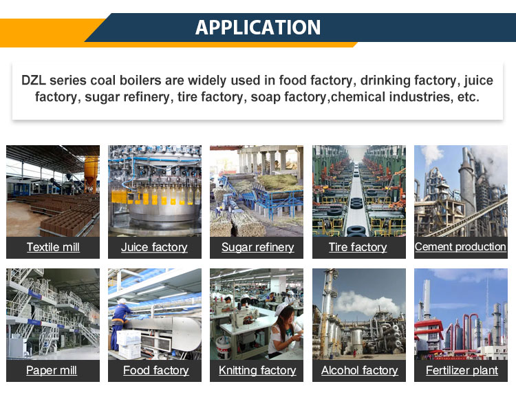
As industrial facilities and power plants seek cleaner, more cost-effective, and fuel-flexible solutions, traditional boiler systems—such as pulverized coal or grate-fired units—often fall short in terms of emission control, fuel adaptability, and efficiency. In contrast, Circulating Fluidized Bed (CFB) boilers offer a modern solution with significant operational and environmental benefits. However, without understanding these advantages, industries may miss the opportunity to improve performance and reduce lifecycle costs.

The main advantages of a Circulating Fluidized Bed (CFB) boiler over traditional boilers include superior fuel flexibility, lower NOx and SO₂ emissions, improved combustion efficiency, reduced operating temperatures, and enhanced load-following capability. CFB boilers can burn a wide range of fuels—such as coal, biomass, and industrial waste—while maintaining consistent performance. Their unique fluidization and recirculation system allows for complete combustion, better heat distribution, and lower environmental impact.

For industries aiming to modernize their steam or power generation systems, CFB technology provides a future-ready platform that balances performance, efficiency, and sustainability.

How does a CFB boiler provide superior fuel flexibility compared to traditional boilers?

Fuel cost, availability, and composition can fluctuate significantly over time—posing a serious challenge to industrial boiler operators reliant on conventional systems designed for a single type of fuel. Traditional pulverized coal or oil-fired boilers require uniform fuel quality and strict operating conditions, making it difficult to switch fuels without performance penalties or equipment modifications. In contrast, the Circulating Fluidized Bed (CFB) boiler is engineered to burn a wide range of fuels efficiently and cleanly, making it one of the most fuel-flexible combustion technologies available in industrial and utility-scale applications.

A CFB boiler provides superior fuel flexibility compared to traditional boilers by utilizing a fluidized combustion process that can efficiently burn a wide range of low-grade, high-moisture, and variable-composition fuels—including coal, biomass, petroleum coke, industrial waste, and RDF (refuse-derived fuel). The system’s ability to maintain uniform bed temperatures, accommodate diverse particle sizes, and adjust air/fuel ratios dynamically allows it to switch between fuels without major hardware changes, ensuring consistent efficiency, stable emissions, and continuous operation under varying fuel conditions.

This unique capability allows plant operators to respond to market fuel fluctuations, reduce operating costs, and utilize locally available or waste-derived energy sources without compromising performance or compliance.

What Makes CFB Boilers Fuel-Flexible?

Design FeatureFuel Flexibility Contribution
Fluidized Bed CombustionAllows thorough mixing of air and fuel for even combustion
Wide Temperature Range (800–900°C)Prevents slagging and enables use of high-ash, low-reactivity fuels
High Solids RecirculationExtends residence time for complete burn of low-grade fuels
Multi-fuel FeedersSupports simultaneous or alternating feeding of different fuels
Integrated Limestone InjectionEnables in-furnace sulfur capture from high-sulfur fuels

Unlike traditional combustion systems, CFB boilers do not require fine pulverization or oil atomization. Fuels can be coarse, wet, variable in calorific value, or heterogeneous, and still burn efficiently within the fluidized environment.

Common Fuels Used in CFB Boilers

Fuel TypeTypical Use in CFB Boiler
Bituminous/Sub-bituminous CoalBaseline fuel in many CFB power plants
LigniteLow-cost, high-moisture coal burned without drying
Petroleum CokeHigh-sulfur, high-energy byproduct fuel
Biomass (wood chips, agri-waste)Co-fired or 100% fired in CFB with low emissions
Sewage Sludge / MSW / RDFWaste-to-energy plants using CFB for recovery
Peat and Torrefied BiomassUsed in fuel-diverse or carbon-neutral projects

Comparison: Fuel Flexibility of Boiler Types

Boiler TypeFuel Flexibility RatingFuel Type Limitations
CFB Boiler★★★★★Can burn diverse solids, sludges, waste, mixes
Pulverized Coal (PC) Boiler★★☆☆☆Requires dry, fine coal
Oil-Fired Boiler★☆☆☆☆Specific to clean liquid fuels
Gas-Fired Boiler★☆☆☆☆Limited to methane or LPG
Grate-Fired Biomass Boiler★★☆☆☆Can burn biomass, but limited fuel variation

The CFB’s ability to co-fire multiple fuels—such as coal with biomass or waste materials—makes it uniquely adaptive in real-world energy scenarios.

Fuel Switching: Operational Stability and Control

CFB boilers can adjust to new fuels without shutdown, thanks to their dynamic combustion control and robust design:

Fuel Property VariationCFB Boiler Response
Moisture Content ↑Longer combustion residence time balances energy
Calorific Value ↓Higher feed rate and bed recirculation compensate
Ash Content ↑Non-slagging temperature avoids deposit issues
Particle Size VariationFluidized bed maintains even combustion

Advanced Distributed Control Systems (DCS) monitor bed temperature, air flow, fuel feed rate, and cyclone performance, automatically adapting combustion parameters.

In-Furnace Emissions Control with Variable Fuels

Fuel flexibility does not compromise environmental compliance in a CFB boiler:

Emission TypeIn-Furnace Control MethodBenefit When Fuel Changes
SO₂Limestone injection (CaCO₃) reacts with sulfurControls sulfur even in high-sulfur fuels
NOxLow-temperature combustion limits thermal NOxNo SCR needed in most cases
ParticulatesCyclone and ESP/baghouse systemsHandles ash from varied fuel types

This built-in emissions management makes CFB boilers suitable for waste-to-energy, biomass co-firing, and low-grade coal use without additional post-combustion scrubbers.

Real-World Case Study: Multi-Fuel Industrial CFB Plant

A 150 MW industrial utility in Eastern Europe installed a CFB boiler to replace aging oil and coal systems. The goal was to reduce fuel costs and comply with EU emissions regulations.

Fuels Used:

  • 60% Lignite

  • 25% Biomass (wheat straw, wood waste)

  • 15% RDF and plastics

Results:

  • Maintained >88% boiler efficiency across fuel variations

  • NOx emissions under 180 mg/Nm³ without SCR

  • SO₂ reduced by 92% via limestone dosing

  • Fuel cost reduced by 37% in first year

This demonstrates how multi-fuel capability lowers costs, enhances flexibility, and supports sustainable operations.

Summary: Fuel Flexibility Benefits of CFB Boilers

Advantage CategoryCFB Boiler Performance
Fuel VarietyBurns solid, liquid, wet, dry, low-grade, and waste fuels
Cost OptimizationEnables use of cheaper or on-site fuels
Resilience to Fuel Supply IssuesEasily switches fuels during market disruptions
Emissions ComplianceBuilt-in SOx and NOx control across fuel types
SustainabilitySupports biomass, waste-derived fuels, and carbon targets

The CFB boiler’s unmatched fuel flexibility makes it an ideal solution for industries facing volatile fuel markets, regulatory pressure, and sustainability mandates. It enables efficient, continuous energy generation—no matter the fuel source.

In what ways do CFB boilers achieve lower emissions than conventional systems?

In an era where industrial emissions are under intense scrutiny, boiler systems must not only deliver energy efficiently but also minimize their environmental footprint. Conventional combustion technologies—such as pulverized coal (PC) boilers, oil-fired systems, or even basic biomass furnaces—often struggle to meet strict regulatory standards without costly post-combustion treatment systems. Circulating Fluidized Bed (CFB) boilers, however, are inherently designed for cleaner combustion, offering multiple mechanisms for reducing pollutants at the source rather than relying solely on end-of-pipe solutions.

CFB boilers achieve lower emissions than conventional systems by utilizing low-temperature combustion (800–900°C), in-furnace sorbent injection for sulfur capture, staged air supply to limit NOx formation, and high-efficiency particulate removal via cyclones and fabric filters. This integrated design minimizes the generation of NOx, SO₂, CO, and particulate matter directly in the combustion chamber, significantly reducing the need for external emission control systems and ensuring compliance with stringent air quality regulations.

This in-furnace control approach makes CFB technology not only environmentally superior but also cost-effective and operationally streamlined.

Breakdown of Emission Reductions in CFB Boilers

Pollutant TypeConventional Boiler IssueCFB Boiler Solution
Nitrogen Oxides (NOx)Formed at high combustion temps (>1,300°C)Lower combustion temp (~850°C) + staged air injection
Sulfur Dioxide (SO₂)Requires post-treatment scrubbersLimestone added in furnace captures sulfur directly
Particulate Matter (PM)Unburned ash or fly ash escapes stackHigh-efficiency cyclones and ESPs remove up to 99.9%
Carbon Monoxide (CO)Caused by uneven combustionLong fuel residence time ensures complete combustion
Heavy Metals & ToxicsReleased from burning waste or poor-quality coalCaptured with fly ash or bound in sorbents inside the bed

1. Low-Temperature Combustion: NOx Reduction

CFB boilers operate at 800–900°C, significantly below the flame temperatures found in PC or oil-fired systems.

FactorConventional BoilerCFB Boiler
Peak Flame Temperature~1,400–1,600°C~850°C
NOx Formation MechanismThermal and fuel NOxMostly suppressed
Typical NOx Emissions300–600 mg/Nm³<150 mg/Nm³, often <100

How it works:

  • Thermal NOx (produced at high temperatures) is nearly eliminated.

  • Staged air (primary + secondary) delays oxidation of nitrogen in fuel.

No need for Selective Catalytic Reduction (SCR) in most applications—saving capital and operating cost.

2. In-Furnace Desulfurization: SO₂ Control

Instead of relying on flue gas scrubbers downstream, CFB boilers inject limestone or dolomite (CaCO₃) directly into the combustion chamber.

Reaction:

CaCO₃ → CaO + CO₂  
CaO + SO₂ → CaSO₃ → CaSO₄
FeatureBenefit
Limestone Injection Ratio~1.5:1 molar (Ca:S)
Desulfurization Efficiency85–95% in-furnace
SO₂ EmissionsOften <100 mg/Nm³ with no scrubber required
Sorbent TypeLimestone, quicklime, dolomite

This embedded sulfur control simplifies plant design and avoids large wet or dry flue gas desulfurization (FGD) units.

3. Particulate Capture via Cyclones and Bag Filters

CFB boilers produce fine ash particles, but their high gas-solid interaction and downstream dust collection systems ensure minimal particulate escape.

Control DeviceEfficiency
Primary Cyclone Separator85–90%
Electrostatic Precipitator (ESP)Up to 99.9%
Fabric Filter / BaghouseUp to 99.95%
Final PM Emissions<10 mg/Nm³, often <5 mg/Nm³

Plus, the fluidization process enhances combustion uniformity—reducing unburned carbon and minimizing particulate generation at the source.

4. Complete Combustion and CO Control

CFB boilers offer longer fuel residence time than conventional units, ensuring even slow-burning fuels combust completely.

ParameterConventional BoilerCFB Boiler
Fuel Residence Time1–2 seconds5–10 seconds (with recirculation)
CO Formation RiskHigher (uneven burn)Lower (complete burnout)
Typical CO Emissions50–100+ mg/Nm³<50 mg/Nm³ (even with biomass)

Long combustion time = cleaner burn = lower CO = higher combustion efficiency.

5. Multi-Fuel and Waste Fuel Emission Control

CFB boilers excel at burning:

  • Biomass

  • Petroleum coke

  • RDF (Refuse-Derived Fuel)

  • Sewage sludge

  • Waste coal

These fuels often contain chlorine, heavy metals, or volatile organics. In a CFB system:

  • Volatile metals are captured in fly ash

  • Chlorine reacts with added sorbents (e.g., kaolin or lime)

  • Organic toxins are destroyed due to long exposure in oxidizing atmosphere

This makes CFB boilers ideal for waste-to-energy and industrial co-firing under strict emission limits.

Real-World Example: Biomass Co-Fired CFB Plant

A 300 MW CFB plant in Scandinavia co-fires wood waste, peat, and refuse-derived fuel.

Emission Results:

PollutantMeasured LevelRegulatory Limit (EU)
NOx85 mg/Nm³150 mg/Nm³
SO₂50 mg/Nm³200 mg/Nm³
Particulate6 mg/Nm³20 mg/Nm³
CO20 mg/Nm³100 mg/Nm³

All without external SCR or FGD systems—just in-furnace control and cyclones.

Summary: How CFB Boilers Achieve Low Emissions

Emission TypeCFB Reduction MechanismResult Compared to Conventional Systems
NOxLow combustion temp + staged airUp to 80% less than PC boilers
SO₂In-bed limestone injectionUp to 95% captured in-furnace
Particulates (PM)Cyclone + ESP/filters + clean burn<10 mg/Nm³, no visible smoke
COLong residence + complete combustionLow CO even with waste fuels
Toxics/Heavy MetalsCaptured with ash or sorbentsSuitable for waste-burning compliance

CFB boilers are not only efficient and versatile—they are also environmentally advanced systems that meet or exceed global emission standards without complex or expensive end-of-pipe controls. For industries seeking a cleaner, more sustainable combustion solution, CFB technology leads the way.

How does the fluidized bed design improve combustion efficiency and heat transfer?

Maximizing combustion efficiency and heat transfer is essential for any industrial boiler system—especially when burning challenging fuels like low-grade coal, biomass, or waste. Traditional combustion systems often suffer from poor fuel-air mixing, hotspots, incomplete burn, and inefficient heat exchange. This leads to fuel waste, higher emissions, and uneven thermal loads. Enter the fluidized bed design, the foundation of Circulating Fluidized Bed (CFB) and Bubbling Fluidized Bed (BFB) boilers, which transforms how fuel is burned and how heat is extracted.

The fluidized bed design improves combustion efficiency and heat transfer by suspending solid fuel particles in a turbulent, high-velocity stream of air, which ensures uniform temperature distribution, excellent fuel-air mixing, prolonged residence time, and intense contact between hot gases, ash particles, and heat transfer surfaces. This results in complete combustion of even difficult fuels, minimized unburned carbon losses, and exceptionally efficient heat extraction to steam or water systems—making fluidized bed boilers highly efficient, clean, and fuel-flexible.

This principle not only enhances performance but also enables the use of diverse, low-cost fuels with consistent energy output and reduced emissions.

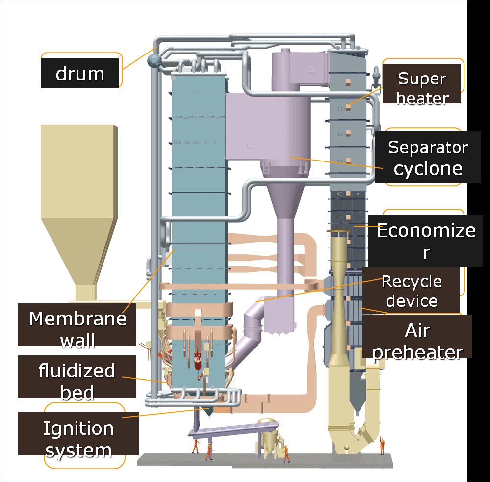
How the Fluidized Bed Works

In a fluidized bed, air is forced upward through a bed of inert material (usually sand, ash, or limestone). When air velocity exceeds the minimum fluidization velocity, the bed behaves like a boiling liquid—lifting and suspending fuel particles in a dynamic, turbulent state.

ComponentFunction
Air Distributor PlateEvenly introduces high-pressure primary air from below
Bed MaterialTransfers heat and stabilizes combustion (e.g., sand, ash)
Fuel Feed SystemIntroduces solid, liquid, or slurry fuel into the bed
Cyclone SeparatorCaptures and recirculates unburned particles for re-burning
Heat Exchange SurfacesExtracts thermal energy into water/steam circuits

Combustion Efficiency Benefits

1. Excellent Fuel-Air Mixing

  • Continuous movement of particles ensures that fuel, air, and hot bed material are evenly mixed.

  • No need for pulverized fuel—even coarse, wet, or variable-size particles can combust fully.

Efficiency FactorTraditional BoilerFluidized Bed Boiler
Fuel-Air ContactLimited (laminar flow)Excellent (turbulent flow)
Mixing UniformityUnevenHigh
Flame ControlFlame zones/hotspotsUniform combustion zone

2. Longer Fuel Residence Time

Fuel particles remain suspended and recirculated in the bed for 5–10 seconds, compared to 1–2 seconds in conventional combustion.

  • Allows complete burnout of volatile matter and char.

  • Enables the combustion of low-reactivity fuels like petcoke, sewage sludge, and biomass.

3. Lower Combustion Temperature

CFBs operate at 800–900°C, below ash fusion points:

  • Prevents slagging and fouling of heat surfaces.

  • Limits thermal NOx formation while maintaining full combustion efficiency (>98%).

4. Auto-Thermal Stability

The bed stores thermal energy, acting as a thermal flywheel:

  • Maintains combustion during load fluctuations.

  • Reduces instability from fuel moisture or quality variation.

Heat Transfer Efficiency Advantages

1. Enhanced Convection and Radiation

  • Fluidized particles rub against heat exchanger surfaces, improving convective heat transfer.

  • Suspended particles and flue gases transfer radiative heat uniformly across the furnace.

Heat Transfer ModeEnhancement in Fluidized Bed Design
ConvectionTurbulence increases surface heat exchange rate
RadiationEven temperature and particle coverage improve absorption
Bed Material ContactSolids conduct heat directly to surfaces

2. Immersed Surface Area in Furnace

Unlike conventional boilers, many CFB units embed heat exchange tubes directly into the combustion bed, accelerating transfer:

  • Evaporator tubes

  • Superheaters

  • Reheaters

This direct contact reduces boiler size for a given output and increases thermal efficiency.

3. Recirculation for Heat Utilization

The cyclone separator captures and recycles hot particles back to the bed:

  • Recaptured energy increases combustion zone temperature without extra fuel.

  • Fuel particles that missed complete combustion are reburned.

Comparison: Heat Transfer Rates

Boiler TypeTypical Heat Transfer Coefficient (kW/m²·K)
Pulverized Coal Boiler100–200
Oil/Gas-Fired Boiler120–180
Fluidized Bed Boiler300–400+

This higher rate means:

  • Faster response to load changes

  • Lower fuel consumption

  • Smaller overall boiler footprint

Real-World Performance Case: Biomass CFB Plant

A biomass CFB boiler (100 MWth) using wood chips and agricultural residues achieved:

  • Combustion efficiency of >99.1%

  • Heat transfer efficiency to steam circuit of 92.8%

  • Bed temperature stability ±10°C under 20% load swings

  • Steam temperature stability within ±1.5°C

No slagging, minimal fouling, and 5-year tube life—well above average.

Summary: Combustion & Heat Transfer Superiority in Fluidized Beds

Performance AreaFluidized Bed Boiler Benefit
Fuel-Air MixingUniform, continuous mixing ensures full combustion
Combustion CompletionHigh residence time and turbulence yield low unburned carbon
Temperature UniformityStable bed temperatures improve control and safety
Heat Transfer RateSuperior due to turbulence and direct contact
Load FlexibilityFast thermal response with thermal buffer effect
Fuel VersatilityCan burn high-moisture, low-grade fuels cleanly

The fluidized bed design transforms combustion into a highly efficient, low-emission, and flexible process, enabling boiler systems to adapt to fuel and load variability without sacrificing performance. For industries seeking cost-effective, sustainable thermal energy, it is a proven high-efficiency solution.

Why do CFB boilers operate more efficiently at lower temperatures?

In conventional boilers—such as pulverized coal or oil-fired systems—high combustion temperatures (often exceeding 1,300–1,500°C) are required to ensure complete fuel burn. However, these elevated temperatures come with significant drawbacks: higher NOx emissions, risk of slagging and fouling, equipment degradation, and reduced fuel flexibility. Circulating Fluidized Bed (CFB) boilers, on the other hand, operate within a lower and more controlled temperature range (typically 800–900°C), and this is not a limitation—it’s a fundamental efficiency-enhancing design feature.

CFB boilers operate more efficiently at lower temperatures because the fluidized bed environment enables complete combustion of a wide range of fuels without needing flame-stabilized high-temperature zones. This moderate and uniform temperature range prevents ash fusion, reduces thermal NOx formation, extends equipment lifespan, and allows better in-furnace heat transfer. The combination of efficient combustion at reduced thermal stress levels leads to high boiler efficiency, lower emissions, and greater operational flexibility—all without the need for costly external pollution control systems.

This innovative low-temperature combustion principle is central to the performance, reliability, and adaptability of CFB technology.

Understanding the CFB Operating Temperature Profile

Temperature RangeSystem Behavior and Benefits
800–900°COptimal combustion temperature for solid fuels in CFBs
Below 1,000°CAvoids ash melting, fouling, and slag formation
Stable FurnaceHeat is evenly distributed across the bed and flue

Unlike flame combustion zones in PC boilers, where temperatures can spike above 1,400°C, CFB boilers burn fuel within a stable bed of suspended particles, using turbulence and residence time rather than peak temperature to achieve complete burn.

Key Efficiency Advantages of Lower Operating Temperatures

1. Reduced Formation of Nitrogen Oxides (NOx)

High flame temperatures (above ~1,200°C) lead to the formation of thermal NOx, a major pollutant.

Boiler TypeTypical Combustion TempNOx Emissions (mg/Nm³)
Pulverized Coal1,300–1,600°C300–500+
Oil-Fired1,300–1,500°C200–400
CFB Boiler850–900°C<100 (low-NOx design)

By operating below this critical NOx formation threshold, CFBs achieve low emissions without SCR or SNCR systems, making the design both clean and cost-efficient.

2. Prevention of Slagging and Fouling

In high-temperature combustion, ash particles can melt and form slag, coating heat transfer surfaces and reducing efficiency.

ConditionPC BoilerCFB Boiler
Ash FusionAbove 1,200–1,300°CAvoided at <950°C
Slag FormationCommon with high-ash coalRare in CFB
Surface FoulingRequires soot blowingMinimal in CFB

Operating below ash fusion temperatures allows CFB boilers to burn high-ash fuels, such as lignite, petcoke, and biomass, without damaging boiler internals or requiring frequent cleaning.

3. Enhanced Heat Transfer Performance

The intense turbulence and fine particle suspension in the fluidized bed create ideal conditions for high-efficiency heat transfer—without needing extreme temperature differentials.

Heat Transfer ModePerformance in CFB Boiler
ConvectionBoosted by particle-to-surface contact
RadiationUniform due to large surface exposure
Bed ContactDirect conduction from hot solids

This efficient heat exchange, even at moderate temperatures, contributes to overall thermal efficiencies of 85–90% or more, especially when combined with economizers and reheaters.

4. Fuel Flexibility and Moisture Tolerance

High temperatures in conventional boilers require dry, consistent fuels. CFBs, thanks to their moderate and stable combustion zone, can:

  • Burn fuels with high moisture content (up to 50%)

  • Handle variable calorific values

  • Mix fuels (coal + biomass + sludge) without destabilizing combustion

This not only improves fuel sourcing flexibility but also supports cost savings and carbon reduction strategies.

5. Lower Mechanical and Thermal Stress

Operating at lower furnace temperatures reduces:

  • Tube metal creep and fatigue

  • Refractory degradation

  • Weld and joint failures

Maintenance FactorHigh-Temp BoilerCFB Boiler (Lower Temp)
Tube Replacement Cycle3–5 years6–10+ years
Refractory SpallingCommonRare
Component LifespanShorter due to thermal stressLonger

This extends boiler life, reduces downtime, and lowers lifecycle maintenance costs.

Real-World Example: Waste-Coal-Fueled CFB Boiler

A 200 MW CFB power plant in Southeast Asia uses low-grade coal with 45% ash content and 30% moisture.

CFB Furnace Conditions:

  • Operating bed temperature: 870°C

  • Heat transfer rate: >350 kW/m²·K

  • Unburned carbon: <1.2%

  • NOx: <80 mg/Nm³, without external treatment

Despite fuel variability, combustion remained stable, ash did not slag, and tubes remained clean after 18 months, requiring only routine maintenance.

Summary: Why Lower Temperatures in CFB = Higher Efficiency

Advantage AreaBenefit from Lower Temperature Operation
NOx Emission ControlThermal NOx minimized—no need for SCR
Ash ManagementPrevents slagging, allows burning high-ash fuels
Heat Transfer EfficiencyExcellent turbulence and surface contact at 800–900°C
Fuel FlexibilityTolerates wet, variable, and low-quality fuels
Boiler DurabilityReduced thermal stress, longer component lifespan

CFB boilers are engineered to make lower combustion temperature an operational advantage rather than a compromise. Through smart design and fluid dynamics, they extract maximum energy from minimal heat, redefining how industrial combustion systems achieve both efficiency and environmental performance.

What makes CFB boilers better suited for variable load conditions?

In many industrial and utility applications, thermal demand is not constant. Processes ramp up and down, grid power requirements fluctuate, and seasonal variation affects heating or steam loads. Traditional boiler systems, particularly pulverized coal (PC) or oil-fired boilers, often struggle under these conditions, experiencing efficiency drops, instability, or even flameouts when loads are rapidly changed. In contrast, Circulating Fluidized Bed (CFB) boilers are inherently stable, flexible, and efficient under variable load conditions, making them ideal for dynamic energy environments.

CFB boilers are better suited for variable load conditions because their fluidized combustion environment maintains stable temperatures, ensures consistent fuel-air mixing, and allows for dynamic control of air, fuel, and recirculated solids. The bed’s thermal inertia, wide turndown ratios, and integrated air staging allow for seamless load adjustments without compromising combustion stability or efficiency. This flexibility enables CFB boilers to operate efficiently across a broad range of output levels, minimizing unburned carbon, reducing emissions, and avoiding mechanical stress from frequent cycling.

Let’s explore the engineering and operational features that make CFB boilers a top performer under fluctuating load profiles.

Key Design Features Supporting Load Flexibility

Design ElementContribution to Load Adaptability
Fluidized Bed CombustionMaintains uniform temperature and combustion distribution
Bed Thermal InertiaActs as a heat buffer, smoothing sudden load changes
Cyclone Separator and Return LoopEnables continuous particle recirculation
Staged Air SupplyIndependently controls combustion zones
Automated Fuel and Air ModulationAdjusts firing rate in real-time

Turndown Ratio Advantage

Turndown ratio is the ratio of maximum to minimum load a boiler can handle while maintaining stable combustion and efficiency.

Boiler TypeTypical Turndown Ratio
Pulverized Coal Boiler3:1 to 4:1
Oil-Fired Boiler4:1 to 6:1
CFB Boiler5:1 to 10:1

This wide load range allows CFB boilers to:

  • Operate at partial loads without cycling

  • Ramp up or down gradually or rapidly

  • Meet base-load, intermediate, or peak-load demands

Thermal Inertia and Bed Stability

The fluidized bed contains a mix of hot ash, fuel particles, and inert material (like sand or limestone), which stores and releases heat gradually.

Load ConditionCFB Response Mechanism
Sudden Load IncreaseHot bed material instantly provides combustion energy
Sudden Load DropReduced fuel feed, but bed retains thermal balance
Fuel Quality VariationBed compensates by adjusting temperature and residence time

Result: CFB boilers maintain combustion efficiency >98% even during rapid transitions, without flame instability or cold-end corrosion.

Real-Time Combustion Control

CFB systems use PLC-based or DCS control systems to continuously monitor and adjust:

  • Primary and secondary airflows

  • Fuel feed rate

  • Bed and furnace pressure

  • Return loop solids circulation

Dynamic Feedback Loop:

Load demand ↑ → Fuel + air ↑ → Cyclone returns more solids → Bed temp stabilizes → Steam output ↑
Load demand ↓ → Fuel + air ↓ → Recirculation slows → Bed temp stabilizes → Steam output ↓

This automation ensures precise control of combustion conditions and heat output at all load levels.

Stable Emissions Under Load Shifts

Unlike conventional boilers that require extra tuning or struggle to meet environmental limits at partial load, CFBs maintain:

Emission TypeCFB Boiler Performance During Load Change
NOxControlled via staged air; stays low
SO₂Limestone dosing adjusts dynamically
COLong residence time prevents spikes
PM (Particulates)Stable cyclone performance

No secondary systems (like SCR/SNCR or FGD) need to be bypassed or paused during load changes, ensuring constant regulatory compliance.

Case Study: District Heating CFB Boiler in Variable Operation

A 120 MWth CFB boiler in Northern Europe serves a district heating network with seasonal and hourly demand swings.

Operating LoadSystem Behavior
100% (Winter Peak)Full fuel feed and limestone injection
60% (Spring/Fall)Reduced air and fuel flow; stable emissions
30% (Summer Idle Mode)Operated in low-load mode for hot water only

Key outcomes:

  • NOx: maintained <100 mg/Nm³ at all loads

  • CO: <30 mg/Nm³, even at 30% load

  • Bed temp fluctuation: ±15°C across full load range

  • Boiler efficiency loss: only 2.5% between 100% and 30% load

Comparison: Load Handling Performance

FeatureConventional BoilerCFB Boiler
Minimum Stable Load~40–50%15–20%
Load Change Response TimeSlow, prone to overshootFast, stabilized by bed
Efficiency at Partial LoadDrops sharplyRemains >90%
Emission StabilityRequires re-tuningAuto-adjusts dynamically
Cycling Wear and TearHighLow (continuous burn)

Summary: Why CFBs Thrive Under Variable Loads

Performance AreaCFB Boiler Advantage
Wide Turndown Ratio5:1 or more—handles base and peak load efficiently
Thermal BufferingBed acts as heat reservoir for smooth transitions
Combustion StabilityMaintains flame-free, uniform burn under all loads
Real-Time ControlAdjusts air, fuel, and recirculation dynamically
Emission ControlLow and stable across load range

CFB boilers provide exceptional load-following capability, enabling industrial users and power generators to respond to fluctuating demand without sacrificing efficiency, emissions, or equipment life. For operations with variable loads, seasonal shifts, or cogeneration needs, CFB technology delivers unmatched adaptability and performance.

How do CFB systems reduce overall operational and maintenance costs?

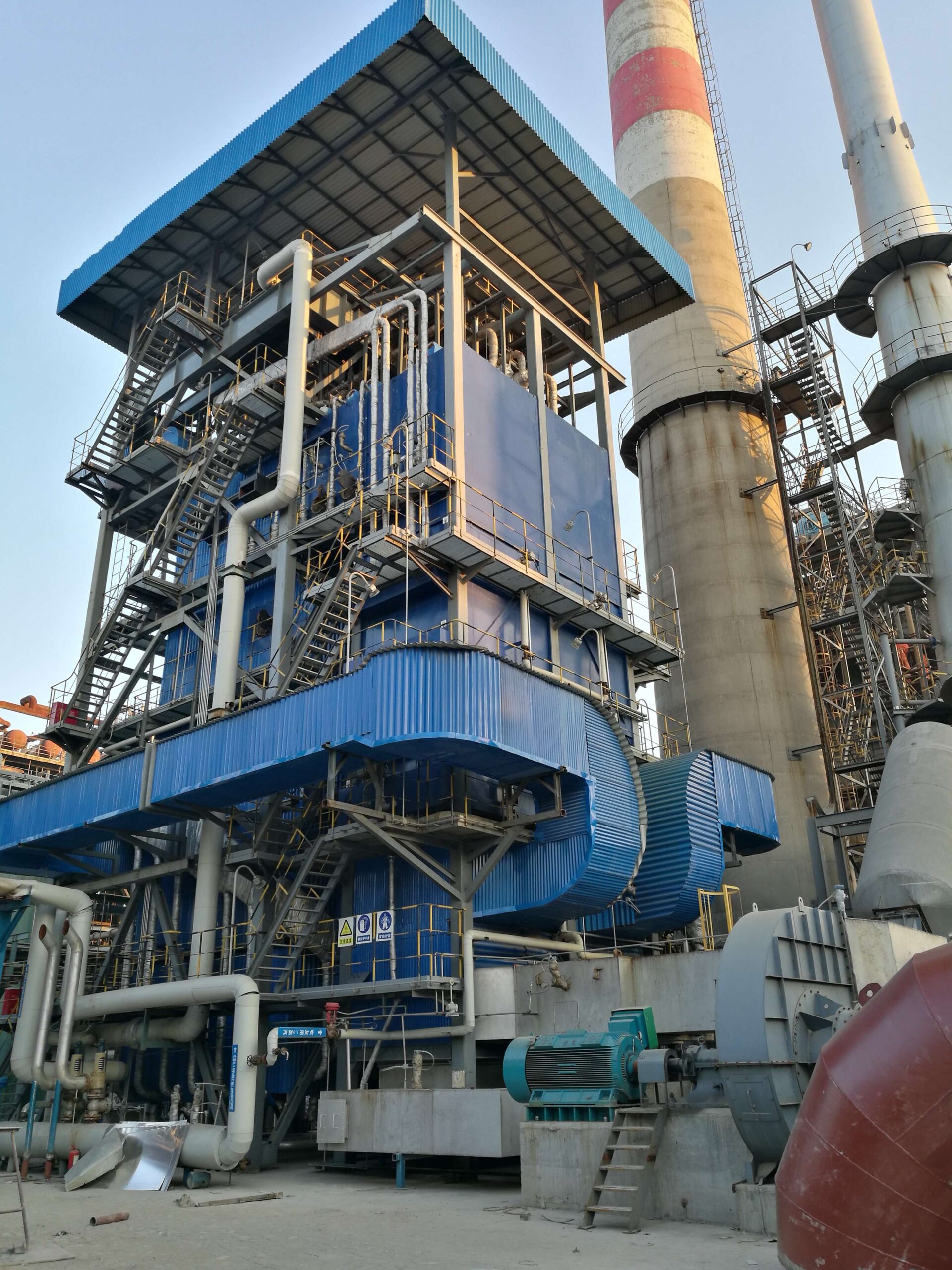
![CFB boiler cost-saving operational diagram]
Prompt: Circulating Fluidized Bed (CFB) boiler system showing cost-saving features like in-furnace desulfurization, low-temperature combustion, high-ash fuel compatibility, and minimized fouling + industrial maintenance technician inspecting clean boiler tubes + cost-efficient and sustainable mood + bright industrial lighting

In large-scale industrial and utility energy systems, fuel cost, maintenance downtime, and emissions control expenses are significant contributors to total cost of ownership. Traditional combustion technologies like pulverized coal (PC), oil-fired, or stoker boilers often require complex fuel preprocessing, intensive maintenance cycles, and additional emission treatment systems—leading to high operational expenditures (OPEX) and frequent shutdowns. Circulating Fluidized Bed (CFB) systems, on the other hand, are engineered for fuel flexibility, thermal stability, and in-furnace pollution control, which collectively reduce the total cost burden of energy generation.

CFB systems reduce overall operational and maintenance costs by enabling the use of low-cost, variable-quality fuels, minimizing ash and slag-related fouling, eliminating the need for external emission scrubbers, and reducing thermal stress through low-temperature combustion. These features translate to longer equipment life, reduced maintenance frequency, and lower labor requirements. Additionally, stable combustion and heat transfer lower fuel consumption and support continuous operation with minimal unscheduled downtime.

Let’s break down the specific ways CFB technology achieves superior economic efficiency compared to conventional boiler systems.

1. Fuel Cost Savings Through Fuel Flexibility

CFB boilers are capable of burning a wide variety of low-cost fuels, including:

  • Low-grade coal

  • Lignite

  • Petroleum coke

  • Biomass residues

  • Refuse-derived fuel (RDF)

  • Industrial sludge and waste

Cost Impact AreaConventional BoilerCFB Boiler Benefit
Fuel PreprocessingPulverizing, dryingMinimal or none (tolerates high moisture)
Fuel Cost per GJHigher-grade fuels onlyUses cheapest available fuels
Fuel Switching FlexibilityLimitedSeamless with co-firing capability

Estimated Fuel Savings:
Facilities using CFB boilers report fuel cost reductions of 20–40% when switching from oil or pulverized coal to mixed biomass or waste fuels.

2. Lower Maintenance Frequency and Downtime

CFB systems operate at lower combustion temperatures (800–900°C), preventing slagging and corrosion. This reduces wear and damage to critical components:

ComponentCommon Maintenance IssueCFB Mitigation Strategy
Boiler TubesSlag buildup, erosionEven heat transfer + clean combustion
Refractory LiningSpalling from heat shockLower temperature, stable load response
Superheater SurfacesFouling due to ashLower particulate carryover, cyclone return
Air FansDust wear from ashLower particulate content + efficient cyclone

Maintenance Interval Comparison:

System TypeMajor Maintenance CycleTypical Downtime (Annual)
Pulverized CoalEvery 6–12 months2–4 weeks
Oil-Fired9–12 months1–2 weeks
CFB Boiler18–36 months<1 week

3. Reduced Need for External Emissions Controls

CFB boilers incorporate in-furnace sulfur and nitrogen control, eliminating or minimizing the need for expensive post-combustion technologies.

Emission TypeConventional ControlCFB Control Mechanism
SO₂Flue Gas Desulfurization (FGD)Limestone injection in bed
NOxSelective Catalytic Reduction (SCR)Staged air + low-temp combustion
ParticulatesBaghouse or ESPCyclone separator + optional baghouse

Cost Impact:

Control EquipmentEstimated CAPEX/OPEX Reduction
FGD SystemSaved 10–15% of total plant CAPEX
SCR CatalystEliminated $1–3 million lifecycle cost
Sootblowers and Ash HoppersReduced maintenance hours by 50%

4. High Availability and Runtime Efficiency

CFB boilers are designed for continuous operation even under fuel or load variability.

Operational AdvantageCost-Saving Outcome
Stable CombustionFewer shutdowns, reduced restart fuel consumption
Automatic Control SystemsReduced operator labor and tuning requirements
High Turndown Ratio (up to 10:1)Operates efficiently during partial load conditions

This leads to availability rates of over 95%, which is especially important in baseload or cogeneration plants where interruptions are costly.

5. Simplified Ash Handling and Disposal

Due to the complete combustion and stable bed conditions in CFBs:

  • Unburned carbon content in ash is <1%

  • Ash is dry and uniform, making it easier to handle

  • Reduced slag formation prevents manual cleaning or clinker removal

Some CFB-generated ash is even suitable for use in cement, road base, or agricultural applications, reducing disposal costs.

Case Example: Industrial Utility Plant (Eastern Europe)

A 120 MWth CFB boiler replaced three aging stoker-fired units burning lignite.

MetricBefore (Stoker)After (CFB Boiler)
Fuel Cost (€/MWh)18.412.2
Maintenance Days/Year30+8
SO₂ Removal System Cost€5.5 million€0.8 million (limestone only)
Staff Required per Shift42

Annual savings exceeded €1.2 million, with full payback in 4.5 years.

Summary: CFB’s Operational and Maintenance Cost Advantages

Cost CategoryHow CFB Boilers Reduce Cost
Fuel ProcurementBurns low-cost, locally sourced or waste fuels
Combustion EfficiencyComplete burn reduces unburned losses
MaintenanceFewer shutdowns, longer component life
Emissions ControlBuilt-in NOx and SO₂ mitigation
Labor and OperationReduced operator workload through automation
Ash DisposalCleaner, lighter ash requires minimal handling

By integrating fuel flexibility, low-emission design, and reduced maintenance overhead, CFB systems deliver robust economic performance for industries seeking low-cost, clean, and reliable heat or power generation. For facilities facing fuel price volatility and rising environmental compliance costs, CFB boilers offer a smart, long-term investment.

🔍 Conclusion

Circulating Fluidized Bed boilers offer a next-generation solution for industrial and utility-scale energy production. Compared to traditional boilers, CFB systems deliver better fuel adaptability, cleaner emissions, and more efficient thermal performance. Their ability to burn diverse fuels at lower temperatures with minimal environmental impact makes them ideal for industries focused on sustainable, flexible, and long-term boiler solutions.

📞 Contact Us

💡 Thinking about upgrading to a CFB boiler? Our team of experts can help you assess feasibility, design the right solution, and unlock the full potential of this advanced technology.

🔹 Contact us today to take your boiler system to the next level with CFB technology! 🔄🔥🌱

FAQ

Why are CFB boilers more efficient than traditional boilers?

CFB boilers ensure complete combustion at lower temperatures, resulting in improved thermal efficiency, better heat transfer, and reduced energy losses compared to conventional boilers.

What makes CFB boilers environmentally friendly?

CFB technology naturally reduces NOx emissions due to low combustion temperatures and allows in-bed desulfurization using limestone, significantly cutting SO₂ emissions without costly external scrubbers.

How do CFB boilers offer better fuel flexibility?

CFB boilers can efficiently burn a wide range of low-grade fuels including biomass, coal, petroleum coke, and industrial waste, making them highly adaptable and cost-effective.

Are CFB boilers more cost-effective in the long run?

Yes, their ability to use cheaper fuels, reduced need for external emission control, and high combustion efficiency lower operational and maintenance costs over time.

Do CFB boilers handle variable load demands better?

CFB boilers have excellent load-following capabilities, making them suitable for power plants and industrial applications where energy demand fluctuates frequently.

References

  1. CFB Boiler Technology and Benefitshttps://www.energy.gov

  2. CFB vs Traditional Boilers Comparisonhttps://www.sciencedirect.com

  3. Fuel Flexibility in CFB Combustionhttps://www.researchgate.net

  4. Emission Control with CFB Boilershttps://www.epa.gov

  5. High-Efficiency Combustion Systemshttps://www.bioenergyconsult.com

  6. Operational Cost of CFB vs Conventional Boilershttps://www.mdpi.com

  7. Desulfurization in CFB Technologyhttps://www.energysavingtrust.org.uk

  8. CFB Boiler Load Managementhttps://www.iea.org

  9. Waste-to-Energy Applications of CFBhttps://www.automation.com

  10. Future Trends in CFB Boiler Designhttps://www.sciencedirect.com

Wade Zhang

CEO of Taishan Group Taian Boao International Trade Co., Ltd. 30 years experience in Global industrial boiler market,  Over 300 boiler projects experience, including 21+ EPC projects. Projects span 30+ countries & regions, involving industries such as nuclear power, energy & electricity, municipal heating, mining, textiles, tires etc.

Top Advantages of Circulating Fluidized Bed Boilers Over Traditional Boilers Read More »

What Are the Main Advantages of an Industrial Gas-Fired Boiler Over Traditional Boilers?

What Are the Main Advantages of an Industrial Gas-Fired Boiler Over Traditional Boilers?

Industrial operations demand heating systems that deliver high efficiency, reliability, and environmental compliance. Traditional boilers—especially those powered by coal or oil—often struggle with higher emissions, complex maintenance, and limited automation. In contrast, gas-fired boilers have emerged as a preferred solution due to their clean-burning nature, advanced technology integration, and operational flexibility. For industries focused on energy efficiency and sustainability, understanding the advantages of gas-fired boilers is critical for making the right investment.

The main advantages of an industrial gas-fired boiler over traditional boilers include higher thermal efficiency, significantly lower emissions, cleaner combustion, reduced maintenance, faster startup, and advanced automation compatibility. Gas-fired systems also support greater fuel consistency and combustion control, making them ideal for industries aiming to reduce their carbon footprint while achieving stable and cost-effective heat generation.

For industries seeking a balance of performance, compliance, and operational simplicity, gas-fired boilers offer a superior alternative to conventional systems. Let’s explore their benefits in more detail.

How do gas-fired boilers achieve higher thermal efficiency than traditional systems?

In modern industrial and commercial settings, achieving high thermal efficiency is not only about reducing energy costs—it’s essential for environmental compliance, operational competitiveness, and system sustainability. Traditional boiler systems, particularly those using coal, biomass, or outdated oil technologies, often lose a substantial portion of energy through hot flue gases and incomplete combustion. By contrast, gas-fired boilers, especially those equipped with condensing technology, are designed to extract more usable heat from the same amount of fuel—resulting in superior thermal performance, reduced emissions, and lower operational costs.

Gas-fired boilers achieve higher thermal efficiency than traditional systems by utilizing clean-burning fuels (like natural gas), optimizing air-to-fuel ratios through automated controls, and recovering latent heat from water vapor in flue gases via condensing technology. These features allow modern gas-fired systems to reach efficiency levels of 90–98%, compared to 70–85% for conventional boilers. The combination of complete combustion, advanced heat exchangers, and intelligent control ensures minimal energy waste and maximum steam or hot water output per unit of fuel.

This makes gas-fired boilers especially advantageous in industries where efficiency, responsiveness, and emissions control are top priorities.

Key Technologies That Improve Thermal Efficiency in Gas-Fired Boilers

FeatureEfficiency Contribution
High-efficiency burnersEnsure complete combustion and low excess air
Condensing heat exchangersRecover latent heat from water vapor in exhaust gases
Modulating burners and controlsAdjust output to match demand and minimize cycling losses
Oxygen trim and feedback loopsMaintain optimal air-fuel ratios in real time
Low flue gas temperaturesReduce stack heat loss and improve heat recovery

Condensing Technology: The Core Efficiency Booster

In traditional boilers, flue gas exits at 150–250°C, carrying away unrecovered latent heat from water vapor formed during combustion. In a condensing gas-fired boiler, the flue gas is cooled below the dew point (~55°C), causing the water vapor to condense and release additional heat, which is captured by a secondary heat exchanger.

Heat Recovery Process:

  1. Natural gas (primarily methane) combusts to form CO₂ and H₂O vapor.

  2. Condensing section cools exhaust gas, recovering latent heat of vaporization.

  3. This extra heat is transferred to the incoming feedwater.

ParameterNon-Condensing BoilerCondensing Gas Boiler
Flue Gas Exit Temp180–250°C40–65°C
Efficiency (Higher Heating Value)80–88%90–98%
Stack Loss15–20%4–7%

Combustion Efficiency and Burner Control

Modern gas-fired boilers use premix or fully modulating burners that deliver precise fuel-air mixtures for efficient combustion. These systems minimize unburned hydrocarbons and excess air, two major sources of efficiency loss in traditional systems.

Burner TypeDescriptionEfficiency Benefit
Modulating BurnersAdjust flame size to match loadReduces on-off cycling
Low-NOx Premix BurnersMix air and fuel before ignitionEnsures cleaner, more complete burn
Oxygen Trim ControlsMonitor flue gas O₂ and adjust air flowMaintains ideal combustion ratio

Integrated Economizers and Heat Exchangers

Most modern gas-fired boilers are equipped with economizers, which recover heat from flue gas to preheat feedwater. This reduces the load on the boiler’s main heat exchanger and increases net efficiency.

ComponentRole in Efficiency Improvement
Primary Heat ExchangerTransfers combustion heat to water or steam
Secondary Condensing Heat ExchangerRecovers latent heat from flue gas
Feedwater EconomizerPreheats incoming water to reduce burner load

Together, these systems reduce the amount of energy required to bring feedwater to boiling point, which is one of the most energy-intensive stages in steam production.

Efficiency vs Load Profile

Unlike traditional systems, which lose efficiency at partial loads, gas-fired boilers maintain high performance across a wide turndown range.

Load ConditionTraditional Boiler EfficiencyGas-Fired Boiler Efficiency
100% Load80–85%95–98% (condensing)
50% Load65–75%90–95% (with modulating control)
25% Load55–65%88–92% (minimal cycling loss)

Environmental and Cost Benefits

MetricTraditional BoilerGas-Fired Condensing Boiler
CO₂ Emissions (kg/GJ)~95–100~50–55
Fuel Use per Output UnitHigher~10–20% lower
Maintenance FrequencyMore (due to fouling/soot)Less (clean combustion)
NOx EmissionsHigh (requires SCR/SNCR)Low with low-NOx burner
Operating CostHigher (per kWh of heat)Lower due to high efficiency

Real-World Example: Gas-Fired Upgrade in Textile Factory

A textile dyeing facility replaced three aging 3 TPH coal-fired boilers with two 2.5 TPH condensing natural gas-fired boilers.

Results:

  • Thermal efficiency improved from 78% to 94.2%

  • Fuel cost dropped by 18% annually

  • Boiler room floor space reduced by 30%

  • CO₂ emissions reduced by 21%

The system was integrated with a central control platform and supported variable steam demand, making it ideal for the factory’s production cycles.

Summary: Why Gas-Fired Boilers Are More Thermally Efficient

Efficiency DriverDescription
Complete CombustionClean-burning fuel with minimal unburned waste
Condensing Heat RecoveryCaptures latent heat from exhaust gas
Advanced Burner ModulationMatches output with demand without cycling
Flue Gas Heat UtilizationEconomizers and preheaters reduce energy losses
Low Excess Air OperationMinimizes dilution and stack temperature

Gas-fired boilers, especially condensing models, maximize every calorie of input energy. Their high turndown capability, low emissions, and simplified controls make them the standard for high-efficiency industrial heating and steam systems in the 21st century.

In what ways do gas-fired boilers reduce emissions compared to coal or oil boilers?

In industrial and commercial heating, environmental compliance is no longer optional—it’s a critical requirement. Emissions from boiler systems are a primary source of air pollutants such as sulfur dioxide (SO₂), nitrogen oxides (NOx), carbon monoxide (CO), particulate matter (PM), and carbon dioxide (CO₂). Traditional boilers that burn coal or oil are major contributors to these emissions, often requiring complex and expensive after-treatment systems. Gas-fired boilers, by contrast, offer a fundamentally cleaner combustion profile, reducing air pollution significantly at the source.

Gas-fired boilers reduce emissions compared to coal or oil boilers by producing significantly lower levels of particulate matter, sulfur dioxide, and carbon dioxide due to the cleaner-burning nature of natural gas. Advanced combustion technologies and low-NOx burners in gas systems further minimize nitrogen oxide formation, while the absence of solid combustion residues eliminates ash and heavy metal pollution. This makes gas-fired boilers inherently more environmentally friendly, often eliminating the need for costly emission control equipment required in coal or oil systems.

This clean combustion advantage not only meets today’s environmental standards but also future-proofs facilities against tightening air quality regulations.

Comparative Emissions: Gas vs. Coal vs. Oil

Emission TypeCoal-Fired BoilerOil-Fired BoilerGas-Fired Boiler
Particulate Matter (PM)High (fly ash, soot)Moderate (some soot, heavy oils)Very low (negligible)
Sulfur Dioxide (SO₂)High (1–3% sulfur coal)Moderate (varies by oil type)Very low (<0.01%)
Nitrogen Oxides (NOx)High (thermal and fuel NOx)Moderate (with proper control)Low (with low-NOx burners)
Carbon Monoxide (CO)Moderate (incomplete burn)ModerateLow (complete combustion)
Carbon Dioxide (CO₂)Very high (highest carbon content)HighLower (per energy unit)
Heavy Metals & ToxinsMercury, lead, arsenicTrace amounts (especially in heavy oils)None

Chart: Emissions per GJ of Heat Produced

Emissions (g/GJ)
|
|         Coal     Oil     Gas
| PM      ██████   ███     █
| SO₂     ██████   ███     █
| NOx     █████    ███     ██
| CO      ███      ██      █
| CO₂     ██████   ████    ███

Why Natural Gas Burns Cleaner

Natural gas, primarily methane (CH₄), is a hydrocarbon with:

  • High hydrogen-to-carbon ratio, producing more water vapor and less CO₂

  • No sulfur or ash content, eliminating SO₂ and particulate emissions

  • Stable molecular structure, enabling near-complete combustion

These properties give gas-fired boilers a distinct emission advantage at the chemical level.

PropertyGas (CH₄)Oil (C10–C20+)Coal (C135H96O9NS)
Hydrogen-to-Carbon Ratio~4:1~2:1~0.7:1
Sulfur ContentNegligible0.1–2%0.5–3%
Ash Content0%Traces (in heavy oils)5–20%

Specific Emission Reductions with Gas

1. Particulate Matter (PM)

  • Gas-fired boilers produce near-zero PM, as combustion leaves no solid residue.

  • Coal and heavy fuel oil produce fly ash, soot, and unburned carbon particles.

2. Sulfur Dioxide (SO₂)

  • Natural gas contains no sulfur, so it does not generate SO₂.

  • Coal and high-sulfur oils may require scrubbers or desulfurization units to comply with regulations.

3. Nitrogen Oxides (NOx)

  • Gas systems use low-NOx burners, flue gas recirculation (FGR), or staged combustion to minimize NOx.

  • Coal systems require Selective Catalytic Reduction (SCR) or SNCR to achieve similar results.

NOx Control ComparisonGas-Fired BoilerCoal/Oil Boiler
Base NOx EmissionsLow (with premix burners)High
Control Equipment NeededMinimal (often internal)Extensive (SCR, SNCR)
MaintenanceLowHigh

4. Carbon Dioxide (CO₂)

  • For each GJ of energy, natural gas emits ~50–55 kg CO₂, compared to 90–100 kg for coal.

  • This represents a 40–45% CO₂ reduction—key for meeting decarbonization goals.

Maintenance and Compliance Implications

FactorGas-Fired BoilerCoal/Oil-Fired Boiler
Stack Cleanup EquipmentOften not requiredMandatory (ESP, baghouse, scrubber)
Emission Monitoring SystemSimple (NOx and O₂ sensors)Complex (multi-gas CEMS)
Permitting and InspectionsEasierStringent
Operating Cost (for emissions)Lower (fewer components)Higher (chemical reagents, filter bags)

Real-World Example: Food Processing Plant Conversion

A food processing plant in Southern Europe converted its 5 MW oil-fired boiler to a gas-fired condensing unit.

Before (Oil):

  • SO₂ emissions: 350 mg/Nm³

  • PM: 75 mg/Nm³

  • NOx: 180 mg/Nm³

After (Gas):

  • SO₂: <10 mg/Nm³

  • PM: <5 mg/Nm³

  • NOx: 95 mg/Nm³ (with low-NOx burner)

Result:

  • Compliant with EU IED standards

  • Eliminated use of external scrubber system

  • Reduced air permit complexity and insurance premiums

Summary: Clean-Burning Advantages of Gas-Fired Boilers

Emission TypeReduction with Gas (vs. Coal/Oil)
Particulate Matter90–99%
Sulfur Dioxide99–100%
Nitrogen Oxides30–60% (with advanced burners)
Carbon Dioxide20–45% per GJ of heat
Heavy MetalsEliminated

Gas-fired boilers represent the cleanest combustion option among fossil fuels, offering superior environmental performance with minimal post-treatment requirements. For industries aiming to reduce their environmental footprint, simplify compliance, and align with net-zero targets, switching to gas-fired systems is a strategic and impactful step forward.

How does cleaner combustion in gas boilers impact system longevity and maintenance?

In industrial and commercial boiler operations, equipment longevity and maintenance frequency are vital to cost control and system reliability. Traditional boilers that burn coal, oil, or biomass often suffer from fouling, corrosion, and abrasive deposits due to incomplete or dirty combustion. This results in increased maintenance effort, more frequent shutdowns, and shortened component life. In contrast, gas-fired boilers—especially those burning natural gas—provide an inherently cleaner combustion process, resulting in less contamination, fewer mechanical stresses, and longer-lasting, more dependable boiler systems.

Cleaner combustion in gas boilers significantly improves system longevity and reduces maintenance needs by minimizing soot formation, preventing corrosive residue buildup, and reducing thermal stress on components. Natural gas combustion produces negligible particulate matter, virtually no ash, and low sulfur content, which keeps heat exchanger surfaces, burners, and flue passages cleaner for longer periods. This leads to fewer maintenance cycles, less wear on critical parts, extended operational life, and lower lifecycle costs.

By ensuring that internal surfaces stay clean and system parameters remain stable, gas-fired boilers become more reliable, predictable, and cost-effective across years of operation.

Key Impacts of Clean Combustion on System Durability

Area AffectedImpact of Cleaner Combustion in Gas Boilers
Heat ExchangersRemain free of soot and slag, preserving heat transfer rates
BurnersLess coking, easier ignition, longer lifespan
Flue Gas PathNo ash deposition, reduced corrosion risks
Boiler TubesLess scaling and fouling, minimizing overheating
Fans and DampersLower dust loading, reducing wear and imbalance
Sensors and ControlsCleaner atmosphere preserves sensor accuracy

Comparison of Combustion Byproducts

Combustion ByproductCoal-Fired BoilerOil-Fired BoilerGas-Fired Boiler
Soot and Carbon DepositsHigh (requires regular removal)Moderate (especially with heavy oil)Negligible
Ash and SlagVery high (solid residue)Trace amountsNone
Sulfuric Acid MistHigh (needs neutralization)ModerateMinimal (low S content)
Corrosive CompoundsChlorides, sulfatesVaries by oil gradeVery low

Natural gas contains no ash-forming components and burns with a blue flame—indicating complete combustion with minimal residue.

Maintenance Frequency and Time Comparison

Maintenance ActivityCoal/Oil-Fired BoilerGas-Fired Boiler
Soot BlowingDaily to weeklyRarely needed
Tube CleaningMonthly or quarterlySemi-annually or annually
Burner Inspection/ServiceMonthlyEvery 6–12 months
Flue Gas CleaningRoutineMinimal
Downtime for Cleaning2–4 weeks/year<1 week/year

Cleaner combustion means less frequent maintenance interventions, saving labor and reducing downtime.

Longer Component Lifespan

Gas-fired boilers experience less mechanical and chemical stress, which extends the life of key components:

ComponentLifespan in Coal/Oil BoilerLifespan in Gas Boiler
Burner Assembly3–5 years7–10+ years
Refractory LiningWears due to slag and flame impingementMinimal wear (cooler flame zones)
Boiler TubesRisk of pitting and scalingReduced corrosion and erosion
Flue Stack InternalsCorrosion from SO₂/acid dewClean flue reduces replacement rate

Real-World Case Study: Commercial Laundry Facility

A laundry plant switched from an oil-fired to a natural gas-fired condensing boiler (2.5 TPH capacity):

Before:

  • Weekly burner cleaning

  • Quarterly firetube brushing

  • Annual tube replacement due to corrosion

  • 2–3 days of maintenance downtime/month

After:

  • Annual burner check

  • Semi-annual visual inspection

  • Zero internal cleaning required after 1 year

  • Less than 1 day/year in downtime

Result: Maintenance cost savings of over 40% annually and increased equipment availability.

Impacts on Boiler Control and Efficiency

Clean combustion also improves control stability:

System ElementGas Boiler Benefit
O₂ SensorsUnaffected by soot, maintain calibration
Temperature ProbesLess exposure to corrosive deposits
Flow MetersNo particulate-induced clogging
Combustion ControlsRespond precisely to clean flame patterns

This ensures better real-time efficiency management and safer operation over long intervals.

Summary: Maintenance and Longevity Advantages of Gas-Fired Boilers

Advantage AreaGas Boiler Contribution
Fouling and CleaningMinimal fouling means less frequent cleaning
Component DurabilityLess corrosion, erosion, and thermal stress
Maintenance IntervalsExtended—typically 1 or 2 times/year
Operational AvailabilityHigher uptime due to fewer cleaning shutdowns
Sensor and System ReliabilityClean environment extends life of controls and instruments

The clean-burning nature of gas-fired boilers directly translates into longer-lasting, lower-maintenance systems. For industries that value uptime, predictive maintenance, and long equipment life cycles, natural gas combustion is the most efficient and sustainable choice among fossil fuel technologies.

Why are gas-fired boilers faster and easier to operate than conventional models?

In high-demand industrial and commercial environments, operational speed and ease of use are critical. Boilers that take hours to start up, require manual tuning, or demand constant monitoring not only delay production but also increase labor costs and the risk of system faults. Traditional coal- and oil-fired boilers typically rely on complex fuel-handling equipment, manual ignition, and extensive warm-up procedures. In contrast, gas-fired boilers are designed for simplicity, speed, and automation, making them far more responsive and user-friendly.

Gas-fired boilers are faster and easier to operate than conventional models due to their automatic ignition systems, clean-burning fuel, simplified startup processes, and fully integrated digital controls. Unlike coal or heavy-oil boilers, gas systems eliminate the need for manual fuel handling, long warm-up times, and soot management. With modulating burners, programmable control panels, and remote monitoring, gas boilers can achieve full operation in under 30 minutes and adjust dynamically to load demands with minimal operator input.

These features make gas-fired boilers especially suitable for facilities that require flexible, low-labor, high-uptime thermal systems.

Key Operational Advantages of Gas-Fired Boilers

FeatureOperational Benefit
Instantaneous ignitionNo manual lighting or prolonged warm-up cycles
Fully modulating burnersSmooth and automated load response
Digital control panelsSimple user interface for operators
No fuel prep or handlingNo conveyors, crushers, or pumping systems needed
Low startup timeFast to pressure and temperature
Cleaner combustionNo ash, no soot—less need for maintenance during operation

Startup Time Comparison

Boiler TypeTypical Cold Start TimeWarm Start Time
Gas-Fired Boiler10–30 minutes5–15 minutes
Oil-Fired Boiler30–60 minutes15–30 minutes
Coal-Fired Boiler1.5–3 hours45–90 minutes
Biomass Boiler1–2 hours30–60 minutes

Gas-fired systems can reach full steam output quickly thanks to:

  • Pre-programmed startup sequences

  • Rapid burner ignition via spark or flame ionization

  • Quick heat transfer through clean heat exchangers

  • Pre-purged fuel lines and pilot-less ignition systems

User-Friendly Control Interfaces

Modern gas-fired boilers are equipped with integrated touchscreen HMIs or PLC-based interfaces that provide:

  • Real-time status of pressure, temperature, and burner status

  • Automated scheduling (start/stop based on time or load)

  • Safety interlocks and fault alerts

  • Remote access via SCADA or IoT

This automation reduces the skill level and manual effort required to operate the boiler.

Interface FeatureOperator Benefit
Touchscreen dashboardsEasy-to-read metrics and controls
Auto-start programsHands-free operation at shift start
Alert systemsPrevents faults before they escalate
Remote monitoringAccess and adjust from off-site locations

Burner Modulation and Load Matching

Gas-fired burners often support turndown ratios up to 10:1, allowing the boiler to respond to fluctuating steam or hot water demands without cycling.

Comparison MetricConventional BoilerGas-Fired Boiler
Turndown Ratio2:1 to 4:15:1 to 10:1
Cycling FrequencyHigherLower (modulating control)
Operator AdjustmentsFrequent (manual valves)Minimal (auto adjustment)

Less cycling means:

  • Lower thermal stress

  • Improved fuel efficiency

  • Longer component life

Reduced Complexity and Operator Workload

Operating RequirementTraditional ModelsGas-Fired Boilers
Fuel HandlingManual feed, ash removalNone—piped gas supply
IgnitionManual or stagedInstant, auto-sequenced
Combustion AdjustmentManual dampers or valvesAutomatic via sensors
Startup ChecklistDozens of itemsFew automated checks
Supervision NeededFull-time operatorMinimal (often remote)

Gas boilers can even be networked with Building Management Systems (BMS) for fully integrated energy control across entire facilities.

Case Example: Retrofit in a Food Processing Plant

A food packaging facility replaced a 4 TPH coal-fired boiler with a 3.5 TPH fully modulating gas boiler with smart controls.

Results:

  • Startup time reduced from 2 hours to 18 minutes

  • Operator time cut by 65%

  • Load matching improved steam stability

  • Enabled unattended night operation via remote alarm system

Summary: Operational Simplicity of Gas-Fired Boilers

Area of OperationGas Boiler Advantage
Startup SpeedFast ignition, minimal warm-up
User InterfaceIntuitive touchscreen or PLC control
Burner ControlFully modulating with precise load tracking
Labor RequirementsLow—no ash or fuel handling
System IntegrationEasy to tie into plant automation platforms

Gas-fired boilers offer a combination of speed, simplicity, and smart control unmatched by traditional boiler systems. For facilities seeking minimal disruption, high responsiveness, and reduced operating overhead, they are the go-to solution for modern thermal energy needs.

What role does automation play in enhancing gas-fired boiler performance?

In today’s industrial landscape, where energy efficiency, emission control, and operational uptime are critical KPIs, relying on manual boiler management is no longer viable. Traditional systems that require constant operator intervention are prone to human error, inefficiency, and delayed fault response. Gas-fired boilers, especially when integrated with advanced automation systems, offer a transformative performance advantage—enabling intelligent control, real-time diagnostics, and optimized fuel utilization. Automation doesn’t just simplify operation; it maximizes boiler efficiency, reliability, and regulatory compliance.

Automation plays a central role in enhancing gas-fired boiler performance by continuously optimizing combustion conditions, regulating output in real-time, reducing fuel consumption, and ensuring consistent steam or hot water generation. Through programmable logic controllers (PLCs), digital sensors, modulating burners, and SCADA or IoT platforms, automation minimizes manual intervention, prevents performance drift, and extends equipment life. The result is a highly responsive, energy-efficient, and low-maintenance system tailored to modern industrial demands.

Let’s explore how automation influences every key operational aspect of a gas-fired boiler—from ignition and modulation to monitoring and maintenance.

Core Functions of Automation in Gas-Fired Boilers

Automation FunctionImpact on Boiler Performance
Combustion ControlMaintains optimal air-fuel ratio for maximum efficiency
Burner ModulationAdjusts flame output based on real-time demand
Temperature & Pressure RegulationPrevents overshoot, improves steam/hot water stability
Startup and Shutdown SequencingEnsures safe and fast transitions
Fault Detection and AlertsEnables predictive maintenance and immediate troubleshooting
Remote Monitoring & DiagnosticsReduces operator dependency, allows 24/7 oversight

Burner Modulation and Efficiency Optimization

Gas-fired boilers use fully modulating burners that can operate at varying firing rates (typically 10:1 turndown), controlled automatically based on real-time feedback from sensors.

Sensor InputAutomated Response
Steam pressure dropIncreases burner firing rate
Flue gas temperature riseAdjusts combustion air to reduce heat loss
Excess O₂ detectionFine-tunes air dampers to avoid fuel waste

This precise modulation prevents unnecessary on-off cycling (common in staged systems), which improves:

  • Fuel efficiency (up to 98%)

  • Equipment longevity

  • Combustion stability

Real-Time Monitoring and Smart Control

Modern gas-fired boilers are equipped with:

  • Temperature and pressure transmitters

  • Oxygen and CO₂ sensors in the flue gas

  • Water level and flow rate meters

  • Heat exchanger surface thermocouples

These sensors feed into a central PLC or DCS, which continuously adjusts boiler operation to maintain optimal conditions.

Monitored ParameterControl Action Taken Automatically
Drum water levelModulates feedwater valve or pump
Flue O₂ concentrationTrims excess air via burner fan or dampers
Return water temperatureAdjusts burner to avoid overshoot
Combustion chamber pressureManages draft fans to stabilize flame behavior

Safety Sequencing and Alarm Management

Safety is a top priority in any combustion system. Automated gas-fired boilers follow multi-step logic sequences during startup and shutdown to prevent unsafe conditions.

Automated Safety Interlocks Include:

  • Flame sensor failure = burner shutdown

  • Low water level = lockout with alarm

  • Overpressure = safety valve activation + alarm

  • High flue gas temperature = shutdown to prevent exchanger damage

Operators are alerted through alarms, display messages, or SMS/email notifications, ensuring swift response.

Remote Access and Predictive Maintenance

With SCADA, IoT dashboards, or cloud-based monitoring platforms, operators and engineers can:

  • View real-time performance from off-site

  • Access trend data for predictive maintenance

  • Receive alerts for anomalies or efficiency loss

  • Monitor multiple boiler systems across facilities

FeatureMaintenance Benefit
Runtime data loggingIdentifies component wear or drift over time
Condition-based servicingReduces unnecessary shutdowns and over-servicing
Early fault detectionPrevents unplanned downtime
Maintenance schedulingAllows proactive planning and spares readiness

Case Study: Industrial Laundry Plant with Smart Gas Boiler

An industrial laundry in the UK installed a 2 TPH gas-fired condensing boiler with full PLC automation and IoT remote monitoring.

Results:

  • Efficiency rose from 86% to 94.7% due to continuous air-fuel optimization

  • Reduced operating staff from 3 shifts to 1 part-time technician

  • Enabled night and weekend operation with automatic load adjustment

  • Detected burner degradation 10 days before failure using trend data

Conclusion: Automation paid for itself within 18 months through reduced labor and energy savings.

Integration with Building and Energy Management Systems

Gas-fired boiler automation supports full plant integration:

  • Synchronizes with HVAC or CHP systems

  • Manages multiple boilers via lead-lag control

  • Optimizes fuel use during peak tariff periods

  • Aligns with building energy management systems (BEMS)

This holistic energy control reduces operational costs and improves sustainability metrics.

Summary: Why Automation Is Essential for Modern Gas Boilers

Performance AreaAutomation Contribution
Combustion EfficiencyContinuously optimized air-fuel ratio
Output StabilityReal-time modulation ensures steady temperature/pressure
Safety AssurancePrevents faults through interlocks and sequenced control
Maintenance and UptimeReduces downtime with predictive alerts
Operator LoadMinimizes manual intervention and labor dependency
Data and DiagnosticsEnables energy audits and performance optimization

Automation transforms gas-fired boilers into smart, self-regulating thermal systems that outperform conventional models in every aspect—from energy savings to operational resilience. For industries aiming to future-proof their thermal infrastructure, automation isn’t optional—it’s essential.

How do gas-fired boilers support industrial sustainability and regulatory compliance?

Industries across the globe face mounting pressure to cut greenhouse gas emissions, minimize pollutants, and comply with evolving environmental regulations. In this context, energy-intensive systems like boilers are under scrutiny—not only for their fuel efficiency but for their overall impact on air quality and sustainability goals. Gas-fired boilers, powered primarily by natural gas or low-carbon alternatives, are increasingly recognized as a cleaner, more compliant, and forward-looking solution that helps businesses align with both regulatory and environmental benchmarks.

Gas-fired boilers support industrial sustainability and regulatory compliance by producing significantly lower emissions—including NOx, SO₂, CO₂, and particulate matter—compared to coal and oil-fired systems, while offering high thermal efficiency, fuel flexibility, and compatibility with advanced control and monitoring systems. Their cleaner combustion profile reduces the need for complex emission controls and allows industries to meet strict air quality standards, carbon reduction targets, and green certification requirements with greater ease and lower cost.

Let’s break down how gas-fired boiler systems help industries meet sustainability objectives and regulatory mandates.

Emissions Profile: A Cleaner Baseline

Compared to conventional boilers, gas-fired systems offer substantially lower environmental impact, starting with the combustion process itself.

PollutantCoal-Fired BoilerOil-Fired BoilerGas-Fired Boiler
CO₂ (kg/GJ)~94–100~74–76~50–55
SO₂ (mg/Nm³)300–1500+100–500<10
NOx (mg/Nm³)200–500120–30030–100 (with low-NOx burner)
Particulate Matter (mg/Nm³)100–30040–100<5
Heavy MetalsPresent (e.g., mercury, arsenic)TracesNone

This inherently cleaner combustion allows gas-fired systems to meet or exceed global standards such as:

  • EPA Clean Air Act (USA)

  • EU Industrial Emissions Directive (IED)

  • ISO 14001 Environmental Management

  • BREEAM/LEED Green Building Certifications

Regulatory Advantages

Compliance AreaGas Boiler Contribution
Air Quality StandardsEasily meets limits for NOx, SO₂, PM, CO
Greenhouse Gas ReportingLower CO₂ output simplifies carbon accounting
PermittingStreamlined due to minimal pollution and lower risk factors
Monitoring RequirementsOften reduced or simplified due to fewer pollutants
Avoidance of Scrubbers/ESPReduces CAPEX and OPEX tied to pollution control systems

In many jurisdictions, switching to gas-fired systems can exempt a facility from major source thresholds, simplifying compliance obligations and documentation.

Contribution to Industrial Sustainability Goals

1. Carbon Footprint Reduction

Natural gas has the lowest carbon content per unit of energy among fossil fuels. Modern condensing gas boilers can reach thermal efficiencies of 95–98%, further reducing CO₂ emissions per unit of steam or hot water output.

2. Energy Efficiency Gains

System TypeTypical Thermal Efficiency
Traditional Coal Boiler70–80%
Oil-Fired Boiler80–88%
Gas-Fired Condensing90–98%

Higher efficiency = lower fuel use = lower emissions.

3. Cleaner Work Environment

No ash, soot, or unburned carbon:

  • Improves indoor air quality

  • Reduces HVAC and equipment contamination

  • Supports worker safety and health compliance

4. Renewable Gas Compatibility

Gas-fired boilers can often be converted to burn biogas, green hydrogen, or synthetic methane, enabling long-term carbon neutrality.

Renewable Fuel TypeCompatibility with Gas Boilers
BiogasYes (with desulfurization)
Hydrogen (up to 20–30%)Yes (with burner adjustment)
Renewable Natural GasFully compatible

Integration with Digital Monitoring Systems

Gas-fired systems easily integrate with:

  • Continuous Emissions Monitoring Systems (CEMS)

  • Building Management Systems (BMS)

  • Energy Performance Dashboards

  • Carbon Accounting Software

This real-time transparency supports:

Sustainability MetricBenefit of Gas Boiler Integration
Carbon Intensity (kg CO₂/MWh)Direct tracking and reduction planning
Energy Use per Unit OutputEasy to optimize via burner modulation
Environmental AuditsSimplified documentation and compliance
Green CertificationsContributes to BREEAM, LEED, ISO scores

Real-World Example: Textile Industry Carbon Reduction

A textile manufacturer in South Asia transitioned from two 3 TPH coal-fired boilers to a single 5 TPH gas-fired condensing boiler with real-time emissions tracking.

Before (Coal):

  • CO₂: ~5,800 tons/year

  • NOx: ~200 mg/Nm³

  • SO₂: ~1,100 mg/Nm³

After (Gas):

  • CO₂: ~3,150 tons/year

  • NOx: ~95 mg/Nm³

  • SO₂: <10 mg/Nm³

  • Qualified for local green energy grants

  • Simplified environmental permitting and annual reporting

Summary: The Sustainability and Compliance Edge

Benefit AreaHow Gas-Fired Boilers Deliver
Air Pollution ReductionDrastically lower SO₂, NOx, PM, CO emissions
Carbon ManagementLower CO₂ output and compatibility with renewable gas
Compliance EaseMeets most global standards without extensive retrofits
Audit and ReportingAutomated tracking through integrated digital platforms
Certification SupportContributes toward ISO, LEED, ESG, and net-zero targets

Gas-fired boilers are not just high-performance heating systems—they are strategic assets for organizations seeking to operate responsibly, reduce environmental impact, and ensure compliance in an era of increasing environmental accountability. For industries aiming to balance productivity with sustainability, they offer a clear and compliant path forward.

🔍 Conclusion

Industrial gas-fired boilers offer a cleaner, more efficient, and technologically advanced solution for modern heat and steam demands. Compared to traditional systems, they deliver superior combustion efficiency, lower emissions, simplified maintenance, and real-time performance control. These advantages not only reduce operational costs but also support industries in achieving sustainability targets and long-term reliability.

📞 Contact Us

💡 Considering a gas-fired boiler for your industrial facility? Our experienced team can help you evaluate your options and implement a system that fits your technical needs, environmental goals, and budget.

🔹 Get in touch today to transform your industrial heating system with gas-fired technology! 🔥♻️

FAQ

Why are industrial gas-fired boilers more efficient than traditional boilers?

Industrial gas-fired boilers offer higher thermal efficiency due to precise combustion control, advanced burners, and modern heat recovery systems, reducing fuel consumption and energy waste.

How do gas-fired boilers help reduce emissions?

Natural gas burns cleaner than coal or oil, emitting significantly lower levels of CO₂, NOx, and particulate matter. Many gas boilers also include low-NOx burners and flue gas treatment technologies.

Are gas-fired boilers cheaper to operate in the long term?

Yes, natural gas is often more cost-effective than other fuels, and gas boilers require less maintenance, resulting in lower overall operational and lifecycle costs.

What makes gas-fired boilers more reliable for industrial applications?

Gas-fired systems have faster startup times, more consistent heat output, and fewer mechanical parts subject to wear, making them ideal for demanding industrial processes.

Do gas-fired boilers support automation and modern control systems?

Absolutely. Industrial gas boilers are compatible with advanced PLC/SCADA control systems, allowing real-time monitoring, automation, and optimization of boiler operations.

References

  1. Gas Boiler Efficiency & Emission Benefitshttps://www.energy.gov

  2. Comparison of Fuel-Based Industrial Boilershttps://www.sciencedirect.com

  3. Natural Gas as a Clean Fuel Optionhttps://www.epa.gov

  4. Operational Costs of Industrial Boilershttps://www.researchgate.net

  5. Modern Industrial Boiler Technologieshttps://www.bioenergyconsult.com

  6. Automation in Boiler Systemshttps://www.mdpi.com

  7. Low-NOx Burner Technologieshttps://www.energysavingtrust.org.uk

  8. Industrial Heating Systems Overviewhttps://www.iea.org

  9. Gas vs Oil Boiler Comparisonhttps://www.automation.com

  10. Cleaner Combustion for Industryhttps://www.sciencedirect.com

Wade Zhang

CEO of Taishan Group Taian Boao International Trade Co., Ltd. 30 years experience in Global industrial boiler market,  Over 300 boiler projects experience, including 21+ EPC projects. Projects span 30+ countries & regions, involving industries such as nuclear power, energy & electricity, municipal heating, mining, textiles, tires etc.

What Are the Main Advantages of an Industrial Gas-Fired Boiler Over Traditional Boilers? Read More »

Top Advantages of Industrial Oil-Fired Boilers Over Traditional Boilers

Top Advantages of Industrial Oil-Fired Boilers Over Traditional Boilers

When choosing a boiler system for industrial heating or steam generation, businesses often weigh options like coal-fired, gas-fired, and electric systems. However, traditional boiler types can suffer from limited fuel flexibility, higher emissions, and complex maintenance requirements. For facilities without access to natural gas or in need of high energy density fuels, industrial oil-fired boilers offer a powerful alternative. Understanding their key advantages over traditional boilers is essential for industries seeking efficiency, flexibility, and reliability.

The main advantages of an industrial oil-fired boiler over traditional boilers include higher thermal efficiency, greater fuel energy density, cleaner combustion compared to coal, quicker startup times, and more compact system design. Oil-fired boilers are also easier to install in remote areas, offer better control over combustion, and require less ash handling compared to coal-fired systems. These features make them an ideal choice for industries with demanding steam or heat requirements but limited fuel supply options.

To help industries make informed decisions, let’s explore the key benefits of oil-fired boilers and how they compare with traditional systems.

How does an oil-fired boiler achieve higher thermal efficiency than traditional boilers?

In industrial operations where steam and heat are essential, boiler thermal efficiency plays a pivotal role in reducing fuel costs, minimizing emissions, and ensuring consistent output. Traditional boilers—especially those using solid fuels or outdated control methods—often suffer from high heat losses, inefficient combustion, and slow thermal response. By contrast, modern oil-fired boilers are designed with advanced burners, optimized heat exchangers, and precise control systems that collectively enhance combustion and heat recovery, resulting in superior thermal efficiency. But what makes these boilers more efficient than their traditional counterparts?

An oil-fired boiler achieves higher thermal efficiency than traditional boilers by employing optimized atomizing burners for complete fuel combustion, incorporating economizers to recover flue gas heat, maintaining precise air-to-fuel ratios via control systems, and using compact, high-surface-area heat exchangers for maximum energy transfer. This combination reduces flue gas heat loss, enhances combustion stability, and ensures that a greater portion of fuel energy is converted into usable steam or hot water—typically resulting in boiler efficiencies of 88–94%, compared to 70–85% in conventional boilers.

These improvements make oil-fired boilers ideal for applications requiring consistent high-temperature output, low maintenance, and compliance with modern energy and environmental standards.

Key Factors That Enhance Efficiency in Oil-Fired Boilers

Efficiency FactorHow It WorksResulting Benefit
High-performance burnerAtomizes fuel for complete and rapid combustionMinimizes unburned fuel and CO emissions
Accurate air-fuel ratio controlUses sensors and servos to regulate combustion airReduces excess air and associated heat loss
Heat recovery (economizer)Recovers flue gas heat to preheat feedwaterLowers fuel consumption and stack temperature
Condensing capabilityCaptures latent heat in flue gases in low-temp systemsBoosts efficiency up to 94%
Optimized boiler geometryCompact combustion chamber and efficient flow pathsImproves heat transfer to working fluid

Combustion Efficiency: The Role of Atomization

Oil-fired boilers use pressure jet or rotary cup burners to atomize fuel oil into fine droplets, ensuring better mixing with combustion air.

FeatureImpact on Efficiency
Fine droplet formationIncreases surface area for combustion
Uniform fuel-air mixingLeads to more complete combustion
Stable flame profileMinimizes flame impingement and heat loss
Low turndown ratio (as low as 3:1)Allows efficient operation at varying loads

Combustion efficiency in modern oil-fired boilers often exceeds 99%, with flue gas O₂ levels maintained at 3–5%, compared to >8% in many older systems.

Heat Transfer Optimization

The combustion chamber, convection tubes, and heat exchangers in modern oil-fired boilers are engineered for maximum surface area exposure and optimal flow velocity.

ComponentDesign FeatureBenefit
FurnaceLarge radiant surfaceCaptures most combustion heat
Fire-tube or water-tube bundleMaximized surface area and turbulenceImproves convection heat transfer
EconomizerLocated in flue gas pathRecovers residual heat for feedwater preheating
Condenser (if applicable)Cools flue gas below dew pointRecovers latent heat

Use of Economizers

An economizer is critical for boosting boiler efficiency by 3–7% by capturing sensible heat from exhaust gases. It preheats feedwater entering the boiler, reducing the thermal input needed to reach steam generation temperatures.

MetricValue
Flue gas inlet temp250–350°C
Feedwater outlet temp100–140°C
Energy savings (fuel)3–7%
Typical boiler efficiency gain2–4 percentage points

Emission Reduction and Fuel Economy

Modern oil-fired boilers achieve lower emissions and higher energy conversion due to controlled combustion and efficient heat recovery.

Comparison MetricTraditional BoilerModern Oil-Fired Boiler
Boiler Efficiency70–85%88–94%
Excess Air (% O₂)>8%3–5%
Stack Temperature>250°C140–180°C (or lower)
CO Emissions>200 ppm<50 ppm
Unburned Fuel Loss2–4%<1%

Advanced Control Systems and Automation

Digital controllers, oxygen trim systems, and remote monitoring features help maintain real-time combustion optimization.

Control FeatureEfficiency Benefit
O₂ sensors with trim controlMaintain ideal air-fuel ratio
Modulating burner controlAdjusts firing rate with load demand
Boiler sequencingOperates multiple boilers based on demand
Remote diagnostics and alertsPrevents efficiency drop due to faults

These controls prevent overshooting, cycling losses, and ensure efficient turndown at partial loads.

Case Study: 10 TPH Industrial Oil-Fired Boiler Upgrade

A textile plant upgraded from a 20-year-old fire-tube boiler (81% efficiency) to a modern three-pass oil-fired boiler with economizer and electronic controls.

Results:

  • Boiler efficiency increased to 92.4%

  • Annual fuel savings: ~58,000 liters

  • CO₂ emissions reduced by ~150 tons/year

  • Payback period: 18 months

Thermal Efficiency Enhancement Summary

FeatureEfficiency Contribution
Complete combustion+2–3%
Economizer heat recovery+3–5%
Air-fuel ratio control+1–2%
Lower stack loss+2–4%
Condensing heat recovery (optional)+5–7% (only in low-temp systems)

Final Thoughts

Modern oil-fired boilers are engineered for thermal precision and energy optimization. Through efficient atomization, controlled combustion, and strategic heat recovery, they far outperform traditional boilers in terms of fuel economy, emissions, and reliability. For facilities aiming to reduce operational costs while ensuring regulatory compliance and process consistency, upgrading to a high-efficiency oil-fired boiler is a smart and impactful investment.

What makes fuel oil more energy-dense and transportable than other fuels?

When selecting a fuel for industrial boilers or energy systems, two key factors come into play: energy density and logistical practicality. While solid fuels like coal and biomass are bulky and less uniform, and gaseous fuels like natural gas require pressurized systems or pipelines, fuel oil offers a balanced solution—high in energy per unit volume and easy to store, handle, and transport. These properties have made fuel oil a preferred energy source for sectors needing mobile, reliable, and compact energy solutions.

Fuel oil is more energy-dense and transportable than other fuels because it contains a high concentration of hydrocarbons in a compact liquid form, offering 42–45 MJ/kg of energy, and up to 38–40 MJ/liter in volumetric terms. Its liquid state at ambient temperatures enables easy pumping, storage in tanks, and bulk transport by rail, road, or ship without the need for pressurization or specialized infrastructure. This combination of high calorific value, flowability, and logistical flexibility makes fuel oil exceptionally efficient and practical for industrial and remote energy applications.

From powering thermal power plants to being the go-to backup fuel in critical operations, fuel oil’s physical and chemical advantages translate into real-world operational and economic benefits.

Energy Density: Mass and Volume Comparison

Fuel oil’s energy density surpasses most solid and gaseous fuels when measured by both weight and volume.

Table: Energy Density Comparison by Fuel Type

Fuel TypeEnergy per kg (MJ/kg)Energy per liter (MJ/liter)State
Fuel Oil (No. 2, No. 6)42–4538–40Liquid
Natural Gas~55~0.037 (at STP)Gas
Coal (bituminous)24–30~18–20Solid
Wood (dry)15–18~7–9Solid
Propane46~25Gas (liquid under pressure)
Diesel43~36Liquid

Fuel oil offers nearly double the volumetric energy density of propane and more than four times that of wood, making it ideal for space-limited applications.

Why Fuel Oil Is More Energy-Dense

Fuel oil is derived from crude oil via fractional distillation and contains:

  • Long-chain hydrocarbons (C10–C20+)

  • High hydrogen-to-carbon ratios

  • Low moisture and inert content

These attributes contribute to:

PropertyEffect on Energy Density
Low oxygen/moistureNo dilution of calorific content
Hydrocarbon saturationHigh enthalpy release during combustion
Liquid-phase compactnessMore mass per unit volume compared to solids

Transportability Advantages

Unlike natural gas, which requires pipeline infrastructure or high-pressure containers, and coal, which requires bulky handling and loading systems, fuel oil is:

  • Easily pumpable through pipelines, hoses, and meters

  • Storable in above-ground or underground tanks

  • Shippable via road tankers, rail cars, barges, and sea-going vessels

Infrastructure Requirements Comparison

FuelTransport MediumOnsite StorageDelivery Flexibility
Fuel OilTankers, pipelinesSteel tanksHigh (anywhere accessible)
Natural GasPipelines, LNG trucksPressurized tanksLimited to gas grid or special setup
CoalRail cars, trucks, bargesSilos, bunkersRequires heavy equipment
Biomass PelletsBulk carriers, trucksSheds, silosSubject to spoilage, lower density

Fuel oil can be metered, preheated, and automated for continuous supply with minimal manual handling, making it suitable for automation and remote locations.

Flowability and Storage Behavior

CharacteristicAdvantage in Transport and Use
Liquid at ambient tempNo special pressurization required
Low vapor pressureSafer handling, less evaporative loss
Viscosity manageableCan be pumped with standard or heated systems
Long shelf lifeStable for extended storage (esp. heavy oils)

Fuel oils like No. 2 (diesel-like) or No. 6 (heavy) vary in viscosity, but all can be pumped, measured, and burned using industrial burner systems with preheating.

Use in Industrial and Mobile Energy Systems

Because of its energy density and portability, fuel oil is widely used in:

  • Backup power systems (hospitals, data centers, airports)

  • Remote industrial boilers (mines, isolated plants)

  • Ships and marine engines (heavy fuel oil in slow-speed diesels)

  • Oil-fired power stations (where natural gas is unavailable)

Real-World Example: Fuel Oil vs. Coal in Remote Boiler

A remote textile plant in northern Africa replaced a coal-fired boiler with an oil-fired system due to:

  • Fuel oil’s compact storage requirement

  • Simplified supply chain via truck deliveries

  • Cleaner combustion and reduced ash disposal

Result:

  • Reduced fuel storage footprint by 70%

  • Cut fuel delivery frequency in half

  • Improved boiler start-up times and load response

Emissions and Combustion Performance

Fuel oil, when burned with proper controls, produces:

  • Lower particulate emissions than coal

  • Less ash handling and residue

  • Moderate NOx and SOx (which can be managed with control systems)

Cleaner variants like low-sulfur fuel oil (LSFO) or ultra-low sulfur heating oil (ULSHO) are now commonly available to reduce environmental impact.

Summary: What Sets Fuel Oil Apart

PropertyFuel Oil Advantage
Energy per literVery high (up to 40 MJ/liter)
TransportabilityNo pressure or special container required
Storage easeLong-term tank storage without degradation
Combustion controlStable flame, high thermal response
Infrastructure simplicityEasy to implement in off-grid or mobile systems

Fuel oil’s high energy content, liquid phase, and ease of transport make it a uniquely efficient and versatile fuel—especially in scenarios where grid gas is unavailable, logistics are challenging, or uninterrupted high-output energy is essential.

How do oil-fired boilers compare to coal-fired boilers in terms of emissions and maintenance?

As environmental regulations tighten and industries seek cleaner, more efficient energy sources, the choice between oil-fired and coal-fired boilers becomes increasingly critical. While both systems serve the same function—generating steam or hot water for industrial processes—their emission profiles and maintenance requirements differ significantly. Choosing the wrong system can lead to increased operational downtime, excessive environmental compliance costs, or even regulatory penalties. This article offers a detailed technical comparison between these two boiler types, helping stakeholders make informed decisions based on environmental impact and operational demands.

Oil-fired boilers produce significantly lower emissions and require less intensive maintenance compared to coal-fired boilers. Emissions such as particulate matter, sulfur dioxide (SO₂), and ash are substantially reduced due to the cleaner-burning nature of fuel oil. Maintenance is also simplified, as oil combustion produces no solid residues like slag or bottom ash, eliminating the need for mechanical ash handling systems, soot blowers, and frequent shutdowns for cleaning. This makes oil-fired boilers more environmentally friendly and operationally efficient, particularly in regions with strict emissions standards.

This fundamental difference stems from the physical and chemical properties of the fuels themselves and how they combust within the boiler.

Emission Profile Comparison

Emission TypeCoal-Fired BoilerOil-Fired Boiler
Particulate Matter (PM)High (fly ash, soot)Low (minimal soot with clean-burning oils)
Sulfur Dioxide (SO₂)High, depending on coal sulfur contentModerate to low (depending on fuel grade)
Nitrogen Oxides (NOx)Moderate to high (thermal + fuel NOx)Moderate (can be managed with low-NOx burners)
Carbon Monoxide (CO)Can spike during incomplete combustionTypically lower due to more complete combustion
Carbon Dioxide (CO₂)High (due to carbon-heavy solid fuel)Slightly lower for equivalent output
Heavy MetalsMay include mercury, arsenic, etc.Generally negligible

Graph: SO₂ and PM Emissions (g/GJ Energy Output)

Emission (g/GJ)
|
|        Coal     Oil
| SO₂    ██████   ███
| PM     █████    █
| NOx    █████    ███
| CO     ██       █
  • Coal combustion emits 10–20 times more particulates than oil.

  • Sulfur emissions are heavily dependent on coal origin; oil can be filtered/refined for low sulfur levels (e.g., LSFO or ULSHO).

Maintenance Requirements Comparison

Maintenance TaskCoal-Fired BoilerOil-Fired Boiler
Ash HandlingRequires bottom ash and fly ash systemsNone (no solid combustion residue)
Soot BlowingRequired frequently (daily or weekly)Rarely needed (only with heavy oil)
Grate or Bed MaintenanceFrequent cleaning or replacementNot applicable
Tube Fouling & CleaningHigh due to slag and ash depositionLow (minimal deposit formation)
Burner MaintenanceMechanical wear due to solid fuel feedLess mechanical complexity
Emission Control SystemsESPs, baghouses, FGD scrubbersSimpler systems or none needed

Coal-fired systems are inherently more complex, requiring multiple auxiliary systems for ash, fuel feeding, and emissions mitigation.

Boiler Design and Lifecycle Implications

FeatureCoal-Fired BoilerOil-Fired Boiler
Startup TimeSlower (requires bed heating, drying)Faster (liquid fuel ignites easily)
FootprintLarger due to auxiliary equipmentMore compact
Thermal Response TimeSlowerFaster load-following ability
System ComplexityHigh (multiple sub-systems)Lower complexity
Operational DowntimeHigher due to slagging, ash handlingLower (clean combustion, fewer shutdowns)
Maintenance Cost (annual)High (labor-intensive)Lower (automated and cleaner systems)

Environmental Compliance and Fuel Flexibility

Coal-Fired Boilers

  • Require electrostatic precipitators (ESP), flue gas desulfurization (FGD) units, and selective catalytic reduction (SCR) for full environmental compliance.

  • Must manage ash disposal, often subject to landfill regulations.

  • Susceptible to fuel quality variability, impacting emissions and maintenance.

Oil-Fired Boilers

  • Use low-NOx burners and oxygen trim controls for emissions reduction.

  • Can switch between standard, low-sulfur, or ultra-low sulfur oils to meet local air quality laws.

  • Easier to upgrade for biofuel compatibility or dual-fuel operation (e.g., gas and oil).

Real-World Case Study: Hospital Boiler Room Conversion

A 600-bed hospital in Germany converted from a 3 MW coal-fired boiler to a 2.8 MW oil-fired condensing boiler system:

MetricBefore (Coal)After (Oil)
Boiler Efficiency76%91%
Particulate Emissions120 mg/Nm³<15 mg/Nm³
Annual Maintenance Downtime22 days/year6 days/year
Fuel Storage and Handling CostHigh (manual and mechanized)Moderate (automated pumping)
Operator Labor Demand3 full-time technicians1 part-time operator

Result: A 40% drop in maintenance costs and 30% reduction in total emissions, while achieving improved load response for variable hospital steam demand.

Summary: Oil vs. Coal Boilers at a Glance

CriteriaOil-Fired BoilerCoal-Fired Boiler
Emissions (PM, SO₂, CO)LowerHigher
Ash GenerationNoneSignificant (requires handling systems)
Maintenance IntensityLowHigh
Fuel Handling ComplexitySimple (liquid pumping)Complex (solid feed, crushers, conveyors)
Environmental ComplianceEasierRequires extensive emission controls
Operational FlexibilityHigh (good for load variation)Moderate to low
Upfront Capital CostModerateHigher due to auxiliary systems

Oil-fired boilers present a cleaner, lower-maintenance, and more regulation-friendly solution for industrial users compared to coal-fired units. As industries shift toward decarbonization and automation, oil-fired systems offer a transitional advantage—especially when natural gas is unavailable or unreliable.

Why are oil-fired systems more suitable for remote or off-grid industrial applications?

Operating industrial facilities in remote or off-grid locations poses unique challenges—especially when it comes to energy supply, infrastructure availability, and operational reliability. In such environments, choosing the right boiler or heating system can mean the difference between continuous productivity and costly downtimes. Traditional solid fuel systems like coal or biomass often require extensive support infrastructure and labor, while gaseous fuels like natural gas depend on grid connections or complex storage methods. Oil-fired systems, on the other hand, are self-contained, highly energy-dense, and easy to deploy, making them ideal for isolated or infrastructure-scarce environments.

Oil-fired systems are more suitable for remote or off-grid industrial applications because they offer high energy density in a portable liquid form, require minimal on-site infrastructure, and are capable of operating independently of fuel grids or complex handling systems. With simplified logistics, fast start-up times, automated controls, and low maintenance requirements, oil-fired boilers provide a reliable and scalable solution for remote industries like mining, construction, remote manufacturing, agriculture, and military bases.

Their versatility, coupled with long fuel storage life and adaptability to harsh climates, gives oil-fired systems a logistical and operational edge over other boiler technologies in off-grid scenarios.

Key Reasons Oil-Fired Systems Excel in Remote Locations

AdvantageWhy It Matters in Remote Applications
High Energy DensityAllows longer operation with less fuel volume
Liquid Fuel TransportabilityEasily delivered by trucks, rail, or ship to any location
No Need for Fuel Grid AccessIndependent of natural gas pipelines or electrical grids
Compact InfrastructureNo need for coal yards, crushers, or gas compression
Fast Installation and SetupSkid-mounted or modular options deploy quickly
Ease of AutomationRemote control and monitoring possible
Reliable Operation in Harsh ClimatesPerforms well in cold or hot environments
Flexible Load ResponseAdapts to changing industrial demand with ease

Energy Density and Fuel Logistics

Oil-based fuels like No. 2 and No. 6 fuel oil contain 38–40 MJ per liter, far exceeding the volumetric energy content of coal, wood, or compressed gases. This high energy density translates to:

  • Smaller storage footprint

  • Longer runtime per delivery

  • Fewer refueling trips, saving logistics cost

Fuel TypeEnergy per Liter (MJ/l)Storage ComplexityTransport Method
Fuel Oil38–40Simple tankTanker truck, ISO container
Diesel~36Simple tankTruck or barge
Propane (LPG)~25Pressurized tankCylinder or bulk tank
Coal~18Large yard or siloRailcar or barge
Biomass~7–10Bulky storageTruck with material handling

Remote facilities typically set up above-ground double-walled tanks or underground fuel storage, often with enough capacity for weeks or even months of autonomous operation.

Operational Independence and Reliability

Oil-fired systems can be run in standalone configurations, often featuring:

  • Integral fuel pumping and preheating

  • Built-in safety shutdowns and controls

  • Onboard diagnostics and alarm systems

  • Generator synchronization (for co-gen applications)

These features enable round-the-clock operation without local grid support—ideal for:

  • Mining sites in deserts, tundra, or jungles

  • Construction sites with temporary facilities

  • Remote power generation for camps, labs, or hospitals

Maintenance Simplicity and Low Labor Demand

Unlike coal systems (which need ash handling, grate cleaning, and fuel feeding systems), oil-fired boilers:

  • Produce no solid waste or bottom ash

  • Require minimal soot cleaning (especially with clean-burning fuel oils)

  • Include fully automated burners with high turndown ratios

  • Use standard piping and metering for fuel management

Maintenance TaskCoal-Fired BoilerOil-Fired Boiler
Ash RemovalDaily/weeklyNone
Fuel Feed MaintenanceMechanical systemsSimple pumps and filters
Soot BlowingRegularOccasional (low soot)
Staff Needed2–3 operators/shift1 operator or remote-only

This simplicity allows oil-fired systems to run with minimal staff—crucial in remote regions where skilled labor is scarce or expensive.

Compatibility with Auxiliary Power and Renewables

Oil-fired boilers can integrate seamlessly with:

  • Diesel generators for hybrid heat-and-power systems

  • Solar heating or thermal storage systems for efficiency gains

  • Remote monitoring platforms for real-time control via satellite or cellular

They can also function as backup systems in off-grid microgrids, ensuring uninterrupted thermal energy during periods of solar or wind intermittency.

Real-World Example: Oil-Fired Boiler in Arctic Mining Camp

A mining company operating in the Arctic used dual 1.5 MW oil-fired boilers to provide heating and process steam.

Challenges addressed:

  • No grid connection within 300 km

  • Extreme cold (−40°C)

  • Unstable supply of coal and wood pellets

System Design:

  • 100,000-liter fuel oil tank with delivery by winter ice road

  • Fully enclosed boiler container with remote access

  • Integrated backup generator system

Results:

  • Achieved >90% efficiency even in subzero conditions

  • Operated autonomously for 3 months without onsite intervention

  • Reduced logistical burden by 50% compared to previous biomass system

Summary: Why Oil-Fired Systems Are Ideal for Remote Industry

Performance FactorOil-Fired System Advantage
Fuel AvailabilityTransportable anywhere by standard means
Energy DensityLong runtime with compact fuel storage
Startup and ResponseFast ignition, excellent load-following
Infrastructure NeedsMinimal (no grid, conveyors, or ash systems)
Automation CompatibilityEasily integrated with SCADA or remote control platforms
Environmental ControlCleaner than coal/biomass with manageable emissions

Oil-fired boiler systems provide a robust, scalable, and efficient heating solution for off-grid industries. Their ability to operate independently with minimal infrastructure and labor makes them especially well-suited for remote locations where uptime, fuel flexibility, and deployment speed are mission-critical.

What advantages do oil-fired boilers offer in terms of startup speed and operational control?

In industries where thermal energy is integral to operations—such as manufacturing, food processing, power generation, or remote facilities—the ability to start a boiler quickly and control its output accurately is vital. Delays in startup or inability to match demand fluctuations can result in lost productivity, fuel waste, and process inefficiencies. Compared to traditional solid fuel systems like coal or biomass, oil-fired boilers deliver superior responsiveness, streamlined startup procedures, and precise modulation—making them ideal for operations requiring flexibility, automation, and rapid thermal output.

Oil-fired boilers offer significant advantages in startup speed and operational control due to their ability to ignite quickly, modulate burner output efficiently, and integrate with modern automation systems. These systems can reach full operating pressure within 10–30 minutes, feature high turndown ratios for precise load matching, and maintain consistent steam or hot water delivery with minimal operator intervention. Their fast response and control flexibility make them ideal for dynamic industrial processes, standby applications, and energy systems with variable demands.

This quick-start capability and automated load adaptation reduce downtime, save fuel, and improve system reliability—especially where thermal demand fluctuates or fast recovery is essential.

Fast Startup Capability: How and Why It Matters

Startup StageOil-Fired Boiler Advantage
Fuel IgnitionLiquid fuel atomizes and ignites instantly
Boiler Warm-UpEfficient radiant and convective heat transfer
Steam Pressure BuildupRapid heat generation with minimal thermal lag
Automation IntegrationProgrammable preheat and purge cycles for safe startup

Oil-fired boilers use pressure jet or rotary burners that can ignite in seconds and ramp up to full output quickly. Unlike coal or biomass systems that require bed preheating, solid fuel feeding, and ash clearing, oil systems are:

  • Self-priming with integral fuel pumps

  • Equipped with electronic ignition systems

  • Pre-configured for automated startup sequences

Typical Startup Times

Boiler TypeCold Start (minutes)Warm Start (minutes)
Oil-Fired Boiler15–305–15
Gas-Fired Boiler10–205–10
Coal-Fired Boiler90–18045–60
Biomass Boiler60–12030–45

Fast startup is especially critical in:

  • Backup steam systems for hospitals or data centers

  • Batch processing industries with intermittent steam needs

  • District heating that follows daily load profiles

Advanced Operational Control: Precise and Responsive

Oil-fired systems excel in modulation and turndown control, which enables them to adjust thermal output based on real-time demand.

Key Features Enabling Control:

FeatureBenefit
High Turndown Ratio (up to 10:1)Maintains efficiency across wide load range
Modulating BurnersAdjust flame size and heat output without cycling
O₂ Trim SystemsKeeps combustion optimized for different load levels
PID Control LoopsRegulates steam pressure, temperature, and feedwater
Remote Monitoring/SCADA IntegrationEnables offsite control and fault diagnostics

Example: Turndown Ratio Comparison

Boiler TypeTypical Turndown Ratio
Oil-Fired5:1 to 10:1
Gas-Fired10:1 or higher
Coal-Fired2:1 to 4:1
Biomass1.5:1 to 3:1

High turndown minimizes on-off cycling, which in turn:

  • Reduces thermal stress

  • Prolongs component life

  • Lowers fuel consumption

Consistent Output and Load Matching

Oil-fired boilers can adjust seamlessly to variable steam or hot water demands—making them suitable for:

  • Process heating

  • Textile and dyeing operations

  • Sterilization systems

  • Greenhouses and climate control

With real-time sensor feedback, the control system regulates:

  • Fuel flow rate

  • Combustion air

  • Steam or water temperature

  • Pressure setpoints

The result is stable energy delivery even under load fluctuations.

Integration with Smart Control Systems

Modern oil-fired boilers support full integration with:

  • DCS (Distributed Control Systems)

  • PLC-based controllers

  • SCADA platforms

  • IoT-based monitoring dashboards

These systems offer:

Automation FunctionBenefit
Auto Start/Stop LogicSchedule-based or demand-based startup
Alarm and Fault LoggingImproves diagnostics and response times
Energy Usage ReportsHelps optimize fuel efficiency
Remote Access CapabilityEnables offsite control in remote or critical locations

Case Example: Pharmaceutical Plant Steam System

A pharmaceutical manufacturer replaced a coal-fired boiler with a 4 TPH oil-fired unit featuring:

  • High-speed burner

  • 8:1 turndown

  • PLC-based pressure/temperature controls

Results:

  • Steam availability reduced from 90 to 20 minutes after shutdown

  • Steam pressure fluctuation ±0.2 bar (vs. ±1.0 bar before)

  • Fuel savings of ~12% due to better modulation

  • Operator time reduced by 50% due to automation

Summary of Startup and Control Advantages

Performance AreaOil-Fired Boiler Advantage
Startup SpeedQuick ignition and pressure build-up
Modulation RangeHigh turndown for precise load matching
System ResponsivenessFast thermal response and minimal lag
Ease of AutomationSeamless integration with modern control systems
Operational StabilityConsistent output with minimal cycling
Fuel FlexibilitySwitchable between different grades (e.g., LSFO, diesel)

Oil-fired boilers are an ideal solution for operations where time-to-steam, control precision, and operational agility are key success factors. Whether serving as a primary or backup boiler, their fast and flexible performance reduces downtime, increases process control, and supports modern energy management strategies.

How does the compact design of oil-fired boilers benefit industrial plant layouts?

In industrial settings, every square meter of floor space matters. Whether in food processing, textiles, pharmaceuticals, chemicals, or district heating systems, plant designers and engineers seek equipment that delivers performance without occupying excessive space or requiring costly structural modifications. In this context, oil-fired boilers offer a significant advantage over their solid fuel or gas-fired counterparts: a compact, modular, and self-contained design that simplifies integration, reduces installation time, and optimizes space utilization in both new and retrofit applications.

The compact design of oil-fired boilers benefits industrial plant layouts by minimizing floor space requirements, simplifying system installation, and allowing for flexible positioning of auxiliary components like fuel tanks and control panels. Their modular structure enables easy integration into tight mechanical rooms or process areas without compromising output, and their vertical or horizontal configurations support a range of layout strategies. This space efficiency reduces construction costs, improves workflow circulation, and allows room for future system expansion or added equipment.

In this article, we’ll explore how the physical structure, component arrangement, and design philosophy of oil-fired boilers translate into practical advantages for industrial plant engineering.

Key Features of Compact Oil-Fired Boiler Design

Design ElementCompact Advantage
Horizontal or Vertical ShellOffers flexible footprint options (long/narrow or tall/compact)
Integrated Burner and Control PanelReduces external space demand and wiring clutter
No Solid Fuel HandlingEliminates need for conveyors, hoppers, and ash pits
Pre-assembled Skid UnitsEnables plug-and-play installation in constrained environments
Modular Auxiliary PlacementExternal fuel tanks, pumps, and softeners can be repositioned

Comparison: Space Requirement by Boiler Type

Boiler TypeApprox. Footprint per 1 TPH (tons/hour) of Steam Output
Oil-Fired Boiler6–8 m² (single unit + service space)
Gas-Fired Boiler8–10 m² (includes gas piping and safety zones)
Coal-Fired Boiler15–20 m² (requires ash system, fuel yard, air preheater)
Biomass Boiler18–25 m² (includes storage, feeder, and ash handling)

Oil-fired boilers are often 50–70% smaller in footprint compared to solid fuel boilers of the same capacity.

Installation and Integration Benefits

A. Faster Installation

Compact oil-fired boilers are typically delivered pre-assembled or as modular packages, which include:

  • Boiler shell

  • Burner

  • Control panel

  • Feedwater system

  • Pumps and safety valves

This shortens installation time from weeks to days, minimizes field welding and pipe fitting, and simplifies alignment.

B. Flexible Placement

Oil-fired units can be installed:

  • In basement mechanical rooms

  • On elevated platforms above process equipment

  • Inside containerized boiler houses

  • In rooftop enclosures for high-rise facilities

C. Lightweight and Structural Advantage

Due to the absence of heavy ash handling systems or refractory-lined furnaces, oil-fired boilers weigh less, making them suitable for installation on mezzanines or structural floors with moderate load capacity.

Boiler TypeWeight per MW (approx.)Structural Load Planning Required
Oil-Fired~5–7 tonsLow to moderate
Coal-Fired10–20 tonsHigh (due to heavy base and silos)
Biomass15–25 tonsVery high

Auxiliary Systems: Separable and Scalable

Unlike solid fuel systems that require centralized storage and handling zones, oil-fired systems allow for decentralized auxiliary equipment, such as:

ComponentPlacement Flexibility
Fuel Oil TanksUnderground, outdoor, or rooftop tanks
PreheatersInline or skid-mounted near fuel pumps
Control PanelsWall-mounted or integrated on boiler skid
Water SoftenersStandalone with minimal plumbing distance

This design flexibility allows project engineers to optimize equipment positioning based on process flow, access needs, or zoning requirements.

Real-World Example: Retrofit in a Pharmaceutical Plant

A pharmaceutical facility in Singapore needed to replace its aging gas-fired boiler within a tight mechanical room footprint.

Challenge:

  • Only 3 meters of vertical clearance

  • Limited access for delivery and lifting equipment

  • Demand for minimum 2 TPH steam output

Solution:

  • A compact oil-fired horizontal boiler (2.5 TPH capacity) with integrated burner

  • Preassembled on a steel skid

  • Installed using a rolling dolly system in 2 days

  • External LSFO tank placed 15 meters away on outdoor platform

Result:

  • 20% increase in usable floor area

  • 5-hour startup to full operation

  • 30% shorter installation time vs. previous plan for a vertical biomass boiler

Summary: Layout and Engineering Advantages

Benefit CategoryOil-Fired Boiler Contribution
Floor Space EfficiencySmall footprint suits compact or high-cost floor areas
Installation FlexibilityHorizontal/vertical and modular options support space planning
Auxiliary System FreedomDecentralized fuel/storage simplifies mechanical zoning
Retrofit CompatibilityReplaces older units without major structural modification
Ease of MaintenanceBetter access to burner, control panels, and inspection ports

Oil-fired boilers offer a powerful mix of thermal performance, automation, and space efficiency. Their compact design enables industrial facilities to optimize floor plans, reduce installation costs, and simplify plant operations—without sacrificing output or safety. For engineers and plant managers, this translates into smarter use of capital, faster deployment, and more room for growth.

🔍 Conclusion

Industrial oil-fired boilers provide a reliable, efficient, and flexible heating solution for facilities that require high thermal performance but may lack access to gas or want to avoid coal’s environmental drawbacks. Their cleaner combustion, faster startup, simplified operation, and higher energy density make them superior to many traditional boiler systems in various industrial scenarios. Understanding these advantages allows businesses to maximize return on investment and reduce operational risks.

📞 Contact Us

💡 Considering an oil-fired boiler for your facility? Our engineering experts can help you compare options and implement the best system for your application, ensuring efficiency, compliance, and cost-effectiveness.

🔹 Contact us today to discover how oil-fired boiler technology can elevate your operations! 🛢🔥

FAQ

What makes industrial oil-fired boilers more efficient than traditional boilers?

Industrial oil-fired boilers are designed with modern burners and heat exchangers that ensure complete combustion and optimal heat transfer, resulting in higher thermal efficiency and reduced fuel consumption compared to older boiler systems.

How do oil-fired boilers provide cleaner combustion?

Oil-fired boilers use advanced burner technology to produce more complete combustion, reducing emissions of smoke, soot, and unburned hydrocarbons compared to traditional coal-fired boilers.

Are oil-fired boilers easier to maintain than older systems?

Yes, modern oil-fired boilers have fewer moving parts, better control systems, and cleaner combustion processes, leading to reduced maintenance needs and longer operational life.

What is the fuel flexibility of oil-fired boilers?

Many industrial oil-fired boilers can operate on various types of fuel oil, such as diesel, kerosene, or heavy fuel oil, offering flexibility depending on availability and cost.

Why are oil-fired boilers suitable for industries without natural gas access?

Oil-fired boilers are an excellent alternative in areas where natural gas infrastructure is unavailable, providing reliable and consistent heating or steam generation without dependency on a gas supply.

References

  1. Benefits of Oil-Fired Boilershttps://www.energy.gov

  2. Efficiency of Modern Boiler Systemshttps://www.sciencedirect.com

  3. Oil Boiler Emission Advantageshttps://www.epa.gov

  4. Comparison of Boiler Typeshttps://www.researchgate.net

  5. Oil-Fired Boiler Maintenance Guidehttps://www.bioenergyconsult.com

  6. Industrial Heating with Fuel Oilhttps://www.mdpi.com

  7. Choosing the Right Boiler Systemhttps://www.energysavingtrust.org.uk

  8. Fuel Flexibility in Industrial Boilershttps://www.iea.org

  9. Industrial Boiler Technology Developmentshttps://www.automation.com

  10. Oil-Fired Boiler Operation in Industryhttps://www.sciencedirect.com

Wade Zhang

CEO of Taishan Group Taian Boao International Trade Co., Ltd. 30 years experience in Global industrial boiler market,  Over 300 boiler projects experience, including 21+ EPC projects. Projects span 30+ countries & regions, involving industries such as nuclear power, energy & electricity, municipal heating, mining, textiles, tires etc.

Top Advantages of Industrial Oil-Fired Boilers Over Traditional Boilers Read More »

What Are the Key Components of a Circulating Fluidized Bed Boiler?

What Are the Key Components of a Circulating Fluidized Bed Boiler?

Circulating Fluidized Bed (CFB) boilers have become a preferred technology for industrial power generation and steam production, especially when using low-grade fuels like coal, biomass, or waste-derived fuels. However, their complex design and operation can be challenging to understand, making it difficult for users to optimize efficiency, ensure proper maintenance, or meet emission standards. Identifying and understanding the key components of a CFB boiler is essential for ensuring stable combustion, fuel flexibility, and environmental compliance.

The key components of a circulating fluidized bed boiler include the combustion chamber (furnace), air distributor, cyclone separator, return loop system, heat exchangers (superheater, economizer, etc.), and control system. These components work together to enable continuous circulation of fuel and bed material, achieve uniform temperature distribution, and ensure efficient heat transfer. CFB boilers are designed for low-emission, high-efficiency performance with diverse fuels.

Understanding each component’s role in this integrated system will help ensure reliable performance, extended equipment lifespan, and reduced operational costs.

What is the function of the combustion chamber in a CFB boiler?

In industrial power generation, the combustion chamber is the core of any boiler system, and this holds especially true in a Circulating Fluidized Bed (CFB) boiler. The performance, fuel flexibility, and emissions control of a CFB boiler all depend on what happens inside its combustion chamber. But without understanding the dynamics within this space, operators may struggle with fuel conversion efficiency, temperature stability, and emission compliance. Ineffective combustion can lead to unburned fuel, operational instability, and increased maintenance. This article explores the combustion chamber’s critical role in CFB boilers, explaining how it enables efficient fuel burning, reduced emissions, and long-term reliability.

The combustion chamber in a Circulating Fluidized Bed (CFB) boiler functions as the primary zone where fuel combustion occurs in a turbulent environment of fluidized particles. It is designed to maintain a uniform high-temperature region (typically 800–900°C) using fluidized bed technology, where crushed solid fuels like coal, biomass, or waste materials are suspended and burned efficiently with high turbulence. This chamber ensures excellent fuel-air mixing, long residence time for complete combustion, and effective heat transfer to water walls, while also supporting in-situ emission control such as sulfur capture.

Understanding the design and operation of the combustion chamber is essential for plant engineers and operators aiming to maximize efficiency, reduce emissions, and ensure stable boiler output. Let’s explore the mechanics and advantages of this central CFB component in depth.

The Combustion Process in a CFB Boiler Combustion Chamber

Unlike traditional boilers where combustion happens on a grate or in a flame envelope, CFB boilers rely on fluidization, where fuel particles and bed materials like sand or limestone are suspended in an upward flow of air. Here’s how the combustion process unfolds:

StepDescription
1. Fuel and Bed Material InjectionCrushed fuel (coal, biomass, RDF) and inert bed materials (e.g., sand or dolomite) are fed into the combustion chamber.
2. Primary Air DistributionAir is blown from the bottom of the chamber through nozzles to fluidize the bed, creating a churning, turbulent environment.
3. Ignition and CombustionThe air-fuel mixture ignites and burns within the fluidized bed. The high turbulence ensures uniform temperature and rapid combustion.
4. Gas-Solid SeparationFine particles are carried upwards and separated by cyclones. Unburned solids are returned to the chamber for further combustion.
5. Heat TransferHeat is transferred from the bed and gases to the water walls lining the chamber, producing steam.

Cross-Sectional Design and Key Zones of the CFB Combustion Chamber

The combustion chamber is typically a tall, rectangular enclosure lined with water-cooled membrane walls. It consists of several operational zones:

ZoneFunction
Lower Dense Bed ZoneMost of the solid fuel combustion and sulfur capture occurs here. Fluidization is most intense.
Freeboard (Dilute Phase)Carries entrained particles and combustion gases upward to the cyclone separators. Partial combustion may continue here.
Cyclone and Return LoopCaptures entrained particles and recirculates them to the dense bed, improving fuel burnout and reducing waste.

Advantages of the CFB Combustion Chamber Design

1. Enhanced Fuel Flexibility

The fluidized bed allows for low-grade fuels, biomass, petroleum coke, and waste materials to be burned efficiently without major design changes.

2. Stable Combustion Temperature

Unlike pulverized coal boilers, where flame temperature can spike to over 1300°C, CFB chambers operate at a uniform 850–900°C. This:

  • Reduces thermal NOx formation

  • Protects boiler materials from heat stress

  • Enhances limestone-based sulfur capture

3. Effective Emissions Control

The chamber enables in-situ desulfurization by injecting limestone directly into the bed. The calcium in limestone reacts with SO₂ to form solid calcium sulfate (CaSO₄).

4. Efficient Fuel Utilization

Long particle residence times (due to recirculation) and thorough mixing ensure near-complete combustion. Carbon burnout > 99% is typically achieved.

Performance MetricCFB Combustion Chamber
Combustion Efficiency95–98%
Carbon Burnout Rate>99%
SO₂ Capture Efficiency85–95% with limestone
Operating Temperature800–900°C
NOx Emission< 200 mg/Nm³ without special burners

Real-Time Process Control in the Combustion Chamber

Modern CFB combustion chambers are monitored and optimized using:

  • Temperature sensors across height levels to detect hot spots or underburning.

  • Pressure differential transmitters to track fluidization stability.

  • Oxygen analyzers to maintain ideal excess air conditions.

  • Bed height monitors to control fuel and bed material feed.

These controls feed into Distributed Control Systems (DCS) for continuous optimization and early fault detection.

Practical Challenges and Solutions

While CFB combustion chambers are robust, they must be properly maintained to avoid issues like:

  • Agglomeration of bed particles: Managed by maintaining proper temperature and limestone quality.

  • Erosion of water walls: Minimized through special wear-resistant coatings or refractories.

  • Start-up delays: Addressed by fluidized bed pre-heaters or auxiliary burners.

ChallengeMitigation Strategy
Bed material clumpingUse bed additives, control moisture
Wall erosionUse membrane walls with cladding
Incomplete combustionOptimize primary/secondary air ratio

Case Study: Biomass-Coal Co-Firing in a CFB Boiler

A 150 MW CFB power plant in Poland co-fired 40% biomass with 60% coal in its combustion chamber. Thanks to the chamber’s uniform temperature and high turbulence:

  • SO₂ emissions were reduced by 70% without external scrubbers.

  • NOx remained below 150 mg/Nm³.

  • Ash content and bed pressure were maintained despite fuel variability.

This highlights the chamber’s adaptability and environmental advantages.

Summary of Key Benefits

FeatureBenefit
Uniform combustion zoneStable heat generation and lower NOx
Particle recirculationHigh fuel burnout and low ash loss
In-bed desulfurizationReduced need for external scrubbers
Fuel flexibilityBiomass, RDF, and high-ash coals can be used
ScalabilitySuitable for units from 20 to 600+ MW

The combustion chamber of a CFB boiler is not just a burning space—it’s a smart, multi-functional zone that ensures efficiency, environmental performance, and operational resilience. Its design and operation are central to the success of any fluidized bed combustion system, making it a key focus for engineers, suppliers, and plant operators worldwide.

How does the air distributor impact fluidization and combustion efficiency?

In a Circulating Fluidized Bed (CFB) boiler, maintaining uniform fluidization is crucial for effective combustion, fuel efficiency, and emissions control. However, uneven air flow or poor distributor design can lead to defluidization, hot spots, unburned fuel, or even bed collapse—all of which compromise boiler efficiency and safety. The air distributor lies at the very heart of this dynamic, regulating how primary air enters the combustion chamber and interacts with the bed material and fuel. This article explains the critical function of the air distributor and how it directly affects combustion dynamics and boiler performance.

The air distributor in a CFB boiler plays a vital role in achieving uniform fluidization by introducing primary air evenly into the combustion chamber through a perforated plate or nozzle grid. This controlled airflow suspends the bed material and fuel particles, ensuring intense mixing, stable combustion temperatures, complete fuel burnout, and in-situ emission control. A well-designed air distributor prevents channeling, defluidization, and erosion, thereby improving combustion efficiency and operational reliability.

Understanding how the air distributor functions allows operators and engineers to fine-tune fluidization dynamics, adapt to different fuels, and prevent costly shutdowns. Let’s dive into its construction, performance impact, and best design practices.

Structure and Function of the Air Distributor

The air distributor is typically located at the bottom of the CFB combustion chamber and comprises a pressurized plenum, a distribution plate or grid, and multiple nozzles or orifices.

ComponentFunction
Air Plenum ChamberReceives pressurized primary air from forced draft fans and distributes it to the nozzles.
Distributor Plate/GridA flat or conical plate with uniformly spaced nozzles or holes that allows air to flow upward.
Nozzles or Air CapsEnsure even pressure drop and air velocity; designed to prevent clogging by bed material.

The primary air flow through the distributor achieves fluidization—a state where the solid bed behaves like a boiling liquid. This turbulence ensures continuous particle suspension, rapid mixing, and complete combustion.

Effects on Fluidization Quality

Proper air distribution ensures that:

  • No dead zones exist where fuel or bed material accumulates.

  • Turbulent mixing occurs uniformly across the entire combustion bed.

  • High residence time is maintained for both fuel and bed particles.

  • Temperature uniformity is preserved across the bed cross-section.

ParameterWith Optimized Air DistributorWith Poor Air Distribution
FluidizationUniformChanneling or dead zones
Combustion Temperature850–900°C, stableHot/cold spots
Carbon Burnout>99%Incomplete combustion
Bed Pressure Drop7–12 kPa (balanced)Fluctuating or unbalanced
Ash QualityFine, low carbon contentHigh unburned carbon

Impact on Combustion Efficiency

Combustion efficiency in a CFB boiler is closely linked to how well the air distributor suspends and mixes particles:

  • Improved Oxygen Distribution: Uniform air distribution ensures that all fuel particles receive adequate oxygen for complete combustion.

  • Optimized Fuel-Air Ratio: Prevents excess air and its associated heat losses while avoiding localized oxygen depletion.

  • Reduced Emissions: Proper fluidization minimizes CO, NOₓ, and unburned hydrocarbons by maintaining a consistent temperature and oxygen profile.

Graph: Carbon Burnout vs Air Distribution Uniformity

Carbon Burnout (%)
|
|                     ● Optimal Distributor
|                     ●
|                    ●
|                  ●
|                ●
|             ●
|         ●
| Poor Distributor
|__________________________
            Uniformity of Air Distribution

Design Considerations for Effective Air Distribution

To achieve optimal combustion, several factors must be considered during the design of the air distributor:

1. Nozzle Density and Layout

  • High nozzle density ensures fine control of airflow and avoids short-circuiting.

  • Patterns (hexagonal, square) must ensure symmetrical air supply across the bed.

2. Pressure Drop Design

  • Designed to maintain a uniform bed pressure drop between 7–12 kPa.

  • Helps overcome the resistance of bed particles and prevents backflow.

3. Nozzle Design

  • Nozzles should resist erosion, clogging, and corrosion.

  • Multi-hole or swirl-type designs promote localized turbulence and enhance mixing.

4. Plenum Compartmentalization

  • Dividing the plenum into zones allows staged air distribution.

  • Enables fuel-staged combustion to reduce NOₓ emissions.

5. Maintenance Access

  • Distributors must be accessible for nozzle cleaning and replacement.

  • Erosion-prone areas can be lined with high-chrome or ceramic coatings.

Operational Strategies to Maintain Air Distributor Performance

PracticeBenefit
Regular inspectionDetect nozzle wear, blockage, or erosion.
Bed material screeningPrevents oversized particles from clogging nozzles.
Plenum pressure monitoringIndicates distributor health and fluidization quality.
Air flow balancingEnsures each nozzle zone receives proportional flow.

Case Example: Air Distributor Upgrade in a 200 MW CFB Plant

A CFB power plant in India experienced combustion instability due to poor air distribution. By retrofitting with a multi-zone air distributor featuring conical nozzles and ceramic linings, the plant achieved:

  • 8% increase in fuel efficiency

  • Reduction in unburned carbon in fly ash from 7% to 2%

  • 25% improvement in combustion stability

  • Decrease in bed agglomeration incidents

Summary: Why the Air Distributor is Crucial

FunctionResult
Even air supplyUniform fluidization and stable combustion
Controlled turbulenceImproved fuel-air contact and burnout
Resistance to erosionLong-term reliability
Integration with controlsEnables responsive load-following

The air distributor is far more than just a set of holes at the bottom of a CFB boiler—it is the engine of fluidization, combustion efficiency, and operational resilience. Ensuring its proper design, installation, and maintenance is essential for any CFB system seeking consistent, clean, and efficient performance.

What role does the cyclone separator play in material recirculation?

In Circulating Fluidized Bed (CFB) boilers, maintaining high combustion efficiency, uniform heat transfer, and effective emissions control all depend on the continuous movement and recirculation of bed materials. Without a proper mechanism to recover and return entrained solids, performance degrades significantly. The cyclone separator plays a pivotal role in separating solid particles from flue gases and recirculating them back into the furnace, thus ensuring stable bed inventory, better fuel conversion, and low emissions. In this article, we explore how the cyclone separator works and why it is indispensable in CFB boiler operation.

The cyclone separator in a CFB boiler captures solid particles carried with the flue gas from the combustion chamber and returns them to the furnace, enabling continuous recirculation of bed material. It uses centrifugal force to separate solids from gases, ensuring high collection efficiency, enhanced combustion, fuel flexibility, and reduced particulate emissions. This recirculation stabilizes bed dynamics, improves heat retention, and maximizes fuel burnout.

Understanding the function of the cyclone separator helps operators improve boiler performance, reduce environmental impact, and extend component life.

How the Cyclone Separator Works

The cyclone separator is installed outside the furnace and connected via gas ducts. Flue gases carrying fine fuel ash, unburned carbon, and bed material exit the combustion chamber and enter the cyclone tangentially at high speed.

Working Mechanism:

  1. Tangential Entry: The gas-solid mixture enters the cyclone tangentially, forming a downward spiral.

  2. Centrifugal Separation: Centrifugal force pushes the denser solid particles toward the outer wall.

  3. Downward Scroll: Solids move downward into the dipleg (a vertical pipe at the cyclone bottom).

  4. Recirculation Loop: Solids flow through the dipleg back into the lower furnace for re-combustion or heat absorption.

  5. Gas Exit: Cleaned flue gas spirals upward through the cyclone center and exits to the heat recovery area.

ComponentFunction
Cyclone BarrelProvides tangential path for gas entry
DiplegChannels separated particles back to furnace
Vortex FinderGuides flue gas out of the separator
Inlet DuctDelivers gas-solid mixture at high velocity

Role in Material Recirculation and Combustion Stability

In a CFB boiler, the cyclone is critical for retaining bed material, which includes:

  • Inert particles (e.g., sand, limestone)

  • Fuel particles (for further combustion)

  • Ash (to be either burned or removed)

By recirculating these, the cyclone:

  • Maintains bed density: Sustains the fluidization regime in the furnace.

  • Improves residence time: Increases time fuel spends in the combustion zone, aiding complete burnout.

  • Enhances temperature control: Stabilizes furnace temperature by reintroducing hot solids.

  • Reduces fuel loss: Prevents unburned carbon from being lost with flue gas.

FunctionWithout CycloneWith Cyclone
Bed material retentionLowHigh
Combustion efficiency<85%>95%
Particle emissionsHighControlled
Heat transfer stabilityFluctuatingUniform
Fuel flexibilityLimitedBroad range supported

Cyclone Efficiency and Design Parameters

Cyclone performance is usually evaluated in terms of its collection efficiency, which depends on:

ParameterTypical RangeImpact
Cut size (μm)5–20Smaller values improve separation
Collection efficiency95–99.9%Higher ensures minimal solids loss
Pressure drop3–6 kPaMust be balanced with fan capacity
Gas velocity15–25 m/sDetermines centrifugal force intensity

Graph: Relationship Between Cyclone Efficiency and Particle Size

Collection Efficiency (%)
|
|                                     ●
|                                 ●
|                              ●
|                          ●
|                      ●
|                  ●
|             ●
|        ●
|   ●
|______________________________
   0   5  10  20  50 100 (μm)
         Particle Size

Effects on Overall Boiler Performance

The cyclone separator’s influence reaches across multiple operational dimensions:

1. Fuel Burnout and Efficiency

Unburned fuel particles captured by the cyclone get returned to the furnace for complete combustion, improving carbon burnout and reducing heat losses.

2. Heat Transfer Optimization

Hot recirculated particles help maintain consistent furnace temperature, promoting efficient heat exchange between gas and water/steam systems.

3. SO₂ and NOₓ Control

By returning limestone (used for in-furnace desulfurization) and maintaining combustion temperatures below NOₓ formation thresholds, cyclones aid emissions control.

4. Ash Quality Control

Cyclones allow for fine control over ash content in flue gas vs. bottom ash, optimizing disposal and utilization.

Operational Considerations for Cyclone Separators

PracticeObjective
Routine inspectionDetect wear, corrosion, or misalignment
Monitoring dipleg flowEnsure continuous material return
Pressure drop trackingIdentify blockages or erosion
Temperature monitoringAvoid thermal deformation
Gas flow balancingMaintain symmetrical cyclone operation

Case Study: Cyclone Optimization in a 300 MW CFB Plant

A European utility upgraded its cyclone separators with ceramic lining and advanced dipleg seal technology. Results:

  • 3.2% increase in boiler efficiency

  • Reduced unburned carbon in fly ash from 6.1% to 1.9%

  • Decrease in boiler fouling and maintenance shutdowns

  • Enhanced flexibility for co-firing biomass with coal

Summary: Why the Cyclone Separator Matters

Cyclone RoleImpact
Solid-gas separationClean flue gas, emissions control
Material recirculationHigh combustion efficiency
Furnace stabilityBalanced temperature and fluidization
Fuel versatilitySupports biomass, waste, and low-grade coal
Maintenance reductionProtects downstream heat exchangers and fans

In conclusion, the cyclone separator is more than just a gas cleaning device—it’s a central circulatory organ in a CFB boiler system. Without it, the essential recirculation loop breaks down, compromising combustion, emissions, and efficiency.

How does the return loop system maintain continuous bed material flow?

Efficient operation of a Circulating Fluidized Bed (CFB) boiler depends on the stable circulation of bed material—typically a mixture of fuel particles, inert solids like sand or ash, and sorbents such as limestone. One critical element that supports this is the return loop system. Without a properly functioning return loop, the solid materials that escape the furnace chamber via the flue gas stream would not be reintroduced, leading to combustion instability, reduced efficiency, and emission control failure. In this article, we analyze how the return loop system works and why it is essential for maintaining the continuity of material flow and performance in a CFB boiler.

The return loop system in a CFB boiler recirculates separated solid particles from the cyclone separator back into the lower furnace. It uses components like the dipleg, loop seal, and transfer lines to maintain pressure balance and ensure stable bed material flow. This system supports combustion efficiency, enhances fuel utilization, maintains bed temperature, and contributes to low emissions by enabling a consistent solid recirculation cycle.

An optimized return loop is vital for maintaining proper fluidization, supporting complete fuel burnout, and allowing flexible fuel combinations—all of which make CFB boilers superior to conventional designs.

Understanding the Return Loop: Components and Function

The return loop is the pathway by which solid particles captured by the cyclone separator are sent back into the furnace. This system consists of several integrated components:

ComponentFunction
DiplegVertical pipe that conveys solids from the cyclone to the loop seal
Loop SealPrevents gas from flowing backward while allowing solid movement
Transfer LineConnects loop seal outlet to the lower furnace
Aeration SystemAdds fluidizing air to aid solid flow and prevent clogging

Step-by-Step Operation

  1. Separation: Flue gas exiting the furnace carries entrained solids into the cyclone separator.

  2. Settling: Centrifugal force separates solids, directing them down the dipleg.

  3. Sealing and Storage: The loop seal temporarily stores solids while blocking flue gas from re-entering the furnace.

  4. Fluidization: Low-pressure air is introduced at the base of the loop seal, creating fluid-like movement.

  5. Recirculation: Solids flow through the transfer line and are reintroduced into the furnace bed.

This cycle is continuous and dynamically adjusts based on combustion conditions and bed pressure profiles.

Key Functional Benefits of the Return Loop

Functional AreaRole of Return Loop
Fuel EfficiencyReturns unburned particles for complete combustion
Emissions ControlRecirculates sorbents (e.g., limestone) to optimize sulfur capture
Bed StabilityMaintains solid inventory in furnace for proper fluidization
Heat UniformityEnsures hot particles re-enter furnace, stabilizing temperature
Fuel FlexibilityAllows co-firing of fuels with different combustion rates

Table: Return Loop Parameters and Performance Benchmarks

ParameterTypical RangeOperational Impact
Dipleg Diameter300–500 mmAffects solid flow capacity
Loop Seal Airflow2–4 Nm³/h per cm² bed areaEnsures fluid-like particle movement
Material Recirculation Rate20–40 kg/s per MW capacityHigher rates improve combustion
Pressure Drop (loop system)2–5 kPaMust be balanced for proper flow
Particle Temperature800–900°CAffects re-ignition and heat balance

Graph: Material Flow vs. Furnace Load

Bed Material Flow (tons/hr)
|
|                              ●
|                         ●
|                    ●
|              ●
|         ●
|     ●
| ●
|__________________________________
   0     20     40     60     80
           Furnace Load (%)

This graph illustrates that as furnace load increases, the material flow through the return loop must also increase to maintain efficiency and combustion uniformity.

Design Considerations and Challenges

Several design and operational elements influence the effectiveness of a return loop system:

1. Loop Seal Geometry

Proper sizing ensures capacity for storing and recirculating solid materials without bottlenecks or excessive gas leakage.

2. Aeration Control

Too little fluidizing air can lead to blockages, while too much can cause excessive carryover or pressure imbalance.

3. Wear and Erosion Resistance

Loop seals and transfer lines are exposed to high-velocity hot particles, requiring wear-resistant materials like refractory linings or ceramic tiles.

4. Temperature Management

Because returning particles are hot, insulation and thermal expansion controls must be implemented.

Design FactorBest Practice
Loop Seal ShapeU-type or J-type preferred for stability
Refractory LiningUse in high-wear areas (dipleg/loop)
Air Nozzle PlacementUniform aeration to avoid dead zones
InstrumentationPressure and temperature sensors at multiple points

Real-World Example: Return Loop Optimization in a Biomass Co-fired CFB

In a 150 MW biomass-coal co-fired CFB boiler, operational instability was traced to uneven solid flow due to an undersized loop seal. After redesigning the return loop with improved aeration and a larger cross-sectional area, the plant reported:

  • Fuel burnout improvement from 90.2% to 97.5%

  • Reduction in pressure fluctuations by 43%

  • Drop in limestone usage due to more effective sulfur capture

  • Lower unplanned downtime for loop seal cleaning or repairs

Return Loop System vs. Mechanical Recirculation

Though some boiler types use mechanical means to return ash or solids, the return loop in CFB boilers offers:

FeatureReturn LoopMechanical Return
Energy UsePassive with low air inputRequires motors and conveyors
MaintenanceLower, fewer moving partsHigher due to mechanical wear
IntegrationSeamless with fluidized designMore complex retrofitting
Gas TightnessNaturally sealed by loop sealRequires mechanical sealing

Best Practices for Return Loop Operation

  • Maintain optimal fluidizing air pressure to ensure continuous material movement.

  • Routinely inspect for wear, erosion, or clogging, particularly at the dipleg and loop seal.

  • Balance cyclone gas flow to avoid asymmetric particle loading.

  • Monitor pressure differentials between cyclone and furnace to detect abnormalities.

  • Use ceramic or abrasion-resistant materials in high-wear areas.

Summary: Critical Functions of the Return Loop

RoleDescription
Material recirculationMaintains combustion continuity
Emission controlEnhances sorbent effectiveness
Bed stabilityKeeps fluidization regime intact
Thermal regulationAssists in heat distribution
System efficiencyMinimizes fuel loss, maximizes heat use

In essence, the return loop is the “heartbeat” of the circulating system in a CFB boiler. Its seamless operation is key to the continuous, efficient, and low-emission performance that CFB technology promises. Without it, the system would lose its core advantage: dynamic, flexible, and controlled combustion.

What types of heat exchangers are used and what is their role in energy transfer?

In industrial boiler systems, heat exchangers are critical for recovering, transferring, and optimizing thermal energy. Without them, significant amounts of energy would be wasted, leading to inefficient fuel consumption and higher operating costs. When heat exchangers are not properly selected or maintained, they can become fouled or thermally ineffective, leading to reduced heat transfer, boiler overload, or system imbalance. The solution lies in understanding which types of heat exchangers best serve specific applications and how they function to ensure energy-efficient operations. This article explores the main heat exchanger types used in industrial boilers and details their energy transfer roles.

Heat exchangers in industrial boiler systems serve the purpose of transferring thermal energy from one medium (usually flue gas or steam) to another (such as feedwater or process fluid) to maximize energy recovery and efficiency. The most common types include shell and tube heat exchangers, plate heat exchangers, finned-tube economizers, air preheaters, and condensing heat exchangers. Each type is selected based on thermal capacity, pressure requirements, and the nature of the fluids involved, helping to reduce fuel consumption and operational costs.

Choosing the right type and configuration of heat exchanger enhances overall thermal efficiency, reduces emissions, and ensures reliability in industrial steam and hot water systems. Let’s explore each category in depth.

Overview of Heat Exchanger Types in Industrial Boilers

Heat Exchanger TypeCommon Use in BoilersEnergy Transfer Role
Shell and TubeSuperheaters, economizers, and steam condensersTransfers heat between high-pressure steam and feedwater
Plate (Gasketed/Brazed)Low-pressure systems and hot water distributionCompact design, ideal for fluid-to-fluid heat transfer
Finned Tube (Economizer)Heat recovery from flue gasesPreheats boiler feedwater using exhaust gases
Air PreheaterPre-combustion air heatingTransfers heat from flue gas to combustion air
Condensing Heat ExchangerUsed in condensing boilersRecovers latent heat by condensing exhaust steam vapors

Shell and Tube Heat Exchangers

These are the most widely used type in industrial boiler systems, especially in high-pressure or high-temperature environments. They consist of a shell (large pressure vessel) containing a bundle of tubes. One fluid flows through the tubes while the other flows over the tubes within the shell, enabling efficient heat transfer.

Key Advantages:

  • High pressure and temperature resistance

  • Easily scalable for large systems

  • Robust and durable for steam or condensate systems

Applications:

  • Steam superheating

  • Feedwater heating (economizer section)

  • Steam condensers

SpecificationTypical Range
Operating PressureUp to 300 bar
Temperature LimitUp to 600°C
Heat Transfer Area10 to 2,000 m²
Tube MaterialStainless steel, carbon steel

Plate Heat Exchangers (PHEs)

These consist of multiple thin, slightly separated plates that have very large surface areas and fluid flow passages for heat transfer. Gasketed and brazed variants are common in boiler rooms where space is limited.

Benefits:

  • High thermal efficiency due to large surface area

  • Compact footprint

  • Easy maintenance (especially for gasketed types)

Ideal For:

  • Hot water generation

  • District heating networks

  • Feedwater pre-heating in low-pressure systems

Plate Heat Exchanger SpecsGasketedBrazed
Max Temp~180°C~200°C
Max Pressure~25 bar~30 bar
Cleaning MethodManual (openable)Chemical flushing
MaterialsSS, titaniumSS, copper-brazed

Economizers (Finned Tube Heat Exchangers)

Economizers are installed in the boiler’s flue gas path and serve to recover waste heat from exhaust gases to preheat the feedwater entering the boiler.

Key Functions:

  • Enhances boiler thermal efficiency (by 5–10%)

  • Reduces fuel consumption

  • Decreases flue gas temperature

ParameterValue
Flue Gas Inlet Temp250–450°C
Feedwater Outlet Temp100–150°C
Energy Savings2–5% of fuel input
MaterialsSteel, cast iron, stainless

Air Preheaters

Air preheaters are another form of gas-to-air heat exchangers that recover heat from exhaust gases to warm the combustion air before it enters the furnace.

Why Preheat Air?

  • Boosts combustion efficiency

  • Reduces fuel demand

  • Stabilizes flame ignition

Common Types:

  • Recuperative (tubular or plate)

  • Regenerative (rotary heat wheels)

Operating ParameterTypical Range
Air Temp Rise50–150°C
Efficiency Gain2–5%
Heat MediumFlue gas
Airflow Range10,000–100,000 m³/h

Condensing Heat Exchangers

In condensing boilers, the flue gas is cooled below its dew point, allowing for recovery of latent heat from water vapor. These systems achieve very high energy efficiency—up to 98%—especially in hot water applications.

Efficiency-Boosting Feature:

  • Captures both sensible and latent heat

  • Ideal for low-return temperature systems

Suitable For:

  • Natural gas-fired boilers

  • Industrial hot water systems

  • Greenhouse heating

MetricValue
Flue Gas Temp Output<55°C
Condensate Recovery RateUp to 1.5 L/m³ fuel
Efficiency Uplift8–12% compared to non-condensing units
Material RequirementCorrosion-resistant alloys (SS316, aluminum)

Visual Comparison Chart

Boiler Heat Exchanger Efficiency (%)
|
|                         ● Condensing HX (98%)
|                    ● Plate HX (90%)
|               ● Air Preheater (85%)
|         ● Economizer (80%)
|    ● Shell and Tube (75%)
|
|________________________________________
            Type of Heat Exchanger

Real-World Case Study: Hybrid Heat Exchanger System in a Biomass Plant

A European biomass boiler plant (60 MW thermal) implemented a multi-stage heat recovery system using:

  • Shell and tube economizers for feedwater heating

  • Plate heat exchangers for district heating loop

  • Air preheaters for combustion optimization

Results:

  • Thermal efficiency improved by 12.5%

  • CO₂ emissions reduced by 1,800 tons/year

  • Fuel savings amounted to €350,000/year

Integration Tips and Maintenance

RecommendationBenefit
Use economizers downstream of air preheatersMaximize energy capture
Clean finned tubes regularlyAvoid fouling and heat transfer loss
Monitor pressure drops in PHEsPrevent plate clogging and flow imbalance
Apply anti-corrosion coatings in condensing unitsExtend equipment life
Match materials to fluid characteristicsAvoid galvanic corrosion or stress cracking

Summary of Functions by Type

Heat Exchanger TypePrimary Energy Transfer Role
Shell and TubeSteam-to-water or gas-to-liquid heat transfer
Plate HXLiquid-to-liquid exchange in compact spaces
EconomizerCaptures flue gas heat for feedwater
Air PreheaterTransfers flue gas heat to combustion air
Condensing HXRecovers latent heat from exhaust gas moisture

Heat exchangers are central to energy conservation and emissions reduction in boiler systems. Selecting the correct type and maintaining it properly ensures long-term performance and substantial operational savings. For any industrial facility relying on steam or hot water, investing in the right heat exchanger system is not an option—it’s a necessity.

How do modern control systems optimize CFB boiler performance and emissions?

In Circulating Fluidized Bed (CFB) boilers, maintaining optimal combustion, temperature, pressure, and fluidization conditions is crucial for efficiency and emissions control. Traditional control methods often struggle to respond dynamically to variations in fuel quality, load demands, and environmental requirements. This can lead to poor combustion, excessive fuel consumption, and regulatory violations. The adoption of modern control systems—leveraging automation, data analytics, and real-time feedback—has revolutionized the operation of CFB boilers. These systems not only maintain performance within tight margins but also ensure environmental compliance and cost efficiency.

Modern control systems in CFB boilers optimize performance and emissions by continuously monitoring and adjusting key parameters such as bed temperature, air distribution, fuel feed rate, and flue gas composition through advanced sensors and automated feedback loops. These systems integrate distributed control systems (DCS), programmable logic controllers (PLC), and real-time analytics to achieve stable combustion, reduce pollutant formation, and maximize thermal efficiency across varying load conditions.

Equipped with intelligent algorithms, these systems enable dynamic control of complex processes inherent to CFB operations. They also empower operators to identify inefficiencies, preempt faults, and adapt to diverse fuel types more effectively.

Modern control technologies are essential in unlocking the full potential of CFB boiler systems. In the sections below, we explore how they work, what tools they include, and the measurable benefits they provide to plant performance and environmental management.

The Foundation: Control Architecture in CFB Boilers

ComponentRole in Optimization
Distributed Control System (DCS)Central command for all process parameters
Programmable Logic Controllers (PLCs)Localized control of mechanical components
Human-Machine Interface (HMI)Real-time visualization and operator interaction
Supervisory Control and Data Acquisition (SCADA)Historical data analysis and system-wide monitoring
Field Sensors and TransmittersData collection from temperature, pressure, flow, emissions

A typical CFB boiler control structure is hierarchical. At the field level, smart sensors provide continuous data to PLCs and DCS units. These feed real-time information into control algorithms, which adjust air flow rates, fuel feeders, and bed inventory controls to maintain optimal combustion conditions.

Key Control Parameters and Their Impact

Control ParameterOptimization PurposeOutcome
Bed TemperaturePrevent sintering, maintain fluidizationStable combustion, reduced NOx/SOx formation
Primary/Secondary Air RatioControl fluidization and combustion efficiencyOptimal fuel-air mix, lower CO and NOx levels
Fuel Feed RateMatch load and combustion demandAvoid excess fuel waste, maintain steam output
Flue Gas CompositionMonitor pollutants like NOx, SOx, CO, and O₂Real-time emissions control
Furnace PressureMaintain draft balance and air flowPrevent backflow, improve thermal balance

Real-Time Feedback Loop: The Heart of Modern Control

In a real-world CFB plant, conditions such as fuel moisture content and particle size can vary significantly. Modern control systems use Proportional-Integral-Derivative (PID) loops, fuzzy logic, or even AI-based adaptive controllers to adjust in real-time based on incoming sensor data.

For instance, if flue gas O₂ concentration rises above target (suggesting excess air and heat loss), the control system automatically reduces secondary air supply and adjusts fuel feed to restore optimal conditions. This is done without manual intervention, enhancing responsiveness and minimizing error.

Performance Optimization via Advanced Data Analytics

Many CFB systems now incorporate predictive analytics and machine learning. These tools analyze historical performance data to detect patterns that precede issues like bed agglomeration, emissions spikes, or thermal imbalance. Predictive maintenance can be triggered based on:

  • Unusual fluctuations in furnace temperature

  • Decline in fluidization efficiency

  • Rising differential pressure across the cyclone or return loop

Emissions Management and Regulatory Compliance

Regulatory standards (e.g., EU Industrial Emissions Directive, US EPA MACT standards) set strict limits on NOx, SOx, CO, and particulate emissions. Modern control systems are programmed with compliance targets and use Continuous Emission Monitoring Systems (CEMS) to adjust combustion settings accordingly.

Emissions Reduction Strategies Enabled by Control Systems:

  • Staged combustion: Reduces NOx by controlling oxygen availability at each combustion stage.

  • SOx reduction via sorbent dosing: Automated limestone injection adjusts based on SO₂ sensor feedback.

  • Optimized cyclone operation: Enhances particulate separation, reducing stack emissions.

Emission TypeManual Control ResultModern Control Result
NOx150–200 mg/Nm³70–100 mg/Nm³
SO₂400–600 mg/Nm³150–300 mg/Nm³
CO200–300 mg/Nm³<100 mg/Nm³
Particulates~50 mg/Nm³<30 mg/Nm³

Case Study: CFB Boiler Upgrade in Southeast Asia

A 100 MW CFB boiler burning high-ash coal and biomass was retrofitted with a modern DCS and AI-powered emissions control module. Key outcomes:

  • Thermal efficiency improved by 8.7%

  • Fuel consumption reduced by 6%

  • NOx and SO₂ emissions dropped by 45% and 50%, respectively

  • Maintenance downtime cut by 30% due to predictive alerts

Operator Support and System Diagnostics

FeatureBenefit to Operations
Alarm ManagementPrioritizes faults by severity and impact
Trend AnalysisIdentifies drift in process parameters
Auto-Tuning ControllersAdjusts PID gains for dynamic load response
Diagnostic DashboardsPinpoints faulty valves, sensors, or control loops

Comparison Chart: Traditional vs Modern CFB Boiler Controls

FeatureTraditional ControlsModern Controls (DCS/AI-based)
Real-time AdjustmentManual or slowInstantaneous, automated
Sensor IntegrationLimitedWide, multi-parameter
Load Following CapabilityLimitedAdaptive and efficient
Emissions ManagementReactiveProactive and dynamic
Fault DetectionManual inspectionPredictive analytics
Data LoggingLocal recordsCentralized, cloud-enabled

Integration Best Practices

  • Calibrate sensors regularly for accurate feedback

  • Train operators in HMI use and fault diagnostics

  • Use cybersecurity protocols to protect DCS/PLC systems

  • Integrate with plant-wide SCADA for coordinated control

By replacing manual or semi-automatic systems with intelligent, digital control systems, CFB boilers can dramatically boost performance, lower emissions, and provide higher reliability. In an age of strict environmental standards and economic pressure, these systems are no longer a luxury—they are a strategic necessity.

 🔍 Conclusion

Circulating Fluidized Bed boilers are highly flexible, fuel-efficient, and environmentally friendly systems. Each component, from the air distributor to the cyclone separator, plays a vital role in maintaining stable fluidization, efficient combustion, and precise heat recovery. By understanding the design and function of these key components, operators can optimize system performance, reduce downtime, and achieve regulatory compliance.

📞 Contact Us

💡 Looking to improve your CFB boiler’s efficiency or considering a new installation? Our expert team provides tailored solutions for design, maintenance, and performance optimization.

🔹 Reach out today to enhance your boiler operation with cutting-edge CFB technology! 🔄🔥

FAQ

What are the main components of a circulating fluidized bed (CFB) boiler?

Key components include the fluidized bed combustion chamber, air distributor, cyclone separator, heat exchanger, solids return system, and emission control units.

What is the function of the fluidized bed in a CFB boiler?

The fluidized bed allows fuel particles to be suspended and mixed with air, enhancing combustion efficiency and heat transfer in the boiler.

How does the cyclone separator work in a CFB boiler?

The cyclone separator captures solid particles from flue gas and returns them to the combustion chamber, improving combustion and reducing emissions.

Why is the solids return system important in CFB boilers?

It recycles unburnt fuel and ash particles back into the combustion chamber, increasing fuel efficiency and minimizing waste.

How do CFB boilers manage emissions?

CFB boilers use in-bed desulfurization with limestone and selective non-catalytic reduction (SNCR) systems to reduce SO₂ and NOx emissions effectively.

References

  1. Circulating Fluidized Bed Combustion Basicshttps://www.energy.gov

  2. CFB Boiler Technology Overviewhttps://www.sciencedirect.com

  3. How Cyclone Separators Workhttps://www.researchgate.net

  4. Emission Control in CFB Boilershttps://www.epa.gov

  5. Fluidized Bed Combustion Explainedhttps://www.bioenergyconsult.com

  6. CFB vs. Pulverized Coal Boilershttps://www.mdpi.com

  7. Advanced Boiler Design for CFB Systemshttps://www.energysavingtrust.org.uk

  8. Efficiency of CFB Boilershttps://www.iea.org

  9. CFB Boiler Operation and Maintenancehttps://www.automation.com

  10. CFB Combustion System Detailshttps://www.sciencedirect.com

Wade Zhang

CEO of Taishan Group Taian Boao International Trade Co., Ltd. 30 years experience in Global industrial boiler market,  Over 300 boiler projects experience, including 21+ EPC projects. Projects span 30+ countries & regions, involving industries such as nuclear power, energy & electricity, municipal heating, mining, textiles, tires etc.

What Are the Key Components of a Circulating Fluidized Bed Boiler? Read More »

What Are the Key Components of a Power Plant Boiler?

What Are the Key Components of a Power Plant Boiler?

Power plant boilers are the heart of modern energy production, converting fuel into steam that drives turbines to generate electricity. However, due to the high temperatures, pressures, and continuous load demands, these systems must operate with precision and reliability. Without a clear understanding of their key components, operators risk reduced efficiency, safety hazards, and costly unplanned outages. Mastering the structure of a power plant boiler is crucial for ensuring optimal energy output, long-term durability, and environmental compliance.

The key components of a power plant boiler include the furnace (or combustion chamber), water walls, superheater, reheater, economizer, air preheater, and control system. These elements work together to ensure efficient fuel combustion, effective heat transfer, and reliable steam production for turbine operation. Modern power boilers also incorporate advanced emission control systems to reduce pollutants and meet regulatory standards.

Understanding how each of these components functions—and how they interact—is essential for improving performance, reducing operational costs, and maintaining safe, continuous energy generation.

What is the role of the furnace in a power plant boiler?

![Power Plant Boiler Furnace Section]
Prompt: Power plant boiler furnace section + cutaway diagram showing flame, water walls, and combustion process + large-scale industrial setting + realistic technical rendering + dynamic and energetic mood + high-temperature lighting effects

In thermal power generation, the furnace is the heart of the boiler system—the location where the fuel’s chemical energy is first transformed into usable heat. If the furnace is poorly designed, mismanaged, or damaged, combustion becomes inefficient, fuel is wasted, emissions increase, and the boiler may suffer critical failures. As such, the performance of the furnace has a direct impact on a power plant’s thermal efficiency, operational stability, and environmental compliance. To maintain reliable steam production, consistent fuel combustion, and safety, understanding the furnace’s function is essential.

The furnace in a power plant boiler serves as the primary combustion chamber where fuel—such as coal, gas, oil, or biomass—is burned to release thermal energy. This heat is transferred to surrounding water walls, converting water into high-pressure steam. The furnace plays a vital role in flame stabilization, heat generation, emission control, and energy transfer efficiency, forming the foundation of the entire power generation cycle.

Whether in pulverized coal-fired units, circulating fluidized bed (CFB) boilers, or gas-fired systems, the furnace must be optimized to support high combustion efficiency, low emissions, and structural integrity under extreme conditions.

Functional Role of the Furnace in the Boiler System

FunctionDescription
Combustion of FuelProvides the controlled environment where fuel is ignited and burned
Heat GenerationProduces the thermal energy needed to generate steam
Radiant Heat TransferTransfers energy through radiation to water-cooled furnace walls
Flame StabilizationMaintains steady flame shape and location for safe and efficient combustion
Emission Formation ControlImpacts formation of pollutants like NOx, CO, and unburned carbon

The furnace is lined with membrane water walls made of steel tubes, which absorb most of the radiant heat and convert water into steam. The size, shape, and design parameters of the furnace directly influence how well this heat transfer occurs.

Types of Furnaces in Power Plant Boilers

Furnace TypeDescriptionCommon Fuel Type
Pulverized Fuel FurnaceBurns finely ground coal with tangential or wall-mounted burnersCoal
Fluidized Bed FurnaceUses air to suspend fuel particles in a turbulent bedBiomass, coal, waste
Oil/Gas-Fired FurnaceBurns atomized fuel in a flame envelopeNatural gas, diesel
Stoker FurnaceUses mechanical grates for solid fuel combustionWood, coal, waste biomass

Each type is engineered based on fuel characteristics, heat demand, and plant load flexibility.

Thermal and Combustion Dynamics

The furnace must provide three essential elements for combustion, often known as the “fire triangle”:

  1. Fuel – Solid, liquid, or gaseous

  2. Oxygen (from air) – Supplied by forced or induced draft fans

  3. Heat (Ignition Source) – Ignition via burners or pilot flame

Key parameters that influence furnace performance:

ParameterOptimal RangeEffect on Operation
Combustion Temp1,200–1,500°C (coal/gas/oil)Affects flame stability and NOx formation
Residence Time1–2 secondsDetermines completeness of combustion
Excess Air10–20% above stoichiometricEnsures complete combustion but lowers efficiency if too high
Furnace Exit Gas Temp (FEGT)900–1,200°CImpacts heat transfer and slagging risk

Heat Transfer and Energy Conversion Role

The furnace contributes approximately 40–50% of the total heat absorbed in a boiler. This occurs primarily via radiation, as opposed to the convection-dominated zones downstream (e.g., superheaters and economizers).

Heat Transfer ZoneMechanismContribution (%)
Furnace (Water Walls)Radiation45–50%
Superheater, ReheaterConvection20–30%
EconomizerConvection10–15%
Air PreheaterConvection5–10%

Water circulating in the furnace walls absorbs heat and turns into saturated steam. In once-through and high-pressure boilers, this steam goes directly to the superheater.

Emissions Control via Furnace Design

The furnace design can significantly reduce pollutant formation at the source. For example:

  • Low-NOx burners and staged combustion control the flame temperature and oxygen availability to reduce nitrogen oxide formation.

  • Flue Gas Recirculation (FGR) lowers flame temperature and dilutes combustion gases.

  • Sorbent injection inside fluidized bed furnaces captures SO₂ during combustion.

PollutantFormation ZoneMitigation Strategy
NOxHigh-temperature flameStaged air, low-NOx burners, FGR
COIncomplete combustionProper air-fuel ratio and residence time
SO₂From sulfur in fuelLimestone injection or post-treatment
PMUnburned particlesBetter burnout and furnace exit controls

Design Considerations and Best Practices

A well-designed furnace must address the following:

Design FactorImportance
Furnace VolumeMust allow sufficient residence time for combustion
Height-to-Width RatioAffects heat flux and flame path
Water Wall Surface AreaDictates heat absorption capacity
Slagging and Fouling ControlPrevents heat transfer losses and corrosion
Material SelectionHandles high temperatures and corrosive gases

In CFB boilers, the furnace is typically taller and narrower to allow for vertical fluidization and particle recirculation, which further enhances combustion efficiency and reduces unburned carbon.

Monitoring and Control of Furnace Operations

Modern power plants use control systems to manage furnace conditions via:

  • Bed/furnace temperature sensors

  • Flame scanners for burner operation

  • Pressure differential monitoring

  • Continuous Emission Monitoring Systems (CEMS)

  • Furnace Exit Gas Temperature (FEGT) thermocouples

These tools feed data into DCS (Distributed Control Systems) to adjust:

  • Burner firing rate

  • Air/fuel ratio

  • Feedwater flow

  • Sootblower operation

Summary: Furnace as the Energy Core

RoleFunction
Combustion ChamberConverts fuel to heat energy
Radiant Heat Transfer ZoneTransfers heat to water walls to generate steam
Flame StabilizationMaintains safe and efficient combustion
Emission Formation SiteDetermines NOx, CO, SOx levels based on design and control
Steam Generation SourceSupplies energy for turbine-driven power generation

In short, the furnace is where the transformation of fuel into usable thermal energy begins. Its performance governs not just steam output, but the entire thermal efficiency and environmental footprint of the power plant. With advances in design, materials, and automated control, modern furnace systems continue to be the centerpiece of reliable and sustainable power production.

How do water walls contribute to steam generation and heat absorption?

![Water Wall Tubes in a Power Plant Boiler]
Prompt: Industrial water wall tubes inside a boiler furnace + high-resolution cutaway diagram + showing radiant heat transfer to water-filled steel tubes + flames and combustion zone in background + large-scale power plant setting + thermal-focused atmosphere + intense warm lighting

In the heart of every power plant boiler, the efficient conversion of fuel energy into steam begins with radiant heat transfer. If this step is compromised—through inadequate heat absorption or poor circulation—the boiler’s efficiency suffers, steam output drops, and risk of overheating or failure increases. Water walls, also known as furnace walls or membrane walls, are the primary surfaces responsible for absorbing the radiant heat from combustion inside the furnace. These vertical tube panels line the boiler’s interior, playing a vital role in energy capture and steam generation.

Water walls in a boiler are heat-absorbing tube panels that form the internal walls of the furnace, capturing radiant energy emitted by fuel combustion and converting feedwater inside them into steam or high-temperature water. Their function is critical for efficient thermal absorption, maintaining uniform furnace temperature, initiating the water-to-steam phase change, and supporting overall boiler efficiency and safe operation.

Understanding the mechanics of how water walls work is essential for engineers, plant operators, and maintenance teams to optimize steam generation and protect boiler integrity in high-temperature environments.

Structural and Thermal Function of Water Walls

Water walls are comprised of vertical steel tubes that are either:

  • Bare tubes (in older designs), or

  • Membrane walls: Tubes joined by steel membranes welded in between to form gas-tight furnace walls (modern design standard)

FeatureFunction
Water-Cooled SurfaceAbsorbs radiant energy from combustion flame
Heat Exchange MediumWater or steam-water mixture flows inside the tubes
Steam Generation Start PointWater begins phase change due to intense heat
Structural SupportForms the pressure boundary and furnace enclosure

These walls form the boundary of the furnace and are directly exposed to the intense radiation emitted by burning fuel (temperatures often exceeding 1,200–1,500°C).

Heat Transfer Mechanism

Radiant heat transfer from the flame to the water wall tubes follows Stefan-Boltzmann law, where radiation increases exponentially with temperature. In water walls:

  • Radiation is the dominant heat transfer mode (not convection)

  • Heat flux can range from 150–300 kW/m² depending on furnace size and fuel

  • Water or steam-water mixture inside the tubes carries the heat away to the steam drum or separators

Heat Absorption Process

  1. Water enters the water wall tubes from the bottom headers (cold-end).

  2. As water ascends the tube, radiant heat is absorbed, and temperature rises.

  3. At certain point (saturation temp), phase change begins—water starts turning to steam.

  4. Mixture of water and steam exits the top header and goes to the steam drum for separation.

Region of Water Wall TubeThermal State of Water
BottomSubcooled liquid
MiddleSaturated boiling mixture
TopSteam-water mixture

Contribution to Steam Generation

Water walls are responsible for 35% to 50% of the total steam generation in a large utility boiler, particularly due to:

  • High heat absorption area: Vertical panels line four furnace walls

  • Long exposure time: Tall furnaces increase residence time for heat exchange

  • Optimized flow rate: Designed to match mass flow and boiling characteristics

Design Parameters and Operating Conditions

ParameterTypical Range
Tube Diameter38–76 mm (outer)
Tube MaterialCarbon steel, alloy steel
Wall Thickness3–6 mm
Pressure RatingUp to 300 bar
Water Flow Velocity1–3 m/s
Heat Flux Exposure150–300 kW/m²
Wall Temperature350–500°C (outer wall)

In high-pressure, once-through boilers (like in supercritical power plants), water walls serve as evaporator circuits, and the entire steam generation process begins and completes inside these tubes before entering the superheater.

Types of Water Wall Designs

TypeCharacteristicsApplications
Bare Tube WallsOlder design, gaps between tubes, less efficientLow-pressure boilers
Membrane WallsTubes joined by metal fins/membranes, gas-tight enclosureModern utility & industrial boilers
Tangentially Fired Furnace WallsDesigned for corner-firing flame patternsPulverized coal units
Spiral and Vertical PanelsFor once-through designs; promote stable flowSupercritical boilers

Performance Impact: Efficiency and Safety

A. Efficiency Contributions

  • Absorbs up to 50% of total furnace heat input

  • Reduces heat load on superheaters and economizers

  • Improves boiler thermal efficiency by preventing energy loss to refractory walls

B. Safety Enhancements

  • Prevents furnace wall overheating and material failure

  • Ensures uniform heat absorption to avoid hot spots

  • Forms gas-tight barrier to contain combustion gases and protect the boiler casing

Monitoring and Maintenance Best Practices

ActionPurpose
Thermal imaging scansDetect hot spots or tube overheating
Thickness testing (UT)Monitor for tube erosion or corrosion
Inspection of headers and weldsIdentify cracking or joint degradation
Boiler blowdown and water chemistry controlPrevent internal scaling/fouling
Proper circulation designPrevents tube dry-out and heat flux imbalance

Inadequate water flow or poor thermal transfer can lead to boiler tube failure, steam blanketing, and dangerous thermal stresses, which is why regular monitoring is essential.

Summary of Water Wall Functions

Function AreaContribution of Water Walls
Steam GenerationInitiates phase change of feedwater via radiant heat
Thermal AbsorptionCaptures majority of radiant furnace energy
Pressure ContainmentForms part of the boiler pressure boundary
Combustion EnclosureMaintains furnace geometry and isolates heat
Safety AssurancePrevents flame impingement on boiler casing

Water walls are not just passive components—they are active, high-performance elements that define the boiler’s ability to efficiently and safely produce steam under extreme conditions. Their proper design, operation, and maintenance are critical to modern thermal power generation.

What are superheaters and reheaters, and how do they improve steam quality?

![Superheaters and Reheaters in Power Plant Boilers]
Prompt: Industrial superheaters and reheaters inside a power plant boiler + high-temperature steam tubes with radiant and convective zones + labeled cross-section showing steam flow + realistic thermal engineering setting + high-tech atmosphere + glowing orange lighting

In thermal power generation, the quality and efficiency of steam directly impact the performance of turbines, overall plant output, and fuel economy. Saturated steam generated in the boiler drum contains moisture, which can cause erosion, inefficiency, and mechanical damage in turbine blades. To overcome this, superheaters and reheaters are integrated into modern boiler systems. Without them, steam turbines would operate with lower thermal efficiency and require more frequent maintenance. These heat exchanger components raise steam temperature well above saturation, significantly improving energy transfer, system reliability, and efficiency.

Superheaters and reheaters are heat exchanger components in power plant boilers that elevate the temperature of steam beyond its saturation point without increasing pressure. Superheaters convert saturated steam into dry or superheated steam before it enters the high-pressure turbine, while reheaters reheat partially expanded steam exiting the high-pressure turbine for reuse in the intermediate or low-pressure turbine stages. Together, they improve steam quality, reduce turbine moisture content, increase cycle efficiency, and enable higher thermal outputs.

Both components are crucial for plants using Rankine or combined-cycle systems, particularly in high-capacity steam turbines where even small improvements in steam quality can lead to large gains in power generation efficiency and durability.

Superheaters: Structure, Function, and Role

Superheaters are positioned in the convective and radiant zones of the boiler and are made up of tube bundles that absorb heat from flue gases to increase steam temperature. The steam entering a superheater is saturated (wet) steam, and it exits as superheated (dry) steam, with a temperature up to 540°C or higher.

ParameterTypical Range
Inlet Steam Temp~300–350°C (saturated steam)
Outlet Steam Temp500–600°C (superheated)
Steam Pressure100–250 bar (depending on boiler)
Heat SourceRadiant + convective flue gas
LocationUpper furnace, flue gas pass

Benefits of Superheating:

  • Increases turbine efficiency by raising enthalpy drop across stages

  • Prevents blade erosion by eliminating moisture

  • Allows higher power output from same mass flow

  • Supports dry expansion, improving turbine life

Types of Superheaters

TypeDescriptionApplication
Radiant SuperheaterAbsorbs heat directly from furnace radiationHigh-temperature boost zone
Convective SuperheaterLocated in flue gas path, uses convection heatingSecondary superheating or control
Platen SuperheaterPositioned near the upper furnace, facing the flameHandles large heat loads
Pendant/HorizontalHung in convection path for additional heat pickupStabilizes final outlet temperature

Reheaters: Function and Thermodynamic Impact

After high-pressure steam expands in the high-pressure (HP) turbine, it loses energy and becomes partially wet. This partially expanded steam is routed back into the reheater, where it is reheated before being sent into the intermediate-pressure (IP) or low-pressure (LP) turbine for further expansion.

Reheater RoleDescription
Inlet Steam QualityPartially wet, ~300–400°C
Outlet Steam TemperatureReheated to ~500–560°C
Cycle IntegrationBetween HP and IP/LP turbine stages
Main BenefitMaintains dryness of steam throughout turbine path

Advantages of Reheating:

  • Avoids moisture condensation in turbine LP stages

  • Enhances thermodynamic efficiency of Rankine cycle

  • Reduces blade corrosion and wear

  • Enables multiple expansion stages for higher output

Performance Improvement via Superheaters and Reheaters

AspectSaturated Steam CycleSuperheated/Reheated Cycle
Thermal Efficiency~30–35%~38–45%
Steam Turbine DamageHigher risk (due to moisture)Significantly reduced
Specific Steam ConsumptionHigher (~4.5 kg/kWh)Lower (~3.5 kg/kWh)
Enthalpy DropLimitedMaximized (better energy extraction)
Boiler Output QualityWet steamDry, high-energy steam

Thermodynamic Visualization: T-s Diagram

T (Temperature)
|
|               _______
|             /        \
|            /          \
|        A–>B            C–>D
|       (Superheat)      (Reheat)
|     /                      \
|    /                        \
|___/                          \_________ S (Entropy)
  • A–B: Superheating of saturated steam

  • C–D: Reheating after partial expansion
    This improves the Mean Temperature of Heat Addition, increasing cycle efficiency.

Material and Design Considerations

Because of the extremely high temperatures and pressures, superheaters and reheaters must be built from high-grade materials:

ComponentMaterial ExamplesPurpose
TubesSA213 T91, Inconel, austenitic steelResist creep, corrosion, and stress
Supports & HangersAlloy steel with expansion featuresHandle thermal movement
HeadersForged steelWithstand high pressure/temperature

Proper thermal expansion management is essential. These components expand several centimeters under load and must be allowed to move without causing stress fractures.

Control and Monitoring in Operation

Control ElementRole
Attemperators (Desuperheaters)Regulate steam temperature by spraying water
Thermocouples/RTDsMonitor tube wall and steam temps
Flow Measurement DevicesEnsure uniform steam distribution
Bypass SystemsDivert flow during startup or maintenance

Common Challenges and Mitigations

IssueSolution/Prevention
Overheating or tube failureAccurate temp control, proper water chemistry
Thermal stress crackingExpansion joints, controlled ramp-up
Steam temperature fluctuationMulti-stage attemperation and feedback

Summary: How They Improve Steam Quality

ComponentFunctionImpact on Performance
SuperheaterIncreases steam temperature above saturationHigher turbine efficiency, dry steam
ReheaterReheats partially expanded steamExtends expansion process, prevents moisture
Combined EffectImproves thermodynamic efficiencyReduces fuel use, emissions, and turbine wear

In conclusion, superheaters and reheaters are fundamental components of high-performance power plant boilers. They upgrade raw steam into a powerful, dry, and efficient medium capable of delivering maximum energy to turbines with minimal wear. Without them, modern thermal power generation would be significantly less efficient and far more costly to maintain.

How does the economizer enhance thermal efficiency in a power plant boiler?

![Boiler Economizer Heat Recovery System]
Prompt: Economizer heat exchanger in a power plant boiler + cross-sectional industrial diagram + showing feedwater flowing through finned tubes and flue gas stream + steam generator background + technical environment + energy-efficient mood + warm industrial lighting

In thermal power plants, maximizing energy extraction from every kilogram of fuel is vital to improve efficiency and reduce emissions. A significant portion of energy from fuel combustion is lost through high-temperature flue gases. If not captured, this waste heat reduces overall boiler efficiency and increases fuel consumption. This is where the economizer comes into play. Positioned in the flue gas path, the economizer recovers sensible heat and uses it to preheat boiler feedwater—leading to substantial thermal savings and improved steam generation performance.

An economizer enhances the thermal efficiency of a power plant boiler by recovering residual heat from flue gases and transferring it to the incoming feedwater before it enters the boiler drum or evaporator section. This preheating process reduces the energy required to convert water into steam, thereby decreasing fuel consumption, lowering stack temperature, improving boiler responsiveness, and enhancing overall plant efficiency by 3–8%.

Economizers are essential components in coal, gas, oil, and biomass-fired boilers and are a proven solution for reducing operational costs and improving environmental compliance.

What Is an Economizer?

An economizer is a type of heat exchanger installed in the boiler flue gas duct after the combustion chamber but before the air preheater or stack. It consists of finned or bare tubes that carry boiler feedwater. As flue gases pass over the tube surface, their heat is transferred to the water inside.

ComponentFunction
Tubes (finned or smooth)Carry feedwater and absorb heat from flue gas
HeadersDistribute and collect water uniformly
Casing/DuctingEnsures controlled flue gas flow over heat transfer area
Drain & Vent SystemRemoves trapped air or condensate from water circuits

Economizers operate on the counterflow principle, where water and flue gases flow in opposite directions to maximize temperature gradient and heat transfer.

How the Economizer Improves Thermal Efficiency

The primary role of the economizer is to raise feedwater temperature before it enters the boiler drum or evaporator. This reduces the required fuel heat input for steam generation.

Efficiency Enhancement MechanismResult
Feedwater PreheatingLess energy needed in furnace to reach boiling point
Reduced Flue Gas TemperatureMinimizes heat loss through stack
Improved Heat UtilizationRecovers ~5–15% of energy lost in flue gas
Lower Fuel ConsumptionUp to 10% fuel savings depending on load/fuel
Shorter Startup TimesQuicker approach to boiling conditions

Performance Parameters of Economizers

ParameterTypical Range
Flue Gas Inlet Temp300–450°C
Flue Gas Exit Temp150–250°C
Feedwater Inlet Temp80–120°C
Feedwater Outlet Temp150–200°C
Heat Transfer Efficiency70–85%
Efficiency Gain (Overall Boiler)3–8%

Sample Energy Savings from Economizer Use

Plant Size (MW)Economizer Energy Recovery (kCal/hr)Annual Fuel Savings (tons)
50 MW~25 million~3,500
100 MW~50 million~7,200
300 MW~150 million~22,000

Types of Economizers

TypeDescriptionApplication
Bare Tube EconomizerSimple design with plain tubes; lower surface areaLow to medium-duty boilers
Finned Tube EconomizerEnhanced surface area using fins around tubesHigh-pressure, large boilers
Coil EconomizerCompact design for tight spacesPackage boilers
Condensing EconomizerRecovers latent heat from flue gas moisture (low temp)Natural gas and clean-burning fuels

Economizer in the Boiler Heat Path

Boiler Flow Path:
Combustion → Furnace (Radiant Heat) → Superheater → Reheater → Economizer → Air Preheater → Stack
                                                             ↑
                                                      Feedwater Flow
  • The economizer is the last step in the heat exchange path before the flue gas exits.

  • It is also the first point of heat gain for the feedwater entering the boiler.

Comparison: With vs Without Economizer

ParameterWithout EconomizerWith Economizer
Feedwater Inlet Temp60–90°C150–200°C
Flue Gas Exit Temp>300°C~200°C
Fuel ConsumptionHigherReduced by 5–10%
Boiler Thermal Efficiency78–82%85–88%
Stack Heat LossSignificantMinimized

Materials and Design Considerations

ComponentCommon MaterialReason
TubesCarbon steel, alloy steelHigh-temperature corrosion resistance
FinsStainless steel, aluminumHigh surface area, thermal conductivity
Support FramesMild steel with coatingsStructural durability

Economizers must also be designed to handle thermal expansion, soot accumulation, and acid dew point corrosion (especially in sulfur-containing fuels). Proper drainage and insulation are critical for long-term performance.

Operational Challenges and Maintenance

ChallengePrevention / Mitigation
Soot and ash foulingSootblowers or acoustic cleaning
Tube leakage or crackingProper water chemistry, inspection routines
Acid condensationMaintain flue gas temp above acid dew point (~150°C)
Flow imbalanceUniform header design and CFD modeling

Routine inspections and thermal imaging can help detect early signs of tube fouling or heat transfer degradation.

Integration with Boiler Control Systems

Modern economizers are monitored and controlled via DCS (Distributed Control Systems) and equipped with:

  • Temperature sensors (inlet/outlet water and gas)

  • Pressure transmitters

  • Flow meters

  • Bypass dampers (for load matching and emergency operation)

This integration enables dynamic optimization of energy recovery and protects the boiler against thermal imbalances.

Summary: Key Benefits of Economizers

BenefitDescription
Fuel EfficiencyReduces the need for fuel by recovering heat
Boiler Efficiency BoostIncreases total thermal efficiency by 3–8%
Emission ReductionLess fuel burned = fewer CO₂, SOx, and NOx emissions
Water PreheatingImproves heat absorption and reduces thermal shock
Extended Boiler LifeStabilizes boiler operation and reduces stress on components

The economizer is not just a supplementary device—it is a strategic component that bridges heat recovery with feedwater preconditioning. For any power plant aiming to enhance efficiency and reduce costs, an optimized economizer system is a critical investment.

What is the function of the air preheater in the boiler system?

![Air Preheater in Industrial Boiler System]
Prompt: Air preheater system in a thermal power plant boiler + cross-sectional diagram showing flue gas heating combustion air + rotary and tubular heat exchanger elements + clean industrial setting with labeled ducting and fans + high-efficiency mood + bright technical lighting

In a power plant boiler, maximizing combustion efficiency is crucial to optimize fuel use, reduce emissions, and boost overall thermal performance. However, if the combustion air enters the furnace at ambient or low temperatures, more fuel is needed to initiate and sustain the desired heat output. This not only increases operational costs but also causes more pollutants to be formed. The air preheater (APH) addresses this by utilizing residual heat from flue gases to preheat the incoming combustion air—resulting in improved efficiency, fuel savings, and reduced stack temperatures.

The air preheater in a boiler system functions as a heat recovery device that transfers residual heat from the flue gases to the incoming combustion air. By increasing the temperature of the air before it enters the furnace, the air preheater enhances fuel combustion efficiency, reduces fuel consumption, improves boiler thermal efficiency, and lowers exhaust gas temperature. It plays a vital role in boosting the overall energy balance and emission control of the boiler.

Let’s explore how the air preheater works, the types used in power plants, and its impact on boiler performance and environmental compliance.

How the Air Preheater Works

Air preheaters are installed at the exit of the economizer and before the flue gas stack, where the flue gas is still hot. Combustion air from the atmosphere is drawn in by forced draft (FD) fans and directed through the air preheater, where it absorbs heat from the outgoing flue gas.

Flow PathDescription
Flue Gas SideEnters air preheater after economizer at ~250–350°C
Air SideAmbient air enters and exits at ~120–200°C
Heat TransferConducted through tubes or plates between gas and air streams

This recovered heat reduces the fuel required to bring combustion air to ignition temperature, thus increasing combustion efficiency.

Types of Air Preheaters

TypeDescriptionCommon Application
Tubular Air PreheaterConsists of parallel tubes; flue gas outside, air inside or vice versaSmall to medium boilers
Rotary (Ljungström) Air PreheaterRotating matrix absorbs heat from flue gas and releases it to airLarge utility boilers
Plate-Type Air PreheaterStationary plates with alternating air and gas channelsCompact boilers, industrial systems

Key Design Elements

ComponentFunction
Heat Transfer MatrixProvides surface area for air and gas heat exchange
Sector PlatesSegregate air and gas flows in rotary units
Bearings & DrivesEnable rotation and sealing in rotary systems
DampersRegulate airflow and prevent pressure imbalances

Air Preheater Operating Parameters

ParameterTypical Range
Flue Gas Inlet Temp250–350°C
Flue Gas Exit Temp130–180°C
Air Inlet TempAmbient (~25–40°C)
Air Outlet Temp120–200°C
Heat Recovery Efficiency50–70%
Pressure Drop2–4 kPa (air side); 3–6 kPa (gas side)

Thermal Efficiency Enhancement

The air preheater improves boiler efficiency in the following ways:

  1. Preheating combustion air reduces fuel demand by lowering ignition lag.

  2. Flue gas temperature reduction recovers waste heat that would otherwise be lost.

  3. Improved flame temperature increases combustion completeness and reduces CO/NOx.

Boiler Efficiency MetricWithout APHWith APH
Boiler Thermal Efficiency82–85%86–89%
Specific Fuel ConsumptionHigherReduced
Stack Gas LossesHighLower
Startup TimeLongerShorter

Air Preheater in Boiler Heat Path

Furnace → Superheater → Reheater → Economizer → Air Preheater → Flue Stack
                                    ↑
                             Combustion Air → FD Fan → Air Preheater → Furnace

The APH sits at the end of the flue gas path and at the start of the air path, acting as the final opportunity to recover energy before the gases are released.

Emission Reduction and Environmental Role

Preheated combustion air enables:

  • Higher combustion temperatures = better burnout and lower CO

  • Stable air-fuel ratios = reduced formation of NOx and unburned hydrocarbons

  • Lower excess air requirements = minimized thermal losses

Sample Emission Improvements

PollutantTypical Reduction with APH
CO10–20%
NOx5–15%
SO₂ (indirect)Slight reduction due to less fuel burned

Challenges and Maintenance Considerations

ChallengeSolution or Mitigation
Ash and dust foulingUse sootblowers or rotary cleaning devices
Corrosion (acid dew point)Maintain flue gas outlet temp >130°C
Air leakage (rotary APH)Maintain seals and monitor differential pressures
Mechanical wear in rotary unitsSchedule inspections and replace seals/segments

Corrosion is particularly a risk when firing high-sulfur coal or biomass fuels that result in sulfuric acid condensation.

Monitoring and Integration

Modern APHs are equipped with:

  • Temperature sensors (inlet/outlet air and gas)

  • Pressure and flow meters

  • Seal leakage monitors (in rotary types)

  • Integration with DCS for combustion control optimization

Variable Frequency Drives (VFDs) on FD and ID fans allow dynamic control of air and gas flows to maintain optimal heat exchange.

Summary: Air Preheater’s Role in Boiler Performance

Function AreaContribution of Air Preheater
Fuel EfficiencyRecovers flue gas heat, reduces combustion fuel demand
Combustion StabilitySupplies warm air, supports complete fuel burn
Emission ControlEnables cleaner combustion with lower excess air
Thermal EfficiencyIncreases boiler output with less energy input
System IntegrationWorks with economizer and furnace for full-cycle optimization

The air preheater is more than just a supporting element—it is a critical energy recovery and efficiency component in any modern boiler system. Properly designed and maintained, it significantly enhances the sustainability and economic performance of thermal power generation.

How do control and emission systems optimize boiler performance and environmental compliance?

![Boiler Control and Emission Monitoring System in Industrial Plant]
Prompt: Boiler control and emission system integration + control panel with real-time data + stack emission monitoring equipment + digital interface with graphs and alerts + industrial boiler background + clean and efficient atmosphere + cool ambient lighting

In today’s power and industrial boiler systems, achieving high thermal efficiency alone is no longer sufficient. Regulatory pressure on air pollution, rising energy costs, and sustainability goals demand advanced solutions for both performance optimization and environmental compliance. Traditional boiler operations, when left to manual or isolated controls, often result in inefficient combustion, excessive emissions, fuel waste, and system failures. Modern control and emission systems work together to solve these issues—delivering automated precision, safety, and compliance with national and international environmental standards.

Control and emission systems in boiler operations function synergistically to optimize combustion, reduce fuel consumption, improve steam quality, and monitor/limit air pollutant emissions. Automated control systems use real-time sensor data and advanced logic to manage fuel-air ratios, temperature, pressure, and flow rates, while emission systems continuously track pollutants like NOx, SO₂, CO, and particulates, adjusting combustion and sorbent dosing to stay within permitted thresholds. This integrated approach ensures maximum thermal performance with minimal environmental impact.

This article explores how these systems function, their components, and the measurable benefits they deliver to both operational and environmental objectives.

Core Functions of Boiler Control and Emission Systems

System FunctionDescription
Combustion ControlMaintains ideal air-fuel ratio for efficient and complete combustion
Feedwater & Steam ControlRegulates pressure, drum level, and steam temperature
Oxygen Trim ControlAdjusts air input based on excess O₂ in flue gas
Emission Monitoring (CEMS)Continuously tracks NOx, SO₂, CO, O₂, and particulate levels
Flue Gas RecirculationReuses exhaust gases to reduce flame temperature and NOx formation
Sorbent Injection SystemsDoses limestone or activated carbon to neutralize SO₂ and mercury

Boiler Control Systems: Architecture and Optimization

Modern boilers rely on Distributed Control Systems (DCS) or Programmable Logic Controllers (PLC) to process signals from dozens or hundreds of sensors and execute coordinated control actions.

Key Subsystems:

SubsystemControlled Parameters
Combustion ManagementFuel feed, burner modulation, air dampers
Drum Level ControlFeedwater flow, steam outlet, drum level
Steam Temperature ControlAttemperator sprays, superheater bypass
Airflow ControlForced and induced draft fans, dampers
Load-Following ControlMatches boiler output to turbine or process demand

Advanced PID loops, fuzzy logic, and AI-based models are often integrated to ensure dynamic stability during transient loads.

Real-Time Performance Optimization

ParameterOptimization MethodBenefit
O₂ in Flue GasOxygen trim controlPrevents excess air, improves combustion
NOx FormationStaged combustion, low-NOx burnersLimits thermal NOx below regulatory limits
Steam TemperatureFeedforward control, attemperationProtects turbine, improves steam quality
Bed Pressure (CFB)Controls fluidization rateMaintains stable combustion in CFB systems
Fuel Moisture FluctuationAdaptive combustion logicPrevents flame instability, reduces CO

Emission Monitoring and Control Technologies

Regulatory agencies require Continuous Emissions Monitoring Systems (CEMS) for pollutants. These devices are typically installed in the stack and linked to the plant control network.

PollutantSource in BoilerControl Method
NOxHigh-temperature combustionStaged air, FGR, Low-NOx burners, SNCR/SCR
SO₂Sulfur in fuelLimestone injection, wet or dry scrubbers
COIncomplete combustionImproved fuel-air mixing, O₂ trim
Particulate MatterFly ash, unburned carbonCyclones, ESPs, bag filters
Hg (Mercury)Coal and waste combustionActivated carbon injection (ACI)

CEMS Components:

Device TypeFunction
Gas AnalyzerMeasures NOx, SO₂, CO, CO₂, O₂ concentrations
Opacity MonitorEstimates particulate concentration
Data Acquisition System (DAS)Logs, stores, and reports emissions data
Calibration SystemsEnsure sensor accuracy per EPA/EN standards

Efficiency Gains from Integrated Systems

MetricTraditional ControlModern Control & Emissions System
Boiler Efficiency80–85%88–92%
Specific Fuel ConsumptionHigherReduced by 5–10%
Steam Quality StabilityVariableHighly stable
CO and NOx EmissionsFluctuatingReduced by 30–60%
Operator InterventionFrequentMinimal (automatic optimization)

Case Study: Coal-Fired Boiler with Integrated Control and CEMS

A 200 MW coal-fired power plant in Eastern Europe upgraded its boiler control with AI-enhanced combustion logic and CEMS-linked emission feedback.

Results:

  • Fuel consumption reduced by 6.8%

  • NOx emissions decreased from 280 to 115 mg/Nm³

  • Plant availability improved from 94.3% to 97.1%

  • SO₂ capture improved via dynamic limestone injection feedback

This transformation brought the plant in line with EU Industrial Emissions Directive (IED) standards and significantly reduced operational costs.

System Integration Best Practices

PracticePurpose
Use of predictive analyticsDetect performance decline before failures occur
Regular calibration of CEMSMaintain accuracy of emissions data
Control loop tuningMinimize lag and overshoot in process response
Cybersecurity measuresProtect PLC/DCS from tampering or downtime
Staff training on HMI interfacesEnsure proper interpretation and override management

Summary: Why These Systems Matter

Optimization AreaContribution of Control & Emission Systems
EfficiencyImproved combustion accuracy, fuel savings
ReliabilityReduced manual intervention, increased operational uptime
ComplianceReal-time emission tracking and regulation adherence
FlexibilitySupports variable fuel quality and load conditions
SustainabilityEnables cleaner combustion and lower carbon footprint

In conclusion, control and emission systems form the intelligent backbone of modern boiler operations. They not only elevate efficiency and process control but also make regulatory compliance proactive, verifiable, and cost-effective. As emission standards tighten and energy demands increase, these systems will continue to be indispensable for sustainable boiler and power plant performance.

🔍 Conclusion

Power plant boilers are complex, high-performance systems designed to generate large volumes of high-pressure, high-temperature steam for electricity production. Each component—from the combustion chamber to the air preheater—plays a vital role in ensuring efficient, clean, and stable operation. A detailed understanding of these key parts empowers plant operators and engineers to optimize energy efficiency, extend equipment life, and ensure compliance with environmental regulations.

📞 Contact Us

💡 Need technical support or custom solutions for your power plant boiler? Our engineering team offers expert guidance on design, retrofitting, performance optimization, and compliance.

🔹 Contact us today to elevate your power generation system with trusted boiler technology! ⚡🔥

FAQ

What are the core components of a power plant boiler?

A power plant boiler includes critical components such as the furnace, steam drum, water walls, superheater, reheater, economizer, and air preheater, all working together to generate high-pressure steam.

What is the role of the furnace in a power plant boiler?

The furnace is where fuel combustion occurs, generating heat to convert water into steam in the boiler tubes lining the furnace walls.

What is a steam drum and why is it important?

The steam drum separates steam from water in the boiler system. It maintains pressure and ensures only dry steam is sent to the turbine for power generation.

What function does the superheater serve?

The superheater increases the temperature of saturated steam from the steam drum, producing high-temperature, high-pressure steam for improved turbine efficiency.

How do the economizer and air preheater improve boiler efficiency?

The economizer recovers heat from flue gases to preheat feedwater, while the air preheater warms incoming combustion air, both enhancing overall thermal efficiency.

References

  1. Power Plant Boiler Systems Overviewhttps://www.energy.gov

  2. Boiler Components and Operationhttps://www.sciencedirect.com

  3. Furnace Design in Power Boilershttps://www.researchgate.net

  4. Steam Drum Function and Importancehttps://www.epa.gov

  5. Role of Superheaters in Boilershttps://www.bioenergyconsult.com

  6. How Economizers Work in Boilershttps://www.mdpi.com

  7. Air Preheater Technologyhttps://www.energysavingtrust.org.uk

  8. Steam Generation for Power Plantshttps://www.iea.org

  9. Power Boiler Maintenance Best Practiceshttps://www.automation.com

  10. Steam Cycle Efficiency in Power Plantshttps://www.sciencedirect.com

Wade Zhang

CEO of Taishan Group Taian Boao International Trade Co., Ltd. 30 years experience in Global industrial boiler market,  Over 300 boiler projects experience, including 21+ EPC projects. Projects span 30+ countries & regions, involving industries such as nuclear power, energy & electricity, municipal heating, mining, textiles, tires etc.

What Are the Key Components of a Power Plant Boiler? Read More »

What Are the Key Components of an Industrial Gas-Fired Boiler?

What Are the Key Components of an Industrial Gas-Fired Boiler?

Industrial gas-fired boilers are widely adopted in manufacturing, processing, and energy sectors for their high thermal efficiency, cleaner combustion, and cost-effectiveness. However, without a clear understanding of the key components, businesses may face challenges such as incomplete combustion, system failures, and inefficient fuel usage. These issues can lead to higher operating costs and non-compliance with emission standards. Knowing the core components is essential for reliable operation, safety, and maximum efficiency.

The key components of an industrial gas-fired boiler include the gas burner, combustion chamber, heat exchanger, fuel supply system, air and flue gas handling system, and control system. Each part is vital in achieving efficient gas combustion, optimal heat transfer, and emission control. Advanced gas-fired boilers are equipped with sophisticated monitoring and automation systems to ensure safe and efficient operation.

Understanding how these components function individually and as a system is essential for ensuring reliable performance, energy savings, and long-term operational success.

What Is the Function of the Gas Burner in an Industrial Gas-Fired Boiler?

In any industrial gas-fired boiler, one of the most critical elements for efficient and stable performance is the gas burner. If the burner malfunctions or is poorly designed, it can lead to incomplete combustion, excessive fuel consumption, emissions violations, and even dangerous explosions. For operators, engineers, and facility managers, understanding the true role and function of the gas burner is essential to ensuring optimal boiler operation, energy efficiency, and compliance with environmental standards.

The gas burner in an industrial gas-fired boiler is responsible for mixing the fuel gas with combustion air in precise proportions and igniting the mixture to produce a stable, controlled flame inside the combustion chamber. This process initiates the transfer of heat energy to the water or steam system, ensuring efficient fuel use, complete combustion, minimal emissions, and safe boiler operation.

To truly appreciate the function and impact of a gas burner, one must look beyond its ignition role. This article explains how it supports thermal efficiency, reduces environmental risks, and integrates with automation for advanced control.

How the Gas Burner Works in an Industrial Boiler

The gas burner acts as the core ignition and combustion interface between the boiler system and the fuel source. It operates in several coordinated stages:

1. Fuel-Air Mixing

The gas burner mixes fuel gas (natural gas, LPG, biogas, etc.) with fresh combustion air in a precise stoichiometric ratio. This ratio is critical for efficient combustion—too much air causes heat loss, and too little leads to incomplete burning and carbon monoxide formation.

  • Primary Air Supply: Pre-mixes with gas before ignition.

  • Secondary Air Supply: Supports full combustion during flame propagation.

ParameterTarget ValueImpact
Air-Fuel Ratio10:1 to 12:1Optimized for complete combustion
Excess Air10–20%Prevents CO and unburnt fuel
Flame Temperature1,000–1,900°CDetermines boiler efficiency

2. Ignition Sequence

Using a pilot burner or electric igniter, the gas-air mixture is ignited at the burner nozzle tip. Once a stable flame is detected by flame sensors, the system enters a continuous firing mode.

  • Spark Ignition or Pilot Flame: Starts combustion.

  • Flame Detection Devices: Ensure ignition success and monitor safety.

3. Flame Stabilization and Shaping

Burners are designed to maintain flame stability by managing swirl patterns and flame geometry. Flame shaping is essential to ensure:

  • Complete combustion inside the chamber

  • Prevention of flashback or flame blowout

  • Uniform heat distribution for maximum transfer

Burners can be mono-block (compact, integrated with controls) or duo-block (separate fan and burner unit for larger capacities).


 Types of Industrial Gas Burners

Gas burners vary based on operating principles and system compatibility:

Burner TypeDescriptionTypical Use
Pre-mix BurnerAir and gas are mixed before combustionLow-NOx applications
Surface BurnerFlame propagates across porous materialSpace-constrained systems
Nozzle-mix BurnerAir and gas mixed at the burner tipHigh-turbulence boilers
Modulating BurnerAdjusts flame output to match demandEnergy-efficient boilers

Key Functions and Contributions of the Gas Burner

🔹 Efficient Heat Generation

The burner provides high-temperature flame directly within the combustion chamber, ensuring:

  • Rapid heat transfer to water/steam systems

  • Quick startup times and thermal responsiveness

  • High fuel conversion efficiency (>90%)

🔹 Emission Control

Modern burners are equipped with Low-NOx or Ultra-Low-NOx technology that reduces nitrogen oxide formation by controlling flame temperature and mixing rates.

  • FGR (Flue Gas Recirculation): Reduces peak flame temperatures

  • Staged Combustion: Limits oxygen zones to suppress NOx

  • O2 Trim Controls: Maintain optimum combustion in real time

🔹 System Safety and Flame Monitoring

Burners include redundant flame scanners, pressure switches, and gas valves that protect against backfire, flame loss, or gas leakage. A gas burner integrates into safety loops that:

  • Initiate shutdown during unsafe flame conditions

  • Lockout fuel valves when anomalies are detected

  • Prevent re-ignition until systems are cleared and reset


Gas Burner Performance Optimization

To ensure peak burner efficiency and long-term safety, modern systems use smart control systems and tuning tools:

Optimization FeatureFunctionBenefit
O2 Trim ControlAdjusts combustion airImproves fuel efficiency
Burner TuningAdjusts gas valves and nozzlesMaximizes flame stability
Variable-Speed FansModulate air inputReduces energy use
SCADA/PLC IntegrationReal-time monitoringAutomated alerts and adjustments

Burner Maintenance: Keeping It Reliable

Routine checks are vital for sustaining burner performance. Recommended actions include:

  • Cleaning burner nozzles and flame sensors

  • Verifying gas pressure levels and air damper settings

  • Inspecting ignition systems and safety interlocks

  • Tuning burners quarterly for optimal output

How does the combustion chamber affect energy conversion and emissions?

In industrial boiler systems, especially those powered by biomass, gas, oil, or coal, a common performance bottleneck lies in the combustion chamber. If poorly designed or maintained, it results in incomplete combustion, heat losses, excessive fuel consumption, and elevated emissions of pollutants such as CO, NOx, and particulates. To mitigate these risks and ensure optimal thermal performance, understanding the combustion chamber’s role in energy conversion and emissions is essential for operators and engineers aiming for energy efficiency and environmental compliance.

The combustion chamber serves as the core zone where fuel is ignited and burned, converting chemical energy into thermal energy used for steam or hot water generation. Its design directly affects combustion completeness, heat transfer efficiency, and pollutant formation. A well-optimized combustion chamber ensures maximal energy output from fuel while minimizing unburnt residues and emissions by maintaining ideal temperature, turbulence, residence time, and air-fuel mixing.

Professionals aiming to improve boiler performance must look into how the geometry, insulation, and airflow design of the combustion chamber influence both energy efficiency and emission control.

Key Factors Linking Combustion Chamber Design to Energy Conversion

The combustion chamber’s structure and internal environment determine how efficiently chemical energy in the fuel is transformed into usable thermal energy. The key elements influencing this process include:

  • Temperature Distribution: High and uniform temperatures ensure complete combustion and consistent energy yield.

  • Residence Time: The duration fuel stays in the hot zone affects how completely it burns.

  • Turbulence and Mixing: Enhanced mixing of fuel and combustion air increases reaction speed and completeness.

  • Radiative Heat Transfer: A well-insulated chamber with high-emissivity walls promotes radiative heat transfer, enhancing energy conversion.

Table: Optimal Combustion Parameters for Energy Conversion

ParameterIdeal RangeImpact on Energy Conversion
Combustion Temp850–1,400°CEnsures full fuel oxidation and heat yield
Turbulence IntensityHigh (via swirl/nozzles)Promotes rapid and complete combustion
Residence Time1.5–3.0 secondsAvoids unburnt particles, maximizes heat
Chamber Wall Emissivity>0.9Maximizes radiative heat transfer

The combustion chamber must be lined with refractory material capable of withstanding high temperatures and minimizing heat loss to the environment. High-efficiency designs also incorporate multi-stage combustion zones that extend residence time and allow for optimized burnout of volatile gases and char particles.


Combustion Chamber’s Role in Emissions Formation and Reduction

Besides energy conversion, the combustion chamber plays a pivotal role in determining the type and quantity of emissions produced during fuel combustion. Emissions such as nitrogen oxides (NOx), carbon monoxide (CO), unburnt hydrocarbons, and particulate matter can all be directly traced to combustion conditions.

Emission TypeCause of Formation in ChamberMitigation via Chamber Design
NOxHigh peak temperatures (>1,300°C)Staged combustion, flue gas recirculation
COIncomplete combustion, short residenceImprove air-fuel mix, increase residence
ParticulatesUnburned fuel or ash entrainmentAdd secondary combustion zones or filters
VOCsLow-temperature or poor mixing zonesUniform temp field and air staging

Low-emission combustion chambers employ advanced features such as:

  • Air staging (primary and secondary air ports)

  • Fuel staging (progressive fuel introduction)

  • Flue Gas Recirculation (FGR)

  • Oxygen trim systems (real-time air optimization)

These techniques reduce the flame temperature gradient and oxygen concentration during peak combustion, limiting the formation of thermal NOx without sacrificing energy efficiency.


Case Study: Biomass Boiler Combustion Chamber Optimization

A recent case in a wood-pellet-fired boiler plant involved retrofitting the combustion chamber to reduce stack emissions and fuel costs. The changes included:

  • Installation of swirl vanes to enhance turbulence

  • Repositioning of secondary air inlets

  • Replacement of the refractory lining with a higher emissivity variant

  • Integration of a real-time O2 monitoring system

The results were a 7.8% increase in thermal efficiency, 22% reduction in NOx, and 15% drop in CO emissions within six months of deployment. This illustrates how even modest design enhancements in the combustion chamber significantly influence both output and regulatory compliance.


Design Elements That Maximize Combustion Chamber Efficiency

To achieve high performance from industrial combustion chambers, engineers focus on:

  • Chamber Shape and Geometry: Cylindrical or rectangular with optimized length-to-diameter ratios.

  • Air Injection Technique: Tangential or radial air inlets for enhanced mixing.

  • Flame Stabilization: Swirl burners or flame holders to anchor flame position.

  • Thermal Insulation: High-quality refractory bricks or ceramic fiber boards to retain heat.

Advanced systems use Computational Fluid Dynamics (CFD) modeling during design to simulate flame behavior, temperature distribution, and pollutant formation inside the combustion zone. This helps predict real-world performance and reduce prototyping errors.


Integration with Boiler Control Systems

Modern combustion chambers are no longer passive cavities but active components in the boiler’s control and automation loop. Sensors embedded inside or near the chamber provide data on:

  • Temperature gradients

  • Oxygen levels

  • Flame stability

  • Combustion efficiency

These values feed into PLC or DCS control systems, allowing for real-time adjustment of air/fuel ratio, burner modulation, and safety interlocks. With proper integration, the combustion chamber not only sustains efficiency but also responds dynamically to load changes and environmental conditions.

What role does the heat exchanger play in steam or hot water production?

In industrial boiler systems, insufficient heat transfer leads to poor fuel efficiency, rising energy costs, and inconsistent steam or hot water output. Over time, even minor inefficiencies in the heat exchange process can escalate into major operational bottlenecks—forcing shutdowns, reducing process productivity, or causing thermal imbalance in industrial processes. To overcome these issues, industries depend on the heat exchanger, which plays a pivotal role in converting thermal energy from fuel combustion into usable hot water or steam. In this article, we’ll explore how the heat exchanger works and why it is central to the performance of any steam or hot water system.

The heat exchanger in an industrial boiler is responsible for transferring the thermal energy generated by the combustion of fuel (such as gas, oil, coal, or biomass) into the water or steam system without direct contact between the combustion gases and the working fluid. This component ensures efficient heat absorption, turning cold feedwater into high-temperature hot water or steam. By optimizing the heat transfer surface area, flow dynamics, and thermal conductivity of materials, the heat exchanger significantly boosts the system’s energy efficiency, fuel economy, and thermal reliability.

For professionals managing steam or hot water production, understanding the performance and maintenance of the heat exchanger offers powerful leverage over energy costs, emission targets, and operational uptime. Let’s examine how it works in detail.

How the Heat Exchanger Works Inside an Industrial Boiler

A heat exchanger’s job is to isolate the working fluid (usually water) from the combustion gases while allowing heat to flow efficiently between them. This occurs through thermally conductive materials—typically steel or copper—in one of several standard configurations:

  • Fire-tube design: Combustion gases flow inside tubes surrounded by water. Heat transfers from the gases through the tube walls to the water.

  • Water-tube design: Water circulates inside tubes heated externally by combustion gases—suitable for high-pressure steam applications.

  • Shell-and-tube design: Found in economizers or auxiliary heating applications; one fluid flows through tubes, while another flows around them in the shell.

  • Plate-type heat exchangers: Composed of multiple metal plates with thin flow paths, maximizing heat transfer area—common in compact, high-efficiency boilers.

These exchanger designs vary in complexity and application, but all share a common function: to transfer as much thermal energy as possible with minimal loss.

Common Types of Heat Exchangers and Their Characteristics

Heat Exchanger TypeApplication AreaEfficiency RatingPressure ToleranceMaintenance Needs
Fire-TubeLow-pressure steam/hot waterModerateLow to MediumEasy
Water-TubeHigh-pressure industrial steamHighHighModerate
Shell-and-TubeHeat recovery and economizersMediumMediumModerate
Plate-TypeHot water loops, compact systemsVery HighLowEasy

These configurations allow system designers to balance performance with cost, pressure requirements, and space constraints.

Heat Transfer Efficiency: Technical Performance Insights

Several variables influence how effectively the heat exchanger converts combustion heat into usable thermal output:

  • Temperature differential (ΔT): Greater temperature difference between the flue gas and water results in faster and more effective heat transfer.

  • Thermal conductivity: Materials like copper and aluminum improve heat transfer due to their high thermal conductivity.

  • Surface area: More surface contact between the heat source and the working fluid enables more energy exchange.

  • Flow dynamics: Turbulent flow in pipes or plates can boost heat exchange, although it increases system pressure drop.

Sample Efficiency Curve of Heat Exchanger Performance

Soot Layer Thickness (mm)Heat Transfer Loss (%)
0.00%
0.53%
1.07%
2.012%
3.018%

Even a small buildup of soot or scale can dramatically reduce efficiency, which is why regular cleaning and inspection are critical.

Integration in Steam vs. Hot Water Systems

The role of the heat exchanger differs slightly based on the intended output:

  • Steam Boilers: The exchanger must elevate water temperature beyond 100°C, boiling it under pressure into saturated or superheated steam. This steam is then used in turbines, sterilization, heating, or drying applications.

  • Hot Water Boilers: The exchanger heats water to specific temperature thresholds (usually between 60°C–90°C) for use in heating systems, industrial washing, or hydronic processes.

Each application demands different materials, flow velocities, and heat retention strategies.

Secondary Heat Recovery via Economizers and Condensers

To maximize thermal utilization, modern systems often use a secondary heat exchanger—called an economizer—to extract additional energy from flue gases:

  • Economizers preheat incoming feedwater using flue gas residual heat.

  • Condensing heat exchangers recover latent heat from flue gases by condensing water vapor, increasing overall efficiency above 90%.

This two-stage process minimizes energy loss, reduces fuel consumption, and supports compliance with emission regulations.

Key Technical Benefits of Well-Designed Heat Exchangers

  • Improved fuel-to-steam conversion ratio

  • Enhanced thermal stability across load variations

  • Minimized thermal loss to the environment

  • Reduced scaling and fouling risk with proper materials

  • Support for higher system pressure and temperature

Maintenance Recommendations for Optimal Performance

To maintain top-tier performance, heat exchangers require:

  • Regular internal inspection and tube cleaning

  • Monitoring for pressure drop or temperature anomalies

  • Use of descaling agents to remove mineral buildup

  • Thermal imaging for detecting hot spots or blockages

A preventive maintenance schedule not only extends the life of the heat exchanger but also ensures uninterrupted heat output.

In conclusion, the heat exchanger is more than just a passive component—it’s the heart of thermal energy conversion in industrial boiler systems. By ensuring efficient, consistent, and safe heat transfer, it enables industries to produce steam and hot water at scale, with precision and economy. For any boiler operator or plant engineer, investing in heat exchanger performance is a direct investment in reliability, efficiency, and regulatory compliance.

How does the fuel (gas) supply system ensure consistent and safe operaton?

Gas-fired industrial boilers rely on a continuous and stable fuel supply to maintain efficient heat production and safe operation. If the fuel (gas) supply system fails to deliver gas at the correct pressure or composition, it can result in flame instability, incomplete combustion, equipment damage, or even hazardous explosions. These risks underline the importance of a robust and well-regulated fuel gas supply infrastructure that includes multiple safety layers, pressure controls, and monitoring systems. In this article, we’ll explore how modern fuel gas systems are engineered to ensure both reliability and safety in industrial boiler environments.

The fuel gas supply system ensures consistent and safe operation in an industrial boiler by using a series of pressure regulators, gas filters, safety shut-off valves, control valves, and monitoring sensors to deliver the correct volume of gas at a stable pressure and composition. It protects the burner from pressure fluctuations, contamination, or gas leakage, while maintaining precise control over the fuel-air ratio required for efficient and low-emission combustion. Integrated safety interlocks and alarms enable automatic shutdown in case of abnormalities, thereby preventing operational hazards and ensuring compliance with industrial safety standards.

Understanding how each part of the gas supply system works can help plant engineers and technicians better maintain system integrity, reduce downtime, and comply with increasingly strict emissions and safety codes.

Key Components of the Fuel Gas Supply System

The gas supply system feeding an industrial boiler typically includes the following major components:

ComponentFunction
Gas Pressure RegulatorEnsures gas is supplied at optimal burner pressure
Safety Shut-Off Valve (SSOV)Automatically shuts gas flow in emergencies
Gas Filter/StrainerRemoves particles and impurities from incoming gas
Control ValveModulates gas flow according to demand
Gas Flow MeterMeasures gas consumption for performance tracking
Gas Leak DetectorDetects and alarms any gas leaks in the supply system
Pressure Relief ValveReleases excess gas to avoid over-pressurization
Flame Safeguard ControllerMonitors ignition and flame stability
Low/High Gas Pressure SwitchesTriggers alarms or shutdown if pressure is outside safe range

These components work in a coordinated loop to protect the system while ensuring efficient delivery of fuel to the combustion chamber.

How the System Ensures Consistency

1. Pressure Regulation

The gas entering the plant from an external supplier (e.g., utility pipeline or storage tank) is often at high pressure. A pressure regulator reduces this to a burner-suitable range (typically 20–300 mbar for low-pressure systems). Maintaining consistent pressure is crucial because fluctuations can affect flame characteristics and combustion efficiency.

2. Flow Modulation

The control valve adjusts fuel flow based on boiler load, which varies according to steam or hot water demand. Modulating gas flow ensures consistent combustion and prevents over-firing or under-firing, which could damage equipment or reduce efficiency.

3. Contaminant Removal

Gas filters or strainers trap dust, rust, or oil residues before they reach sensitive components like burners or flow meters. Clean gas promotes stable flame quality and reduces maintenance needs.

4. Redundancy and Monitoring

Modern systems often feature dual regulators, dual shut-off valves, and independent gas trains for backup. Sensors monitor parameters like gas pressure, flow, and temperature, with digital displays feeding into SCADA or DCS platforms for real-time diagnostics.

How the System Ensures Safety

Safety is built into every layer of the gas supply system. Here’s how each mechanism contributes:

Safety FeaturePurpose
Double Shut-Off Valves (SSOV)Stops gas flow in case of emergency or burner failure
Low/High-Pressure SwitchesDetects abnormal pressure and trips system
Gas Leak Detection AlarmsTriggers automatic shutdown if leakage is detected
Flame Supervision (UV or IR)Confirms flame presence; shuts system if flame is lost unexpectedly
Manual Reset MechanismRequires manual intervention to restart after shutdown

These interlocks ensure that in the event of gas supply failure, valve malfunction, or burner issues, the system shuts down immediately to prevent accidents.

Real-World Application: Gas Flow Diagram

Below is a simplified schematic representing a typical industrial boiler gas supply system.

Natural Gas Source → Gas Filter → Pressure Regulator → Control Valve
→ Safety Shut-off Valves (1 & 2) → Flow Meter → Burner

Additional branches might include bypass lines, gas heaters (for LPG systems), or mixing manifolds for dual-fuel capability.

Monitoring and Smart Control Integration

Industrial gas supply systems are increasingly integrated with smart control platforms. These systems provide:

  • Real-time data on pressure, flow, and gas quality

  • Predictive maintenance alerts when filters or valves show signs of wear

  • Integration with burner management systems (BMS) to optimize fuel-air ratio

  • Remote diagnostics for centralized boiler operation

Such capabilities improve both safety response and efficiency monitoring, particularly in multi-boiler installations or large-scale energy plants.

Benefits of a Well-Designed Fuel Gas Supply System

  • Stable combustion: Consistent gas pressure and flow produce optimal flame profiles

  • Energy efficiency: Proper modulation prevents waste and supports low-NOx combustion

  • Longer equipment life: Clean and controlled fuel supply reduces burner wear

  • Regulatory compliance: Safety and emission standards are easier to meet

  • Operational uptime: Redundancy and smart alerts reduce the risk of unscheduled shutdowns

Maintenance Tips for Reliability and Safety

  • Regularly inspect and clean gas filters and strainers

  • Test pressure switches and SSOVs for correct response times

  • Check for gas leakage using calibrated detectors

  • Validate control valve calibration to maintain modulation accuracy

  • Periodically test flame supervision systems

A robust preventive maintenance strategy is the backbone of gas boiler safety and performance.

In summary, the fuel gas supply system is not just a passive pipeline—it’s a dynamic, safety-critical infrastructure that directly impacts the operational integrity and regulatory compliance of industrial boilers. Through precise control, real-time monitoring, and multiple safety redundancies, it ensures reliable fuel delivery, stable combustion, and secure plant operation under a wide range of operating conditions.

What is the importance of the air and flue gas handling system?

In an industrial boiler, efficient combustion and regulatory emissions control are impossible without a well-designed air and flue gas handling system. If air delivery is inconsistent or exhaust gases are not properly treated, the combustion process becomes unstable, fuel consumption increases, and pollutants exceed permissible limits—posing environmental, operational, and safety risks. To prevent these issues, industrial boilers integrate sophisticated systems to manage combustion air intake and flue gas outflow. This article explores the critical role these systems play in maintaining energy efficiency, emission compliance, and system reliability in boiler operations.

The air and flue gas handling system in an industrial boiler ensures proper combustion by delivering the correct volume of air, removing combustion by-products, recovering heat, and controlling pollutant emissions. Primary and secondary air fans regulate airflow for optimal fuel-air mixing, while induced draft (ID) fans and economizers manage exhaust flow and energy recovery. This integrated system guarantees efficient fuel burn, reduces excess air losses, supports heat recovery, and ensures emissions meet environmental regulations.

Understanding the strategic role and technical components of air and flue gas systems is essential for plant managers, energy engineers, and boiler operators aiming to optimize performance and environmental compliance.

Key Functions of the Air and Flue Gas Handling System

FunctionDescription
Air Supply for CombustionDelivers controlled air volume to support stable and complete combustion
Flue Gas RemovalExtracts combustion gases and expels them safely through the stack
Heat RecoveryRecovers residual heat from flue gases using economizers or air preheaters
Emission ControlFilters particulates, NOx, SOx, and other pollutants from flue gases
Pressure Balance and Draft ControlMaintains stable pressure and draft conditions within the boiler

The system ensures the right air-fuel ratio, thermal efficiency, and emissions output across all operational conditions.

Major Components and Their Roles

ComponentFunction
Forced Draft (FD) FanSupplies air to the burner; regulates combustion air volume
Primary Air FanDelivers air to the base of the furnace for drying and transporting fuel
Secondary Air FanEnhances turbulence and air-fuel mixing at the burner level
Induced Draft (ID) FanDraws flue gases from the furnace and pushes them to the stack
EconomizerRecovers heat from exhaust gases to preheat feedwater
Air Preheater (APH)Recovers flue gas heat to preheat combustion air
Flue Gas DuctsChannels flue gases between furnace, economizer, filters, and stack
Stack (Chimney)Safely releases treated flue gases into the atmosphere
Dampers & VFDsModulate flow rates and pressures for air and flue gas

These components form a continuous loop that enables optimal combustion and exhaust management.

Combustion Air System: Ensuring Stable Flame and Efficiency

The air system is responsible for delivering sufficient oxygen to combust the fuel efficiently. Combustion requires three air classifications:

  1. Primary Air: Supports fuel drying and helps transport pulverized coal or biomass into the furnace.

  2. Secondary Air: Injected at the burner zone for complete combustion and flame shaping.

  3. Tertiary Air (optional): Enhances turbulence and helps reduce NOx emissions in advanced systems.

Key operational targets:

  • Maintain proper air-fuel ratio (stoichiometric or slightly excess)

  • Avoid oxygen deficiency (leads to incomplete combustion and CO formation)

  • Avoid excess air (leads to heat losses and lower efficiency)

A combination of dampers, sensors, and Variable Frequency Drives (VFDs) regulate airflow dynamically based on load demand and combustion quality feedback.

Flue Gas Handling System: Extracting, Treating, and Recovering

Flue gases—composed of CO₂, H₂O, N₂, O₂, NOx, SOx, and particulates—are managed through:

  • Induced Draft Fan (ID Fan): Maintains furnace vacuum by drawing out combustion gases.

  • Flue Ducts and Expansion Joints: Direct gases safely to treatment and recovery units.

  • Economizer: Transfers residual flue gas heat to incoming feedwater, reducing fuel demand.

  • Air Preheater: Heats incoming combustion air using exhaust gas heat, improving thermal efficiency.

  • Emission Control Units: Includes cyclones, bag filters, electrostatic precipitators (ESP), DeNOx/DeSOx scrubbers.

Stack emissions are monitored via Continuous Emissions Monitoring Systems (CEMS) to ensure regulatory compliance.

Energy Efficiency Through Heat Recovery

Flue gases typically exit furnaces at 200–400°C. Instead of wasting this thermal energy:

  • Economizers recover heat to raise feedwater temperature (e.g., from 60°C to 120°C), reducing energy required in the boiler drum.

  • Air Preheaters boost the temperature of incoming combustion air (e.g., from ambient 30°C to 150°C), enhancing combustion kinetics.

Heat Recovery UnitFeedwater Temperature GainEfficiency GainFuel Savings
Economizer+50–70°C3–5%Significant
Air Preheater+80–100°C2–4%Moderate

This reduces overall fuel consumption and improves thermal performance, particularly in coal, biomass, or oil-fired boilers.

Emissions Control and Compliance

Flue gas systems are critical in environmental compliance by reducing:

  • Particulate Matter (PM) using cyclones, baghouses, or ESPs

  • Nitrogen Oxides (NOx) via staged combustion, Low-NOx burners, or Selective Catalytic Reduction (SCR)

  • Sulfur Oxides (SOx) through limestone scrubbers or flue gas desulfurization (FGD)

  • Carbon Monoxide (CO) by ensuring complete combustion via optimized air delivery

PollutantPrimary SourceControl TechnologyReduction Efficiency
PMUnburnt ash/residueCyclone, Bag Filter, ESP90–99.9%
NOxHigh temp combustionLow-NOx Burners, SCR, staged air60–95%
SOxSulfur in fuelWet/Dry Scrubbers, FGD80–98%
COIncomplete combustionBurner tuning, oxygen control>99% (with tuning)

Integration with Boiler Control Systems

The entire air and flue gas handling system is integrated with the Boiler Management System (BMS) and Distributed Control System (DCS) for:

  • Automated startup/shutdown sequencing

  • Dynamic load adjustment

  • Alarm generation for airflow/flue gas faults

  • Air-fuel ratio optimization through real-time feedback

Smart sensors and actuators enable real-time adjustments, reducing operator workload and improving responsiveness to load variations or process changes.

Why It Matters for Plant Efficiency and Compliance

A properly designed and maintained air and flue gas handling system provides several critical benefits:

  • Improved fuel efficiency (2–10% depending on recovery strategy)

  • Reduced maintenance by limiting soot and unburnt residues

  • Enhanced combustion stability and flame reliability

  • Lower emissions meeting regulatory targets

  • Operational safety with managed furnace pressure and combustion atmosphere

In short, the air and flue gas handling system is the circulatory and respiratory system of the boiler—it ensures that fuel is burned completely, waste is removed safely, energy is recovered, and emissions are controlled. It’s not just a support system but a core pillar of modern boiler operation strategy.

How do modern control systems enhance boiler performance and safety?

Industrial boilers are the heart of many manufacturing and energy systems, and their performance and safety are crucial to a facility’s efficiency, productivity, and regulatory compliance. However, managing the complex variables involved in boiler operations—like fuel flow, air-to-fuel ratios, pressure, temperature, and emissions—can be challenging without automation. Manual operation leads to human error, energy waste, potential safety incidents, and increased maintenance. Modern control systems eliminate these inefficiencies by delivering precise automation, real-time monitoring, fault detection, and intelligent process optimization. In this article, we explore how these systems revolutionize boiler operations by enhancing both performance and safety.

Modern control systems enhance boiler performance and safety by automating key processes such as fuel-air ratio control, temperature regulation, pressure balance, feedwater management, and alarm handling. These systems use Programmable Logic Controllers (PLCs), Distributed Control Systems (DCS), sensors, actuators, and Human-Machine Interfaces (HMIs) to continuously monitor and optimize operations. This integration leads to improved thermal efficiency, reduced emissions, predictive maintenance, faster troubleshooting, and superior compliance with safety protocols.

Understanding the structure and function of modern boiler control systems is essential for plant managers, engineers, and operators looking to maximize operational uptime, reduce energy costs, and improve workplace safety.

Key Functional Components of a Modern Boiler Control System

ComponentRole
Programmable Logic Controller (PLC)Executes control logic, sequences, safety interlocks
Distributed Control System (DCS)Coordinates control loops across boiler subsystems for stability
Human-Machine Interface (HMI)Provides user dashboard for real-time monitoring and control
Sensors and TransmittersDetect temperature, pressure, flow, and oxygen levels
Actuators and Control ValvesAdjust fuel flow, air dampers, feedwater, steam valves
Safety Interlock SystemsShuts down boiler during unsafe conditions (low water, high pressure)
Alarm and Event Management ModuleNotifies operators of deviations or equipment faults

Each component is integrated into a centralized or distributed control environment, ensuring fast response, precision tuning, and real-time diagnostics.

Core Functions of Boiler Control Systems

  1. Combustion Management System (CMS)

    • Controls the air-fuel ratio for optimal combustion.

    • Uses feedback from oxygen sensors and temperature probes.

    • Minimizes excess air, preventing heat losses and NOx formation.

  2. Feedwater Control System

    • Maintains drum level via three-element control: feedwater flow, steam flow, and drum level.

    • Prevents low water conditions (a major safety hazard).

    • Ensures stable steam output for process requirements.

  3. Drum Pressure and Steam Temperature Control

    • Regulates burner output and fuel valve positioning.

    • Adjusts desuperheater sprays or attemperators for temperature regulation.

    • Maintains steam within tight pressure bands to avoid equipment stress.

  4. Purge and Startup Sequencing

    • Automates safe boiler startup with furnace purging and ignition controls.

    • Ensures proper fan speeds, valve positions, and flame detection.

    • Reduces operator dependency during critical transitions.

  5. Alarm, Safety, and Trip Logic

    • Detects unsafe conditions (e.g., high pressure, flame failure).

    • Initiates automatic shutdown procedures.

    • Logs alarms and sequences for diagnostics.

  6. Emissions Monitoring and Reporting

    • Tracks NOx, CO, SO₂, and particulate levels using Continuous Emissions Monitoring Systems (CEMS).

    • Adjusts combustion parameters for compliance.

Performance Benefits of Modern Boiler Controls

Performance AreaTraditional BoilersModern Control Systems
Fuel EfficiencyManual tuning, higher fuel lossAuto-optimization, better fuel economy
Steam Pressure StabilityFluctuations, risk of trippingTight regulation, high reliability
Oxygen Trim ControlAbsent or delayed responseReal-time excess O₂ adjustment
Load FollowingManual ramp-up/downSmooth load transitions
Heat RateVariableConsistent and lower heat rate

Modern control algorithms allow adaptive learning from load patterns and equipment behavior, further improving outcomes over time.

Safety Enhancements from Integrated Control

Modern systems not only optimize performance but also significantly boost safety:

  • Redundant logic in critical paths ensures safety interlocks always trigger on faults.

  • Flame scanners detect flame presence and initiate immediate shutdown on failure.

  • High-temperature cutoffs and pressure relief valve monitoring prevent overpressure or overheating.

  • Fail-safe valve positions and power redundancy protect the system during electrical outages.

Safety FeatureFunction
Burner Management System (BMS)Manages ignition, flame supervision, purge cycles
Safety Instrumented System (SIS)Independently verifies critical limits and executes emergency shutdown
Emergency Shutdown (ESD) LogicTrips boiler upon any breach of safe operational limits
Historical Event RecordingSupports investigation and root-cause analysis of faults and incidents

These layers of safety help meet regulatory codes such as NFPA 85 (Boiler and Combustion Systems Hazards Code) and IEC 61511 (SIS for Process Industries).

Advanced Features: Digital Twin and Predictive Maintenance

Some modern control systems include:

  • Digital Twins: Real-time virtual models of boiler operations for simulation and diagnostics.

  • Predictive Maintenance Analytics: Uses vibration, temperature, and operational data to forecast equipment failures.

  • Remote Monitoring: Enables 24/7 off-site access for specialists via secure networks.

These capabilities reduce unplanned downtime, extend equipment life, and lower total cost of ownership (TCO).

FeatureValue Addition
Digital Twin ModelingScenario simulation, performance optimization
Predictive MaintenanceCondition-based servicing, reduced breakdowns
Remote Access and Cloud SyncGlobal support, cross-plant performance comparison
AI/ML IntegrationAnomaly detection, combustion tuning, efficiency alerts

Integration with SCADA and Industrial IoT Platforms

Modern control systems are designed to integrate with Supervisory Control and Data Acquisition (SCADA) systems and Industrial Internet of Things (IIoT) platforms for:

  • Centralized monitoring of multiple boilers or plant units

  • Aggregated data visualization and reporting

  • Real-time energy consumption tracking

  • Environmental performance audits

This connectivity creates a digital ecosystem where operators can make data-driven decisions for efficiency, sustainability, and safety.

Real-World Impact and Industry Examples

In a pulp and paper plant in Finland, implementing a modern boiler control system led to:

  • 6% reduction in fuel consumption

  • 20% drop in unplanned downtime

  • Full compliance with EU industrial emissions directives

Similarly, a steel mill in India improved steam pressure stability from ±4 bar to ±0.8 bar, improving product consistency and reducing material rejection.

Industrial segments where control system benefits are particularly impactful include:

  • Chemical and petrochemical refineries

  • Power generation and cogeneration plants

  • Food processing and breweries

  • Pharmaceutical manufacturing

  • Textile dyeing and finishing

These industries often operate 24/7 and require precision steam control and fail-proof safety.

Final Thoughts

Modern boiler control systems are no longer optional add-ons—they are foundational to any high-performance industrial steam or thermal energy system. By delivering automation, precision, and predictive intelligence, these systems unlock significant improvements in fuel efficiency, emission reduction, equipment longevity, and plant safety. For industrial operators facing rising energy costs and tighter environmental regulations, investing in intelligent control systems is a strategic move toward operational excellence.


🔍 Conclusion

Understanding the key components of an industrial gas-fired boiler is crucial for achieving maximum efficiency, safe operation, and environmental compliance. Each element, from the gas burner to the control system, contributes to the boiler’s ability to deliver consistent and clean thermal energy. With proper knowledge and system optimization, industries can reduce fuel costs, enhance uptime, and extend the equipment’s lifespan.

📞 Contact Us

💡 Need expert insight on industrial gas-fired boilers? Whether you’re planning a new installation or upgrading your current system, our team offers customized solutions for efficiency, safety, and performance.

🔹 Contact us today to enhance your industrial gas boiler system! 🔧🔥

Wade Zhang

CEO of Taishan Group Taian Boao International Trade Co., Ltd. 30 years experience in Global industrial boiler market,  Over 300 boiler projects experience, including 21+ EPC projects. Projects span 30+ countries & regions, involving industries such as nuclear power, energy & electricity, municipal heating, mining, textiles, tires etc.

What Are the Key Components of an Industrial Gas-Fired Boiler? Read More »

What Are the Core Components of an Industrial Oil-Fired Boiler?

What Are the Core Components of an Industrial Oil-Fired Boiler?

Industrial oil-fired boilers play a vital role in various industries, providing high-efficiency steam and hot water for manufacturing, processing, and power generation. However, inefficiencies, high fuel costs, and maintenance issues can arise if businesses do not fully understand the critical components of these systems. A thorough knowledge of their core parts helps in optimizing performance, reducing fuel consumption, and ensuring regulatory compliance.

The core components of an industrial oil-fired boiler include the burner, combustion chamber, heat exchanger, fuel supply system, exhaust system, and control unit. Each component is essential for ensuring efficient fuel combustion, effective heat transfer, and minimal emissions. Modern oil-fired boilers integrate advanced combustion technologies to improve energy efficiency, enhance safety, and meet environmental regulations.

To ensure optimal efficiency, cost-effectiveness, and longevity, industries must understand how each of these components functions and interacts. Below, we explore the essential parts of an industrial oil-fired boiler in detail.

What Is the Function of the Burner in an Industrial Oil-Fired Boiler?

Industrial oil-fired boilers rely on burners as a critical component for efficient fuel combustion. Without a properly functioning burner, the boiler’s efficiency drops, fuel consumption increases, and emissions rise, leading to higher operational costs and environmental concerns.

The burner in an industrial oil-fired boiler is responsible for atomizing fuel oil, mixing it with air, and igniting the mixture to create a controlled flame for heat generation. This process ensures efficient combustion, optimal heat transfer, and reduced emissions, enhancing boiler performance and fuel efficiency.

By integrating advanced burner designs, automated control systems, and precise fuel-air regulation, modern oil-fired boilers achieve higher efficiency, lower fuel waste, and improved emissions compliance.


1. Key Functions of an Oil-Fired Boiler Burner

Burners in industrial oil-fired boilers play a crucial role in energy conversion.

A. Fuel Atomization and Injection

✅ Breaks down liquid fuel oil into fine droplets for better mixing with air.
✅ Ensures complete combustion and minimizes unburned fuel losses.

B. Air-Fuel Mixture Control

✅ Precisely regulates air and fuel proportions for optimal combustion efficiency.
✅ Prevents excess air, which reduces efficiency, and incomplete combustion, which increases emissions.

C. Stable and Controlled Flame Generation

✅ Produces a stable flame for consistent heat transfer.
✅ Maintains steady steam production in industrial processes.

FunctionPurposeEfficiency Impact
Fuel AtomizationCreates fine fuel dropletsImproves combustion quality
Air-Fuel ControlRegulates mixture ratioReduces energy loss
Flame StabilizationEnsures steady heat outputPrevents temperature fluctuations

2. Types of Burners Used in Oil-Fired Boilers

Modern industrial oil-fired boilers use different burner designs to enhance performance.

A. Pressure Jet Burners

✅ Uses high-pressure fuel injection to atomize oil.
✅ Common in large industrial applications due to high efficiency.

B. Rotary Cup Burners

✅ Uses a rotating cup to break fuel into fine mist.
✅ Suitable for low-viscosity fuels and offers stable combustion.

C. Steam or Air-Assisted Burners

✅ Uses compressed air or steam to atomize heavy oils.
✅ Ideal for burning residual fuels with higher viscosity.

Burner TypeFuel CompatibilityEfficiency
Pressure JetLight & medium oilsHigh
Rotary CupLight oilsMedium
Steam/Air-AssistedHeavy & residual oilsHigh

3. How Modern Burners Improve Efficiency and Reduce Emissions

A. Low NOx Burner Technology

✅ Reduces nitrogen oxide (NOx) emissions by controlling flame temperature.
✅ Uses staged combustion and flue gas recirculation to lower NOx levels.

B. Oxygen Trim Control

✅ Continuously monitors oxygen levels in flue gases.
✅ Adjusts air supply to prevent excess air and maximize efficiency.

C. Advanced Flame Monitoring & Control

✅ Uses infrared and ultraviolet sensors to detect flame stability.
✅ Prevents fuel wastage and unburned hydrocarbons.

TechnologyEfficiency GainEmissions Reduction
Low NOx Burner5-10%Reduces NOx emissions
Oxygen Trim Control2-6%Minimizes excess air losses
Flame Monitoring3-7%Prevents fuel wastage

4. Challenges in Burner Operation and Maintenance

Despite their efficiency, burners require regular maintenance to prevent performance issues.

A. Fuel Quality Issues

Impurities in oil can clog nozzles and reduce combustion efficiency.
Solution: Use proper filtration systems and preheat heavy fuels.

B. Burner Fouling and Deposits

Soot and carbon buildup reduce flame efficiency.
Solution: Regular burner cleaning and airflow adjustments.

C. Wear and Tear of Components

Nozzle erosion and fan degradation impact performance.
Solution: Routine inspection and replacement of worn-out parts.

ChallengeSolutionImpact on Efficiency
Fuel ImpuritiesFiltration & preheatingPrevents nozzle clogging
Burner FoulingRegular cleaningMaintains steady combustion
Component WearTimely replacementPrevents unexpected failures

5. Future Trends in Oil Burner Technology

Burner technology is continuously evolving to meet stricter efficiency and emission standards.

A. AI-Based Burner Optimization

✅ Uses machine learning to predict fuel demand and optimize combustion.
✅ Adjusts burner settings in real time to maximize efficiency.

B. Hybrid Burners (Multi-Fuel Capability)

✅ Designed to switch between oil, gas, and alternative fuels.
✅ Enhances fuel flexibility and reduces dependence on fossil fuels.

C. Ultra-Low Emission Burners

✅ Uses advanced air staging and recirculation techniques.
✅ Minimizes CO2 and NOx emissions, aligning with environmental regulations.

Future TechnologyEfficiency ImpactEnvironmental Benefit
AI Optimization8-12%Reduces fuel wastage
Multi-Fuel Burners5-10%Enhances fuel flexibility
Ultra-Low NOx Burners10-20%Meets stricter emission standards


How Does the Combustion Chamber Contribute to Heat Generation?

The combustion chamber is the core component of an industrial boiler where fuel combustion occurs, generating heat energy for steam production. Its design directly impacts boiler efficiency, fuel consumption, and emission levels. A well-optimized combustion chamber maximizes heat transfer, minimizes fuel wastage, and ensures complete combustion, enhancing overall system performance.

1. Functions of the Combustion Chamber in Heat Generation

The combustion chamber plays a vital role in heat production by facilitating efficient fuel combustion.

A. Fuel-Air Mixing for Complete Combustion

✅ Precisely blends fuel and air to achieve optimal combustion efficiency.
✅ Prevents incomplete combustion, which can lead to heat loss and higher emissions.

B. High-Temperature Heat Transfer

✅ Converts chemical energy from fuel into thermal energy.
✅ Transfers heat to boiler water through radiation and convection, producing high-pressure steam.

C. Flame Stabilization for Consistent Heating

✅ Ensures a steady and controlled flame to maintain uniform heat distribution.
✅ Reduces temperature fluctuations, preventing thermal stress on boiler components.

FunctionPurposeImpact on Heat Generation
Fuel-Air MixingEnsures complete combustionMaximizes energy conversion
Heat TransferTransfers thermal energy to waterGenerates steam efficiently
Flame StabilizationMaintains steady combustionReduces temperature variations

2. Key Components of a Combustion Chamber

A combustion chamber consists of multiple elements designed to enhance heat generation.

A. Burner Assembly

✅ Injects fuel into the chamber in an atomized form for efficient burning.
✅ Regulates the fuel-air ratio for optimal combustion conditions.

B. Refractory Lining

✅ High-temperature insulating material that retains heat within the chamber.
✅ Protects the boiler structure from thermal damage and reduces heat loss.

C. Air and Gas Flow Control

✅ Manages the supply of combustion air to maintain efficiency.
✅ Ensures proper exhaust gas flow to prevent heat buildup and pressure imbalances.

ComponentFunctionBenefit
BurnerFuel injection and mixingEfficient combustion
Refractory LiningInsulation and heat retentionReduces energy loss
Air/Gas FlowControls combustion atmosphereImproves efficiency

3. Factors Affecting Combustion Chamber Efficiency

Several factors influence how effectively a combustion chamber generates heat.

A. Fuel Quality and Atomization

✅ High-quality fuel with low moisture and consistent calorific value burns efficiently.
✅ Proper atomization ensures fine fuel droplets, enhancing the combustion process.

B. Air-Fuel Ratio Control

Precise air regulation prevents excess oxygen (which reduces efficiency) and unburned fuel (which increases waste).
✅ Advanced oxygen sensors and trim systems optimize air input dynamically.

C. Chamber Design and Insulation

✅ A well-designed chamber with optimized flame pathways maximizes heat transfer.
✅ Proper insulation reduces heat dissipation losses, keeping temperatures stable.

FactorEffect on EfficiencyOptimization Strategy
Fuel QualityHigher calorific value = more heatUse refined fuel & preheating
Air-Fuel RatioPrevents incomplete combustionInstall oxygen trim controls
Chamber InsulationMinimizes heat lossUse high-quality refractory materials

4. How Modern Combustion Chambers Enhance Performance

A. Low NOx Combustion Technology

✅ Uses staged combustion and flue gas recirculation to lower nitrogen oxide (NOx) emissions.
✅ Reduces excess air demand, improving heat generation efficiency.

B. High-Efficiency Heat Transfer Designs

✅ Incorporates multi-pass flame paths to maximize radiation and convective heat absorption.
✅ Improves steam production rate with minimal fuel consumption.

C. Smart Combustion Control Systems

✅ Uses AI-driven sensors to adjust fuel injection, air supply, and temperature in real time.
✅ Prevents overheating or inefficient burning, ensuring optimal heat output.

TechnologyEfficiency ImpactOperational Benefit
Low NOx Combustion5-10% increaseReduces emissions
Multi-Pass Heat Transfer8-12% gainMaximizes energy use
AI Combustion Control10-15% gainAdjusts real-time settings

5. Challenges in Combustion Chamber Operation

Despite advancements, some challenges impact combustion chamber performance.

A. Soot and Carbon Deposits

Excess carbon buildup reduces heat transfer efficiency.
Solution: Implement regular cleaning and soot blowers.

B. Thermal Stress and Cracking

Extreme temperature variations cause cracks in the refractory lining.
Solution: Use high-durability refractory materials and gradual heating during startup.

C. Improper Fuel-Air Mixing

Uneven air distribution leads to hot spots and uneven combustion.
Solution: Install advanced burner designs and dynamic air control systems.

IssueImpactSolution
Carbon DepositsLowers heat transferRegular cleaning & soot blowers
Thermal StressCracks refractory wallsUse high-durability materials
Poor Air MixingUneven flame distributionAdvanced burner control

6. Future Innovations in Combustion Chamber Design

A. Ultra-Low Emission Combustion

✅ Uses oxygen-enriched combustion to burn fuel more cleanly and efficiently.
✅ Reduces carbon footprint without sacrificing performance.

B. Hybrid Combustion Systems

✅ Allows switching between fossil fuels and biofuels to enhance sustainability.
✅ Adapts to changing fuel availability and cost variations.

C. AI-Powered Self-Learning Burners

✅ Uses real-time data analytics to adjust air and fuel inputs dynamically.
✅ Prevents combustion inefficiencies and heat losses.

Future TrendEfficiency BenefitEnvironmental Impact
Oxygen-Enriched Combustion10-15% gainLower CO2 emissions
Hybrid Fuel Compatibility8-12% increaseGreater fuel flexibility
AI-Driven Burners12-18% boostMinimizes energy waste


What Role Does the Heat Exchanger Play in Steam and Hot Water Production?

The heat exchanger is a critical component in steam and hot water production, responsible for transferring thermal energy from a heat source to water. It ensures efficient energy utilization, temperature regulation, and system longevity. An optimized heat exchanger enhances boiler efficiency, reduces fuel consumption, and maintains consistent steam or hot water supply.

1. Functions of a Heat Exchanger in Steam and Hot Water Production

The heat exchanger plays a fundamental role in thermal energy conversion within a boiler system.

A. Heat Transfer from Combustion Gases to Water

✅ Extracts thermal energy from hot flue gases generated during fuel combustion.
✅ Transfers this heat to water, converting it into steam or hot water.

B. Temperature Regulation for Process Efficiency

✅ Maintains optimal water temperature levels, preventing overheating or energy loss.
✅ Controls steam pressure to meet industrial process requirements.

C. Energy Conservation and Fuel Efficiency

✅ Maximizes heat absorption, reducing fuel consumption and operational costs.
✅ Enhances thermal efficiency, leading to improved boiler performance.

FunctionPurposeImpact on Steam & Hot Water Production
Heat TransferConverts fuel energy into thermal energyGenerates high-efficiency steam & hot water
Temperature RegulationMaintains stable thermal outputPrevents overheating & improves system control
Energy ConservationReduces heat loss & fuel wastageEnhances fuel economy & performance

2. Types of Heat Exchangers in Steam and Hot Water Systems

There are several types of heat exchangers designed for different industrial applications.

A. Shell-and-Tube Heat Exchangers

✅ Composed of multiple tubes enclosed within a cylindrical shell.
Hot gases flow over the tubes, transferring heat to water inside the tubes.

B. Plate Heat Exchangers

✅ Uses thin metal plates with high surface area for efficient heat exchange.
✅ Suitable for compact systems requiring rapid heat transfer.

C. Fin-Tube Heat Exchangers

✅ Incorporates extended surface fins to enhance heat absorption and transfer.
✅ Common in high-efficiency boiler applications.

Heat Exchanger TypeStructureEfficiencyCommon Application
Shell-and-TubeCylindrical shell with multiple tubesHighLarge-scale steam production
PlateMetal plates with narrow channelsVery HighHot water heating
Fin-TubeTubes with extended fin surfacesModerate-HighHigh-efficiency boilers

3. How the Heat Exchanger Enhances System Efficiency

Several design factors contribute to the effectiveness of a heat exchanger in a steam and hot water system.

A. Optimized Heat Transfer Surface Area

Larger surface areas allow greater heat absorption and faster temperature rise.
✅ Multi-pass designs increase contact time between water and heat source.

B. Efficient Fluid Flow Management

✅ Ensures uniform heat distribution, preventing localized overheating.
✅ Uses baffles and flow control valves to regulate heat transfer.

C. Condensation and Heat Recovery

✅ Captures latent heat from steam condensation, improving efficiency.
✅ Reduces wasted thermal energy, leading to lower fuel consumption.

Efficiency FactorEffect on PerformanceOptimization Strategy
Large Heat Transfer SurfaceIncreases heat absorptionUse finned or plate exchangers
Uniform Fluid FlowPrevents overheating & cold spotsInstall flow regulation systems
Heat RecoveryReduces energy lossIntegrate economizers & condensate recovery

4. Challenges in Heat Exchanger Operation

Despite their advantages, heat exchangers face operational challenges that impact performance.

A. Fouling and Scaling Build-Up

Mineral deposits and soot reduce heat transfer efficiency.
Solution: Regular cleaning and descaling with chemical treatments.

B. Corrosion and Material Degradation

❌ Exposure to high-temperature and corrosive gases weakens components.
Solution: Use corrosion-resistant alloys and protective coatings.

C. Pressure Drop and Flow Restrictions

❌ Accumulated deposits lead to reduced water flow and uneven heating.
Solution: Install automatic blowdown and monitoring systems.

IssueImpact on EfficiencySolution
Fouling & ScalingLowers heat transferRegular cleaning & water treatment
CorrosionWeakens componentsUse high-quality alloys
Flow RestrictionsUneven heatingImplement automatic monitoring

5. Future Advancements in Heat Exchanger Technology

Technological innovations are enhancing heat exchanger performance for steam and hot water production.

A. High-Efficiency Condensing Heat Exchangers

✅ Recaptures waste heat from exhaust gases for additional energy savings.
✅ Increases fuel efficiency by 10-15% compared to conventional designs.

B. Smart Sensor Monitoring for Predictive Maintenance

✅ Uses IoT-based sensors to track temperature, pressure, and fouling rates.
✅ Reduces unplanned shutdowns through real-time diagnostics.

C. Nanotechnology-Coated Heat Exchangers

Nano-coatings reduce fouling and corrosion, extending lifespan.
✅ Improves heat transfer rates by minimizing surface resistance.

InnovationEfficiency ImpactOperational Benefit
Condensing Heat Exchangers10-15% gainReduces fuel consumption
Smart Sensor Monitoring8-12% gainPrevents failures & improves reliability
Nano-Coatings12-18% boostMinimizes fouling & corrosion


How Does the Fuel Supply System Ensure Efficient Operation?

The fuel supply system is a critical component in industrial boilers and power generation systems. It ensures a consistent, controlled, and efficient delivery of fuel to maintain stable combustion, optimize energy output, and minimize waste. By integrating automated handling, precise metering, and real-time monitoring, fuel supply systems maximize operational efficiency, reduce emissions, and enhance cost-effectiveness.

1. Key Functions of the Fuel Supply System

The fuel supply system is responsible for fuel storage, transportation, metering, and regulation to ensure efficient energy generation.

A. Fuel Storage and Handling

✅ Maintains adequate fuel reserves for continuous operation.
✅ Uses sealed tanks or silos to prevent contamination and degradation.

B. Fuel Transportation to the Boiler

✅ Transfers fuel from storage units to combustion chambers via conveyors, pumps, or pipelines.
✅ Utilizes automated fuel feeders for consistent delivery rates.

C. Precise Fuel Metering and Regulation

✅ Ensures the correct amount of fuel is supplied based on system demand.
✅ Prevents fuel overloading or underfeeding, which can affect combustion stability.

D. Safety and Emission Control

✅ Monitors fuel pressure, temperature, and flow rates to avoid system failures.
✅ Incorporates filters, separators, and safety shutoffs to prevent contamination and hazards.

FunctionRole in EfficiencyImpact on Operation
Fuel StorageEnsures fuel availabilityPrevents supply shortages
Fuel TransportDelivers fuel smoothly to burnersAvoids combustion disruptions
Fuel MeteringControls fuel inputOptimizes combustion & minimizes waste
Safety MonitoringDetects leaks & prevents hazardsReduces risks & improves reliability

2. Types of Fuel Supply Systems in Industrial Applications

Different industries use fuel supply systems tailored to specific energy needs.

A. Solid Fuel Supply Systems (Coal, Biomass, Wood Chips)

✅ Uses conveyors, augers, or pneumatic systems to transport fuel.
✅ Includes crushers and feeders for size reduction and controlled feeding.

B. Liquid Fuel Supply Systems (Heavy Oil, Diesel, Kerosene)

✅ Employs pumps, pipelines, and preheaters for efficient oil transport.
✅ Uses fuel filters to remove impurities, ensuring cleaner combustion.

C. Gaseous Fuel Supply Systems (Natural Gas, LPG, Biogas)

✅ Delivers fuel through pressurized pipelines and safety valves.
✅ Incorporates pressure regulators and flow meters for consistent gas flow.

Fuel TypeSupply MethodEfficiency Consideration
Solid FuelsConveyor & auger feedersRequires size control & steady feed
Liquid FuelsPumps & filtersNeeds preheating & impurity removal
Gaseous FuelsPipelines & regulatorsRequires precise pressure control

3. Optimizing Fuel Supply for Maximum Efficiency

To achieve high operational efficiency, fuel supply systems must be optimized for consistent delivery, proper combustion, and minimal waste.

A. Fuel Preprocessing and Conditioning

Coal and biomass are pulverized or dried to improve combustion efficiency.
Heavy oils are preheated to reduce viscosity for smooth flow.
Gas fuels are pressure-regulated for stable burning.

B. Automated Fuel Feeding Systems

✅ Uses smart sensors and real-time monitoring to adjust fuel flow based on demand.
✅ Prevents over-fueling, which causes excessive emissions, and under-fueling, which leads to incomplete combustion.

C. Advanced Control and Monitoring Technologies

SCADA and IoT systems track fuel flow rates, pressure levels, and temperature changes.
✅ AI-based predictive maintenance reduces fuel wastage and prevents unexpected breakdowns.

Optimization MethodImpact on EfficiencyBenefit
Fuel PreprocessingEnhances combustionReduces emissions & fuel consumption
Automated Fuel FeedingAdjusts supply dynamicallyPrevents energy losses
Smart MonitoringDetects inefficienciesPrevents downtime & improves reliability

4. Challenges and Solutions in Fuel Supply Management

Despite technological advancements, fuel supply systems face operational challenges.

A. Fuel Quality Variability

Inconsistent fuel properties can lead to unstable combustion.
Solution: Implement fuel quality monitoring and preprocessing techniques.

B. Supply Disruptions and Shortages

Delivery delays or supply chain issues can halt production.
Solution: Maintain adequate fuel reserves and backup systems.

C. Equipment Wear and Tear

Pipelines, pumps, and conveyors degrade over time, affecting performance.
Solution: Implement regular maintenance and condition monitoring.

IssueImpact on Fuel EfficiencySolution
Fuel VariabilityCauses combustion instabilityUse fuel homogenization techniques
Supply DisruptionsLeads to operational downtimeMaintain backup storage
Equipment WearReduces fuel flow efficiencyConduct preventive maintenance

5. Future Trends in Fuel Supply System Optimization

Advancements in fuel supply technology continue to improve system efficiency.

A. AI-Powered Fuel Flow Optimization

✅ Uses machine learning to predict fuel demand and adjust flow rates automatically.
✅ Reduces fuel waste and energy losses.

B. Integration of Renewable Fuels

✅ Expanding the use of biofuels, hydrogen, and synthetic gases in industrial fuel supply systems.
✅ Decreases dependence on fossil fuels and reduces carbon footprint.

C. Smart Fuel Storage and Management Systems

Automated fuel inventory tracking ensures efficient supply chain management.
✅ Reduces fuel wastage and operational inefficiencies.

InnovationEfficiency ImpactOperational Benefit
AI-Powered Fuel Flow10-15% improvementReduces fuel consumption
Renewable Fuel Integration20-30% emissions reductionEnhances sustainability
Smart Storage Systems12-18% efficiency gainMinimizes supply risks

What Is the Purpose of the Exhaust System in an Oil-Fired Boiler?

An oil-fired boiler’s exhaust system is crucial for removing combustion byproducts, ensuring safe operation, and maintaining regulatory compliance. This system manages flue gases, recovers heat energy, and reduces harmful emissions. Without a properly functioning exhaust system, an oil-fired boiler could experience inefficiency, increased emissions, and safety hazards.

1. Key Functions of the Exhaust System

The exhaust system in an oil-fired boiler serves multiple essential functions to ensure efficiency, safety, and environmental compliance.

A. Safe Removal of Combustion Gases

✅ Channels flue gases, including carbon dioxide (CO₂), nitrogen oxides (NOx), sulfur oxides (SOx), and unburned hydrocarbons, away from the boiler.
✅ Prevents toxic gas buildup, reducing the risk of workplace hazards.

B. Emission Reduction and Pollution Control

✅ Uses filters, scrubbers, and catalytic converters to limit particulate matter, sulfur compounds, and nitrogen oxides.
✅ Meets environmental regulations such as EPA, EU emission standards, and ISO requirements.

C. Heat Recovery for Energy Efficiency

✅ Recovers heat from flue gases using economizers and heat exchangers to improve boiler efficiency.
✅ Reduces fuel consumption by preheating feedwater or air intake.

FunctionRole in Boiler OperationEfficiency Impact
Flue Gas RemovalPrevents toxic buildupEnsures safe combustion
Emission ControlReduces pollutantsMeets regulatory compliance
Heat RecoveryImproves fuel efficiencyLowers operating costs

2. Main Components of an Oil-Fired Boiler Exhaust System

The exhaust system consists of multiple components that work together to ensure efficient and compliant operation.

A. Flue Gas Stack (Chimney)

✅ Directs combustion gases safely into the atmosphere.
✅ Designed for proper height and diameter to optimize gas dispersion and prevent backpressure.

B. Economizer (Heat Recovery Unit)

✅ Captures waste heat from flue gases to preheat boiler feedwater.
✅ Enhances fuel efficiency by 5–10%, reducing operational costs.

C. Air Preheater

✅ Uses flue gas heat to pre-warm combustion air, increasing thermal efficiency.
✅ Improves fuel-to-air mixing, reducing excess fuel consumption.

D. Flue Gas Scrubber and Particulate Filters

✅ Removes SOx, NOx, and particulate matter using chemical reactions and filtration.
✅ Ensures compliance with environmental regulations.

E. Draft Fan (Induced Draft and Forced Draft Fans)

✅ Controls the movement of exhaust gases to maintain proper air-to-fuel ratios.
✅ Prevents flue gas backflow, maintaining consistent pressure.

ComponentFunctionEfficiency Benefit
Flue Gas StackExpels gases into the airPrevents hazardous gas buildup
EconomizerRecovers heatIncreases fuel efficiency by 5-10%
Air PreheaterPreheats combustion airReduces fuel consumption
Scrubber & FiltersRemoves pollutantsImproves air quality & compliance
Draft FanRegulates exhaust flowMaintains combustion stability

3. Importance of Heat Recovery in Exhaust Systems

Recovering heat from flue gases is one of the most effective ways to improve boiler efficiency.

A. How Heat Recovery Works

Economizers transfer flue gas heat to incoming feedwater, reducing energy loss.
Air preheaters increase combustion air temperature, reducing fuel demand.
Condensing heat exchangers extract additional heat by cooling flue gases below the dew point, capturing latent heat.

B. Energy Efficiency Gains

Standard heat recovery increases efficiency by 5–10%.
Advanced condensing economizers boost efficiency by 15–20%, especially in high-moisture fuel combustion.

Heat Recovery MethodEfficiency ImprovementFuel Savings
Economizer5-10%Moderate
Air Preheater5-7%Significant
Condensing Heat Exchanger15-20%High

4. Environmental Compliance and Emission Reduction

Exhaust systems help oil-fired boilers meet strict environmental regulations by controlling air pollutants.

A. Pollutants in Flue Gases

Sulfur oxides (SOx): Formed from sulfur in fuel oil, contributing to acid rain.
Nitrogen oxides (NOx): Produced at high combustion temperatures, leading to smog formation.
Particulate matter (PM): Includes soot, ash, and unburned hydrocarbons.

B. Emission Control Technologies

Scrubbers: Use chemical reactions to remove SOx and NOx.
Electrostatic Precipitators (ESP): Capture fine particulates from exhaust gases.
Selective Catalytic Reduction (SCR): Converts NOx into harmless nitrogen and water vapor.

PollutantSourceControl Method
Sulfur Oxides (SOx)Sulfur in fuel oilWet scrubbers
Nitrogen Oxides (NOx)High combustion tempsSCR system
Particulate Matter (PM)Incomplete combustionESP filters

5. Challenges and Solutions in Exhaust System Management

Despite advanced designs, exhaust systems face operational challenges that must be addressed.

A. Corrosion and Scaling

High-temperature gases and acidic condensation cause metal degradation.
Solution: Use corrosion-resistant materials and install drainage systems for condensation.

B. Backpressure Issues

❌ Improper stack height or fan failure can cause inefficient exhaust flow.
Solution: Use variable-speed draft fans to regulate pressure and airflow.

C. High Operating Costs for Emission Controls

❌ Scrubber systems and filters require maintenance and energy input.
Solution: Implement heat recovery to offset costs and adopt automated monitoring systems.

IssueImpact on EfficiencySolution
CorrosionReduces component lifespanUse corrosion-resistant materials
BackpressureDecreases combustion efficiencyInstall draft fans & adjust stack design
High Emission Control CostsIncreases operational expensesIntegrate heat recovery systems

6. Future Trends in Oil-Fired Boiler Exhaust Systems

Innovations are shaping the future of exhaust system efficiency and sustainability.

A. Smart Exhaust Monitoring Systems

✅ Uses IoT sensors to track emission levels and optimize air-to-fuel ratios in real-time.
✅ Reduces fuel consumption and enhances compliance.

B. Advanced Heat Recovery Systems

✅ Developments in nano-coated heat exchangers improve heat recovery rates.
Supercritical steam technology increases efficiency in industrial plants.

C. Transition to Cleaner Fuels

✅ Adoption of low-sulfur fuel oils and biofuel blends reduces emissions.
✅ Carbon capture and storage (CCS) technologies are emerging as long-term emission control solutions.

InnovationBenefit
Smart Exhaust MonitoringReal-time optimization & lower emissions
Advanced Heat RecoveryIncreased fuel efficiency
Cleaner Fuel TransitionLower environmental impact


How Do Modern Control Systems Enhance Efficiency and Safety in Industrial Boilers?

Industrial boilers are complex systems that require precise control to operate efficiently and safely. Modern control systems leverage automation, real-time monitoring, and advanced sensors to enhance performance, reduce fuel consumption, and minimize risks. Without an intelligent control system, a boiler can suffer from inefficiencies, safety hazards, and excessive emissions, leading to higher operational costs and environmental non-compliance.

1. Key Functions of Modern Boiler Control Systems

Modern control systems provide several critical functions that optimize performance, ensure safety, and comply with regulations.

A. Automation for Efficiency Optimization

Automated Fuel-Air Ratio Control: Adjusts fuel and air supply dynamically for optimal combustion efficiency.
Load Regulation: Adapts boiler operation to real-time demand fluctuations, reducing energy waste.

B. Real-Time Monitoring and Data Analysis

Continuous Temperature and Pressure Monitoring: Ensures stable operations by preventing overheating or pressure drops.
Predictive Maintenance Alerts: Uses AI and IoT to detect potential failures before they occur, reducing downtime.

C. Safety Enhancements and Emergency Shutdown

Automatic Safety Shutdown Mechanisms: Detects abnormal conditions like high pressure or low water levels and shuts down the system to prevent explosions.
Remote Monitoring & Control: Enables real-time adjustments and emergency response through cloud-based interfaces.

FunctionImpact on EfficiencyImpact on Safety
Fuel-Air Ratio ControlReduces fuel wastagePrevents incomplete combustion
Load RegulationAdapts to demandPrevents overheating
Temperature MonitoringOptimizes heat transferAvoids thermal stress damage
Predictive MaintenanceReduces downtimePrevents equipment failure
Emergency ShutdownPrevents explosionsEnsures operator safety

2. Components of a Modern Boiler Control System

Modern control systems integrate multiple components to ensure precise regulation, real-time diagnostics, and automation.

A. Programmable Logic Controller (PLC) & Distributed Control System (DCS)

Automates operations, eliminating manual errors.
Manages fuel input, water levels, and exhaust gas emissions with precision.

B. Smart Sensors and IoT Devices

Measure pressure, temperature, flow rate, and emissions in real-time.
Transmit data to a central control unit for continuous optimization.

C. Human-Machine Interface (HMI) & Remote Monitoring

✅ Allows operators to monitor system performance from a control room or remotely.
✅ Displays real-time alerts and diagnostics to detect anomalies early.

D. Advanced Safety Systems

Failsafe mechanisms prevent hazardous situations like pressure surges or flameouts.
Emergency shutdown protocols stop operations when safety thresholds are exceeded.

ComponentFunctionImpact on Operations
PLC/DCSAutomates controlImproves consistency & efficiency
IoT SensorsMonitors real-time dataEnables predictive maintenance
HMI & Remote ControlProvides real-time alertsReduces manual monitoring workload
Safety SystemsPrevents hazardous conditionsEnhances workplace safety

3. Efficiency Gains from Modern Control Systems

A well-optimized control system reduces energy consumption, minimizes downtime, and improves fuel efficiency.

A. Fuel Efficiency Improvements

Optimized combustion controls reduce excess air and unburned fuel losses.
Heat recovery integration adjusts steam production based on demand.

B. Reduced Downtime and Maintenance Costs

Predictive analytics detect minor faults before they cause failures.
Automated scheduling ensures timely maintenance, preventing costly breakdowns.

C. Energy Savings Through Smart Load Management

✅ Adjusts boiler output based on real-time demand to reduce unnecessary fuel consumption.
✅ Integrates with smart grids to optimize energy use based on peak and off-peak hours.

Efficiency FactorBenefitCost Savings
Combustion OptimizationReduces fuel waste5-15% fuel cost reduction
Predictive MaintenancePrevents failures20-30% lower maintenance costs
Load ManagementMatches demandReduces excess fuel use

4. Safety Enhancements with Smart Boiler Controls

Modern control systems integrate advanced safety features to prevent accidents and ensure operational stability.

A. Automatic Fault Detection and Alarms

Detects leaks, pressure surges, and flame irregularities before they escalate.
Triggers alarms and automated shutdowns to prevent accidents.

B. Redundancy and Backup Systems

Failsafe mechanisms ensure continued operation during sensor malfunctions.
Backup power and redundant controllers prevent system crashes.

C. Compliance with Safety Regulations

Ensures adherence to OSHA, ASME, and NFPA codes for industrial boiler operation.
Automated reporting tools simplify compliance documentation.

Safety FeatureFunctionImpact on Risk Reduction
Automatic Fault DetectionIdentifies issues earlyPrevents explosions & shutdowns
Redundancy SystemsBackup for critical functionsEnsures continuous operation
Regulatory ComplianceMonitors safety standardsAvoids legal penalties

5. Future Trends in Boiler Control Systems

The future of boiler control systems is driven by AI, automation, and digital twin technology.

A. AI-Powered Predictive Maintenance

AI algorithms analyze data patterns to predict failures before they occur.
Self-learning systems optimize fuel-to-air ratios based on historical performance.

B. Digital Twin Technology for Real-Time Simulation

✅ Creates a virtual model of the boiler to simulate efficiency and safety scenarios.
✅ Helps operators test control settings without risking real-world failures.

C. Cloud-Based Remote Monitoring & Blockchain Integration

Allows global access to boiler performance data, enhancing multi-site management.
Blockchain ensures secure data logging, preventing manipulation of operational records.

InnovationAdvantageImplementation Impact
AI-Powered AnalyticsPredicts failuresReduces unplanned downtime
Digital Twin SimulationTests scenarios safelyImproves operational training
Cloud-Based MonitoringEnables remote accessEnhances efficiency & reporting


Wade Zhang

CEO of Taishan Group Taian Boao International Trade Co., Ltd. 30 years experience in Global industrial boiler market,  Over 300 boiler projects experience, including 21+ EPC projects. Projects span 30+ countries & regions, involving industries such as nuclear power, energy & electricity, municipal heating, mining, textiles, tires etc.

What Are the Core Components of an Industrial Oil-Fired Boiler? Read More »

Taishan Group Coal-Fired Hot Oil Boiler Successfully Exported to Indonesia

Taishan Group Coal-Fired Hot Oil Boiler Successfully Exported to Indonesia

Taishan Group, a leading supplier of hot oil boilers and steam boilers, has successfully delivered a coal-fired thermal oil boiler to Best Industry Group, one of the largest palm oil refineries in Indonesia. The YLW-2300MA model coal-fired hot oil boiler, with a capacity of 2,000,000 kcal/h, ensures efficient and stable thermal energy supply for the palm oil production process.

Technical Specifications of the Coal-Fired Hot Oil Boiler

ParameterDetails
Boiler NameOrganic Fluid Boiler
ModelYLW-2300MA
Rated Thermal Power2300 kW
Working Pressure0.8 MPa
Design Pressure1.1 MPa
Max Working Temperature320°C
Medium Circulation Amount160 m³/h
Medium Volume3.5 m³
Design FuelA-ll Soft Coal
Lower Heating Value5500 kcal/kg
Fuel Consumption455 kg/h
Thermal Efficiency80.15%
Overall Size6500 × 2500 × 4600 mm
Total Weight34,385 kg
Case 11

Best Industry Group – A Leading Palm Oil Manufacturer

Best Industry Group has been a key player in Indonesia’s vegetable oil industry since 1982, specializing in palm oil production. Originally transitioning from coconut oil to palm oil, the company rapidly expanded its market share across East Java, Bali, West Nusa Tenggara, Central Java, West Java, Jakarta, and Sumatra. Today, the company exports palm cooking oil to China and various European countries, reinforcing its position as an internationally recognized brand.

Taishan Group has a long-standing partnership with Best Industry Group, having previously exported over 40 sets of coal-fired boilers, including:
10-30t/h steam boilers
2,000,000-6,000,000 kcal/h hot oil boilers

Global Leadership in Industrial Boiler Solutions

As a world-leading manufacturer of coal-fired and biomass boilers, Taishan Group provides customized industrial boiler solutions and power plant boilers for international clients. With partners in over 36 countries and regions, Taishan Group remains committed to delivering:
High-quality and efficient boiler solutions
Reliable and energy-saving thermal oil systems
Comprehensive after-sales service and technical support

🔹 Looking for a high-performance coal-fired hot oil boiler? Contact us today at sales@coalbiomassboiler.com for expert consultation and tailored solutions!

Andy Zhao

Senior Sales Manager
30+ boiler projects experience, focus on high-end customization, non-standard & special fuel boiler sales. Representative projects include waste heat boilers for Russian EVRAZ Steel, Coal CFB Boiler for Indonesia QMB New Energy Materials, HP drum & LP drum For Italian Nooter/Erisken, MP drum for Korean Hyundai Steel, LP drum for Korean POSCO Steel, 2 sets Air Cooling Coil for Finland Metso. Boiler Sales in Africa, Central Asia, Taiwan, etc.

Taishan Group Coal-Fired Hot Oil Boiler Successfully Exported to Indonesia Read More »

Taishan Group Chain Grate Boiler Successfully Operating in Pakistan’s Food Industry

Taishan Group Chain Grate Boiler Successfully Operating in Pakistan’s Food Industry

Chain grate boilers are among the most widely used coal-fired boilers, known for their efficiency, durability, and stable steam output. In July 2016, Taishan Group exported two coal-fired steam boilers to a leading food manufacturer in Multan, Pakistan. These included:

  • SZL25-1.6-All: 25t/h, 1.6MPa, double-drum, longitudinal layout, water tube chain grate boiler

  • DZL10-1.6-All: 10t/h, 1.6MPa, single-drum, longitudinal layout, water and fire tube chain grate boiler

After successful installation, commissioning, and trial operation in January 2018, both coal-fired boilers were put into operation, ensuring a stable steam supply for the packaging and drying processes of the food production line.

Case 10.1

Reliable Steam Supply for a Leading Food Manufacturer in Pakistan

The Multan-based food manufacturer is a well-established enterprise with over 5,000 employees and strong market influence in Pakistan’s food industry. The company has been a loyal customer of Taishan Group, sourcing coal-fired chain grate boilers from China for many years.

In 2012, the company purchased a 10t/h 1.6MPa coal boiler (SZL10-1.6-All), which has been operating smoothly and efficiently ever since. Impressed by the high quality and reliability of Taishan’s boilers, the company expanded its production in 2016, leading to another contract for:

  • 25t/h 1.6MPa coal-fired boiler (SZL25-1.6-All)

  • 4t/h 1.6MPa coal-fired chain grate boiler (DZL4-1.6-All)

Case 10.2

Long-Term Cooperation and Commitment to Quality

Since the first purchase contract in 2012, Taishan Group has maintained a strong and trustworthy relationship with this Pakistani food manufacturer. The company values boiler efficiency, durability, and steam stability, which have been key factors in their continued partnership.

Moving forward, Taishan Group remains committed to delivering:
Superior product quality for high-performance steam boilers
Tailored boiler solutions to meet specific industrial needs
Reliable after-sales support to ensure long-term efficiency

Your Trusted Partner for Chain Grate Boilers

As a leading manufacturer of coal-fired boilers and biomass boilers, Taishan Group provides:
Custom boiler design & fabrication
High-efficiency energy solutions
Professional installation & after-sales service

For inquiries about high-performance coal-fired boilers, contact us at sales@coalbiomassboiler.com—we are ready to assist you!

Andy Zhao

Senior Sales Manager
30+ boiler projects experience, focus on high-end customization, non-standard & special fuel boiler sales. Representative projects include waste heat boilers for Russian EVRAZ Steel, Coal CFB Boiler for Indonesia QMB New Energy Materials, HP drum & LP drum For Italian Nooter/Erisken, MP drum for Korean Hyundai Steel, LP drum for Korean POSCO Steel, 2 sets Air Cooling Coil for Finland Metso. Boiler Sales in Africa, Central Asia, Taiwan, etc.

Taishan Group Chain Grate Boiler Successfully Operating in Pakistan’s Food Industry Read More »

Taishan Group CFB Steam Boiler for EPC Project Successfully Running in Vietnam

Taishan Group CFB Steam Boiler for EPC Project Successfully Running in Vietnam

Taishan Group’s CFB Steam Boiler is a widely adopted solution for power generation across various industries. In 2017, Taishan Group secured a major CFB Steam Boiler EPC contract from a leading tyre manufacturer in Vietnam. The project involved supplying a DHX35-2.45-All model CFB steam boiler, featuring a 35-ton per hour steam capacity, a 2.45MPa steam pressure, and the capability to use soft coal as fuel.

Case 9.1

Vietnam Tyre Factory – A Leading Global Tyre Manufacturer

This CFB steam boiler project is located in Go Dau County, Tay Ninh Province, Vietnam, marking a significant investment in Vietnam’s tyre manufacturing industry. The factory is part of a globally recognized tyre production group that has expanded its operations through strategic mergers. It became the first A-listed private Chinese enterprise on the Shanghai Stock Exchange. The group operates modern tyre manufacturing bases in China (Qingdao, Dongying, Shenyang, Xining) and Vietnam, along with an OTR tyre production base in Thailand.

With an annual production capacity of:

  • 4.2 million TBR tyres

  • 32 million PCR tyres

  • Over 40,000 tons of OTR tyres

Their products are exported to over 100 countries worldwide, reinforcing their reputation as a global leader in the tyre industry.

Taishan Group’s First International CFB Steam Boiler EPC Project

This Vietnam EPC project is a milestone for Taishan Group, marking its first overseas CFB steam boiler EPC contract. The project scope covered:
System design
CFB boiler manufacturing
Logistics and delivery
On-site installation
Commissioning and acceptance

Taishan Group is a qualified EPC contractor, having obtained the Grade II Thermal Power Plant Design Qualification.

Case 9.2

Efficient Project Execution and High Customer Satisfaction

Following the contract signing, Taishan Group promptly initiated the CFB boiler design, production, and logistics planning. The installation team ensured seamless assembly and commissioning. Within just six months, the CFB steam boiler was successfully installed and operational, receiving high praise from the client for its efficiency and reliability.

With this successful CFB Steam Boiler EPC project in Vietnam, Taishan Group continues to expand its global footprint in the industrial boiler industry, delivering high-performance, energy-efficient steam solutions for international clients.

Why Choose Taishan Group for Your CFB Steam Boiler EPC Needs?

🔹 Industry-Leading Expertise – Decades of experience in CFB steam boiler manufacturing and EPC solutions
🔹 Customized Boiler Solutions – Tailored to meet specific industrial power needs
🔹 Proven Global Success – Trusted by clients in over 100 countries
🔹 Fast and Reliable Execution – Efficient project management, from design to commissioning

Looking for a high-performance CFB steam boiler for your industrial power generation needs? Contact Taishan Group today!

Andy Zhao

Senior Sales Manager
30+ boiler projects experience, focus on high-end customization, non-standard & special fuel boiler sales. Representative projects include waste heat boilers for Russian EVRAZ Steel, Coal CFB Boiler for Indonesia QMB New Energy Materials, HP drum & LP drum For Italian Nooter/Erisken, MP drum for Korean Hyundai Steel, LP drum for Korean POSCO Steel, 2 sets Air Cooling Coil for Finland Metso. Boiler Sales in Africa, Central Asia, Taiwan, etc.

Taishan Group CFB Steam Boiler for EPC Project Successfully Running in Vietnam Read More »

Scroll to Top

Get Quick Support

Taishan Group
Make an appointment with us to meet at exhibition
Quick Contact