Power plant boilers are the heart of modern energy production, converting fuel into steam that drives turbines to generate electricity. However, due to the high temperatures, pressures, and continuous load demands, these systems must operate with precision and reliability. Without a clear understanding of their key components, operators risk reduced efficiency, safety hazards, and costly unplanned outages. Mastering the structure of a power plant boiler is crucial for ensuring optimal energy output, long-term durability, and environmental compliance.
The key components of a power plant boiler include the furnace (or combustion chamber), water walls, superheater, reheater, economizer, air preheater, and control system. These elements work together to ensure efficient fuel combustion, effective heat transfer, and reliable steam production for turbine operation. Modern power boilers also incorporate advanced emission control systems to reduce pollutants and meet regulatory standards.
Understanding how each of these components functions—and how they interact—is essential for improving performance, reducing operational costs, and maintaining safe, continuous energy generation.
What is the role of the furnace in a power plant boiler?
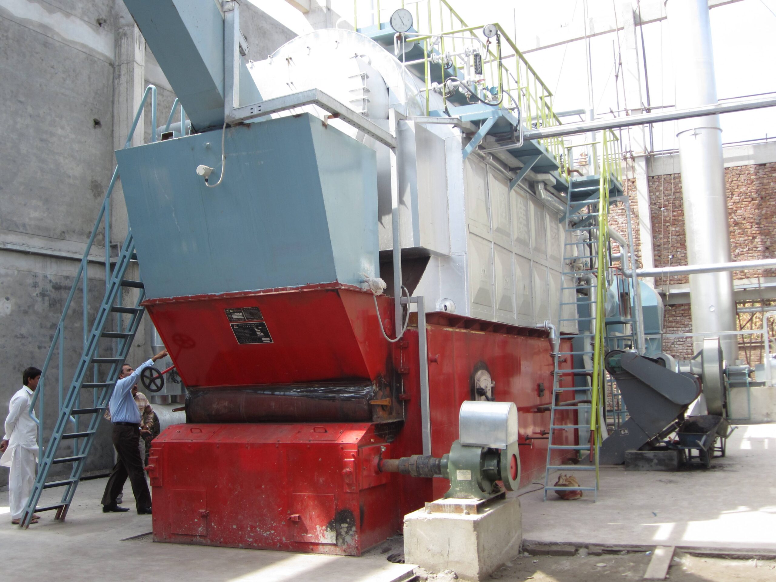
![Power Plant Boiler Furnace Section]
Prompt: Power plant boiler furnace section + cutaway diagram showing flame, water walls, and combustion process + large-scale industrial setting + realistic technical rendering + dynamic and energetic mood + high-temperature lighting effects
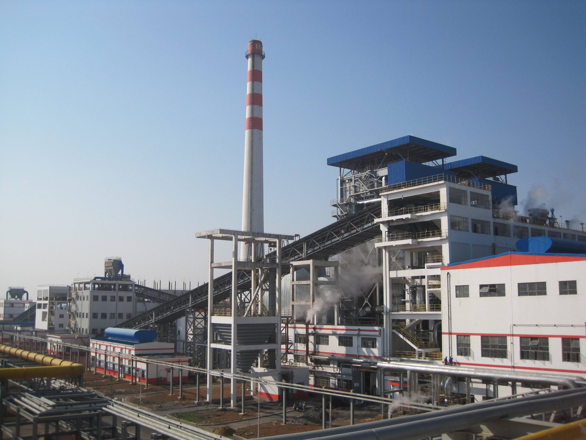
In thermal power generation, the furnace is the heart of the boiler system—the location where the fuel’s chemical energy is first transformed into usable heat. If the furnace is poorly designed, mismanaged, or damaged, combustion becomes inefficient, fuel is wasted, emissions increase, and the boiler may suffer critical failures. As such, the performance of the furnace has a direct impact on a power plant’s thermal efficiency, operational stability, and environmental compliance. To maintain reliable steam production, consistent fuel combustion, and safety, understanding the furnace’s function is essential.
The furnace in a power plant boiler serves as the primary combustion chamber where fuel—such as coal, gas, oil, or biomass—is burned to release thermal energy. This heat is transferred to surrounding water walls, converting water into high-pressure steam. The furnace plays a vital role in flame stabilization, heat generation, emission control, and energy transfer efficiency, forming the foundation of the entire power generation cycle.
Whether in pulverized coal-fired units, circulating fluidized bed (CFB) boilers, or gas-fired systems, the furnace must be optimized to support high combustion efficiency, low emissions, and structural integrity under extreme conditions.
Functional Role of the Furnace in the Boiler System
| Function | Description |
|---|---|
| Combustion of Fuel | Provides the controlled environment where fuel is ignited and burned |
| Heat Generation | Produces the thermal energy needed to generate steam |
| Radiant Heat Transfer | Transfers energy through radiation to water-cooled furnace walls |
| Flame Stabilization | Maintains steady flame shape and location for safe and efficient combustion |
| Emission Formation Control | Impacts formation of pollutants like NOx, CO, and unburned carbon |
The furnace is lined with membrane water walls made of steel tubes, which absorb most of the radiant heat and convert water into steam. The size, shape, and design parameters of the furnace directly influence how well this heat transfer occurs.
Types of Furnaces in Power Plant Boilers
| Furnace Type | Description | Common Fuel Type |
|---|---|---|
| Pulverized Fuel Furnace | Burns finely ground coal with tangential or wall-mounted burners | Coal |
| Fluidized Bed Furnace | Uses air to suspend fuel particles in a turbulent bed | Biomass, coal, waste |
| Oil/Gas-Fired Furnace | Burns atomized fuel in a flame envelope | Natural gas, diesel |
| Stoker Furnace | Uses mechanical grates for solid fuel combustion | Wood, coal, waste biomass |
Each type is engineered based on fuel characteristics, heat demand, and plant load flexibility.
Thermal and Combustion Dynamics
The furnace must provide three essential elements for combustion, often known as the “fire triangle”:
Fuel – Solid, liquid, or gaseous
Oxygen (from air) – Supplied by forced or induced draft fans
Heat (Ignition Source) – Ignition via burners or pilot flame
Key parameters that influence furnace performance:
| Parameter | Optimal Range | Effect on Operation |
|---|---|---|
| Combustion Temp | 1,200–1,500°C (coal/gas/oil) | Affects flame stability and NOx formation |
| Residence Time | 1–2 seconds | Determines completeness of combustion |
| Excess Air | 10–20% above stoichiometric | Ensures complete combustion but lowers efficiency if too high |
| Furnace Exit Gas Temp (FEGT) | 900–1,200°C | Impacts heat transfer and slagging risk |
Heat Transfer and Energy Conversion Role
The furnace contributes approximately 40–50% of the total heat absorbed in a boiler. This occurs primarily via radiation, as opposed to the convection-dominated zones downstream (e.g., superheaters and economizers).
| Heat Transfer Zone | Mechanism | Contribution (%) |
|---|---|---|
| Furnace (Water Walls) | Radiation | 45–50% |
| Superheater, Reheater | Convection | 20–30% |
| Economizer | Convection | 10–15% |
| Air Preheater | Convection | 5–10% |
Water circulating in the furnace walls absorbs heat and turns into saturated steam. In once-through and high-pressure boilers, this steam goes directly to the superheater.
Emissions Control via Furnace Design
The furnace design can significantly reduce pollutant formation at the source. For example:
Low-NOx burners and staged combustion control the flame temperature and oxygen availability to reduce nitrogen oxide formation.
Flue Gas Recirculation (FGR) lowers flame temperature and dilutes combustion gases.
Sorbent injection inside fluidized bed furnaces captures SO₂ during combustion.
| Pollutant | Formation Zone | Mitigation Strategy |
|---|---|---|
| NOx | High-temperature flame | Staged air, low-NOx burners, FGR |
| CO | Incomplete combustion | Proper air-fuel ratio and residence time |
| SO₂ | From sulfur in fuel | Limestone injection or post-treatment |
| PM | Unburned particles | Better burnout and furnace exit controls |
Design Considerations and Best Practices
A well-designed furnace must address the following:
| Design Factor | Importance |
|---|---|
| Furnace Volume | Must allow sufficient residence time for combustion |
| Height-to-Width Ratio | Affects heat flux and flame path |
| Water Wall Surface Area | Dictates heat absorption capacity |
| Slagging and Fouling Control | Prevents heat transfer losses and corrosion |
| Material Selection | Handles high temperatures and corrosive gases |
In CFB boilers, the furnace is typically taller and narrower to allow for vertical fluidization and particle recirculation, which further enhances combustion efficiency and reduces unburned carbon.
Monitoring and Control of Furnace Operations
Modern power plants use control systems to manage furnace conditions via:
Bed/furnace temperature sensors
Flame scanners for burner operation
Pressure differential monitoring
Continuous Emission Monitoring Systems (CEMS)
Furnace Exit Gas Temperature (FEGT) thermocouples
These tools feed data into DCS (Distributed Control Systems) to adjust:
Burner firing rate
Air/fuel ratio
Feedwater flow
Sootblower operation
Summary: Furnace as the Energy Core
| Role | Function |
|---|---|
| Combustion Chamber | Converts fuel to heat energy |
| Radiant Heat Transfer Zone | Transfers heat to water walls to generate steam |
| Flame Stabilization | Maintains safe and efficient combustion |
| Emission Formation Site | Determines NOx, CO, SOx levels based on design and control |
| Steam Generation Source | Supplies energy for turbine-driven power generation |
In short, the furnace is where the transformation of fuel into usable thermal energy begins. Its performance governs not just steam output, but the entire thermal efficiency and environmental footprint of the power plant. With advances in design, materials, and automated control, modern furnace systems continue to be the centerpiece of reliable and sustainable power production.
How do water walls contribute to steam generation and heat absorption?
![Water Wall Tubes in a Power Plant Boiler]
Prompt: Industrial water wall tubes inside a boiler furnace + high-resolution cutaway diagram + showing radiant heat transfer to water-filled steel tubes + flames and combustion zone in background + large-scale power plant setting + thermal-focused atmosphere + intense warm lighting
In the heart of every power plant boiler, the efficient conversion of fuel energy into steam begins with radiant heat transfer. If this step is compromised—through inadequate heat absorption or poor circulation—the boiler’s efficiency suffers, steam output drops, and risk of overheating or failure increases. Water walls, also known as furnace walls or membrane walls, are the primary surfaces responsible for absorbing the radiant heat from combustion inside the furnace. These vertical tube panels line the boiler’s interior, playing a vital role in energy capture and steam generation.
Water walls in a boiler are heat-absorbing tube panels that form the internal walls of the furnace, capturing radiant energy emitted by fuel combustion and converting feedwater inside them into steam or high-temperature water. Their function is critical for efficient thermal absorption, maintaining uniform furnace temperature, initiating the water-to-steam phase change, and supporting overall boiler efficiency and safe operation.
Understanding the mechanics of how water walls work is essential for engineers, plant operators, and maintenance teams to optimize steam generation and protect boiler integrity in high-temperature environments.
Structural and Thermal Function of Water Walls
Water walls are comprised of vertical steel tubes that are either:
Bare tubes (in older designs), or
Membrane walls: Tubes joined by steel membranes welded in between to form gas-tight furnace walls (modern design standard)
| Feature | Function |
|---|---|
| Water-Cooled Surface | Absorbs radiant energy from combustion flame |
| Heat Exchange Medium | Water or steam-water mixture flows inside the tubes |
| Steam Generation Start Point | Water begins phase change due to intense heat |
| Structural Support | Forms the pressure boundary and furnace enclosure |
These walls form the boundary of the furnace and are directly exposed to the intense radiation emitted by burning fuel (temperatures often exceeding 1,200–1,500°C).
Heat Transfer Mechanism
Radiant heat transfer from the flame to the water wall tubes follows Stefan-Boltzmann law, where radiation increases exponentially with temperature. In water walls:
Radiation is the dominant heat transfer mode (not convection)
Heat flux can range from 150–300 kW/m² depending on furnace size and fuel
Water or steam-water mixture inside the tubes carries the heat away to the steam drum or separators
Heat Absorption Process
Water enters the water wall tubes from the bottom headers (cold-end).
As water ascends the tube, radiant heat is absorbed, and temperature rises.
At certain point (saturation temp), phase change begins—water starts turning to steam.
Mixture of water and steam exits the top header and goes to the steam drum for separation.
| Region of Water Wall Tube | Thermal State of Water |
|---|---|
| Bottom | Subcooled liquid |
| Middle | Saturated boiling mixture |
| Top | Steam-water mixture |
Contribution to Steam Generation
Water walls are responsible for 35% to 50% of the total steam generation in a large utility boiler, particularly due to:
High heat absorption area: Vertical panels line four furnace walls
Long exposure time: Tall furnaces increase residence time for heat exchange
Optimized flow rate: Designed to match mass flow and boiling characteristics
Design Parameters and Operating Conditions
| Parameter | Typical Range |
|---|---|
| Tube Diameter | 38–76 mm (outer) |
| Tube Material | Carbon steel, alloy steel |
| Wall Thickness | 3–6 mm |
| Pressure Rating | Up to 300 bar |
| Water Flow Velocity | 1–3 m/s |
| Heat Flux Exposure | 150–300 kW/m² |
| Wall Temperature | 350–500°C (outer wall) |
In high-pressure, once-through boilers (like in supercritical power plants), water walls serve as evaporator circuits, and the entire steam generation process begins and completes inside these tubes before entering the superheater.
Types of Water Wall Designs
| Type | Characteristics | Applications |
|---|---|---|
| Bare Tube Walls | Older design, gaps between tubes, less efficient | Low-pressure boilers |
| Membrane Walls | Tubes joined by metal fins/membranes, gas-tight enclosure | Modern utility & industrial boilers |
| Tangentially Fired Furnace Walls | Designed for corner-firing flame patterns | Pulverized coal units |
| Spiral and Vertical Panels | For once-through designs; promote stable flow | Supercritical boilers |
Performance Impact: Efficiency and Safety
A. Efficiency Contributions
Absorbs up to 50% of total furnace heat input
Reduces heat load on superheaters and economizers
Improves boiler thermal efficiency by preventing energy loss to refractory walls
B. Safety Enhancements
Prevents furnace wall overheating and material failure
Ensures uniform heat absorption to avoid hot spots
Forms gas-tight barrier to contain combustion gases and protect the boiler casing
Monitoring and Maintenance Best Practices
| Action | Purpose |
|---|---|
| Thermal imaging scans | Detect hot spots or tube overheating |
| Thickness testing (UT) | Monitor for tube erosion or corrosion |
| Inspection of headers and welds | Identify cracking or joint degradation |
| Boiler blowdown and water chemistry control | Prevent internal scaling/fouling |
| Proper circulation design | Prevents tube dry-out and heat flux imbalance |
Inadequate water flow or poor thermal transfer can lead to boiler tube failure, steam blanketing, and dangerous thermal stresses, which is why regular monitoring is essential.
Summary of Water Wall Functions
| Function Area | Contribution of Water Walls |
|---|---|
| Steam Generation | Initiates phase change of feedwater via radiant heat |
| Thermal Absorption | Captures majority of radiant furnace energy |
| Pressure Containment | Forms part of the boiler pressure boundary |
| Combustion Enclosure | Maintains furnace geometry and isolates heat |
| Safety Assurance | Prevents flame impingement on boiler casing |
Water walls are not just passive components—they are active, high-performance elements that define the boiler’s ability to efficiently and safely produce steam under extreme conditions. Their proper design, operation, and maintenance are critical to modern thermal power generation.
What are superheaters and reheaters, and how do they improve steam quality?
![Superheaters and Reheaters in Power Plant Boilers]
Prompt: Industrial superheaters and reheaters inside a power plant boiler + high-temperature steam tubes with radiant and convective zones + labeled cross-section showing steam flow + realistic thermal engineering setting + high-tech atmosphere + glowing orange lighting
In thermal power generation, the quality and efficiency of steam directly impact the performance of turbines, overall plant output, and fuel economy. Saturated steam generated in the boiler drum contains moisture, which can cause erosion, inefficiency, and mechanical damage in turbine blades. To overcome this, superheaters and reheaters are integrated into modern boiler systems. Without them, steam turbines would operate with lower thermal efficiency and require more frequent maintenance. These heat exchanger components raise steam temperature well above saturation, significantly improving energy transfer, system reliability, and efficiency.
Superheaters and reheaters are heat exchanger components in power plant boilers that elevate the temperature of steam beyond its saturation point without increasing pressure. Superheaters convert saturated steam into dry or superheated steam before it enters the high-pressure turbine, while reheaters reheat partially expanded steam exiting the high-pressure turbine for reuse in the intermediate or low-pressure turbine stages. Together, they improve steam quality, reduce turbine moisture content, increase cycle efficiency, and enable higher thermal outputs.
Both components are crucial for plants using Rankine or combined-cycle systems, particularly in high-capacity steam turbines where even small improvements in steam quality can lead to large gains in power generation efficiency and durability.
Superheaters: Structure, Function, and Role
Superheaters are positioned in the convective and radiant zones of the boiler and are made up of tube bundles that absorb heat from flue gases to increase steam temperature. The steam entering a superheater is saturated (wet) steam, and it exits as superheated (dry) steam, with a temperature up to 540°C or higher.
| Parameter | Typical Range |
|---|---|
| Inlet Steam Temp | ~300–350°C (saturated steam) |
| Outlet Steam Temp | 500–600°C (superheated) |
| Steam Pressure | 100–250 bar (depending on boiler) |
| Heat Source | Radiant + convective flue gas |
| Location | Upper furnace, flue gas pass |
Benefits of Superheating:
Increases turbine efficiency by raising enthalpy drop across stages
Prevents blade erosion by eliminating moisture
Allows higher power output from same mass flow
Supports dry expansion, improving turbine life
Types of Superheaters
| Type | Description | Application |
|---|---|---|
| Radiant Superheater | Absorbs heat directly from furnace radiation | High-temperature boost zone |
| Convective Superheater | Located in flue gas path, uses convection heating | Secondary superheating or control |
| Platen Superheater | Positioned near the upper furnace, facing the flame | Handles large heat loads |
| Pendant/Horizontal | Hung in convection path for additional heat pickup | Stabilizes final outlet temperature |
Reheaters: Function and Thermodynamic Impact
After high-pressure steam expands in the high-pressure (HP) turbine, it loses energy and becomes partially wet. This partially expanded steam is routed back into the reheater, where it is reheated before being sent into the intermediate-pressure (IP) or low-pressure (LP) turbine for further expansion.
| Reheater Role | Description |
|---|---|
| Inlet Steam Quality | Partially wet, ~300–400°C |
| Outlet Steam Temperature | Reheated to ~500–560°C |
| Cycle Integration | Between HP and IP/LP turbine stages |
| Main Benefit | Maintains dryness of steam throughout turbine path |
Advantages of Reheating:
Avoids moisture condensation in turbine LP stages
Enhances thermodynamic efficiency of Rankine cycle
Reduces blade corrosion and wear
Enables multiple expansion stages for higher output
Performance Improvement via Superheaters and Reheaters
| Aspect | Saturated Steam Cycle | Superheated/Reheated Cycle |
|---|---|---|
| Thermal Efficiency | ~30–35% | ~38–45% |
| Steam Turbine Damage | Higher risk (due to moisture) | Significantly reduced |
| Specific Steam Consumption | Higher (~4.5 kg/kWh) | Lower (~3.5 kg/kWh) |
| Enthalpy Drop | Limited | Maximized (better energy extraction) |
| Boiler Output Quality | Wet steam | Dry, high-energy steam |
Thermodynamic Visualization: T-s Diagram
T (Temperature)
|
|               _______
|             /        \
|            /          \
|        A–>B            C–>D
|       (Superheat)      (Reheat)
|     /                      \
|    /                        \
|___/                          \_________ S (Entropy)
A–B: Superheating of saturated steam
C–D: Reheating after partial expansion
This improves the Mean Temperature of Heat Addition, increasing cycle efficiency.
Material and Design Considerations
Because of the extremely high temperatures and pressures, superheaters and reheaters must be built from high-grade materials:
| Component | Material Examples | Purpose |
|---|---|---|
| Tubes | SA213 T91, Inconel, austenitic steel | Resist creep, corrosion, and stress |
| Supports & Hangers | Alloy steel with expansion features | Handle thermal movement |
| Headers | Forged steel | Withstand high pressure/temperature |
Proper thermal expansion management is essential. These components expand several centimeters under load and must be allowed to move without causing stress fractures.
Control and Monitoring in Operation
| Control Element | Role |
|---|---|
| Attemperators (Desuperheaters) | Regulate steam temperature by spraying water |
| Thermocouples/RTDs | Monitor tube wall and steam temps |
| Flow Measurement Devices | Ensure uniform steam distribution |
| Bypass Systems | Divert flow during startup or maintenance |
Common Challenges and Mitigations
| Issue | Solution/Prevention |
|---|---|
| Overheating or tube failure | Accurate temp control, proper water chemistry |
| Thermal stress cracking | Expansion joints, controlled ramp-up |
| Steam temperature fluctuation | Multi-stage attemperation and feedback |
Summary: How They Improve Steam Quality
| Component | Function | Impact on Performance |
|---|---|---|
| Superheater | Increases steam temperature above saturation | Higher turbine efficiency, dry steam |
| Reheater | Reheats partially expanded steam | Extends expansion process, prevents moisture |
| Combined Effect | Improves thermodynamic efficiency | Reduces fuel use, emissions, and turbine wear |
In conclusion, superheaters and reheaters are fundamental components of high-performance power plant boilers. They upgrade raw steam into a powerful, dry, and efficient medium capable of delivering maximum energy to turbines with minimal wear. Without them, modern thermal power generation would be significantly less efficient and far more costly to maintain.
How does the economizer enhance thermal efficiency in a power plant boiler?
![Boiler Economizer Heat Recovery System]
Prompt: Economizer heat exchanger in a power plant boiler + cross-sectional industrial diagram + showing feedwater flowing through finned tubes and flue gas stream + steam generator background + technical environment + energy-efficient mood + warm industrial lighting
In thermal power plants, maximizing energy extraction from every kilogram of fuel is vital to improve efficiency and reduce emissions. A significant portion of energy from fuel combustion is lost through high-temperature flue gases. If not captured, this waste heat reduces overall boiler efficiency and increases fuel consumption. This is where the economizer comes into play. Positioned in the flue gas path, the economizer recovers sensible heat and uses it to preheat boiler feedwater—leading to substantial thermal savings and improved steam generation performance.
An economizer enhances the thermal efficiency of a power plant boiler by recovering residual heat from flue gases and transferring it to the incoming feedwater before it enters the boiler drum or evaporator section. This preheating process reduces the energy required to convert water into steam, thereby decreasing fuel consumption, lowering stack temperature, improving boiler responsiveness, and enhancing overall plant efficiency by 3–8%.
Economizers are essential components in coal, gas, oil, and biomass-fired boilers and are a proven solution for reducing operational costs and improving environmental compliance.
What Is an Economizer?
An economizer is a type of heat exchanger installed in the boiler flue gas duct after the combustion chamber but before the air preheater or stack. It consists of finned or bare tubes that carry boiler feedwater. As flue gases pass over the tube surface, their heat is transferred to the water inside.
| Component | Function |
|---|---|
| Tubes (finned or smooth) | Carry feedwater and absorb heat from flue gas |
| Headers | Distribute and collect water uniformly |
| Casing/Ducting | Ensures controlled flue gas flow over heat transfer area |
| Drain & Vent System | Removes trapped air or condensate from water circuits |
Economizers operate on the counterflow principle, where water and flue gases flow in opposite directions to maximize temperature gradient and heat transfer.
How the Economizer Improves Thermal Efficiency
The primary role of the economizer is to raise feedwater temperature before it enters the boiler drum or evaporator. This reduces the required fuel heat input for steam generation.
| Efficiency Enhancement Mechanism | Result |
|---|---|
| Feedwater Preheating | Less energy needed in furnace to reach boiling point |
| Reduced Flue Gas Temperature | Minimizes heat loss through stack |
| Improved Heat Utilization | Recovers ~5–15% of energy lost in flue gas |
| Lower Fuel Consumption | Up to 10% fuel savings depending on load/fuel |
| Shorter Startup Times | Quicker approach to boiling conditions |
Performance Parameters of Economizers
| Parameter | Typical Range |
|---|---|
| Flue Gas Inlet Temp | 300–450°C |
| Flue Gas Exit Temp | 150–250°C |
| Feedwater Inlet Temp | 80–120°C |
| Feedwater Outlet Temp | 150–200°C |
| Heat Transfer Efficiency | 70–85% |
| Efficiency Gain (Overall Boiler) | 3–8% |
Sample Energy Savings from Economizer Use
| Plant Size (MW) | Economizer Energy Recovery (kCal/hr) | Annual Fuel Savings (tons) |
|---|---|---|
| 50 MW | ~25 million | ~3,500 |
| 100 MW | ~50 million | ~7,200 |
| 300 MW | ~150 million | ~22,000 |
Types of Economizers
| Type | Description | Application |
|---|---|---|
| Bare Tube Economizer | Simple design with plain tubes; lower surface area | Low to medium-duty boilers |
| Finned Tube Economizer | Enhanced surface area using fins around tubes | High-pressure, large boilers |
| Coil Economizer | Compact design for tight spaces | Package boilers |
| Condensing Economizer | Recovers latent heat from flue gas moisture (low temp) | Natural gas and clean-burning fuels |
Economizer in the Boiler Heat Path
Boiler Flow Path:
Combustion → Furnace (Radiant Heat) → Superheater → Reheater → Economizer → Air Preheater → Stack
                                                             ↑
                                                      Feedwater Flow
The economizer is the last step in the heat exchange path before the flue gas exits.
It is also the first point of heat gain for the feedwater entering the boiler.
Comparison: With vs Without Economizer
| Parameter | Without Economizer | With Economizer |
|---|---|---|
| Feedwater Inlet Temp | 60–90°C | 150–200°C |
| Flue Gas Exit Temp | >300°C | ~200°C |
| Fuel Consumption | Higher | Reduced by 5–10% |
| Boiler Thermal Efficiency | 78–82% | 85–88% |
| Stack Heat Loss | Significant | Minimized |
Materials and Design Considerations
| Component | Common Material | Reason |
|---|---|---|
| Tubes | Carbon steel, alloy steel | High-temperature corrosion resistance |
| Fins | Stainless steel, aluminum | High surface area, thermal conductivity |
| Support Frames | Mild steel with coatings | Structural durability |
Economizers must also be designed to handle thermal expansion, soot accumulation, and acid dew point corrosion (especially in sulfur-containing fuels). Proper drainage and insulation are critical for long-term performance.
Operational Challenges and Maintenance
| Challenge | Prevention / Mitigation |
|---|---|
| Soot and ash fouling | Sootblowers or acoustic cleaning |
| Tube leakage or cracking | Proper water chemistry, inspection routines |
| Acid condensation | Maintain flue gas temp above acid dew point (~150°C) |
| Flow imbalance | Uniform header design and CFD modeling |
Routine inspections and thermal imaging can help detect early signs of tube fouling or heat transfer degradation.
Integration with Boiler Control Systems
Modern economizers are monitored and controlled via DCS (Distributed Control Systems) and equipped with:
Temperature sensors (inlet/outlet water and gas)
Pressure transmitters
Flow meters
Bypass dampers (for load matching and emergency operation)
This integration enables dynamic optimization of energy recovery and protects the boiler against thermal imbalances.
Summary: Key Benefits of Economizers
| Benefit | Description |
|---|---|
| Fuel Efficiency | Reduces the need for fuel by recovering heat |
| Boiler Efficiency Boost | Increases total thermal efficiency by 3–8% |
| Emission Reduction | Less fuel burned = fewer CO₂, SOx, and NOx emissions |
| Water Preheating | Improves heat absorption and reduces thermal shock |
| Extended Boiler Life | Stabilizes boiler operation and reduces stress on components |
The economizer is not just a supplementary device—it is a strategic component that bridges heat recovery with feedwater preconditioning. For any power plant aiming to enhance efficiency and reduce costs, an optimized economizer system is a critical investment.
What is the function of the air preheater in the boiler system?
![Air Preheater in Industrial Boiler System]
Prompt: Air preheater system in a thermal power plant boiler + cross-sectional diagram showing flue gas heating combustion air + rotary and tubular heat exchanger elements + clean industrial setting with labeled ducting and fans + high-efficiency mood + bright technical lighting
In a power plant boiler, maximizing combustion efficiency is crucial to optimize fuel use, reduce emissions, and boost overall thermal performance. However, if the combustion air enters the furnace at ambient or low temperatures, more fuel is needed to initiate and sustain the desired heat output. This not only increases operational costs but also causes more pollutants to be formed. The air preheater (APH) addresses this by utilizing residual heat from flue gases to preheat the incoming combustion air—resulting in improved efficiency, fuel savings, and reduced stack temperatures.
The air preheater in a boiler system functions as a heat recovery device that transfers residual heat from the flue gases to the incoming combustion air. By increasing the temperature of the air before it enters the furnace, the air preheater enhances fuel combustion efficiency, reduces fuel consumption, improves boiler thermal efficiency, and lowers exhaust gas temperature. It plays a vital role in boosting the overall energy balance and emission control of the boiler.
Let’s explore how the air preheater works, the types used in power plants, and its impact on boiler performance and environmental compliance.
How the Air Preheater Works
Air preheaters are installed at the exit of the economizer and before the flue gas stack, where the flue gas is still hot. Combustion air from the atmosphere is drawn in by forced draft (FD) fans and directed through the air preheater, where it absorbs heat from the outgoing flue gas.
| Flow Path | Description |
|---|---|
| Flue Gas Side | Enters air preheater after economizer at ~250–350°C |
| Air Side | Ambient air enters and exits at ~120–200°C |
| Heat Transfer | Conducted through tubes or plates between gas and air streams |
This recovered heat reduces the fuel required to bring combustion air to ignition temperature, thus increasing combustion efficiency.
Types of Air Preheaters
| Type | Description | Common Application |
|---|---|---|
| Tubular Air Preheater | Consists of parallel tubes; flue gas outside, air inside or vice versa | Small to medium boilers |
| Rotary (Ljungström) Air Preheater | Rotating matrix absorbs heat from flue gas and releases it to air | Large utility boilers |
| Plate-Type Air Preheater | Stationary plates with alternating air and gas channels | Compact boilers, industrial systems |
Key Design Elements
| Component | Function |
|---|---|
| Heat Transfer Matrix | Provides surface area for air and gas heat exchange |
| Sector Plates | Segregate air and gas flows in rotary units |
| Bearings & Drives | Enable rotation and sealing in rotary systems |
| Dampers | Regulate airflow and prevent pressure imbalances |
Air Preheater Operating Parameters
| Parameter | Typical Range |
|---|---|
| Flue Gas Inlet Temp | 250–350°C |
| Flue Gas Exit Temp | 130–180°C |
| Air Inlet Temp | Ambient (~25–40°C) |
| Air Outlet Temp | 120–200°C |
| Heat Recovery Efficiency | 50–70% |
| Pressure Drop | 2–4 kPa (air side); 3–6 kPa (gas side) |
Thermal Efficiency Enhancement
The air preheater improves boiler efficiency in the following ways:
Preheating combustion air reduces fuel demand by lowering ignition lag.
Flue gas temperature reduction recovers waste heat that would otherwise be lost.
Improved flame temperature increases combustion completeness and reduces CO/NOx.
| Boiler Efficiency Metric | Without APH | With APH |
|---|---|---|
| Boiler Thermal Efficiency | 82–85% | 86–89% |
| Specific Fuel Consumption | Higher | Reduced |
| Stack Gas Losses | High | Lower |
| Startup Time | Longer | Shorter |
Air Preheater in Boiler Heat Path
Furnace → Superheater → Reheater → Economizer → Air Preheater → Flue Stack
                                    ↑
                             Combustion Air → FD Fan → Air Preheater → Furnace
The APH sits at the end of the flue gas path and at the start of the air path, acting as the final opportunity to recover energy before the gases are released.
Emission Reduction and Environmental Role
Preheated combustion air enables:
Higher combustion temperatures = better burnout and lower CO
Stable air-fuel ratios = reduced formation of NOx and unburned hydrocarbons
Lower excess air requirements = minimized thermal losses
Sample Emission Improvements
| Pollutant | Typical Reduction with APH |
|---|---|
| CO | 10–20% |
| NOx | 5–15% |
| SO₂ (indirect) | Slight reduction due to less fuel burned |
Challenges and Maintenance Considerations
| Challenge | Solution or Mitigation |
|---|---|
| Ash and dust fouling | Use sootblowers or rotary cleaning devices |
| Corrosion (acid dew point) | Maintain flue gas outlet temp >130°C |
| Air leakage (rotary APH) | Maintain seals and monitor differential pressures |
| Mechanical wear in rotary units | Schedule inspections and replace seals/segments |
Corrosion is particularly a risk when firing high-sulfur coal or biomass fuels that result in sulfuric acid condensation.
Monitoring and Integration
Modern APHs are equipped with:
Temperature sensors (inlet/outlet air and gas)
Pressure and flow meters
Seal leakage monitors (in rotary types)
Integration with DCS for combustion control optimization
Variable Frequency Drives (VFDs) on FD and ID fans allow dynamic control of air and gas flows to maintain optimal heat exchange.
Summary: Air Preheater’s Role in Boiler Performance
| Function Area | Contribution of Air Preheater |
|---|---|
| Fuel Efficiency | Recovers flue gas heat, reduces combustion fuel demand |
| Combustion Stability | Supplies warm air, supports complete fuel burn |
| Emission Control | Enables cleaner combustion with lower excess air |
| Thermal Efficiency | Increases boiler output with less energy input |
| System Integration | Works with economizer and furnace for full-cycle optimization |
The air preheater is more than just a supporting element—it is a critical energy recovery and efficiency component in any modern boiler system. Properly designed and maintained, it significantly enhances the sustainability and economic performance of thermal power generation.
How do control and emission systems optimize boiler performance and environmental compliance?
![Boiler Control and Emission Monitoring System in Industrial Plant]
Prompt: Boiler control and emission system integration + control panel with real-time data + stack emission monitoring equipment + digital interface with graphs and alerts + industrial boiler background + clean and efficient atmosphere + cool ambient lighting
In today’s power and industrial boiler systems, achieving high thermal efficiency alone is no longer sufficient. Regulatory pressure on air pollution, rising energy costs, and sustainability goals demand advanced solutions for both performance optimization and environmental compliance. Traditional boiler operations, when left to manual or isolated controls, often result in inefficient combustion, excessive emissions, fuel waste, and system failures. Modern control and emission systems work together to solve these issues—delivering automated precision, safety, and compliance with national and international environmental standards.
Control and emission systems in boiler operations function synergistically to optimize combustion, reduce fuel consumption, improve steam quality, and monitor/limit air pollutant emissions. Automated control systems use real-time sensor data and advanced logic to manage fuel-air ratios, temperature, pressure, and flow rates, while emission systems continuously track pollutants like NOx, SO₂, CO, and particulates, adjusting combustion and sorbent dosing to stay within permitted thresholds. This integrated approach ensures maximum thermal performance with minimal environmental impact.
This article explores how these systems function, their components, and the measurable benefits they deliver to both operational and environmental objectives.
Core Functions of Boiler Control and Emission Systems
| System Function | Description |
|---|---|
| Combustion Control | Maintains ideal air-fuel ratio for efficient and complete combustion |
| Feedwater & Steam Control | Regulates pressure, drum level, and steam temperature |
| Oxygen Trim Control | Adjusts air input based on excess O₂ in flue gas |
| Emission Monitoring (CEMS) | Continuously tracks NOx, SO₂, CO, O₂, and particulate levels |
| Flue Gas Recirculation | Reuses exhaust gases to reduce flame temperature and NOx formation |
| Sorbent Injection Systems | Doses limestone or activated carbon to neutralize SO₂ and mercury |
Boiler Control Systems: Architecture and Optimization
Modern boilers rely on Distributed Control Systems (DCS) or Programmable Logic Controllers (PLC) to process signals from dozens or hundreds of sensors and execute coordinated control actions.
Key Subsystems:
| Subsystem | Controlled Parameters |
|---|---|
| Combustion Management | Fuel feed, burner modulation, air dampers |
| Drum Level Control | Feedwater flow, steam outlet, drum level |
| Steam Temperature Control | Attemperator sprays, superheater bypass |
| Airflow Control | Forced and induced draft fans, dampers |
| Load-Following Control | Matches boiler output to turbine or process demand |
Advanced PID loops, fuzzy logic, and AI-based models are often integrated to ensure dynamic stability during transient loads.
Real-Time Performance Optimization
| Parameter | Optimization Method | Benefit |
|---|---|---|
| O₂ in Flue Gas | Oxygen trim control | Prevents excess air, improves combustion |
| NOx Formation | Staged combustion, low-NOx burners | Limits thermal NOx below regulatory limits |
| Steam Temperature | Feedforward control, attemperation | Protects turbine, improves steam quality |
| Bed Pressure (CFB) | Controls fluidization rate | Maintains stable combustion in CFB systems |
| Fuel Moisture Fluctuation | Adaptive combustion logic | Prevents flame instability, reduces CO |
Emission Monitoring and Control Technologies
Regulatory agencies require Continuous Emissions Monitoring Systems (CEMS) for pollutants. These devices are typically installed in the stack and linked to the plant control network.
| Pollutant | Source in Boiler | Control Method |
|---|---|---|
| NOx | High-temperature combustion | Staged air, FGR, Low-NOx burners, SNCR/SCR |
| SO₂ | Sulfur in fuel | Limestone injection, wet or dry scrubbers |
| CO | Incomplete combustion | Improved fuel-air mixing, O₂ trim |
| Particulate Matter | Fly ash, unburned carbon | Cyclones, ESPs, bag filters |
| Hg (Mercury) | Coal and waste combustion | Activated carbon injection (ACI) |
CEMS Components:
| Device Type | Function |
|---|---|
| Gas Analyzer | Measures NOx, SO₂, CO, CO₂, O₂ concentrations |
| Opacity Monitor | Estimates particulate concentration |
| Data Acquisition System (DAS) | Logs, stores, and reports emissions data |
| Calibration Systems | Ensure sensor accuracy per EPA/EN standards |
Efficiency Gains from Integrated Systems
| Metric | Traditional Control | Modern Control & Emissions System |
|---|---|---|
| Boiler Efficiency | 80–85% | 88–92% |
| Specific Fuel Consumption | Higher | Reduced by 5–10% |
| Steam Quality Stability | Variable | Highly stable |
| CO and NOx Emissions | Fluctuating | Reduced by 30–60% |
| Operator Intervention | Frequent | Minimal (automatic optimization) |
Case Study: Coal-Fired Boiler with Integrated Control and CEMS
A 200 MW coal-fired power plant in Eastern Europe upgraded its boiler control with AI-enhanced combustion logic and CEMS-linked emission feedback.
Results:
Fuel consumption reduced by 6.8%
NOx emissions decreased from 280 to 115 mg/Nm³
Plant availability improved from 94.3% to 97.1%
SO₂ capture improved via dynamic limestone injection feedback
This transformation brought the plant in line with EU Industrial Emissions Directive (IED) standards and significantly reduced operational costs.
System Integration Best Practices
| Practice | Purpose |
|---|---|
| Use of predictive analytics | Detect performance decline before failures occur |
| Regular calibration of CEMS | Maintain accuracy of emissions data |
| Control loop tuning | Minimize lag and overshoot in process response |
| Cybersecurity measures | Protect PLC/DCS from tampering or downtime |
| Staff training on HMI interfaces | Ensure proper interpretation and override management |
Summary: Why These Systems Matter
| Optimization Area | Contribution of Control & Emission Systems |
|---|---|
| Efficiency | Improved combustion accuracy, fuel savings |
| Reliability | Reduced manual intervention, increased operational uptime |
| Compliance | Real-time emission tracking and regulation adherence |
| Flexibility | Supports variable fuel quality and load conditions |
| Sustainability | Enables cleaner combustion and lower carbon footprint |
In conclusion, control and emission systems form the intelligent backbone of modern boiler operations. They not only elevate efficiency and process control but also make regulatory compliance proactive, verifiable, and cost-effective. As emission standards tighten and energy demands increase, these systems will continue to be indispensable for sustainable boiler and power plant performance.
🔍 Conclusion
Power plant boilers are complex, high-performance systems designed to generate large volumes of high-pressure, high-temperature steam for electricity production. Each component—from the combustion chamber to the air preheater—plays a vital role in ensuring efficient, clean, and stable operation. A detailed understanding of these key parts empowers plant operators and engineers to optimize energy efficiency, extend equipment life, and ensure compliance with environmental regulations.
📞 Contact Us
💡 Need technical support or custom solutions for your power plant boiler? Our engineering team offers expert guidance on design, retrofitting, performance optimization, and compliance.
🔹 Contact us today to elevate your power generation system with trusted boiler technology! ⚡🔥
FAQ
What are the core components of a power plant boiler?
A power plant boiler includes critical components such as the furnace, steam drum, water walls, superheater, reheater, economizer, and air preheater, all working together to generate high-pressure steam.
What is the role of the furnace in a power plant boiler?
The furnace is where fuel combustion occurs, generating heat to convert water into steam in the boiler tubes lining the furnace walls.
What is a steam drum and why is it important?
The steam drum separates steam from water in the boiler system. It maintains pressure and ensures only dry steam is sent to the turbine for power generation.
What function does the superheater serve?
The superheater increases the temperature of saturated steam from the steam drum, producing high-temperature, high-pressure steam for improved turbine efficiency.
How do the economizer and air preheater improve boiler efficiency?
The economizer recovers heat from flue gases to preheat feedwater, while the air preheater warms incoming combustion air, both enhancing overall thermal efficiency.
References
Power Plant Boiler Systems Overview – https://www.energy.gov
Boiler Components and Operation – https://www.sciencedirect.com
Furnace Design in Power Boilers – https://www.researchgate.net
Steam Drum Function and Importance – https://www.epa.gov
Role of Superheaters in Boilers – https://www.bioenergyconsult.com
How Economizers Work in Boilers – https://www.mdpi.com
Air Preheater Technology – https://www.energysavingtrust.org.uk
Steam Generation for Power Plants – https://www.iea.org
Power Boiler Maintenance Best Practices – https://www.automation.com
Steam Cycle Efficiency in Power Plants – https://www.sciencedirect.com
