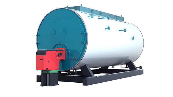
Industrial gas-fired boilers are widely adopted in manufacturing, processing, and energy sectors for their high thermal efficiency, cleaner combustion, and cost-effectiveness. However, without a clear understanding of the key components, businesses may face challenges such as incomplete combustion, system failures, and inefficient fuel usage. These issues can lead to higher operating costs and non-compliance with emission standards. Knowing the core components is essential for reliable operation, safety, and maximum efficiency.
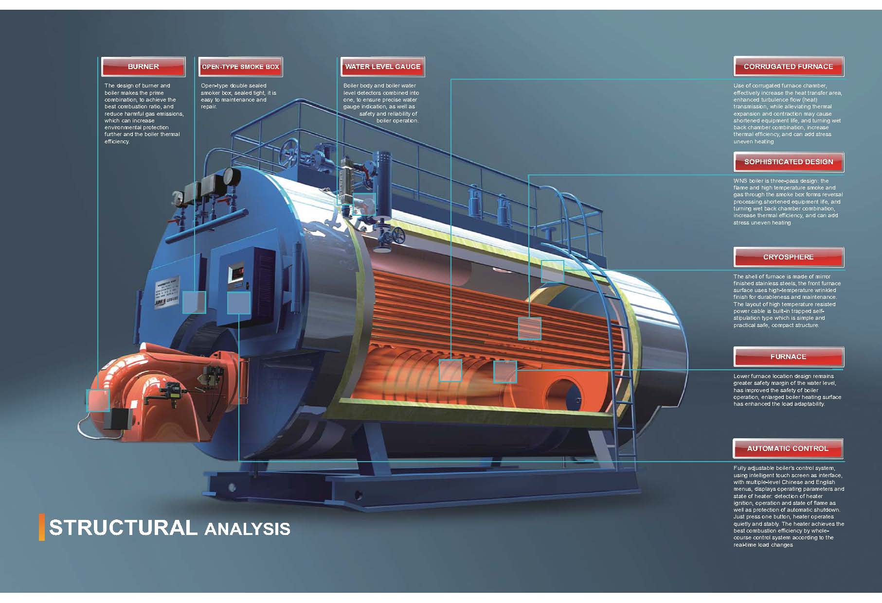
The key components of an industrial gas-fired boiler include the gas burner, combustion chamber, heat exchanger, fuel supply system, air and flue gas handling system, and control system. Each part is vital in achieving efficient gas combustion, optimal heat transfer, and emission control. Advanced gas-fired boilers are equipped with sophisticated monitoring and automation systems to ensure safe and efficient operation.
Understanding how these components function individually and as a system is essential for ensuring reliable performance, energy savings, and long-term operational success.
What Is the Function of the Gas Burner in an Industrial Gas-Fired Boiler?
In any industrial gas-fired boiler, one of the most critical elements for efficient and stable performance is the gas burner. If the burner malfunctions or is poorly designed, it can lead to incomplete combustion, excessive fuel consumption, emissions violations, and even dangerous explosions. For operators, engineers, and facility managers, understanding the true role and function of the gas burner is essential to ensuring optimal boiler operation, energy efficiency, and compliance with environmental standards.
The gas burner in an industrial gas-fired boiler is responsible for mixing the fuel gas with combustion air in precise proportions and igniting the mixture to produce a stable, controlled flame inside the combustion chamber. This process initiates the transfer of heat energy to the water or steam system, ensuring efficient fuel use, complete combustion, minimal emissions, and safe boiler operation.
To truly appreciate the function and impact of a gas burner, one must look beyond its ignition role. This article explains how it supports thermal efficiency, reduces environmental risks, and integrates with automation for advanced control.
How the Gas Burner Works in an Industrial Boiler
The gas burner acts as the core ignition and combustion interface between the boiler system and the fuel source. It operates in several coordinated stages:
1. Fuel-Air Mixing
The gas burner mixes fuel gas (natural gas, LPG, biogas, etc.) with fresh combustion air in a precise stoichiometric ratio. This ratio is critical for efficient combustion—too much air causes heat loss, and too little leads to incomplete burning and carbon monoxide formation.
Primary Air Supply: Pre-mixes with gas before ignition.
Secondary Air Supply: Supports full combustion during flame propagation.
| Parameter | Target Value | Impact |
|---|---|---|
| Air-Fuel Ratio | 10:1 to 12:1 | Optimized for complete combustion |
| Excess Air | 10–20% | Prevents CO and unburnt fuel |
| Flame Temperature | 1,000–1,900°C | Determines boiler efficiency |
2. Ignition Sequence
Using a pilot burner or electric igniter, the gas-air mixture is ignited at the burner nozzle tip. Once a stable flame is detected by flame sensors, the system enters a continuous firing mode.
Spark Ignition or Pilot Flame: Starts combustion.
Flame Detection Devices: Ensure ignition success and monitor safety.
3. Flame Stabilization and Shaping
Burners are designed to maintain flame stability by managing swirl patterns and flame geometry. Flame shaping is essential to ensure:
Complete combustion inside the chamber
Prevention of flashback or flame blowout
Uniform heat distribution for maximum transfer
Burners can be mono-block (compact, integrated with controls) or duo-block (separate fan and burner unit for larger capacities).
Types of Industrial Gas Burners
Gas burners vary based on operating principles and system compatibility:
| Burner Type | Description | Typical Use |
|---|---|---|
| Pre-mix Burner | Air and gas are mixed before combustion | Low-NOx applications |
| Surface Burner | Flame propagates across porous material | Space-constrained systems |
| Nozzle-mix Burner | Air and gas mixed at the burner tip | High-turbulence boilers |
| Modulating Burner | Adjusts flame output to match demand | Energy-efficient boilers |
Key Functions and Contributions of the Gas Burner
🔹 Efficient Heat Generation
The burner provides high-temperature flame directly within the combustion chamber, ensuring:
Rapid heat transfer to water/steam systems
Quick startup times and thermal responsiveness
High fuel conversion efficiency (>90%)
🔹 Emission Control
Modern burners are equipped with Low-NOx or Ultra-Low-NOx technology that reduces nitrogen oxide formation by controlling flame temperature and mixing rates.
FGR (Flue Gas Recirculation): Reduces peak flame temperatures
Staged Combustion: Limits oxygen zones to suppress NOx
O2 Trim Controls: Maintain optimum combustion in real time
🔹 System Safety and Flame Monitoring
Burners include redundant flame scanners, pressure switches, and gas valves that protect against backfire, flame loss, or gas leakage. A gas burner integrates into safety loops that:
Initiate shutdown during unsafe flame conditions
Lockout fuel valves when anomalies are detected
Prevent re-ignition until systems are cleared and reset
Gas Burner Performance Optimization
To ensure peak burner efficiency and long-term safety, modern systems use smart control systems and tuning tools:
| Optimization Feature | Function | Benefit |
|---|---|---|
| O2 Trim Control | Adjusts combustion air | Improves fuel efficiency |
| Burner Tuning | Adjusts gas valves and nozzles | Maximizes flame stability |
| Variable-Speed Fans | Modulate air input | Reduces energy use |
| SCADA/PLC Integration | Real-time monitoring | Automated alerts and adjustments |
Burner Maintenance: Keeping It Reliable
Routine checks are vital for sustaining burner performance. Recommended actions include:
Cleaning burner nozzles and flame sensors
Verifying gas pressure levels and air damper settings
Inspecting ignition systems and safety interlocks
Tuning burners quarterly for optimal output
How does the combustion chamber affect energy conversion and emissions?
In industrial boiler systems, especially those powered by biomass, gas, oil, or coal, a common performance bottleneck lies in the combustion chamber. If poorly designed or maintained, it results in incomplete combustion, heat losses, excessive fuel consumption, and elevated emissions of pollutants such as CO, NOx, and particulates. To mitigate these risks and ensure optimal thermal performance, understanding the combustion chamber’s role in energy conversion and emissions is essential for operators and engineers aiming for energy efficiency and environmental compliance.
The combustion chamber serves as the core zone where fuel is ignited and burned, converting chemical energy into thermal energy used for steam or hot water generation. Its design directly affects combustion completeness, heat transfer efficiency, and pollutant formation. A well-optimized combustion chamber ensures maximal energy output from fuel while minimizing unburnt residues and emissions by maintaining ideal temperature, turbulence, residence time, and air-fuel mixing.
Professionals aiming to improve boiler performance must look into how the geometry, insulation, and airflow design of the combustion chamber influence both energy efficiency and emission control.
Key Factors Linking Combustion Chamber Design to Energy Conversion
The combustion chamber’s structure and internal environment determine how efficiently chemical energy in the fuel is transformed into usable thermal energy. The key elements influencing this process include:
Temperature Distribution: High and uniform temperatures ensure complete combustion and consistent energy yield.
Residence Time: The duration fuel stays in the hot zone affects how completely it burns.
Turbulence and Mixing: Enhanced mixing of fuel and combustion air increases reaction speed and completeness.
Radiative Heat Transfer: A well-insulated chamber with high-emissivity walls promotes radiative heat transfer, enhancing energy conversion.
Table: Optimal Combustion Parameters for Energy Conversion
| Parameter | Ideal Range | Impact on Energy Conversion |
|---|---|---|
| Combustion Temp | 850–1,400°C | Ensures full fuel oxidation and heat yield |
| Turbulence Intensity | High (via swirl/nozzles) | Promotes rapid and complete combustion |
| Residence Time | 1.5–3.0 seconds | Avoids unburnt particles, maximizes heat |
| Chamber Wall Emissivity | >0.9 | Maximizes radiative heat transfer |
The combustion chamber must be lined with refractory material capable of withstanding high temperatures and minimizing heat loss to the environment. High-efficiency designs also incorporate multi-stage combustion zones that extend residence time and allow for optimized burnout of volatile gases and char particles.
Combustion Chamber’s Role in Emissions Formation and Reduction
Besides energy conversion, the combustion chamber plays a pivotal role in determining the type and quantity of emissions produced during fuel combustion. Emissions such as nitrogen oxides (NOx), carbon monoxide (CO), unburnt hydrocarbons, and particulate matter can all be directly traced to combustion conditions.
| Emission Type | Cause of Formation in Chamber | Mitigation via Chamber Design |
|---|---|---|
| NOx | High peak temperatures (>1,300°C) | Staged combustion, flue gas recirculation |
| CO | Incomplete combustion, short residence | Improve air-fuel mix, increase residence |
| Particulates | Unburned fuel or ash entrainment | Add secondary combustion zones or filters |
| VOCs | Low-temperature or poor mixing zones | Uniform temp field and air staging |
Low-emission combustion chambers employ advanced features such as:
Air staging (primary and secondary air ports)
Fuel staging (progressive fuel introduction)
Flue Gas Recirculation (FGR)
Oxygen trim systems (real-time air optimization)
These techniques reduce the flame temperature gradient and oxygen concentration during peak combustion, limiting the formation of thermal NOx without sacrificing energy efficiency.
Case Study: Biomass Boiler Combustion Chamber Optimization
A recent case in a wood-pellet-fired boiler plant involved retrofitting the combustion chamber to reduce stack emissions and fuel costs. The changes included:
Installation of swirl vanes to enhance turbulence
Repositioning of secondary air inlets
Replacement of the refractory lining with a higher emissivity variant
Integration of a real-time O2 monitoring system
The results were a 7.8% increase in thermal efficiency, 22% reduction in NOx, and 15% drop in CO emissions within six months of deployment. This illustrates how even modest design enhancements in the combustion chamber significantly influence both output and regulatory compliance.
Design Elements That Maximize Combustion Chamber Efficiency
To achieve high performance from industrial combustion chambers, engineers focus on:
Chamber Shape and Geometry: Cylindrical or rectangular with optimized length-to-diameter ratios.
Air Injection Technique: Tangential or radial air inlets for enhanced mixing.
Flame Stabilization: Swirl burners or flame holders to anchor flame position.
Thermal Insulation: High-quality refractory bricks or ceramic fiber boards to retain heat.
Advanced systems use Computational Fluid Dynamics (CFD) modeling during design to simulate flame behavior, temperature distribution, and pollutant formation inside the combustion zone. This helps predict real-world performance and reduce prototyping errors.
Integration with Boiler Control Systems
Modern combustion chambers are no longer passive cavities but active components in the boiler’s control and automation loop. Sensors embedded inside or near the chamber provide data on:
Temperature gradients
Oxygen levels
Flame stability
Combustion efficiency
These values feed into PLC or DCS control systems, allowing for real-time adjustment of air/fuel ratio, burner modulation, and safety interlocks. With proper integration, the combustion chamber not only sustains efficiency but also responds dynamically to load changes and environmental conditions.
What role does the heat exchanger play in steam or hot water production?
In industrial boiler systems, insufficient heat transfer leads to poor fuel efficiency, rising energy costs, and inconsistent steam or hot water output. Over time, even minor inefficiencies in the heat exchange process can escalate into major operational bottlenecks—forcing shutdowns, reducing process productivity, or causing thermal imbalance in industrial processes. To overcome these issues, industries depend on the heat exchanger, which plays a pivotal role in converting thermal energy from fuel combustion into usable hot water or steam. In this article, we’ll explore how the heat exchanger works and why it is central to the performance of any steam or hot water system.
The heat exchanger in an industrial boiler is responsible for transferring the thermal energy generated by the combustion of fuel (such as gas, oil, coal, or biomass) into the water or steam system without direct contact between the combustion gases and the working fluid. This component ensures efficient heat absorption, turning cold feedwater into high-temperature hot water or steam. By optimizing the heat transfer surface area, flow dynamics, and thermal conductivity of materials, the heat exchanger significantly boosts the system’s energy efficiency, fuel economy, and thermal reliability.
For professionals managing steam or hot water production, understanding the performance and maintenance of the heat exchanger offers powerful leverage over energy costs, emission targets, and operational uptime. Let’s examine how it works in detail.
How the Heat Exchanger Works Inside an Industrial Boiler
A heat exchanger’s job is to isolate the working fluid (usually water) from the combustion gases while allowing heat to flow efficiently between them. This occurs through thermally conductive materials—typically steel or copper—in one of several standard configurations:
Fire-tube design: Combustion gases flow inside tubes surrounded by water. Heat transfers from the gases through the tube walls to the water.
Water-tube design: Water circulates inside tubes heated externally by combustion gases—suitable for high-pressure steam applications.
Shell-and-tube design: Found in economizers or auxiliary heating applications; one fluid flows through tubes, while another flows around them in the shell.
Plate-type heat exchangers: Composed of multiple metal plates with thin flow paths, maximizing heat transfer area—common in compact, high-efficiency boilers.
These exchanger designs vary in complexity and application, but all share a common function: to transfer as much thermal energy as possible with minimal loss.
Common Types of Heat Exchangers and Their Characteristics
| Heat Exchanger Type | Application Area | Efficiency Rating | Pressure Tolerance | Maintenance Needs |
|---|---|---|---|---|
| Fire-Tube | Low-pressure steam/hot water | Moderate | Low to Medium | Easy |
| Water-Tube | High-pressure industrial steam | High | High | Moderate |
| Shell-and-Tube | Heat recovery and economizers | Medium | Medium | Moderate |
| Plate-Type | Hot water loops, compact systems | Very High | Low | Easy |
These configurations allow system designers to balance performance with cost, pressure requirements, and space constraints.
Heat Transfer Efficiency: Technical Performance Insights
Several variables influence how effectively the heat exchanger converts combustion heat into usable thermal output:
Temperature differential (ΔT): Greater temperature difference between the flue gas and water results in faster and more effective heat transfer.
Thermal conductivity: Materials like copper and aluminum improve heat transfer due to their high thermal conductivity.
Surface area: More surface contact between the heat source and the working fluid enables more energy exchange.
Flow dynamics: Turbulent flow in pipes or plates can boost heat exchange, although it increases system pressure drop.
Sample Efficiency Curve of Heat Exchanger Performance
| Soot Layer Thickness (mm) | Heat Transfer Loss (%) |
|---|---|
| 0.0 | 0% |
| 0.5 | 3% |
| 1.0 | 7% |
| 2.0 | 12% |
| 3.0 | 18% |
Even a small buildup of soot or scale can dramatically reduce efficiency, which is why regular cleaning and inspection are critical.
Integration in Steam vs. Hot Water Systems
The role of the heat exchanger differs slightly based on the intended output:
Steam Boilers: The exchanger must elevate water temperature beyond 100°C, boiling it under pressure into saturated or superheated steam. This steam is then used in turbines, sterilization, heating, or drying applications.
Hot Water Boilers: The exchanger heats water to specific temperature thresholds (usually between 60°C–90°C) for use in heating systems, industrial washing, or hydronic processes.
Each application demands different materials, flow velocities, and heat retention strategies.
Secondary Heat Recovery via Economizers and Condensers
To maximize thermal utilization, modern systems often use a secondary heat exchanger—called an economizer—to extract additional energy from flue gases:
Economizers preheat incoming feedwater using flue gas residual heat.
Condensing heat exchangers recover latent heat from flue gases by condensing water vapor, increasing overall efficiency above 90%.
This two-stage process minimizes energy loss, reduces fuel consumption, and supports compliance with emission regulations.
Key Technical Benefits of Well-Designed Heat Exchangers
Improved fuel-to-steam conversion ratio
Enhanced thermal stability across load variations
Minimized thermal loss to the environment
Reduced scaling and fouling risk with proper materials
Support for higher system pressure and temperature
Maintenance Recommendations for Optimal Performance
To maintain top-tier performance, heat exchangers require:
Regular internal inspection and tube cleaning
Monitoring for pressure drop or temperature anomalies
Use of descaling agents to remove mineral buildup
Thermal imaging for detecting hot spots or blockages
A preventive maintenance schedule not only extends the life of the heat exchanger but also ensures uninterrupted heat output.
In conclusion, the heat exchanger is more than just a passive component—it’s the heart of thermal energy conversion in industrial boiler systems. By ensuring efficient, consistent, and safe heat transfer, it enables industries to produce steam and hot water at scale, with precision and economy. For any boiler operator or plant engineer, investing in heat exchanger performance is a direct investment in reliability, efficiency, and regulatory compliance.
How does the fuel (gas) supply system ensure consistent and safe operaton?
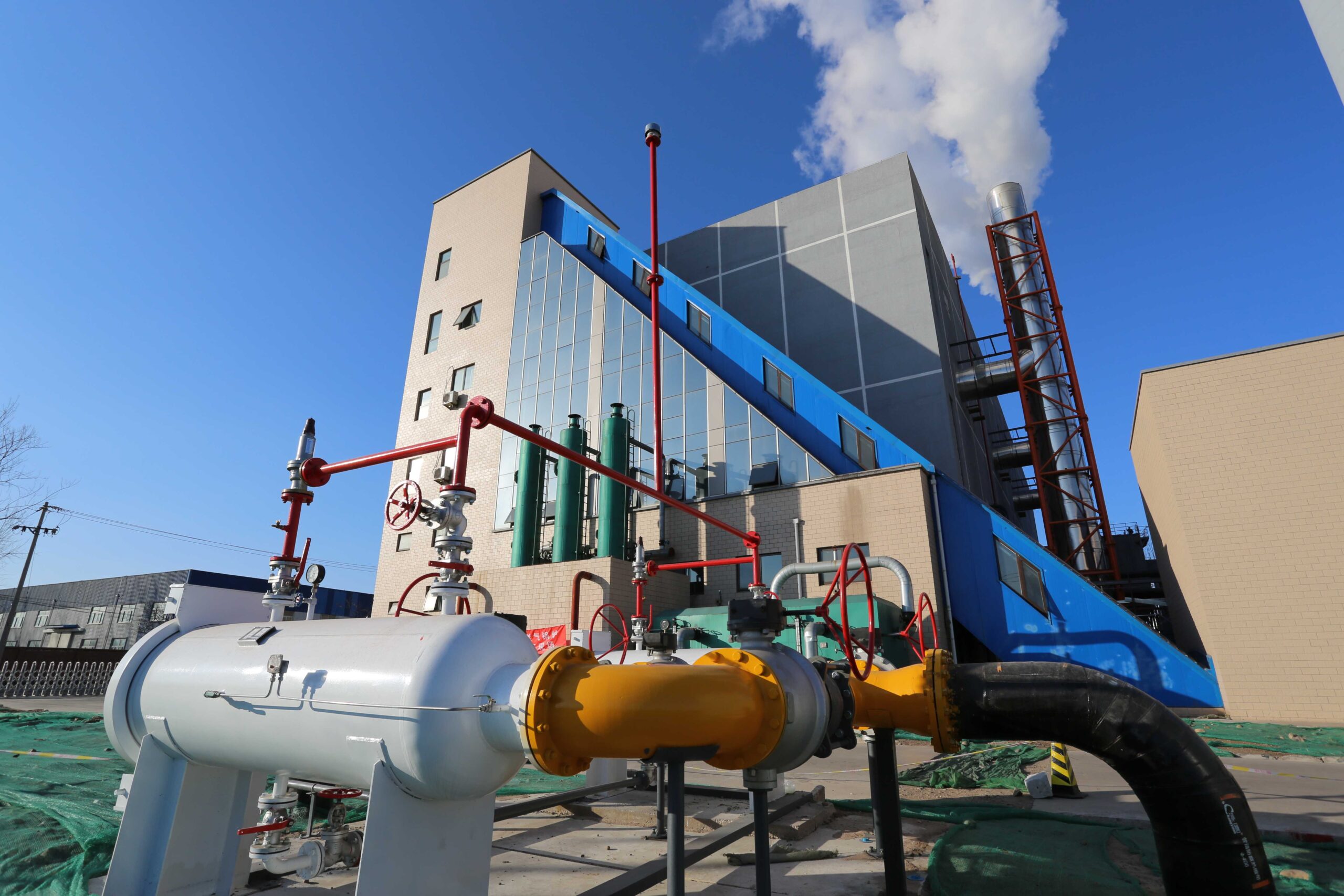
Gas-fired industrial boilers rely on a continuous and stable fuel supply to maintain efficient heat production and safe operation. If the fuel (gas) supply system fails to deliver gas at the correct pressure or composition, it can result in flame instability, incomplete combustion, equipment damage, or even hazardous explosions. These risks underline the importance of a robust and well-regulated fuel gas supply infrastructure that includes multiple safety layers, pressure controls, and monitoring systems. In this article, we’ll explore how modern fuel gas systems are engineered to ensure both reliability and safety in industrial boiler environments.
The fuel gas supply system ensures consistent and safe operation in an industrial boiler by using a series of pressure regulators, gas filters, safety shut-off valves, control valves, and monitoring sensors to deliver the correct volume of gas at a stable pressure and composition. It protects the burner from pressure fluctuations, contamination, or gas leakage, while maintaining precise control over the fuel-air ratio required for efficient and low-emission combustion. Integrated safety interlocks and alarms enable automatic shutdown in case of abnormalities, thereby preventing operational hazards and ensuring compliance with industrial safety standards.
Understanding how each part of the gas supply system works can help plant engineers and technicians better maintain system integrity, reduce downtime, and comply with increasingly strict emissions and safety codes.
Key Components of the Fuel Gas Supply System
The gas supply system feeding an industrial boiler typically includes the following major components:
| Component | Function |
|---|---|
| Gas Pressure Regulator | Ensures gas is supplied at optimal burner pressure |
| Safety Shut-Off Valve (SSOV) | Automatically shuts gas flow in emergencies |
| Gas Filter/Strainer | Removes particles and impurities from incoming gas |
| Control Valve | Modulates gas flow according to demand |
| Gas Flow Meter | Measures gas consumption for performance tracking |
| Gas Leak Detector | Detects and alarms any gas leaks in the supply system |
| Pressure Relief Valve | Releases excess gas to avoid over-pressurization |
| Flame Safeguard Controller | Monitors ignition and flame stability |
| Low/High Gas Pressure Switches | Triggers alarms or shutdown if pressure is outside safe range |
These components work in a coordinated loop to protect the system while ensuring efficient delivery of fuel to the combustion chamber.
How the System Ensures Consistency
1. Pressure Regulation
The gas entering the plant from an external supplier (e.g., utility pipeline or storage tank) is often at high pressure. A pressure regulator reduces this to a burner-suitable range (typically 20–300 mbar for low-pressure systems). Maintaining consistent pressure is crucial because fluctuations can affect flame characteristics and combustion efficiency.
2. Flow Modulation
The control valve adjusts fuel flow based on boiler load, which varies according to steam or hot water demand. Modulating gas flow ensures consistent combustion and prevents over-firing or under-firing, which could damage equipment or reduce efficiency.
3. Contaminant Removal
Gas filters or strainers trap dust, rust, or oil residues before they reach sensitive components like burners or flow meters. Clean gas promotes stable flame quality and reduces maintenance needs.
4. Redundancy and Monitoring
Modern systems often feature dual regulators, dual shut-off valves, and independent gas trains for backup. Sensors monitor parameters like gas pressure, flow, and temperature, with digital displays feeding into SCADA or DCS platforms for real-time diagnostics.
How the System Ensures Safety
Safety is built into every layer of the gas supply system. Here’s how each mechanism contributes:
| Safety Feature | Purpose |
|---|---|
| Double Shut-Off Valves (SSOV) | Stops gas flow in case of emergency or burner failure |
| Low/High-Pressure Switches | Detects abnormal pressure and trips system |
| Gas Leak Detection Alarms | Triggers automatic shutdown if leakage is detected |
| Flame Supervision (UV or IR) | Confirms flame presence; shuts system if flame is lost unexpectedly |
| Manual Reset Mechanism | Requires manual intervention to restart after shutdown |
These interlocks ensure that in the event of gas supply failure, valve malfunction, or burner issues, the system shuts down immediately to prevent accidents.
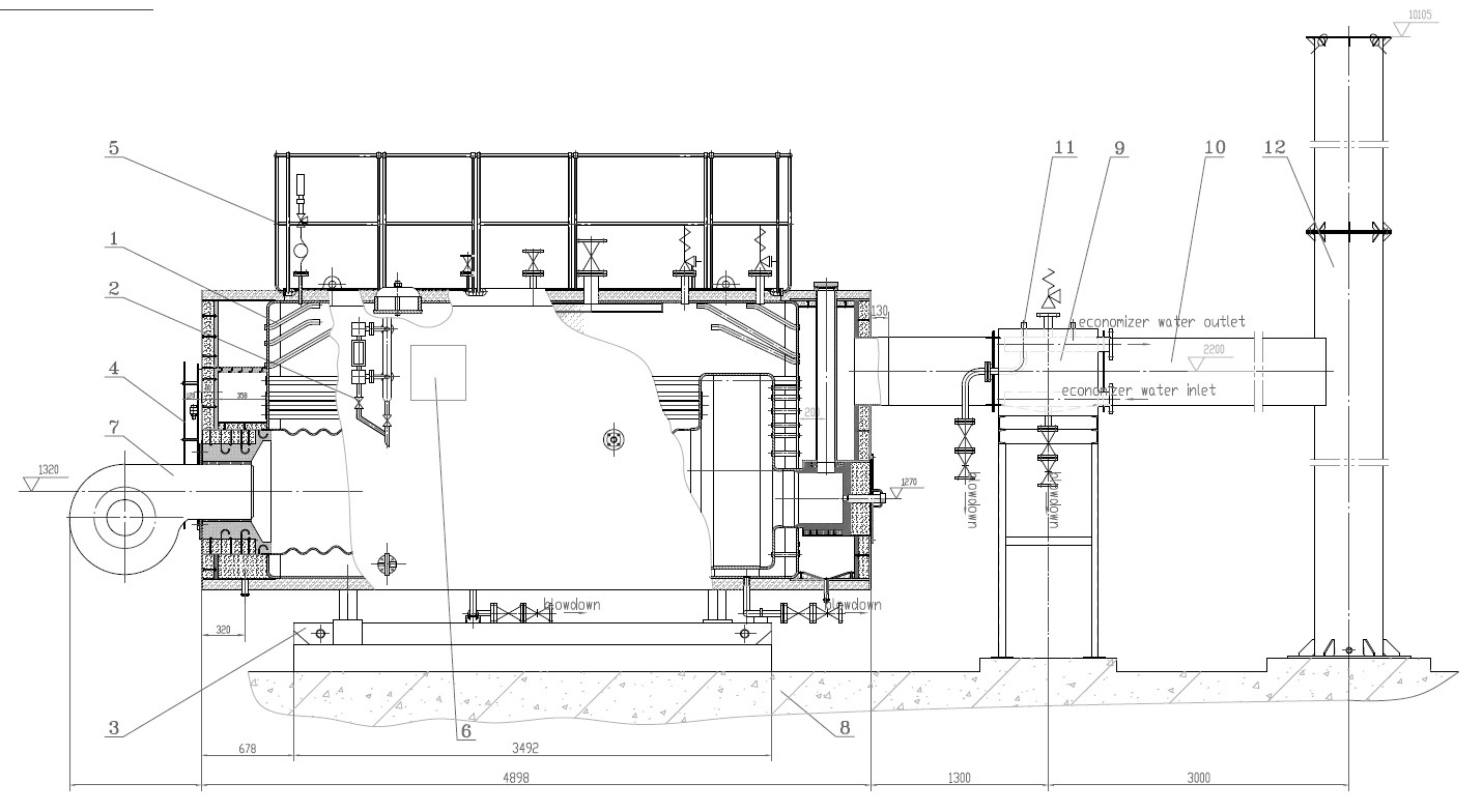
Real-World Application: Gas Flow Diagram
Below is a simplified schematic representing a typical industrial boiler gas supply system.
Natural Gas Source → Gas Filter → Pressure Regulator → Control Valve
→ Safety Shut-off Valves (1 & 2) → Flow Meter → Burner
Additional branches might include bypass lines, gas heaters (for LPG systems), or mixing manifolds for dual-fuel capability.
Monitoring and Smart Control Integration
Industrial gas supply systems are increasingly integrated with smart control platforms. These systems provide:
Real-time data on pressure, flow, and gas quality
Predictive maintenance alerts when filters or valves show signs of wear
Integration with burner management systems (BMS) to optimize fuel-air ratio
Remote diagnostics for centralized boiler operation
Such capabilities improve both safety response and efficiency monitoring, particularly in multi-boiler installations or large-scale energy plants.
Benefits of a Well-Designed Fuel Gas Supply System
Stable combustion: Consistent gas pressure and flow produce optimal flame profiles
Energy efficiency: Proper modulation prevents waste and supports low-NOx combustion
Longer equipment life: Clean and controlled fuel supply reduces burner wear
Regulatory compliance: Safety and emission standards are easier to meet
Operational uptime: Redundancy and smart alerts reduce the risk of unscheduled shutdowns
Maintenance Tips for Reliability and Safety
Regularly inspect and clean gas filters and strainers
Test pressure switches and SSOVs for correct response times
Check for gas leakage using calibrated detectors
Validate control valve calibration to maintain modulation accuracy
Periodically test flame supervision systems
A robust preventive maintenance strategy is the backbone of gas boiler safety and performance.
In summary, the fuel gas supply system is not just a passive pipeline—it’s a dynamic, safety-critical infrastructure that directly impacts the operational integrity and regulatory compliance of industrial boilers. Through precise control, real-time monitoring, and multiple safety redundancies, it ensures reliable fuel delivery, stable combustion, and secure plant operation under a wide range of operating conditions.
What is the importance of the air and flue gas handling system?
In an industrial boiler, efficient combustion and regulatory emissions control are impossible without a well-designed air and flue gas handling system. If air delivery is inconsistent or exhaust gases are not properly treated, the combustion process becomes unstable, fuel consumption increases, and pollutants exceed permissible limits—posing environmental, operational, and safety risks. To prevent these issues, industrial boilers integrate sophisticated systems to manage combustion air intake and flue gas outflow. This article explores the critical role these systems play in maintaining energy efficiency, emission compliance, and system reliability in boiler operations.
The air and flue gas handling system in an industrial boiler ensures proper combustion by delivering the correct volume of air, removing combustion by-products, recovering heat, and controlling pollutant emissions. Primary and secondary air fans regulate airflow for optimal fuel-air mixing, while induced draft (ID) fans and economizers manage exhaust flow and energy recovery. This integrated system guarantees efficient fuel burn, reduces excess air losses, supports heat recovery, and ensures emissions meet environmental regulations.
Understanding the strategic role and technical components of air and flue gas systems is essential for plant managers, energy engineers, and boiler operators aiming to optimize performance and environmental compliance.
Key Functions of the Air and Flue Gas Handling System
| Function | Description |
|---|---|
| Air Supply for Combustion | Delivers controlled air volume to support stable and complete combustion |
| Flue Gas Removal | Extracts combustion gases and expels them safely through the stack |
| Heat Recovery | Recovers residual heat from flue gases using economizers or air preheaters |
| Emission Control | Filters particulates, NOx, SOx, and other pollutants from flue gases |
| Pressure Balance and Draft Control | Maintains stable pressure and draft conditions within the boiler |
The system ensures the right air-fuel ratio, thermal efficiency, and emissions output across all operational conditions.
Major Components and Their Roles
| Component | Function |
|---|---|
| Forced Draft (FD) Fan | Supplies air to the burner; regulates combustion air volume |
| Primary Air Fan | Delivers air to the base of the furnace for drying and transporting fuel |
| Secondary Air Fan | Enhances turbulence and air-fuel mixing at the burner level |
| Induced Draft (ID) Fan | Draws flue gases from the furnace and pushes them to the stack |
| Economizer | Recovers heat from exhaust gases to preheat feedwater |
| Air Preheater (APH) | Recovers flue gas heat to preheat combustion air |
| Flue Gas Ducts | Channels flue gases between furnace, economizer, filters, and stack |
| Stack (Chimney) | Safely releases treated flue gases into the atmosphere |
| Dampers & VFDs | Modulate flow rates and pressures for air and flue gas |
These components form a continuous loop that enables optimal combustion and exhaust management.
Combustion Air System: Ensuring Stable Flame and Efficiency
The air system is responsible for delivering sufficient oxygen to combust the fuel efficiently. Combustion requires three air classifications:
Primary Air: Supports fuel drying and helps transport pulverized coal or biomass into the furnace.
Secondary Air: Injected at the burner zone for complete combustion and flame shaping.
Tertiary Air (optional): Enhances turbulence and helps reduce NOx emissions in advanced systems.
Key operational targets:
Maintain proper air-fuel ratio (stoichiometric or slightly excess)
Avoid oxygen deficiency (leads to incomplete combustion and CO formation)
Avoid excess air (leads to heat losses and lower efficiency)
A combination of dampers, sensors, and Variable Frequency Drives (VFDs) regulate airflow dynamically based on load demand and combustion quality feedback.
Flue Gas Handling System: Extracting, Treating, and Recovering
Flue gases—composed of CO₂, H₂O, N₂, O₂, NOx, SOx, and particulates—are managed through:
Induced Draft Fan (ID Fan): Maintains furnace vacuum by drawing out combustion gases.
Flue Ducts and Expansion Joints: Direct gases safely to treatment and recovery units.
Economizer: Transfers residual flue gas heat to incoming feedwater, reducing fuel demand.
Air Preheater: Heats incoming combustion air using exhaust gas heat, improving thermal efficiency.
Emission Control Units: Includes cyclones, bag filters, electrostatic precipitators (ESP), DeNOx/DeSOx scrubbers.
Stack emissions are monitored via Continuous Emissions Monitoring Systems (CEMS) to ensure regulatory compliance.
Energy Efficiency Through Heat Recovery
Flue gases typically exit furnaces at 200–400°C. Instead of wasting this thermal energy:
Economizers recover heat to raise feedwater temperature (e.g., from 60°C to 120°C), reducing energy required in the boiler drum.
Air Preheaters boost the temperature of incoming combustion air (e.g., from ambient 30°C to 150°C), enhancing combustion kinetics.
| Heat Recovery Unit | Feedwater Temperature Gain | Efficiency Gain | Fuel Savings |
|---|---|---|---|
| Economizer | +50–70°C | 3–5% | Significant |
| Air Preheater | +80–100°C | 2–4% | Moderate |
This reduces overall fuel consumption and improves thermal performance, particularly in coal, biomass, or oil-fired boilers.
Emissions Control and Compliance
Flue gas systems are critical in environmental compliance by reducing:
Particulate Matter (PM) using cyclones, baghouses, or ESPs
Nitrogen Oxides (NOx) via staged combustion, Low-NOx burners, or Selective Catalytic Reduction (SCR)
Sulfur Oxides (SOx) through limestone scrubbers or flue gas desulfurization (FGD)
Carbon Monoxide (CO) by ensuring complete combustion via optimized air delivery
| Pollutant | Primary Source | Control Technology | Reduction Efficiency |
|---|---|---|---|
| PM | Unburnt ash/residue | Cyclone, Bag Filter, ESP | 90–99.9% |
| NOx | High temp combustion | Low-NOx Burners, SCR, staged air | 60–95% |
| SOx | Sulfur in fuel | Wet/Dry Scrubbers, FGD | 80–98% |
| CO | Incomplete combustion | Burner tuning, oxygen control | >99% (with tuning) |
Integration with Boiler Control Systems
The entire air and flue gas handling system is integrated with the Boiler Management System (BMS) and Distributed Control System (DCS) for:
Automated startup/shutdown sequencing
Dynamic load adjustment
Alarm generation for airflow/flue gas faults
Air-fuel ratio optimization through real-time feedback
Smart sensors and actuators enable real-time adjustments, reducing operator workload and improving responsiveness to load variations or process changes.
Why It Matters for Plant Efficiency and Compliance
A properly designed and maintained air and flue gas handling system provides several critical benefits:
Improved fuel efficiency (2–10% depending on recovery strategy)
Reduced maintenance by limiting soot and unburnt residues
Enhanced combustion stability and flame reliability
Lower emissions meeting regulatory targets
Operational safety with managed furnace pressure and combustion atmosphere
In short, the air and flue gas handling system is the circulatory and respiratory system of the boiler—it ensures that fuel is burned completely, waste is removed safely, energy is recovered, and emissions are controlled. It’s not just a support system but a core pillar of modern boiler operation strategy.
How do modern control systems enhance boiler performance and safety?
Industrial boilers are the heart of many manufacturing and energy systems, and their performance and safety are crucial to a facility’s efficiency, productivity, and regulatory compliance. However, managing the complex variables involved in boiler operations—like fuel flow, air-to-fuel ratios, pressure, temperature, and emissions—can be challenging without automation. Manual operation leads to human error, energy waste, potential safety incidents, and increased maintenance. Modern control systems eliminate these inefficiencies by delivering precise automation, real-time monitoring, fault detection, and intelligent process optimization. In this article, we explore how these systems revolutionize boiler operations by enhancing both performance and safety.
Modern control systems enhance boiler performance and safety by automating key processes such as fuel-air ratio control, temperature regulation, pressure balance, feedwater management, and alarm handling. These systems use Programmable Logic Controllers (PLCs), Distributed Control Systems (DCS), sensors, actuators, and Human-Machine Interfaces (HMIs) to continuously monitor and optimize operations. This integration leads to improved thermal efficiency, reduced emissions, predictive maintenance, faster troubleshooting, and superior compliance with safety protocols.
Understanding the structure and function of modern boiler control systems is essential for plant managers, engineers, and operators looking to maximize operational uptime, reduce energy costs, and improve workplace safety.
Key Functional Components of a Modern Boiler Control System
| Component | Role |
|---|---|
| Programmable Logic Controller (PLC) | Executes control logic, sequences, safety interlocks |
| Distributed Control System (DCS) | Coordinates control loops across boiler subsystems for stability |
| Human-Machine Interface (HMI) | Provides user dashboard for real-time monitoring and control |
| Sensors and Transmitters | Detect temperature, pressure, flow, and oxygen levels |
| Actuators and Control Valves | Adjust fuel flow, air dampers, feedwater, steam valves |
| Safety Interlock Systems | Shuts down boiler during unsafe conditions (low water, high pressure) |
| Alarm and Event Management Module | Notifies operators of deviations or equipment faults |
Each component is integrated into a centralized or distributed control environment, ensuring fast response, precision tuning, and real-time diagnostics.
Core Functions of Boiler Control Systems
Combustion Management System (CMS)
Controls the air-fuel ratio for optimal combustion.
Uses feedback from oxygen sensors and temperature probes.
Minimizes excess air, preventing heat losses and NOx formation.
Feedwater Control System
Maintains drum level via three-element control: feedwater flow, steam flow, and drum level.
Prevents low water conditions (a major safety hazard).
Ensures stable steam output for process requirements.
Drum Pressure and Steam Temperature Control
Regulates burner output and fuel valve positioning.
Adjusts desuperheater sprays or attemperators for temperature regulation.
Maintains steam within tight pressure bands to avoid equipment stress.
Purge and Startup Sequencing
Automates safe boiler startup with furnace purging and ignition controls.
Ensures proper fan speeds, valve positions, and flame detection.
Reduces operator dependency during critical transitions.
Alarm, Safety, and Trip Logic
Detects unsafe conditions (e.g., high pressure, flame failure).
Initiates automatic shutdown procedures.
Logs alarms and sequences for diagnostics.
Emissions Monitoring and Reporting
Tracks NOx, CO, SO₂, and particulate levels using Continuous Emissions Monitoring Systems (CEMS).
Adjusts combustion parameters for compliance.
Performance Benefits of Modern Boiler Controls
| Performance Area | Traditional Boilers | Modern Control Systems |
|---|---|---|
| Fuel Efficiency | Manual tuning, higher fuel loss | Auto-optimization, better fuel economy |
| Steam Pressure Stability | Fluctuations, risk of tripping | Tight regulation, high reliability |
| Oxygen Trim Control | Absent or delayed response | Real-time excess O₂ adjustment |
| Load Following | Manual ramp-up/down | Smooth load transitions |
| Heat Rate | Variable | Consistent and lower heat rate |
Modern control algorithms allow adaptive learning from load patterns and equipment behavior, further improving outcomes over time.
Safety Enhancements from Integrated Control
Modern systems not only optimize performance but also significantly boost safety:
Redundant logic in critical paths ensures safety interlocks always trigger on faults.
Flame scanners detect flame presence and initiate immediate shutdown on failure.
High-temperature cutoffs and pressure relief valve monitoring prevent overpressure or overheating.
Fail-safe valve positions and power redundancy protect the system during electrical outages.
| Safety Feature | Function |
|---|---|
| Burner Management System (BMS) | Manages ignition, flame supervision, purge cycles |
| Safety Instrumented System (SIS) | Independently verifies critical limits and executes emergency shutdown |
| Emergency Shutdown (ESD) Logic | Trips boiler upon any breach of safe operational limits |
| Historical Event Recording | Supports investigation and root-cause analysis of faults and incidents |
These layers of safety help meet regulatory codes such as NFPA 85 (Boiler and Combustion Systems Hazards Code) and IEC 61511 (SIS for Process Industries).
Advanced Features: Digital Twin and Predictive Maintenance
Some modern control systems include:
Digital Twins: Real-time virtual models of boiler operations for simulation and diagnostics.
Predictive Maintenance Analytics: Uses vibration, temperature, and operational data to forecast equipment failures.
Remote Monitoring: Enables 24/7 off-site access for specialists via secure networks.
These capabilities reduce unplanned downtime, extend equipment life, and lower total cost of ownership (TCO).
| Feature | Value Addition |
|---|---|
| Digital Twin Modeling | Scenario simulation, performance optimization |
| Predictive Maintenance | Condition-based servicing, reduced breakdowns |
| Remote Access and Cloud Sync | Global support, cross-plant performance comparison |
| AI/ML Integration | Anomaly detection, combustion tuning, efficiency alerts |
Integration with SCADA and Industrial IoT Platforms
Modern control systems are designed to integrate with Supervisory Control and Data Acquisition (SCADA) systems and Industrial Internet of Things (IIoT) platforms for:
Centralized monitoring of multiple boilers or plant units
Aggregated data visualization and reporting
Real-time energy consumption tracking
Environmental performance audits
This connectivity creates a digital ecosystem where operators can make data-driven decisions for efficiency, sustainability, and safety.
Real-World Impact and Industry Examples
In a pulp and paper plant in Finland, implementing a modern boiler control system led to:
6% reduction in fuel consumption
20% drop in unplanned downtime
Full compliance with EU industrial emissions directives
Similarly, a steel mill in India improved steam pressure stability from ±4 bar to ±0.8 bar, improving product consistency and reducing material rejection.
Industrial segments where control system benefits are particularly impactful include:
Chemical and petrochemical refineries
Power generation and cogeneration plants
Food processing and breweries
Pharmaceutical manufacturing
Textile dyeing and finishing
These industries often operate 24/7 and require precision steam control and fail-proof safety.
Final Thoughts
Modern boiler control systems are no longer optional add-ons—they are foundational to any high-performance industrial steam or thermal energy system. By delivering automation, precision, and predictive intelligence, these systems unlock significant improvements in fuel efficiency, emission reduction, equipment longevity, and plant safety. For industrial operators facing rising energy costs and tighter environmental regulations, investing in intelligent control systems is a strategic move toward operational excellence.
🔍 Conclusion
Understanding the key components of an industrial gas-fired boiler is crucial for achieving maximum efficiency, safe operation, and environmental compliance. Each element, from the gas burner to the control system, contributes to the boiler’s ability to deliver consistent and clean thermal energy. With proper knowledge and system optimization, industries can reduce fuel costs, enhance uptime, and extend the equipment’s lifespan.
📞 Contact Us
💡 Need expert insight on industrial gas-fired boilers? Whether you’re planning a new installation or upgrading your current system, our team offers customized solutions for efficiency, safety, and performance.
🔹 Contact us today to enhance your industrial gas boiler system! 🔧🔥
