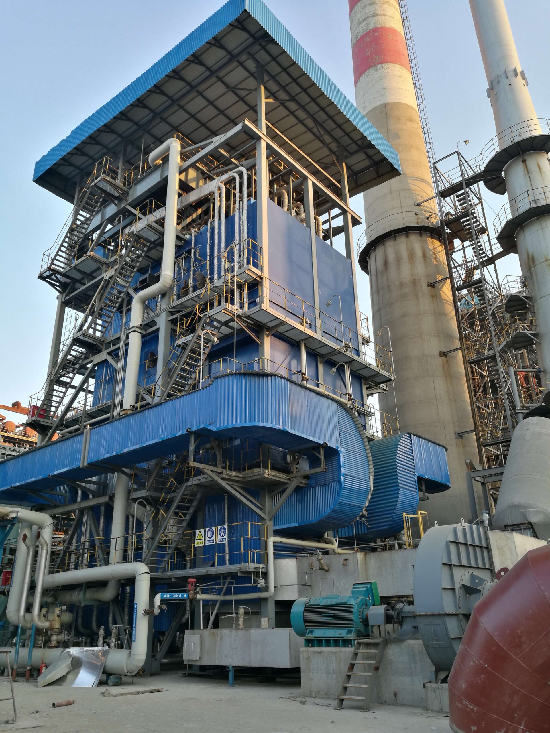
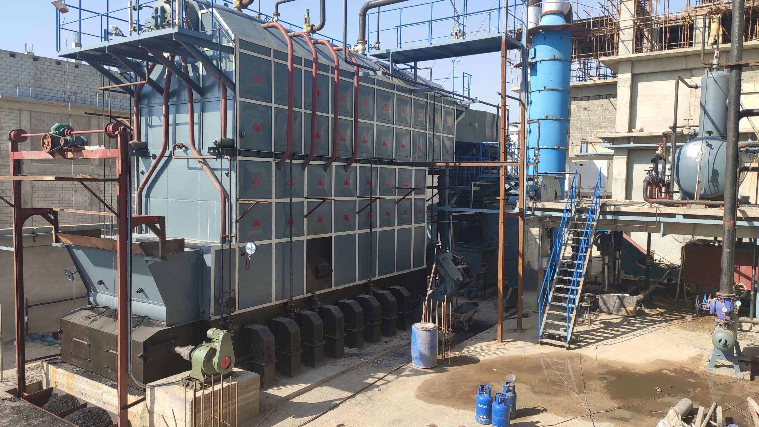
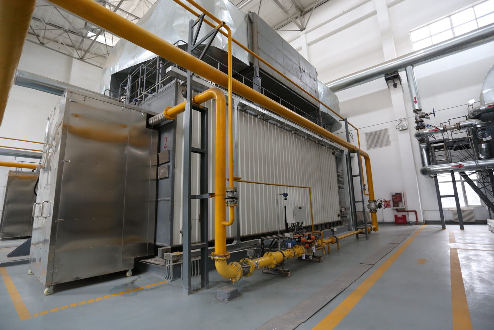
Industrial boilers are essential systems used in factories, power plants, and processing facilities to generate steam or hot water for heating, power generation, or process operations. But beyond the outer shell lies a complex assembly of mechanical, thermal, and control components working together to ensure safe, efficient, and reliable operation. Understanding what’s inside an industrial boiler is key to proper maintenance, efficiency optimization, and system selection.
An industrial boiler typically contains a pressure vessel (drum), combustion chamber (furnace), heat exchanger tubes, burner system, feedwater system, flue gas exhaust system, control panel, and safety devices. Depending on the boiler type (fire-tube, water-tube, fluidized bed, etc.), the internal configuration and working principles vary—but all components are designed to transfer heat from fuel combustion to water or steam while ensuring pressure control, energy efficiency, and safe operation.
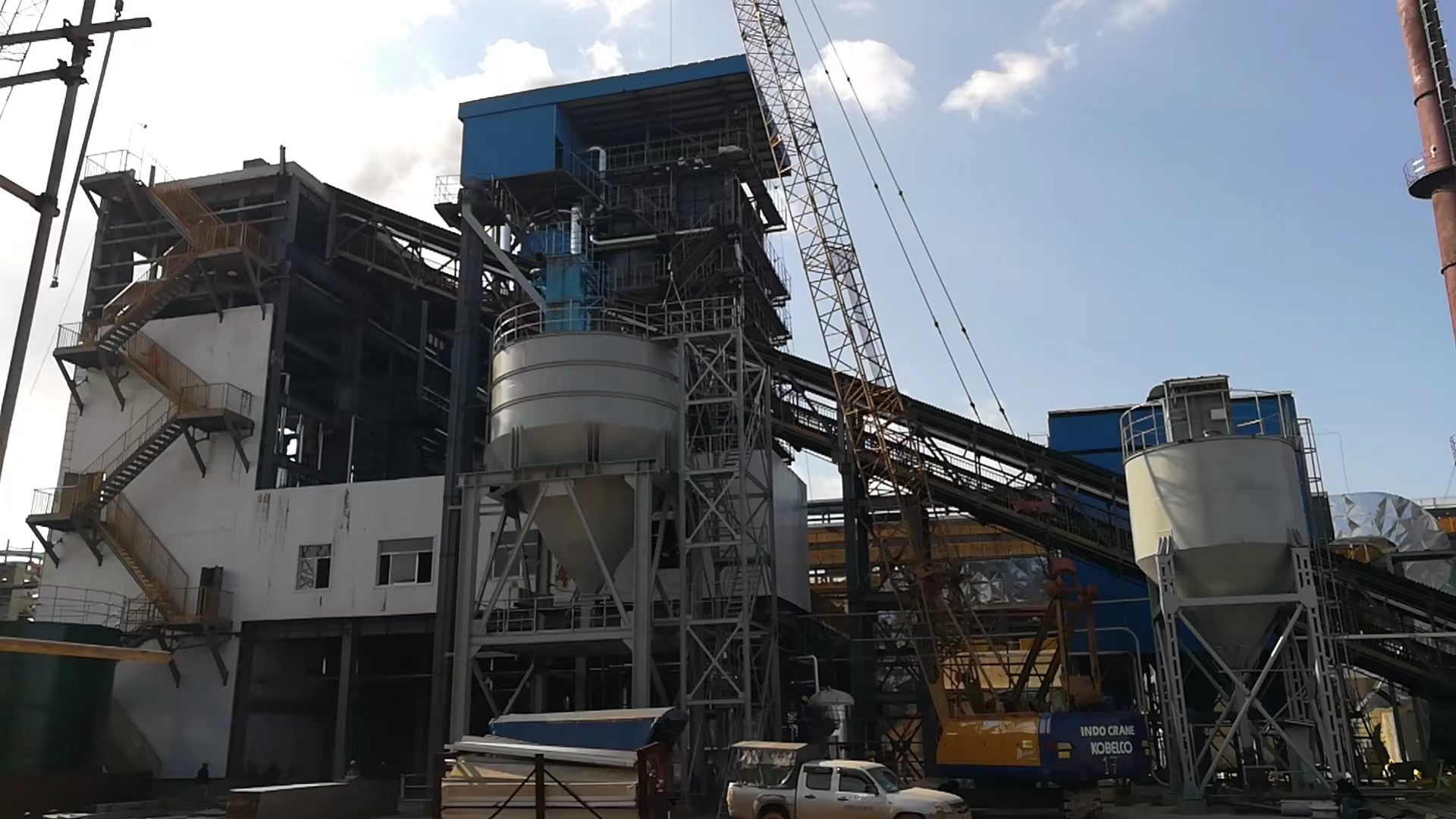
Here’s a detailed breakdown of the main components inside an industrial boiler system.
What Is the Function of the Pressure Vessel and How Does It Contain High-Pressure Steam or Water?
At the heart of every industrial boiler lies the pressure vessel—a critical component responsible for containing high-pressure steam or water under controlled conditions. Whether in a utility-scale CFB boiler, a biomass-fired system, or a gas/oil package boiler, the pressure vessel must withstand elevated temperatures, internal pressure, and thermal cycling—without cracking, leaking, or deforming. A failure in this structure can result in catastrophic explosions, process downtime, or safety violations.
The pressure vessel’s function is to safely contain and regulate pressurized steam or water generated by combustion, using a welded steel enclosure, seamless tubing, and pressure-rated components such as steam drums, water walls, and headers. It maintains pressure integrity through ASME/CE-compliant design, tested materials, controlled welding, and continuous monitoring of wall temperature, thickness, and pressure.
This vessel isn’t just a container—it’s a fortress of steam.
The pressure vessel in an industrial boiler is designed to safely contain and manage high-pressure steam and water.True
Through engineered materials, certified welding, and design codes like ASME Section I, the pressure vessel prevents rupture or failure even under extreme thermal and pressure loads.
Key Functions and Design Features of a Boiler Pressure Vessel
1. Core Function: Steam or Water Containment Under Pressure
| System Element | Function |
|---|---|
| Steam drum | Collects and holds generated steam at pressure |
| Water walls | Circulate water along furnace walls to absorb radiant heat |
| Mud drum | Collects solids and sediment from water loop |
| Riser/downcomer tubes | Create natural or forced circulation of water-steam mixture |
The pressure vessel ensures that the pressurized medium (usually >10 bar, up to 200+ bar) is safely separated from the combustion process, external air, and mechanical support systems.
Ask your supplier:
What is the design pressure and temperature rating of the vessel?
How is pressure monitored and relieved in case of overpressure?
2. How It Contains Pressure: Material Strength and Geometry
| Pressure Vessel Feature | Design Strategy |
|---|---|
| Cylindrical shape (drum) | Minimizes stress under internal pressure |
| SA-516, SA-387, or equivalent steel | High tensile and creep strength |
| Welded construction with RT or UT | Prevents leaks, complies with ASME/CE codes |
| Seamless tubes (e.g. SA-210, SA-192) | Withstand expansion, erosion, and thermal shock |
The thickness of the shell, number of expansion joints, and reinforcement rings are all calculated via pressure vessel codes (ASME Section I or EN 13445) using:
t=P⋅R/(S⋅E−0.6P)
Where:
t = required thickness
P = internal pressure
R = inner radius
S = allowable stress
E = weld joint efficiency
Ask your supplier:
What stress calculations and finite element analysis were performed?
Are pressure parts certified with EN 10204 3.1 material test certificates?
3. Structural Integrity via Code Compliance and Testing
| Code Requirement | Why It Matters |
|---|---|
| ASME Section I / CE PED | Ensures design pressure, material, and construction quality |
| Hydrostatic testing | Verifies vessel integrity at 1.5x working pressure |
| Nondestructive Testing (NDT) | Confirms weld quality using RT, UT, MT, or PT |
| Post-weld heat treatment (PWHT) | Relieves thermal stress from welding |
| Corrosion allowance | Extra thickness to extend lifespan under erosion or scaling |
Ask:
Is the vessel ASME “S”-stamped or CE Module H-certified?
Was hydrotesting performed with proper instrumentation and hold time?
Is the design corrosion allowance ≥3 mm for high-temperature operation?
4. Internal Monitoring and Protection Systems
| Monitoring Device | Function |
|---|---|
| Pressure gauge + transmitter | Real-time pressure reading for control logic |
| Safety relief valve | Vents steam if pressure exceeds limits |
| Water level gauge + probe | Prevents dry firing and overheating |
| Temperature sensor (skin and internal) | Prevents overheat or creep |
| Corrosion coupons or ultrasonic probes | Tracks wear and thinning over time |
Advanced boilers include:
Remote SCADA monitoring of wall pressure and drum level
Tube failure detection sensors
Redundant safety valves with interlock logic
Ask:
What interlocks protect against vessel overpressure or dry run?
Are internal sensors calibrated to ISO 17025 or equivalent?
Example: 120 TPH High-Pressure Biomass CFB Boiler
Design pressure: 92 bar
Design temperature: 540°C
Material: SA-516 Gr.70 drum, SA-210 tubes
Code: ASME Section I with “S” stamp
Testing:
Hydrotested to 138 bar
100% RT on main welds
PWHT performed at 625°C
Relief valve set at 96 bar (110% margin)
Monitoring:
Dual pressure transmitters + mechanical gauge
2-out-of-3 logic for water level trip
Thermal imaging zone scans performed every 3 months
Wall thinning tracked by ultrasonic probe array
Summary
Your boiler’s pressure vessel is the backbone of its reliability—and the guardian of its safety. It’s not just steel; it’s a carefully calculated, tested, and certified structure designed to manage the volatile power of steam under pressure. Ask for the math, the metallurgy, and the monitoring. Choose a vessel that’s built to withstand pressure—not just generate it. Choose a supplier whose pressure parts are proofed, not just promised. Choose strength backed by standards.
What Roles Do the Furnace and Burner Play in Fuel Combustion and Heat Generation?
At the heart of every industrial boiler lies the furnace and burner system—the engineered interface where fuel energy is converted into heat energy. Whether burning natural gas, oil, coal, biomass, or waste fuels, this combination is what initiates and sustains the combustion process. Poor burner performance or an improperly designed furnace can lead to low efficiency, high emissions, flame instability, or even catastrophic failure.
The burner is responsible for delivering a controlled, stable flame by atomizing or injecting fuel into the combustion chamber, mixing it with air, and igniting it. The furnace surrounds the flame zone, contains the radiant heat, and directs it to the water walls or tubes, enabling rapid heat transfer to generate high-pressure steam. Together, they form the core combustion and heat generation system in any boiler.
Combustion starts at the burner—but it lives and works inside the furnace.
The burner initiates combustion by delivering and igniting the fuel-air mixture, while the furnace contains the flame and directs heat to water walls or tubes.True
This coordinated system enables efficient heat transfer to the pressure vessel and stable steam production, ensuring the boiler operates safely and effectively.
Roles and Functions of the Burner and Furnace in an Industrial Boiler
1. What Does the Burner Do in the Combustion Process?
| Burner Function | Role in Combustion |
|---|---|
| Fuel delivery | Feeds liquid, gas, or pulverized solid fuel into flame zone |
| Air mixing | Regulates primary, secondary, and sometimes tertiary air |
| Atomization (oil/gas) | Breaks fuel into fine droplets or jets for better ignition |
| Flame stabilization | Maintains consistent flame shape and size for safe burning |
| Ignition | Uses pilot flame or electric arc to initiate combustion |
| Turndown ratio management | Adjusts fuel/air to match boiler load demand |
Ask your supplier:
What turndown ratio does the burner support (e.g., 10:1, 5:1)?
How is air-fuel ratio controlled (mechanical linkage or PLC)?
Is the burner low-NOₓ, staged combustion, or FGR-equipped?
2. What Is the Function of the Furnace in Heat Transfer?
| Furnace Component | Function |
|---|---|
| Furnace enclosure | Contains the flame and radiant heat |
| Water walls | Absorb radiant heat and convert water to steam |
| Refractory or membrane walls | Reflect heat inward, protect structural steel |
| Combustion chamber geometry | Ensures complete combustion and minimizes CO/NOₓ |
| Flue gas outlet | Guides hot gases toward convection banks or economizer |
The furnace must withstand extreme flame temperatures (>1,200°C) while ensuring complete combustion and minimizing unburnt particles. It also channels the radiant energy into the pressurized water system.
Ask your supplier:
What is the furnace volume and residence time for our fuel?
Is the enclosure membrane wall or refractory lined?
What is the water wall coverage ratio (usually ≥65–70%)?
3. How the Burner and Furnace Work Together
| Parameter | Burner Influence | Furnace Influence |
|---|---|---|
| Flame length | Adjusted by fuel/air mix | Contained within chamber design |
| Emissions (NOₓ/CO) | Controlled by staged air, FGR | Affected by temperature and residence time |
| Combustion efficiency | Air-fuel tuning | Turbulence and burnout zone size |
| Heat flux | Flame shape and orientation | Tube surface area and emissivity |
| Load response | Burner modulation speed | Furnace thermal inertia |
Successful design requires matching the burner’s flame characteristics to the furnace’s geometry to prevent flame impingement, excessive quenching, or incomplete combustion.
4. Monitoring and Control Systems
| System | Monitored Variable | Purpose |
|---|---|---|
| Flame scanner | Flame presence and stability | Trip protection and safety interlock |
| Oxygen analyzer | Flue gas O₂ | Air-fuel tuning and efficiency control |
| Furnace draft sensor | Internal negative pressure | Prevent backfire or leakage |
| Temperature sensors | Flame temperature, water wall skin | Overheat protection and load tracking |
These systems ensure that combustion remains safe, stable, and efficient under varying load and fuel conditions.
5. Example: 50 TPH Oil/Gas Boiler with Integrated Burner-Furnace Design
Fuel: Natural gas + No. 2 oil (dual-fuel)
Burner: Modulating burner, 10:1 turndown, low-NOₓ staged combustion
Furnace: Fully membrane wall enclosure, 18 m³ volume, 2.6 seconds residence time
Monitoring:
UV scanner for flame detection
O₂ analyzer linked to VFD-controlled FD fan
Draft control via damper feedback loop
Burner control logic on PLC with SCADA interface
Performance:
Combustion efficiency: 92.8–95.4%
NOₓ: <50 mg/Nm³ (with FGR active)
CO: <20 mg/Nm³ across load range
Startup time (cold): 18–22 minutes to full flame
Summary
The burner and furnace are the combustion core of your industrial boiler—igniting the fuel, shaping the flame, and transferring the energy that powers your process. Whether it’s oil, gas, coal, or biomass, you need a system that’s harmonized, monitored, and optimized for your specific fuel and load profile. Ask for performance data, flame geometry, turndown specs, and emissions logs—not just burner brochures. Choose combustion that burns clean, controls tight, and heats with purpose. Choose a furnace and burner duo designed to deliver fire with focus.
How Do Heat Exchanger Tubes Transfer Thermal Energy to Water or Steam?
Inside every industrial boiler, heat exchanger tubes are the primary pathway that converts combustion energy into steam power. Whether in a fire-tube or water-tube design, these tubes form the critical interface between hot combustion gases and pressurized water or steam. Their job: to absorb, transfer, and distribute heat efficiently while withstanding extreme temperature, pressure, and corrosion conditions.
Heat exchanger tubes transfer thermal energy to water or steam by absorbing radiant and convective heat from hot flue gases and conducting it through their walls into the fluid inside. This process involves conduction through the metal tube wall, convection from the gas to the tube surface, and phase change from water to steam inside the tube. In water-tube boilers, this results in high-pressure, high-temperature steam generation.
These tubes are the arteries of the boiler’s thermal system, turning fuel into usable energy, safely and continuously.
Heat exchanger tubes in industrial boilers transfer heat through conduction and convection, enabling water to convert into steam under pressure.True
Hot combustion gases flow over the external surface of the tubes, heating the water or steam inside via metal conduction, with carefully engineered materials ensuring safe and efficient thermal transfer.
Mechanism of Heat Transfer Inside Boiler Tubes
1. Thermodynamic Steps of Heat Transfer
| Stage | Process | Physical Mechanism |
|---|---|---|
| 1. Combustion | Flame heats up surrounding gases | Radiant heat absorption |
| 2. Gas-tube interface | Hot gases contact outer tube surface | Convective heat transfer |
| 3. Tube wall | Heat travels through steel wall | Thermal conduction |
| 4. Inside tube | Water absorbs heat | Convection + phase change (evaporation) |
| 5. Steam generation | Steam rises or is collected in steam drum | Saturated or superheated steam output |
The governing equation:
Q=U⋅A⋅ΔTQ
Where:
Q = heat transferred (W)
U = overall heat transfer coefficient (W/m²·K)
A = surface area of tube (m²)
ΔT = temperature difference between hot gas and water/steam
2. Types of Heat Transfer Involved
| Heat Transfer Mode | Where It Occurs | Why It Matters |
|---|---|---|
| Radiative transfer | Furnace zone, to water walls | Most intense heat, >50% total energy |
| Convective transfer | Gas flow across economizers/superheaters | Driven by flue gas velocity |
| Conductive transfer | Through the tube wall metal | Controlled by wall thickness and material |
| Nucleate boiling | Inside water tubes at saturation point | Maximizes thermal transfer efficiency |
Ask your supplier:
What tube material is used (e.g., SA-210, SA-213, T11, T22)?
How is internal water flow arranged—natural circulation or forced?
Are tube surfaces enhanced (finned, rifled, coated) to increase efficiency?
3. Common Tube Configurations in Water-Tube Boilers
| Tube Bank Type | Function | Location in Boiler |
|---|---|---|
| Water walls | Absorb radiant heat | Furnace chamber sides and roof |
| Superheater tubes | Raise steam temp > saturation | Post-radiant zone |
| Economizer tubes | Preheat feedwater using flue gas | Last pass of flue gas path |
| Reheater tubes | Reheat steam post-turbine stage | Secondary steam loop (power plants) |
4. Tube Design Considerations for Thermal Efficiency and Safety
| Factor | Design Solution |
|---|---|
| Heat stress | Alloy steel with high creep resistance (T91, T22) |
| Thermal expansion | Expansion loops, tube hanger supports |
| Erosion from flue gas | Tube shields, gas deflectors, flow design |
| Fouling or scaling | Blowdown systems, internal treatment chemicals |
| Tube rupture protection | Safety interlocks, water level alarms, NDT inspection routines |
5. Example: High-Pressure CFB Boiler Heat Transfer Tubes
Fuel: Petcoke + biomass (abrasive fuel)
Tube Types:
Membrane water walls: SA-210A1 seamless tubes
Superheater tubes: SA-213 T11 alloy steel, 3.5 mm thickness
Economizer tubes: Fin-type, carbon steel SA-192
Refractory shielding: In cyclone inlet zone to reduce radiant tube damage
Performance:
Overall heat transfer coefficient (U): 80–120 W/m²·K
Steam outlet temp: 540°C @ 100 bar
Surface area: 14,600 m² of heat transfer tube surface
Estimated steam generation efficiency: 88.6% thermal
Summary
The heat exchanger tubes inside an industrial boiler are where fuel becomes function—turning flame and gas into pressurized steam through a finely tuned balance of physics, metallurgy, and geometry. Ask your supplier how their tube design handles heat, pressure, erosion, and fouling, and how long it will sustain that transfer with minimal loss. Choose tubes that don’t just carry heat—they carry your plant’s performance. Choose transfer engineered for longevity, safety, and efficiency. Choose tubing that turns heat into horsepower.
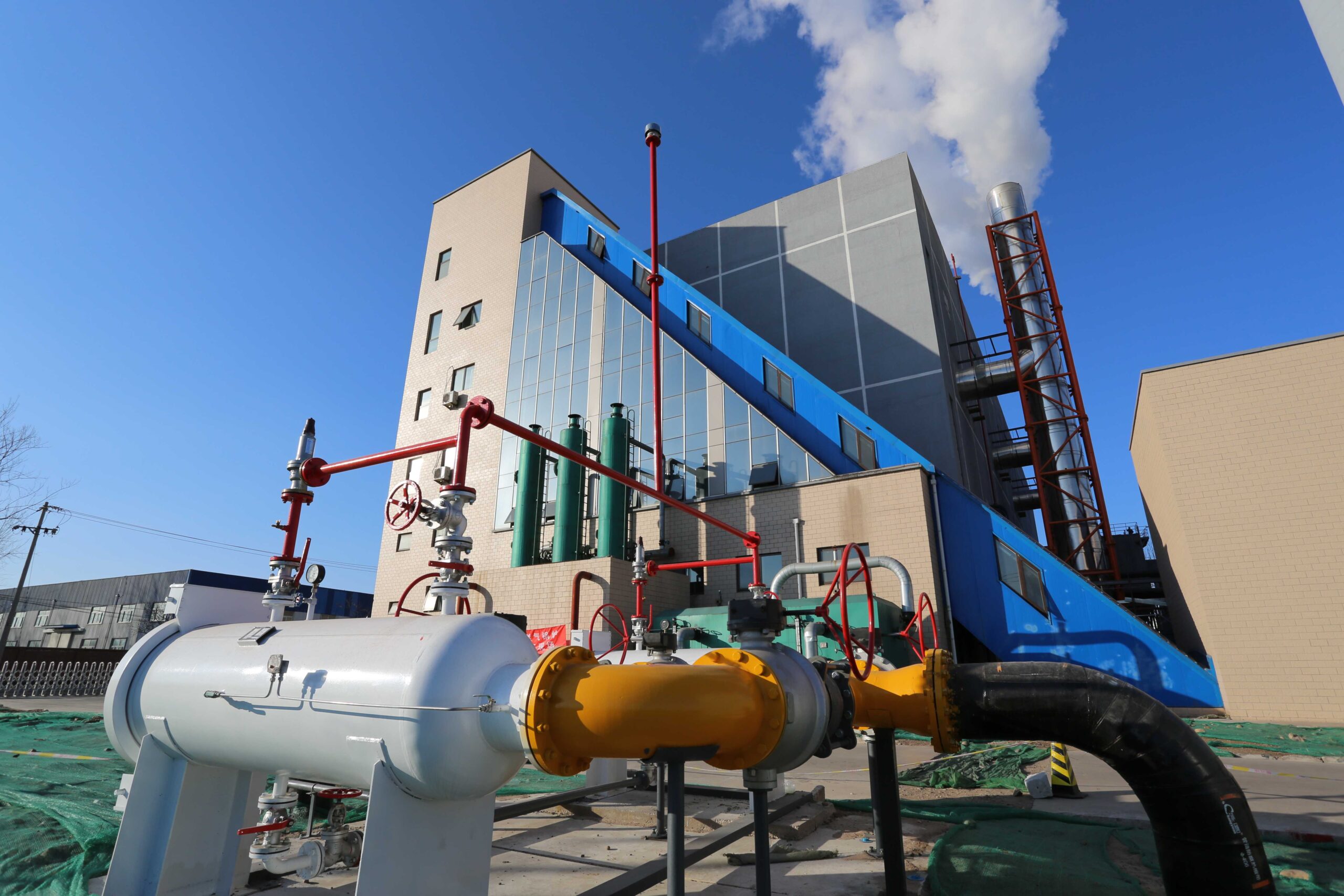
What Auxiliary Systems (Feedwater Pumps, Deaerators, Economizers) Support Boiler Operation?
While the furnace, burner, pressure vessel, and heat exchanger tubes form the thermal core of an industrial boiler, auxiliary systems are what make it function safely, continuously, and efficiently. Without reliable support systems like feedwater pumps, deaerators, and economizers, even the best boiler will suffer from pressure instability, thermal shock, corrosion, or fuel inefficiency.
Auxiliary systems such as feedwater pumps, deaerators, economizers, blowdown systems, and condensate recovery loops support boiler operation by managing water input, oxygen removal, preheating, and pressure control. These components ensure steady steam generation, prolong equipment life, reduce energy losses, and maintain safe operating conditions.
Think of them as the circulatory, respiratory, and sensory systems of your boiler—not just accessories, but critical to survival.
Auxiliary systems like feedwater pumps, deaerators, and economizers are essential to ensure safe, efficient, and continuous boiler operation.True
They regulate water supply, reduce oxygen corrosion, recover heat, and balance steam demand, ensuring optimal thermal and mechanical performance in industrial boilers.
Key Auxiliary Systems Supporting Industrial Boiler Operation
1. Feedwater Pumps – Driving the Circulation
| Function | Delivers treated water into the boiler drum or economizer at high pressure |
|---|---|
| Types | Multistage centrifugal pumps (horizontal/vertical), turbine-driven, motor-driven |
| Control | VFD (variable frequency drive) or control valve modulation to match load |
| Monitoring | Flow meters, pressure transmitters, suction filters, NPSH sensors |
Importance:
Maintains boiler water level
Ensures high-pressure injection (up to 200 bar+)
Prevents cavitation and dry-run failures
Ask:
What is the pump head and flow rate required for my design pressure?
Is the pump duplexed (1 working + 1 standby)?
Is there auto-switching logic during pump failure?
2. Deaerators – Removing Dissolved Oxygen
| Function | Eliminates oxygen (O₂) and carbon dioxide (CO₂) from feedwater to prevent corrosion |
|---|---|
| Types | Tray-type, spray-type, or combined tray/spray deaerators |
| Operating pressure | Typically 0.1–0.3 MPa (1–3 bar) |
| Vent condenser | Recovers steam flash losses and minimizes oxygen re-entrainment |
Importance:
Prevents corrosion in economizers, tubes, and drums
Increases system lifespan
Preheats feedwater to near saturation
Ask:
What is the O₂ removal efficiency (typically <7 ppb)?
Is the tank insulated and vented with flash recovery?
Do you provide level and pressure control integration?
3. Economizers – Recovering Flue Gas Heat
| Function | Preheats boiler feedwater using residual heat from flue gas exiting the furnace |
|---|---|
| Material | Carbon steel, alloy steel (for high-temp systems) |
| Tube configuration | Bare tube, finned tube, inline or staggered |
| Heat gain | Raises feedwater temp from ~100°C to 140–180°C (depending on steam drum pressure) |
Importance:
Improves boiler thermal efficiency by 5–10%
Reduces fuel consumption
Lowers flue gas temperature and stack loss
Ask:
What is the gas-side pressure drop and its effect on fan sizing?
Is the economizer equipped with soot blowers for cleaning?
Are inlet/outlet temperatures monitored for scaling detection?
4. Condensate Recovery System – Closing the Loop
| Function | Returns condensed steam (from heat exchangers or traps) to the feedwater system |
|---|---|
| Components | Flash tanks, condensate pumps, return lines, steam traps |
| Control | Level control in tanks, pressure relief systems |
Importance:
Reduces makeup water demand
Recovers sensible heat and reduces fuel use
Minimizes thermal shock in feedwater inlet
Ask:
Is the system insulated to avoid heat loss?
Are traps regularly maintained or auto-diagnosed?
Do you track condensate return percentage (target ≥75%)?
5. Blowdown System – Managing Water Quality
| Function | Discharges part of the boiler water to control TDS (total dissolved solids) and prevent scaling |
|---|---|
| Types | Continuous (surface), intermittent (bottom blowdown) |
| Control | Automated blowdown valves, conductivity sensors, blowdown heat recovery units |
Importance:
Prevents scale, tube overheating, and efficiency loss
Maintains steam purity
Reduces chemical costs when properly automated
Ask:
Are blowdown rates controlled via real-time TDS?
Is heat recovery integrated in the blowdown tank?
What is your recommended blowdown frequency per load level?
Example: 60 TPH Industrial Biomass Boiler Auxiliary Systems
| Component | Specification |
|---|---|
| Feedwater pump | 2 × 55 kW multistage pumps, 180 m³/h @ 32 bar |
| Deaerator | Spray-type, 5 m³ tank, oxygen <5 ppb |
| Economizer | 340 m² finned tube, raises water temp from 105°C to 165°C |
| Condensate system | 2.5 bar recovery loop, 82% return rate |
| Blowdown | Automated surface blowdown with heat recovery exchanger |
Results:
6.3% overall fuel savings from economizer + condensate integration
18-month ROI on deaerator + recovery system
Reduced boiler water treatment chemical usage by 27%
Summary
The thermal core of a boiler may burn the fuel, but the auxiliary systems deliver the water, recover the heat, remove the oxygen, and close the loop. Ask your supplier how each of these systems is designed, integrated, and maintained in your plant. Choose a boiler that’s supported not just by steel—but by a smart balance-of-plant strategy. Choose efficiency that flows with every drop. Choose auxiliaries that make combustion complete.

How Is Flue Gas Managed Through Chimneys, Air Preheaters, and Pollution Control Equipment?
In industrial boilers, the by-product of combustion is flue gas—a high-temperature, chemically reactive mixture of CO₂, H₂O vapor, NOₓ, SOₓ, CO, PM (particulate matter), and excess oxygen. If not carefully managed, this gas stream can cause heat loss, emissions violations, equipment erosion, and community health risks.
Flue gas is managed through a controlled sequence of systems: air preheaters to recover heat, pollution control equipment (e.g., ESPs, baghouses, scrubbers) to capture emissions, and chimneys or stacks to safely disperse cleaned gas into the atmosphere. Each stage reduces waste, improves efficiency, and ensures regulatory compliance.
The journey of flue gas is as important as the flame that created it.
Industrial boiler flue gas is managed through energy recovery and emissions control systems including air preheaters, scrubbers, and stacks.True
These systems reduce environmental impact, improve boiler efficiency, and meet regulatory emissions limits by treating the gas before atmospheric release.
Step-by-Step Flue Gas Management Path in Industrial Boilers
1. Air Preheater (APH): Recovering Thermal Energy
| Function | Transfers residual flue gas heat to combustion air |
|---|---|
| Types | Rotary regenerative (Ljungström), recuperative plate/tube |
| Temperature drop | Reduces flue gas from ~350–450°C to ~180–220°C |
| Air preheat gain | Raises incoming air from ambient to 150–200°C |
Benefits:
Increases combustion efficiency by 2–5%
Reduces fuel consumption and stack loss
Lowers flue gas temperature for better ESP/baghouse operation
Ask:
What is the leakage rate of the APH seals?
Are seals, baskets, and sectors replaceable?
Is the APH protected against acid dew point corrosion?
2. Pollution Control Equipment: Capturing Harmful Emissions
| Device | Pollutant Controlled | Efficiency |
|---|---|---|
| Electrostatic Precipitator (ESP) | Particulate matter (PM₁₀, PM₂.₅) | 98–99.9% |
| Baghouse (Fabric Filter) | Fine dust and unburned ash | 99.5–99.99% |
| Desulfurization System (WFGD/DSD) | SO₂ | 90–99% |
| SNCR/SCR | NOₓ | 60–95% |
| Activated Carbon Injection (ACI) | Heavy metals, dioxins | 70–90% |
ESP: Charges dust particles and attracts them to collection plates
Baghouse: Filters ash using high-temp cloth filter bags
Wet FGD: Sprays limestone slurry to absorb SO₂
SNCR: Injects ammonia/urea into furnace to neutralize NOₓ
SCR: Uses catalyst downstream of APH to decompose NOₓ at 300–400°C
Ask:
What PM, NOₓ, and SO₂ emission limits does your system meet?
Are all control systems SCADA-integrated with alarm limits?
How often are filter bags or electrodes serviced?
3. Induced Draft (ID) Fan: Maintaining Negative Pressure
| Function | Pulls flue gas through the boiler and pollution control system to the chimney |
|---|---|
| Control | VFD speed regulation to match load and draft requirements |
| Monitoring | Draft pressure sensor, vibration monitor, bearing temp sensors |
Importance:
Keeps furnace under negative pressure
Prevents backflow or gas leakage into boiler room
Maintains flue gas velocity through ESP and stack
Ask:
Is the fan oversized for future capacity increase?
Are dampers automated?
Is the fan vibration- or temperature-protected?
4. Chimney (Stack): Safe Dispersion to Atmosphere
| Function | Discharges cleaned flue gas at height to prevent ground-level concentration |
|---|---|
| Height standard | Typically 30–120 m depending on emissions and dispersion modeling |
| Material | Carbon steel lined with acid-resistant brick or FRP |
| Monitoring | Continuous Emissions Monitoring System (CEMS) installed at exit point |
Stack Design Features:
Spiral ladder and platform for access
Rain cap or spark arrestor (for biomass or coal)
Lightning protection grounding
Ask:
Is the chimney designed using CFD dispersion modeling?
What is the flue gas exit temperature and velocity?
Is stack sampling compliant with local EPA or ISO 8178?
Example: 100 TPH CFB Biomass Boiler Flue Gas Management System
Fuel: Rice husk + palm kernel shell
Flue gas flow: ~180,000 Nm³/h @ 400°C
System Includes:
Rotary air preheater: Raises air to 180°C, reduces gas to 210°C
ESP: 3-field, 99.8% ash removal
Semi-dry FGD: SO₂ < 130 mg/Nm³
SNCR: NOₓ < 180 mg/Nm³ with urea injection
ID Fan: 250 kW VFD-driven unit
Stack: 70 m tall, 2.2 m internal diameter, with top-mounted CEMS
Emission Performance:
| Parameter | Measured Value | Limit (Standard) |
|---|---|---|
| Particulate (PM) | 23 mg/Nm³ | <30 mg/Nm³ |
| NOₓ | 172 mg/Nm³ | <200 mg/Nm³ |
| SO₂ | 118 mg/Nm³ | <150 mg/Nm³ |
| CO | 36 mg/Nm³ | <50 mg/Nm³ |
Summary
In industrial boilers, flue gas management is not just about pollution—it’s about reclaiming energy, ensuring safety, and protecting regulatory standing. Ask your supplier for performance data on each segment: air preheaters, emission control, ID fans, and stack design. Choose a system where nothing escapes unmeasured, untreated, or uncontrolled. Choose emissions technology built for heat, ash, and scrutiny. Choose air management that breathes responsibility into combustion.
What Instrumentation and Safety Devices Ensure Pressure, Temperature, and Water Level Control?
Industrial boilers operate under extreme pressure and temperature conditions—often with superheated steam above 100 bar and internal water at boiling points exceeding 300°C. Any failure in monitoring or control can result in catastrophic explosions, equipment damage, and life-threatening hazards. That’s why modern industrial boilers are equipped with a comprehensive set of instrumentation and safety devices that constantly monitor key parameters and activate protective systems when thresholds are crossed.
Instrumentation and safety devices ensure boiler pressure, temperature, and water level are accurately monitored and controlled by using pressure transmitters, safety valves, temperature sensors, level gauges, limit switches, and control logic interlocks. These systems protect equipment, personnel, and ensure stable steam production during all modes of operation.
In a boiler, control is not optional—it’s the difference between performance and disaster.
Industrial boilers rely on advanced instrumentation and safety devices to monitor and control pressure, temperature, and water level with high precision.True
These devices are critical for preventing dry-firing, overpressure, overheating, and loss of steam reliability, ensuring safe and compliant operation.
Key Instrumentation and Safety Devices in Industrial Boilers
1. Pressure Monitoring and Safety
| Device | Function |
|---|---|
| Pressure gauge | Local visual display of steam drum pressure |
| Pressure transmitter | Electronic sensor for real-time SCADA feedback |
| Safety relief valve (SRV) | Releases excess pressure automatically |
| Pressure switch (high/low) | Triggers alarms or interlocks based on setpoints |
Design Standards:
Safety valves sized per ASME Section I or EN 12953
Relief valve lift pressure typically set at 110% of MAWP (Maximum Allowable Working Pressure)
Redundancy: often 2-out-of-3 sensor voting logic
Ask:
What is the response time of the transmitter?
Are pressure sensors calibrated to ISO 17025?
Is the safety valve soft-seated or metal-to-metal for high-cycle duty?
2. Temperature Monitoring and Overheat Protection
| Device | Function |
|---|---|
| RTDs / Thermocouples | Measure metal, steam, and water temperature |
| Temperature transmitter | Converts signal for digital readout and alarm logic |
| Overheat protection relay | Trips burner in case of skin temp exceedance |
| Furnace/flue gas temperature sensor | Used for combustion optimization and boiler tuning |
Applications:
Drum, economizer outlet, and superheater outlet temperature control
Protecting tube metal from overheating or oxidation
Detecting fouling or inefficient heat transfer
Ask:
What class of accuracy is the RTD (e.g., Class A, B)?
Are sensor wells corrosion-resistant (e.g., SS316, Inconel)?
Do you use dual-element thermocouples for redundancy?
3. Water Level Monitoring and Protection
| Device | Function |
|---|---|
| Sight glass (gauge glass) | Manual visual check of water level |
| Conductivity probe | Detects water level using resistance change |
| Differential pressure transmitter | Continuous level measurement for control system |
| Low Water Cut-Off (LWCO) | Trips burner and sounds alarm if level is unsafe |
| High-level switch | Prevents water carryover and drum flooding |
Importance:
Prevents dry-firing (boiler running with no water), a major explosion risk
Avoids steam drum flooding which can damage turbines and superheaters
Redundant sensors often required by law or insurance codes
Ask:
Are level sensors SIL-rated (Safety Integrity Level)?
Is there automatic blowdown and self-checking logic for level probes?
Do you use a 2-out-of-3 logic for level alarms and burner trips?
4. Control and Safety Interlocks
| System | Function |
|---|---|
| Burner management system (BMS) | Manages ignition, flame detection, purge, trip logic |
| SCADA/HMI interface | Visualizes instrumentation in real time |
| Programmable Logic Controller (PLC) | Interprets sensor data and enforces interlocks |
| Alarm log panel | Time-stamped alerts for parameter excursions |
| Emergency stop button | Manual shutdown override with lockout relay |
Features:
First-out trip indication (identifies initial cause of shutdown)
Trip log for investigation
Manual reset after fault with operator confirmation
Ask:
Is the BMS compliant with NFPA 85 or EN 746-2?
Can your PLC be remotely monitored or adjusted via VPN?
Is there redundancy in sensor inputs (e.g., dual temp or level probes)?
Example: Instrumentation Suite for a 75 TPH Industrial Biomass Boiler
| Parameter | Device | Control System |
|---|---|---|
| Drum pressure | Rosemount PT3051 transmitter + analog gauge | PLC + HMI display |
| Water level | Yokogawa DP transmitter + 2 conductivity probes | Redundant low/high trip logic |
| Superheater outlet temp | K-type thermocouple + overtemp relay | Alarm + shutdown interlock |
| Safety valves | Tandem ASME-certified spring-loaded valves | 110% MAWP relief |
| Flame detection | UV scanner with BMS integration | Burner trip within 2s of flameout |
| Emergency shutdown | E-stop station + safety relay | Hardwired to trip fuel valves and fans |
Performance Highlights:
Automated level and pressure logging every 5 seconds
Remote dashboard for pressure trend review via web interface
All safety devices tested semi-annually with documented results
3-year average: 0 incidents of water-level-related faults
Summary
Inside an industrial boiler, precision instrumentation and layered safety systems are not just best practices—they are legally mandated, risk-mitigating lifelines. Ask your supplier what sensors are installed, how they are calibrated, what logics protect your boiler, and how your team can monitor them in real time. Choose a boiler built not just for pressure—but with protection engineered into every drop, every degree, and every decision. Choose control that saves your system before failure can.
🔍 Conclusion
An industrial boiler is more than just a metal vessel—it’s a highly engineered thermal system comprising interdependent components that manage fuel combustion, heat transfer, water circulation, and emissions. A clear understanding of what’s inside your boiler enables better operation, maintenance, and lifecycle decision-making, ensuring safe and cost-effective performance.
📞 Contact Us
💡 Want to explore the internal structure of a boiler for your project or plant upgrade? We provide technical consultations, system audits, and design support for industrial boiler applications.
🔹 Let us help you understand and optimize the boiler systems that power your operations. ♨️🏭🔧
FAQ
What are the main components inside an industrial boiler?
An industrial boiler consists of several essential internal systems:
Burner – Mixes air and fuel (gas, oil, biomass, etc.) and initiates combustion.
Combustion Chamber – Where fuel is burned to produce high-temperature gases.
Heat Exchanger (or boiler tubes) – Transfers heat from the combustion gases to the water or steam.
Drum or Shell – Holds water or steam, depending on the boiler type.
Refractory Lining – Insulates high-temperature areas to protect the boiler shell.
Control System – Manages temperature, pressure, fuel input, and alarms.
Blowers/Fans – Ensure proper airflow and draft control for combustion.
What is the role of the burner inside a boiler?
The burner is responsible for igniting the fuel and ensuring proper mixing with air. It determines the boiler’s efficiency, emission levels, and fuel compatibility. Advanced burners may include low-NOx or dual-fuel capabilities.
How does the heat exchanger work in an industrial boiler?
The heat exchanger transfers thermal energy from hot combustion gases to the water or steam. In fire-tube boilers, gases pass through tubes surrounded by water. In water-tube boilers, water flows inside tubes heated by external gases. Efficient heat transfer is critical for performance.
Are there differences in internal components between boiler types?
Yes. While core components are similar, configurations differ:
Fire-tube boilers have fewer, larger tubes with water surrounding them.
Water-tube boilers have more complex tube arrangements and higher pressure tolerance.
CFB and biomass boilers may include fuel feeders, fluidized beds, ash extractors, and multi-stage separators.
Why is the control system a critical internal component?
The control system ensures safe and efficient boiler operation by managing:
Fuel supply
Water level and feedwater pumps
Steam pressure and temperature
Safety interlocks and emergency shutdowns
Modern systems include PLC or SCADA integration for real-time monitoring.
References
ASME Boiler and Pressure Vessel Code Overview – https://www.asme.org
Boiler Types and Components Explained – DOE – https://www.energy.gov
Boiler Burner System Functionality – IEA – https://www.iea.org
Industrial Boiler Control Systems – Automation.com – https://www.automation.com
Fire-Tube vs Water-Tube Design Comparison – https://www.sciencedirect.com
Combustion Efficiency and Burner Technology – https://www.epa.gov
Boiler Heat Transfer and Thermal Analysis – https://www.researchgate.net
Biomass and CFB Boiler Internal Configurations – https://www.bioenergyconsult.com
Steam System Components and Functionality – https://www.iso.org
Boiler Safety and Instrumentation Guidelines – https://www.energystar.gov
