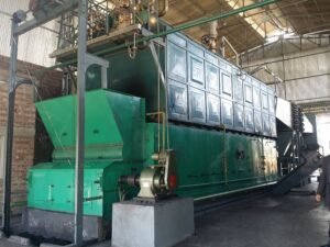
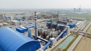
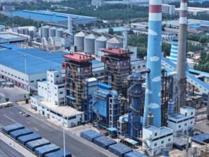
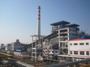
Stack temperatures running above 400°C are essentially cash leaving the building. In cement kilns, steel reheating furnaces, glass tanks, and coke ovens, exhaust gases routinely leave the process at 500–900°C — sometimes higher — carrying 30 to 50% of the fuel energy the plant already paid for. That heat dumps into atmosphere, cooling towers, or dilution air systems, driving up both fuel consumption and flue gas treatment costs. Plants that ignore this typically face a compounding problem: high energy bills, unnecessary CO₂ exposure, and — in regions with tightening emissions regulations — growing compliance risk on top of pure operating cost.
A waste heat recovery boiler (WHRB) is a heat exchanger system installed in an industrial or power plant exhaust stream that captures thermal energy from high-temperature flue gases — typically between 300°C and 1,200°C — and converts it into usable steam, hot water, or thermal fluid output, without any additional combustion. Recovery efficiency ranges from roughly 60% to 90% of available exhaust gas enthalpy, depending on inlet gas temperature, flow rate, boiler surface design, and the minimum allowable exit temperature set by downstream equipment or acid dew point constraints.
What makes WHRBs genuinely interesting from an engineering standpoint is that the “fuel” is already there — it’s a byproduct of something the plant is running anyway. The economics follow directly from that: payback periods on well-specified installations commonly land between 18 months and 4 years, depending on local energy prices, annual operating hours, and how the recovered steam or power gets used internally. But the range is wide, and the difference between a system that pays back in two years and one that underperforms for a decade almost always comes down to decisions made during selection and design — not after commissioning.
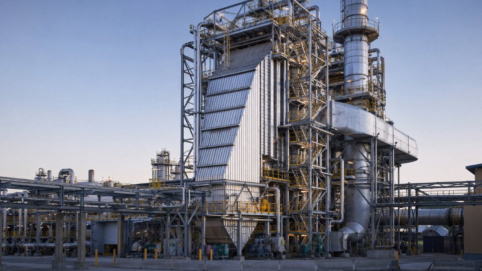
Core Working Principle: How Exhaust Gas Heat Becomes Usable Steam or Hot Water
Heat recovery sounds simple in concept — hot gas in, usable steam or hot water out. The actual engineering is more layered than that, and understanding the sequence matters a lot when you’re sizing a system or troubleshooting a performance shortfall.
The Heat Transfer Path, Zone by Zone
Flue gas enters the WHRB at the hot end, typically anywhere from 300°C on the low side (say, a diesel genset exhaust) up to 1,100°C or higher off a cement kiln or electric arc furnace. It doesn’t hit a single heat exchanger — it travels through a staged arrangement of tube bundles, each pulling enthalpy out of the gas stream as the temperature drops progressively toward the cold end.
First zone: the superheater, if the application calls for superheated steam. This sits closest to the gas inlet precisely because you need high-temperature driving force to push the steam past saturation. Next comes the evaporator — the bulk of the heat surface, where the water-steam mixture absorbs latent heat and phase change actually happens. Last is the economizer, which uses the now-cooler flue gas (often 200–350°C at this point, depending on the process) to preheat incoming feedwater before it reaches the drum. Each zone has a distinct heat duty, and the tube bundle geometry, fin density, and spacing are designed for conditions in that specific zone, not interchangeable.
Three Heat Transfer Modes — Weighting Varies by Gas Temperature
Convection dominates in the vast majority of WHRBs. Gas flows across tube bundles, boundary-layer mixing transfers heat to the tube wall, and the math is reasonably well-behaved. When gas inlet temperature climbs above roughly 900°C, radiation starts contributing meaningfully — sometimes accounting for 20–35% of total heat transfer in the first pass. At those temperatures, tube material selection and surface emissivity become real design constraints, not textbook footnotes. Conduction through the tube wall is always present but usually not the limiting resistance; it becomes significant only when you have heavy fouling, scale buildup on the water side, or unusually thick-wall tubes specified for high-pressure duty.
Drum-Type vs. Once-Through: Choosing the Right Circulation Design
Most industrial WHRBs below about 6 MPa use a natural-circulation drum design. Density difference between the steam-water mixture in the riser tubes and the cooler water in the downcomers drives circulation without a pump. The steam drum sits at the top, separating steam from water, managing blowdown to control dissolved solids, and providing a buffer volume that makes the system tolerant of load swings. It’s robust, relatively forgiving on water quality if you stay on top of treatment, and the right choice for most cement, glass, and metallurgical off-gas applications.
Forced circulation (with a circulation pump) suits tighter tube layouts and higher pressures — the 6–14 MPa range where natural density differentials weaken and you can’t rely on thermosiphon flow alone. Once-through designs eliminate the drum entirely; feedwater makes a single pass and exits as steam. That works well for compact, high-pressure systems but is less tolerant of feedwater quality variation and load transients. For most EPC projects I’ve seen in developing industrial markets, drum-type natural circulation is the default unless the pressure spec forces otherwise.
Dew-Point Corrosion: The Risk That Quietly Destroys Economizers
Exhaust gases from sulfur-bearing fuels or processes can cause rapid cold-end corrosion if economizer outlet water temperature drops below the acid dew point.True
SO₂ in flue gas combines with moisture to form sulfurous and sulfuric acid. Below roughly 130–160°C (the exact threshold depends on SO₃ concentration and moisture content), these acids condense on tube surfaces, causing accelerated electrochemical corrosion that can perforate economizer tubes within months.
This is where plants get into trouble if the WHRB is oversized or the feedwater temperature isn’t controlled. For sulfur-bearing exhaust — anything from heavy fuel oil combustion to sulfide ore smelting — keep the economizer outlet water temperature above 130–160°C. The actual dew point depends on SO₃ concentration and moisture partial pressure, so a generic number is only a starting point; you need the actual flue gas composition to set the operating floor properly. HCl in the gas (common with certain waste-derived fuels or PVC-containing materials) shifts the corrosion chemistry further and may push that temperature floor higher still.
Ignoring this during commissioning because “the gas looks clean” is a common mistake. Acid attack at the cold end is slow enough to miss in the first few months, then suddenly you’re pulling tubes.
Sizing Logic: The Energy Balance
The governing equation is straightforward:
Q_recovered = ṁ_gas × Cp_gas × (T_in − T_out)
Where Q is the recoverable heat duty, ṁ is the mass flow rate of flue gas, Cp is the specific heat (roughly 1.0–1.1 kJ/kg·K for typical combustion flue gas, varying with composition and temperature), and the temperature difference is what your heat surface area and gas-side pressure drop budget have to work with. Push T_out too low and you hit dew-point risk; leave T_out too high and you’re leaving recoverable energy on the table. The practical exit gas temperature target is usually a balance between heat recovery efficiency and corrosion margin — often landing between 150°C and 220°C depending on the fuel and steam demand.
From Q, engineers back-calculate the required heat transfer area using overall heat transfer coefficients (U-values typically in the range of 30–80 W/m²·K for gas-side convection-dominated surfaces, varying with gas velocity, fin geometry, and fouling factors). That area drives tube count, bundle dimensions, and ultimately the boiler footprint — which matters more than most people realize when you’re retrofitting into an existing plant layout.
Structural Anatomy: Key Components of a [Waste Heat Recovery Boiler](https://coalbiomassboiler.com/product/waste-heat-recovery-boiler/) and Their Engineering Roles
A WHRB is not simply a shell-and-tube heat exchanger bolted onto an exhaust stack. Each section is engineered to handle a specific temperature band, a specific fouling risk, and a specific failure mode — and specifying one component incorrectly can compromise the entire heat recovery train. Here is how the system breaks down from gas inlet to steam outlet.
Gas Inlet Duct and Expansion Joint
The inlet duct is where the harshest conditions meet the most overlooked design decisions. For flue gas entering above roughly 700°C — common in glass furnace or electric arc furnace applications — the duct interior typically requires a castable refractory lining, usually 100–200 mm thick depending on gas temperature and metal wall temperature limits. Skimping on this lining, or using a standard ceramic fiber blanket where castable is needed, leads to shell plate warping within months.
Flow distribution baffles inside the inlet transition are equally critical. Without them, the tube bundles downstream see uneven velocity profiles — hot streaks on one side, dead zones on the other — which accelerates local erosion and creates thermal fatigue in the first tube rows. In practice, most reputable designs include at least one perforated baffle plate to even out the gas front.
Expansion joints (usually corrugated metallic bellows or fabric compensators) must be sized for both axial and lateral movement. For a large cement kiln WHRB, thermal growth of the inlet duct can exceed 30–50 mm over the operating temperature range. Forget the expansion joint or undersize it, and you are putting structural stress directly into the boiler casing.
Superheater Section
The superheater sits closest to the gas inlet in a high-temperature WHRB, so tube material selection is not academic — it is a maintenance budget decision. TP304H handles well up to around 600°C metal temperature; TP347H offers better creep resistance and is preferred where flue gas contains moderate sulfur. For high-pressure steam applications above 9 MPa, T91 (9Cr-1Mo-V) is the standard choice, though it demands careful post-weld heat treatment in the field — something that gets cut during rushed erections.
The main failure modes here are high-temperature oxidation and carburization, particularly when the gas composition fluctuates (common in steel plant WHRBs where furnace charging cycles change rapidly). Steam-side flow imbalance between parallel tube circuits causes some tubes to run hotter than others; outlet headers need proper flow-control orifices to force even distribution.
Evaporator Tube Bundles
This is the core heat-transfer section, and the arrangement — membrane wall versus bare tube bundle — depends heavily on gas-side dust loading. For cement or sinter cooler applications where dust concentrations can reach 30–80 g/Nm³, a bare-tube staggered arrangement with generous tube pitch (transverse pitch/tube OD ratios of 3:1 or wider) allows ash to fall through rather than bridge between tubes and form insulating deposits. Membrane walls work well in cleaner gas streams (combined cycle, glass forehearth exhaust) where they also provide a tighter pressure envelope.
Natural circulation is standard for most industrial WHRBs up to moderate pressures (roughly up to 6–9 MPa). Forced circulation becomes necessary when the evaporator tube layout cannot provide adequate driving head — typically in compact horizontal designs or when operating at low load. The circulation ratio, usually 8:1 to 25:1 depending on pressure and geometry, needs to be verified by thermal-hydraulic calculation, not assumed.
Economizer
The economizer handles feedwater preheating from roughly 60–105°C inlet up to 100–180°C outlet, depending on steam pressure and how much heat remains in the flue gas at this downstream position. Finned tubes — low-alloy carbon steel is standard, SA-210 or equivalent — increase heat transfer area without dramatically increasing the footprint.
The critical engineering constraint here is acid dew point. For sulfur-bearing fuels or processes (sulfur content in flue gas above roughly 5–10 ppm SO₃), the feedwater inlet temperature must stay above the dew point, typically 120–150°C for moderate sulfur levels, to prevent condensation on tube surfaces. Getting this wrong means cold-end corrosion that destroys economizer tubes in 12–18 months. Soot blowers — usually wall-mounted retractable lances or rotary rake types — should be integrated into the economizer casing design at the procurement stage, not retrofitted later.
Acid dew-point corrosion is the single most common cause of economizer tube failure in WHRBs processing sulfur-bearing exhaust gases.True
SO₃ in flue gas condenses as sulfuric acid on tube surfaces when metal temperatures drop below the acid dew point, typically 120–150°C. Feedwater inlet temperature control and material selection are the primary mitigation strategies, and this failure mode is well-documented in WHRB field service records across cement and steel applications.
Steam Drum
The steam drum is the pressure vessel at the top of the natural circulation loop, and it deserves specification attention beyond just wall thickness. Internals — cyclone separators, chevron demisters, or a combination — determine steam quality. Carryover of moisture into the superheater causes erosion and, eventually, tube failures that are expensive and time-consuming to locate. Drum internals are often where budget gets squeezed; that is usually a mistake.
Chemical dosing connections (for phosphate dosing or oxygen scavenging) should be sized and located per the water treatment scheme selected — not as an afterthought. Safety valve sizing follows ASME Section I or EN 12952 depending on the export market; both have mandatory minimum relieving capacity calculations that must be documented before the vessel leaves the shop.
Auxiliary Systems
Soot blowers are not optional in dusty-gas applications. Sonic horns (typically 150–165 dB at the source) work reasonably well for light, cohesive ash; rotary rake or retractable lances are more effective for sticky or heavy deposits like those from ferroalloy furnaces. The ash hopper geometry below the tube bundles — hopper half-angle, discharge valve sizing, and whether a drag conveyor or pneumatic system is used — directly affects whether ash clears the heat transfer zones or re-entrains.
The bypass damper and diverter valve system allows the plant to route exhaust gas around the WHRB during startup, maintenance windows, or low-load periods when generating steam is not practical. Undersizing this damper — or selecting a guillotine type where a louvre type is more appropriate — creates pressure imbalance in the gas path that affects the main process. Feedwater system auxiliaries (deaerator, feedwater pumps, makeup water system) need to match the WHRB’s transient load profile, not just steady-state design capacity. Instrumentation — calibrated pressure transmitters, sheathed thermocouples at gas inlet/outlet and steam/water circuit taps, redundant drum level gauges — is what separates a plant that can optimize and troubleshoot from one that simply runs until something fails.
Industrial Application Map: Which Processes Generate Recoverable Waste Heat and at What Temperatures
Not every exhaust stream is worth chasing. Temperature level, gas volume, dust loading, and chemical aggression all determine whether a WHRB installation pencils out — or becomes a maintenance nightmare that the plant eventually bypasses. The table at the end of this section gives a consolidated reference, but the operational context behind each row matters more than the numbers alone.
Cement Plants
This is the most mature WHRB market globally, and for good reason. A dry-process kiln produces two distinct recoverable streams: preheater exit gas leaving the cyclone tower at roughly 300–400°C, and clinker cooler exhaust at 250–350°C. Neither stream is particularly clean — dust loads of 30–80 g/Nm³ are typical, and alkali compounds (K₂O, Na₂O) deposit aggressively on heat transfer surfaces. Well-designed cement WHRBs use wide-pitch bare tubes or membrane walls with soot-blower coverage on close spacing to deal with this.
The payoff is substantial. A properly integrated cement WHRB system — one covering both streams — typically generates somewhere between 30 and 40 kWh of power per tonne of clinker via a steam turbine, though the actual figure depends heavily on kiln type, clinker cooler efficiency, and local ambient temperature. A 5,000 t/day clinker line might realistically recover 6–9 MW of electrical output. Payback in regions with high grid power costs often lands in the 2–3 year range.
Steel and Non-Ferrous Metals
Electric arc furnace (EAF) off-gas is among the most challenging streams industrially — temperatures at the furnace fourth hole routinely reach 800–1,200°C, and CO content can spike above 10% by volume during the melting phase. Any WHRB on an EAF must be explosion-proof in design: the gas duct requires a dedicated CO combustion chamber or controlled dilution air system before the boiler inlet, and the whole arrangement needs pressure-relief rupture discs rated to actual transient conditions, not just steady-state estimates.
Converter gas recovery (OG systems) in basic oxygen furnaces follows a similar logic but operates on a batch cycle, which means the boiler sees wide thermal cycling. Sintering machine exhaust runs cooler, typically 250–380°C, but carries high SO₂ and fine particulate — a combination that accelerates cold-end corrosion if the economizer outlet temperature is allowed to drop below the acid dewpoint.
Glass Furnaces
Regenerative glass melting furnaces exhaust flue gas at 400–600°C, but the chemistry is hostile. Alkali vapors (particularly NaOH and KOH from the batch) deposit as sticky, low-melting-point salts on tube surfaces, and SO₂ concentrations of 500–2,000 ppm accelerate sulfation. In practice, glass WHRB installations use 310S or Alloy 625 cladding on the first tube rows, and cleaning cycles are measured in days rather than weeks. Skimping on alloy selection here leads to perforation failures within 12–18 months — a consequence I have seen more than once when procurement substituted carbon steel tubes to cut capital cost.
Petrochemical and Refinery Applications
Process furnace flue gas in refineries typically exits at 350–550°C and is relatively clean by metallurgical industry standards. The more complex application is the fluid catalytic cracking unit (FCCU), where the regenerator flue gas carries fine catalyst particles at concentrations that can exceed 200 g/Nm³ — requiring impingement baffles and large-radius bends before any finned surface. Hydrogen reformer waste gas recovery is more straightforward and commonly integrated into HRSG-type units supporting combined heat and power schemes. Steam parameters here are usually higher, 4–10 MPa superheat, feeding back into the plant’s process steam header.
Gas Turbine and Engine Exhaust
This is in many ways the cleanest application. Gas turbine exhaust typically runs 400–600°C with dust loads under 5 mg/Nm³, which allows finned tube bundles with tight pitch and higher heat transfer coefficients. HRSG-type WHRBs on gas turbines are standard equipment in combined-cycle power plants and industrial cogeneration systems. The main design variable is whether the installation is single-pressure or multi-pressure: larger turbines often justify a three-pressure HRSG (HP/IP/LP sections) to extract every viable kJ.
Municipal Solid Waste Incineration
MSW incineration is a special case. The furnace exit gas at 850–950°C means the WHRB is not just a heat recovery device — it is the primary steam generator for the plant. The corrosion environment is among the most aggressive in industrial practice: HCl concentrations of 500–1,500 mg/Nm³, heavy metals, and the dioxin re-synthesis window between 250–400°C all demand specific design responses. High-temperature corrosion on superheater tubes is controlled by limiting steam temperature (usually capped at 400°C in municipal applications), selecting Inconel or 310S for the first superheater pass, and maintaining flue gas velocity above 6 m/s to prevent fly-ash bridging.
Cement kiln WHRBs covering both preheater exit gas and clinker cooler exhaust can typically generate 30–40 kWh of electricity per tonne of clinker.True
This range is widely reported in cement industry audits and aligns with published data from multiple kiln OEMs and energy recovery project assessments; actual yield depends on kiln specific heat consumption, cooler design, and system integration quality.
Summary: Key Parameters by Process
| Process | Gas Inlet Temp (°C) | Typical Gas Volume (Nm³/h) | Dust Load (g/Nm³) | Typical Steam Parameters | Dominant Design Challenge |
|---|---|---|---|---|---|
| Cement — preheater exit | 300–400 | 100,000–400,000 | 30–80 | 1.0–3.5 MPa, sat. to lightly superheated | Alkali fouling, dust bridging |
| Cement — clinker cooler | 250–350 | 80,000–300,000 | 20–60 | 1.0–2.5 MPa | Low-grade heat, high dust |
| EAF steelmaking | 800–1,200 | 50,000–200,000 | 10–50 (post-combustion) | 1.6–4.0 MPa | CO explosion risk, thermal cycling |
| Sintering machine | 250–380 | 200,000–600,000 | 5–30 | 1.0–2.5 MPa | SO₂ cold-end corrosion |
| Glass furnace | 400–600 | 30,000–120,000 | 2–15 | 1.6–4.0 MPa | Alkali/sulfate corrosion, frequent cleaning |
| Refinery / FCCU | 350–550 | 50,000–300,000 | 50–200 (FCCU) | 4.0–10.0 MPa, superheated | Catalyst erosion, high-pressure design |
| Gas turbine / engine | 400–600 | 100,000–1,000,000+ | 5 g/Nm³) | Bare tubes | 30–60 W/(m²·K) |
| Moderately clean gas | Bare or sparse fin | 50–90 W/(m²·K) | |||
| Clean gas (<1 g/Nm³) | Finned tubes | 60–120 W/(m²·K) |
Fouling factor selection is where engineers often get optimistic. In a clean natural gas turbine exhaust, a fouling factor of 0.0002 m²·K/W on the gas side is reasonable. In a steel plant with sticky, sulfur-laden dust, you need 0.0005 or higher, which can add 20–35% to your calculated heat surface area. Skimping here means the unit runs short of its design output within six to eighteen months as fouling builds up.
Material Selection by Temperature Zone
Carbon steel (SA-210 A1 or equivalent) handles tube metal temperatures up to roughly 400°C without issue and is the economic choice for economizer and low-pressure evaporator sections. T11 and T22 chromium-molybdenum alloys cover the 400–550°C range typical of medium-pressure superheaters. Above 550°C — which you’ll encounter in high-pressure superheaters for power applications — T91 or T92 is the right call; they offer significantly better creep resistance and are widely specified in modern units.
Aggressive chemical environments, particularly high-HCl conditions like those in waste incineration, push you into austenitic stainless territory: 304H or 347H, sometimes even Alloy 625 cladding on tube sheets. The cost premium is real, but so is the corrosion rate on standard carbon steel exposed to HCl above the dew point.
Standards and Certification
Export projects need this resolved at RFQ stage, not after order placement. ASME Section I governs pressure part fabrication for U.S. and most international projects, and units carrying the ASME ‘S’ stamp demonstrate third-party inspection compliance. EN 12952 applies in Europe. GB/T 16507 is the Chinese national standard — relevant because a large share of global WHRB manufacturing happens in China, and buyers specifying ASME or EN compliance need to confirm the manufacturer holds the actual stamp, not just claims it. Taishan Group units manufactured for international EPC projects carry the ASME ‘S’ stamp, which matters when the end-client or their insurance underwriter requires it.
Have all of these parameters documented before you issue the inquiry. A proper technical datasheet takes a few hours to prepare. Chasing missing information through three rounds of RFQ clarification takes weeks.
Efficiency, Energy Recovery, and Emissions Impact: Quantifying the Business Case
Before a factory owner signs off on WHRB capital expenditure, someone in the room needs to put real numbers on the table — not marketing claims, but engineering-grade estimates with honest dependencies. Here is how to build that case.
Thermal Efficiency: What the Numbers Actually Mean
WHRB thermal efficiency is defined as Q_steam ÷ Q_available_in_exhaust × 100%. For a well-designed unit with a properly sized economizer, expect 70–88%. Where you land in that range depends mainly on three things: the pinch-point temperature difference, the inlet gas temperature, and how aggressively the economizer is sized.
Pinch-point temperature difference — the minimum approach temperature between flue gas and the water/steam side at the evaporator outlet — typically runs 15–30°C in industrial practice. Push it below 15°C and you are fighting physics: heat transfer area grows exponentially, capital cost spikes, and the unit becomes sensitive to any shift in gas flow. Set it above 30°C and you are leaving recoverable energy in the stack. Most experienced designers settle around 18–22°C as the practical sweet spot, though plants with highly variable gas flows often need to stay toward the upper end to avoid steaming problems at part load.
Fuel and CO₂ Savings: A Worked Cement Plant Example
Take a dry-process cement line generating preheater exhaust at roughly 280–320°C and 150,000 Nm³/h. A properly specified WHRB on that stream can produce approximately 16–20 t/h of saturated or slightly superheated steam at 1.4–1.6 MPa — call it 18 t/h as a mid-estimate. That steam directly displaces what would otherwise be generated by coal-fired auxiliary boilers. At a coal consumption rate of around 750–800 kg of steam per tonne of standard coal, you are offsetting something in the range of 12–15 tonnes of coal per day, depending on auxiliary boiler efficiency and steam conditions.
The CO₂ arithmetic follows: coal combustion at roughly 2.5–2.6 kg CO₂/kg coal puts the avoided emissions at 25–35 kg CO₂ per tonne of clinker produced — a figure that sits well within what CDM and Gold Standard methodologies will credit.
A 150,000 Nm³/h cement preheater WHRB installation can displace 12–15 tonnes of coal per day in auxiliary boilersTrue
This estimate is consistent with standard enthalpy calculations for 280–320°C exhaust gas at that flow volume, assuming WHRB thermal efficiency of 75–82% and auxiliary boiler efficiency of 80–85%. Actual figures vary with gas composition, moisture content, and steam pressure specified.
Power Generation: WHRB Paired with a Steam Turbine Generator
When the recovered steam feeds a back-pressure or condensing steam turbine generator (STG) rather than a process header, you are looking at electrical output. For a mid-size cement line — 2,500 to 5,000 tonnes of clinker per day — combined AQC (air quenching cooler) and SP (suspension preheater) WHRB systems typically deliver 5–15 MW of installed capacity. Specific power generation commonly falls in the 30–45 kWh per tonne of clinker range, depending on gas temperatures, turbine efficiency, and whether the plant runs a condensing or back-pressure cycle.
That electricity offset matters. At USD 0.08–0.12/kWh, a 10 MW installation running 8,000 hours per year generates USD 6.4–9.6 million in avoided electricity cost annually. Capital cost for a complete WHRB-STG system typically runs USD 600–1,100/kW of recovered electrical output, depending on scope, local civil work, and equipment specification. Simple payback at those numbers lands somewhere between 2 and 4 years — longer if fuel prices are soft, shorter if the plant is paying peak industrial tariffs.
Emissions: Beyond the Boiler Itself
A WHRB does not combust anything. That is an underappreciated point. Eliminating the need for supplementary coal-fired steam generation directly removes SO₂, NOₓ, and particulate sources from the site inventory. The WHRB does handle dusty gas — cement preheater exit gas can carry 40–80 g/Nm³ of dust — so the gas-side outlet must integrate with an ESP or bag filter. Properly specified, dust emissions at the WHRB stack outlet can be maintained below 30 mg/Nm³, which meets most regional industrial standards.
Carbon Credit Value: Real but Variable
Verified emission reductions under Gold Standard or CDM project methodologies typically value at USD 8–25 per tonne of CO₂ avoided — the wide range reflects market conditions, vintage, and whether the credits are sold spot or under long-term offtake. For a cement plant avoiding 25,000–40,000 tonnes of CO₂ annually, that adds USD 200,000–1,000,000/year of potential carbon revenue on top of the direct fuel and electricity savings. Whether that revenue materializes depends on whether the project is properly registered and the plant has the operational documentation to support MRV (monitoring, reporting, and verification). Do not count it as guaranteed in the initial business case, but it is worth structuring the project to capture it.
Operation, Maintenance, and Common Failure Modes in [Waste Heat Recovery Boilers](https://coalbiomassboiler.com/product/waste-heat-recovery-boiler/)
Running a WHRB is not like running a fired boiler. There’s no combustion to control, but the heat source — a cement kiln, an electric arc furnace, a glass tank — is often dirtier, more variable, and less forgiving than a burner flame. The failure modes are different, the startup logic is different, and maintenance teams trained on conventional package boilers sometimes miss the details that matter most.
Startup and Shutdown Procedures
Cold startup is where thermal stress damage accumulates quietly over months before it shows up as a cracked drum or a leaking ligament. The standard practice is to limit temperature ramp rate to under 50°C per hour on the steam drum — some thick-walled drums on high-pressure units (say, above 4 MPa) are restricted to 30°C/hour by the vessel design. The bypass damper is not optional here: it must divert full process gas around the WHRB until drum pressure builds to at least 30% of design pressure, which gives the metal mass time to equalize temperature before the full gas load hits the tube bundle.
Shutdown sequence matters just as much. You close the gas inlet damper before stopping feedwater, not after. Trapping hot gas in a dry or low-water drum is how you get oxide scale spalling and, eventually, tube failures that look mysterious six months later.
Routine Maintenance Schedule
Daily checks are non-negotiable: drum water level (both gauge glass and transmitter, cross-verified), steam pressure against operating setpoint, gas inlet and outlet temperatures against baseline, and soot blower operation confirmed. A rising gas-side pressure drop with stable gas flow usually means fouling before any other alarm trips — catching it daily saves an unplanned outage.
Weekly tasks include bottom blowdown to remove dissolved solids concentrate from the drum, and a manual lift test on at least one safety valve. Monthly, walk the tube lanes and inspect gas-inlet-side tubes and bends with a flashlight and mirror — erosion shows up as a bright, polished surface on the upstream face of the tube before wall thinning becomes critical.
Annual shutdown should include a full hydrostatic pressure test per ASME Section I or GB/T 16507, whichever governs your installation, plus a complete internal inspection with borescope on any tube rows you cannot reach manually. Weld seams on the drum and headers deserve particular attention after the first three to five years of service.
Tube Erosion
In cement and steel plant applications, ash particle loadings can reach 50–150 g/Nm³ and particle velocities at the tube inlet can easily exceed safe limits if the inlet duct is undersized or poorly baffled. Erosion concentrates at tube bends and the gas-inlet-facing side of the first two or three tube rows. The practical fixes: erosion shields (replaceable ceramic or hard-facing plates), specifying increased wall thickness on those rows during procurement (a 20–30% thickness premium on inlet tubes is worth asking for), and targeting gas velocity below roughly 12 m/s through the bundle.
Keeping flue gas velocity below 12 m/s through the tube bundle significantly reduces ash erosion on inlet-side tubes in high-dust WHRB applications.True
Erosion rate by particle impingement is approximately proportional to velocity squared to the third power; reducing velocity from 15 m/s to 11 m/s can cut erosion rate by roughly 40–50%, a relationship well-established in heat exchanger engineering practice.
Acid Dew-Point Corrosion at the Cold End
Any process gas containing SO₂ — sulfur-bearing fuels, non-ferrous smelting, certain waste streams — creates sulfuric acid vapor that condenses on economizer tubes when their surface temperature falls below roughly 130–150°C, depending on SO₃ concentration. The corroded tube looks pitted and orange-brown, and it often fails from the outside in rather than the inside out, which confuses inspection teams expecting waterside damage.
The standard engineering response is a feedwater bypass valve that recirculates hot water from the economizer outlet back to the inlet, maintaining tube wall temperature above the dew point. Setting that bypass correctly — usually targeting 140°C minimum surface temperature — is a commissioning task that often gets skipped and then causes economizer replacement within two or three years.
Tube Fouling and Blockage
Glass furnace and cement kiln gases carry alkali sulfates and chlorides that form sticky, low-melting-point deposits on tube surfaces. Unlike dry fly ash, these deposits don’t respond well to steam soot blowers alone. Online sonic soot blowing — acoustic horns mounted in the gas lanes — works considerably better for sticky deposits and should run on a timed cycle, typically every two to four hours. If pressure drop across the bundle climbs above roughly 150% of clean baseline despite online cleaning, plan a water wash during the next planned outage. Do not delay it: tube lane blockage forces higher gas velocity through the remaining open lanes, accelerating erosion in those areas specifically.
Steam Drum Level Upsets
Process furnaces don’t run at steady state. A load swing at the glass tank or kiln pushes a pulse of hotter-than-normal gas through the WHRB, which causes steam generation to spike and drum level to swell — then shrink as the pulse passes. A single-element level control (level only) will chase the swell and flood the drum, then underfill it on the shrink. Three-element feedwater control, which measures steam flow, feedwater flow, and drum level simultaneously, handles these transients without hunting. In practice, plants that try to save cost by using single-element control on variable-load WHRBs end up with carryover events and wet steam in the process header within the first year.
Critical Spare Parts to Stock On-Site
Superheater tube sections (cut to the most common bend radius in your unit), boiler feed pump mechanical seals, soot blower lances (they erode from the inside out in dusty gas), safety valve internals including springs and seat discs, level gauge glass sets, and the bypass damper actuator — pneumatic or electric, whichever your installation uses. Lead times on actuators and safety valve trim from OEM suppliers can run eight to sixteen weeks depending on pressure class and origin. Stocking these on-site is cheap insurance against a four-month outage waiting for parts.
Taishan Group WHRB Product Range, Manufacturing Capability, and EPC Project Delivery
The product range covers what most industrial projects actually need. Taishan Group manufactures waste heat recovery boilers from 1 t/h — suitable for small kilns, incinerators, or engine exhausts — up to 200+ t/h for large-scale cement clinker lines, steel reheat furnaces, and combined-cycle gas turbine heat recovery applications. Pressure classes span from 0.4 MPa saturated steam (low-pressure process heating, drying, or absorption chiller duty) through intermediate ranges around 3.8–6.3 MPa (industrial power generation) up to 13.7 MPa / 540°C for high-pressure, high-temperature power plant configurations where the recovered steam feeds a condensing turbine. That range matters in practice because a cement plant recovering heat from a 950°C preheater exit gas has fundamentally different pressure vessel requirements than a gas turbine HRSG running at 560°C exhaust — and one design envelope does not fit both.
Certifications That Actually Affect Project Approval
Holding the right stamps is not a formality — it determines whether a unit clears customs, passes third-party inspection, or satisfies an EPC contractor’s insurance requirements. Taishan carries the ASME ‘S’ Stamp for power boilers, which means pressure parts are manufactured and documented to ASME Section I requirements and are acceptable for projects in North America, Southeast Asia, and any market that references ASME as its technical standard. CE marking covers EU-destined units under the Pressure Equipment Directive (PED 2014/68/EU). The China Special Equipment Manufacturing License (Class A) is mandatory under GB/T regulations for domestic supply and is typically reviewed by overseas buyers as evidence of a regulated quality system. ISO 9001 certification governs the quality management system across design, procurement, fabrication, and delivery.
Taishan Group holds ASME 'S' Stamp certification for power boiler manufacturingTrue
The ASME 'S' Stamp is issued by the American Society of Mechanical Engineers following a formal survey of manufacturing facilities, documentation systems, and quality controls. It authorizes the manufacturer to produce power boilers to ASME Section I and apply the official code stamp to pressure parts.
For multi-standard projects — which come up more often than people expect, particularly in Southeast Asia and the Middle East where local codes, EPC contractor specs, and end-user insurance requirements can all point at different standards simultaneously — Taishan’s engineering team can design and document a single unit against ASME Section I, EN 12952 (water tube boilers), and GB/T 16507 in parallel. That is not trivial; the allowable stresses, inspection categories, and weld joint efficiency factors differ between codes, and the conservative envelope has to be identified component by component.
In-House Engineering Depth
Thermal design is done in-house, not outsourced. Gas-side flow distribution is modeled using CFD before any tube bank layout is finalized — this matters especially on units with high dust loading (cement or steel applications typically carry 20–80 g/Nm³ particulate) because uneven flow causes localized tube erosion within 12–18 months of operation if the inlet duct geometry is wrong. Drum and header designs go through FEA stress analysis, particularly for units above 6 MPa where thermal fatigue at nozzle connections is a documented failure mode across the industry.
Auxiliary Equipment and Balance of Plant
A WHRB delivered as a bare pressure vessel still requires deaerators, feedwater pumps, chemical dosing, soot blowers, steam separators, and a control system before it runs. Taishan supplies all of it. The control scope can be a standalone PLC panel or a full DCS integration, depending on whether the customer is connecting to an existing plant DCS or building a new control room. Gas cleaning equipment — bag filters or electrostatic precipitators — is included where the process requires particulate removal upstream of the boiler or at the stack. Single-source supply reduces interface risk, which on EPC projects often turns out to be where schedule slippage actually originates.
EPC Delivery and Overseas Project Execution
Taishan has executed turnkey WHRB projects across Southeast Asia, the Middle East, and Africa, covering civil foundation design, equipment supply, erection supervision, commissioning, and operator training. The erection supervision model — where Taishan engineers are on-site during installation rather than just shipping drawings — reflects a practical reality: local contractors unfamiliar with large-diameter drum alignment or refractory lining sequences need hands-on guidance, not a PDF. Commissioning includes cold hydrostatic testing at 1.5× design pressure, hot functional runs, and performance verification against guaranteed steam output and gas-side pressure drop. O&M contract options are available for clients who want performance guarantees extended into the operating phase, which is increasingly requested by project finance lenders on independent power projects.
All pressure-part materials carry mill test certificates traceable to the heat number. Circumferential welds on drums and headers receive 100% radiographic testing as standard; fillet welds on tube-to-header joints are inspected by magnetic particle or liquid penetrant methods per code requirements. Third-party inspection by Bureau Veritas, SGS, or TÜV Rheinland can be coordinated at the client’s request — and in practice, most export projects above roughly 10 t/h capacity end up requiring it anyway, either by the EPC contractor or the end-user’s lender.
Frequently Asked Questions About Waste Heat Recovery Boilers
Engineers and plant owners ask us variations of the same questions repeatedly — usually during feasibility, sometimes after a poorly specified unit has already caused grief. These answers are meant to cut through the generic and give you something actionable.
What is the minimum exhaust gas temperature to make a WHRB economically viable?
The practical floor is around 250°C for low-pressure saturated steam production, but even that depends heavily on flue gas volume and the value of the recovered energy at your site. A cement preheater exit at 320°C with 80,000 Nm³/h of gas flow is a strong candidate. A 260°C stream from a small oven handling 8,000 Nm³/h probably isn’t — the heat exchanger surface area required versus the recoverable energy rarely closes.
Below 250°C you’re usually better served by a direct economizer feeding boiler feedwater preheat, or an organic Rankine cycle (ORC) system if power generation is the goal. ORC handles low-grade heat more efficiently than a steam cycle in that range, though capital cost and complexity are higher.
A flue gas inlet temperature below 200°C rarely justifies a conventional steam-based WHRB on economic grounds alone.True
At such temperatures, the log-mean temperature difference driving heat transfer is too small relative to the required surface area; heat exchanger costs typically outweigh the recovered energy value within any reasonable payback horizon unless the gas volume is exceptionally large.
Can a WHRB function properly when the upstream process runs at variable load?
Yes — but only if the design accounts for it from the start. A bypass damper on the gas inlet is non-negotiable; when process load drops sharply, you need to divert gas around the boiler to avoid thermal shock and to protect the drum water level. A variable-speed feedwater pump is equally important — fixed-speed pumps fighting a sliding load create constant control headaches and can cause low-water trips at the worst moments.
Turndown to roughly 30% of rated capacity is achievable with proper control logic. Below that, you’re usually operating in a regime where steam quality degrades or the economizer risks steaming, which is a whole separate problem. In practice, plants running highly variable processes — electric arc furnaces, batch glass tanks — often pair the WHRB with an accumulator or a small supplementary-fired steam buffer. It’s an extra line item, but the alternative is a boiler that trips every time the upstream operator adjusts the furnace.
How is a WHRB different from an HRSG?
The terms get conflated constantly, including by vendors who should know better. An HRSG — heat recovery steam generator — is technically a subset of WHRB, but it’s designed specifically around gas turbine exhaust: relatively clean gas, well-defined temperature profiles, and often supplementary burners to boost steam output when the turbine runs at part load. Gas turbine exhaust is about as clean an inlet as you’ll ever get.
Industrial WHRBs for cement kilns, steel reheating furnaces, or waste incinerators deal with a completely different reality: high dust loading (sometimes 50–80 g/Nm³), sticky or corrosive compounds (alkali chlorides, sulfates, heavy metals depending on the process), and inlet temperatures that can swing 200°C in under an hour. The tube arrangement, cleaning systems, gas velocity limits, and material selection are all fundamentally different. Specifying an HRSG-grade unit for a cement application is a reliable route to plugged convection passes and accelerated corrosion.
What steam parameters can a WHRB realistically deliver?
The range is wider than most people expect. On the low end, a glass or food-processing application might need nothing more than 0.4 MPa saturated steam for direct process heating. On the high end, large cement or steel WHRBs feeding condensing turbines for captive power generation operate at 8.0–13.7 MPa with superheated steam at 450–540°C. The ceiling isn’t really the boiler design — it’s the available exhaust temperature and whether the economics justify the incremental surface area to reach higher superheat.
A 450°C kiln exit gas can realistically support 1.6–3.8 MPa steam with moderate superheat. Push for 8 MPa from the same source and you’ll be installing a lot of expensive surface area to squeeze out diminishing returns.
How long does installation and commissioning take?
A pre-fabricated modular unit in the 20–50 t/h range — shop-assembled sections, shipped to site — typically runs 4 to 8 months from order to first steam, assuming civil foundations are prepared on schedule. That last caveat matters: foundation delays are the single most common cause of project overrun, in my experience.
Large custom units above 100 t/h, particularly for steel or cement with complex ductwork and multi-stage heat recovery, realistically need 10 to 14 months. Anyone quoting you 3 months for a 120 t/h unit is either misrepresenting the scope or planning to cut corners on testing.
Does a WHRB require a licensed boiler operator?
Yes, universally. Any steam-generating pressure vessel operating above 0.1 MPa falls under licensed operator requirements in virtually every industrial jurisdiction — whether you’re in Southeast Asia, the Middle East, or Europe. The specific certification tier depends on operating pressure and capacity, and requirements vary by country, but the baseline obligation is consistent.
Taishan Group provides operator training as part of commissioning handover and can supply remote monitoring systems that allow off-site performance oversight — useful for clients running facilities in regions where experienced local operators are hard to retain.
What is the realistic service life, and what shortens it?
Design life for a properly specified and maintained WHRB is 25 to 30 years. What actually determines whether you reach that number comes down to three things: feedwater quality, gas-side corrosion management, and whether anyone follows the maintenance schedule.
Feedwater hardness and dissolved oxygen are the dominant tube-side killers. Silica scaling above 0.2 mg/L starts fouling superheater tubes quietly until efficiency drops noticeably — by the time operators notice, you’ve often already lost meaningful tube wall thickness to under-deposit corrosion. On the gas side, dew-point corrosion in the cold-end economizer is the typical failure initiator, especially in processes with sulfur-bearing fuels or waste streams. Managing economizer outlet temperature above the acid dew point — usually 130–160°C depending on SO₃ concentration — extends cold-end tube life substantially.
Plants that treat water treatment as optional and defer soot-blower maintenance routinely see significant component failures well before the 15-year mark.
Can Taishan Group supply the boiler only, or also manage the full EPC scope?
Both. Equipment-only supply — with or without an on-site supervision team during installation — works well for EPC contractors or owner-operators with their own engineering resources. Full EPC turnkey scope covers civil works, pressure-part erection, piping, electrical, DCS control system, grid connection for power generation projects, and commissioning through performance testing. The right choice depends on what your in-country contractor base can handle and whether you want a single point of responsibility for the whole system. For projects in regions with limited local boiler engineering capability, the turnkey route typically reduces risk more than it adds cost.
References
Waste Heat Recovery Basics — U.S. Department of Energy
How Gas Turbine Power Plants Work — U.S. Department of Energy
Waste Heat to Power Systems — U.S. Environmental Protection Agency
CHP Technologies — U.S. Environmental Protection Agency
Most Combined-Cycle Power Plants Employ Two Combustion Turbines with One Steam Turbine — U.S. Energy Information Administration
Most Combined-Cycle Power Plants Have Duct Burners That Add Energy to Turbine Exhaust — U.S. Energy Information Administration
Combined Heat and Power Technology Fact Sheet: Gas Turbines — U.S. Department of Energy Better Buildings Solution Center
Improving Process Heating System Performance: A Sourcebook for Industry — U.S. Department of Energy
Using Waste Heat for External Processes — National Laboratory of the Rockies
Introduction to Steam Distribution — Spirax Sarco