Specify the wrong waste heat recovery boiler for your flue gas chemistry and the consequences stack up fast — acid corrosion eats through economizer tubes in under two years, fouling from sticky ash cuts heat transfer coefficients by 30–40%, and a unit sized without accounting for fuel sulfur content or particulate loading will either trip on high backpressure or limp along well below its rated steam output. That’s not a maintenance problem; it’s a capital write-off dressed as an operating cost.
Fuel type and combustion characteristics directly determine every critical design parameter of a waste heat recovery boiler — flue gas volume (typically 10,000 to 500,000 Nm³/h depending on process scale), inlet temperature (300°C to over 1,100°C in some furnace off-gas applications), sulfur and particulate loading, and dew-point risk. Fuels carrying more than roughly 1% sulfur by weight demand that all gas-side metal surfaces stay above 130°C–160°C to stay out of the acid condensation zone. Get that wrong and no amount of good tube metallurgy saves you.
What makes this genuinely difficult is that most plants aren’t running one clean, well-characterized fuel stream. Cement kilns swing between petcoke and coal blends mid-campaign. Glass furnaces shift fuel oil ratios seasonally. Waste-to-energy lines accept whatever the municipality delivers that week. The boiler that handles all of that without corroding, plugging, or dropping thermal efficiency below 75% doesn’t come from a catalog — it comes from understanding exactly how combustion behavior translates into mechanical and thermal design choices, tube by tube.
Coal Combustion Exhaust: High Dust Loading, Ash Fouling, and Acid Dew-Point Management in WHRBs
Coal flue gas is, bluntly, the most punishing environment a waste heat recovery boiler will ever face. Temperature alone doesn’t tell the story — it’s the combination of abrasive fly ash, corrosive sulfur species, and sticky alkali deposits that forces designers to make choices they wouldn’t touch with any other fuel.
What You’re Actually Dealing With: The Flue Gas Characterization
Fly-ash concentrations in coal combustion exhaust typically run 20–80 g/Nm³, depending heavily on coal rank, combustion technology, and whether an upstream cyclone or ESP is already pulling solids out. Bituminous coals from high-ash sources — parts of South Africa, India, or China’s northwest — will push toward the upper end of that band. SO₂ concentrations land between 1,000 and 5,000 mg/Nm³ depending on sulfur content in the fuel; anything above roughly 1% S by weight puts you squarely in high-sulfur territory where the acid dew-point becomes a design constraint, not just a footnote. NOₓ typically comes in at 400–900 mg/Nm³ depending on combustion temperature and excess-air ratio. Inlet temperatures after the primary furnace usually fall in the 280°C–650°C range — the lower end is common in tail-end recovery applications like cement kilns or power plant economizer bypass; the higher end appears when the WHRB sits close behind a combustion chamber without an intervening cooler.
Acid Dew-Point: The Constraint That Reshapes the Economizer
Sulfuric acid vapor condenses on metal surfaces somewhere between 130°C and 160°C — the exact onset temperature rises with SO₃ concentration and drops with lower sulfur content in the flue gas. In practice, you cannot simply let your economizer tail-end tube-wall temperatures fall below that threshold, because the resulting sulfuric acid condensate will eat through carbon steel in a matter of months. The fix is a combination of minimum feedwater inlet temperature control (often 105°C–120°C minimum, achieved by recirculating a portion of feedwater or using a dedicated preheat loop), and, in high-sulfur cases, swapping the last economizer rows to 409 or 304 stainless steel — or in very aggressive conditions, to enamel-coated tubes. This costs more upfront. It costs far more when you’re replacing a corroded economizer bundle after 18 months.
Tube Arrangement: Giving Ash Somewhere to Go
For high-dust coal flue gas, the standard finned-tube arrangement used in gas-fired WHRBs is essentially off the table. Fins trap ash, blind the surface, and within weeks you’re looking at severe fouling and a thermal performance cliff. The workable options are bare horizontal tubes with wide transverse pitch — a ratio of S₁/d ≥ 3.0 is the usual floor, with some designs pushing to 3.5 for particularly sticky or coarse ash — or membrane-wall panels in the higher-temperature superheater zone, which seal the casing and allow proper sootblowing without gas bypass leaks.
Sootblowing strategy matters enormously. Two-stage sootblowing — steam-lance or retractable blowers in the convection bank, acoustic sootblowers on the economizer — is the practical standard for dust loads above roughly 25 g/Nm³. Single-stage acoustic-only systems underperform when the ash is dense or has any sintering tendency. Online dust evacuation hoppers with pneumatic or screw conveyors should be sized for continuous removal at peak dust rates, not average rates. Plugged hoppers are a very common cause of unplanned outages in coal-exhaust WHRBs — usually because the hopper was undersized to save capital.
Material Selection by Temperature Zone
The zone-by-zone logic is fairly well established, though the boundaries shift depending on steam conditions:
| Zone | Typical Metal Temp | Material | Notes |
|---|---|---|---|
| Superheater (high-temp) | 420°C–580°C | T11, T22 (Cr-Mo alloys) | Oxidation and creep resistance |
| Evaporator / generating bank | 280°C–420°C | SA-210 Gr. A1 / C carbon steel | Standard workhorse |
| Economizer (mid-section) | 180°C–280°C | SA-210 carbon steel | Verify wall temp > dew point |
| Economizer tail-end (high-S coal) | 130°C–180°C | 409 SS or enamel-coated | Non-negotiable with >1% S fuel |
In coal-exhaust WHRBs burning fuel with >1% sulfur, the last economizer rows must be built from corrosion-resistant alloy or coated steel to avoid acid condensate damage.True
Sulfuric acid vapor condensation onset at 130°C–160°C causes rapid corrosive attack on carbon steel; using 409 stainless or enamel-coated tubes in tail-end economizer sections is standard industry practice for high-sulfur coal applications.
CFB Integration and Bed-Material Carryover
When the WHRB is installed at the cyclone exit of a CFB boiler — capturing residual heat from the tail-end flue gas at typically 850°C–900°C dropping to 280°C–350°C — there’s an additional erosion mechanism that doesn’t show up in conventional pulverized-coal setups. Fine bed material (usually silica sand or limestone, 50–300 µm) carries through the cyclone at concentrations that can reach 5–15 g/Nm³ even after the primary separator. These particles are harder and more angular than fly ash, and they hit tube bends and leading-edge tubes at velocities that cause measurable material loss. Tube shields or ceramic wear tiles on the first two tube rows, and gas velocity limits below about 10–12 m/s in erosion-prone zones, are standard mitigations. In my experience, plants that skip the tube shields on budget grounds typically regret it around the 18–24 month mark.
A Realistic Design Benchmark
Consider a 60 t/h WHRB positioned downstream of a coal-fired cement kiln preheater tower: inlet gas temperature 420°C, flue gas volume roughly 180,000 Nm³/h, dust load measured at 35 g/Nm³, sulfur content moderate at around 0.8% (which still warrants dew-point attention). Steam output specification is 3.82 MPa / 450°C superheated steam. The design solution in this kind of project typically includes a membrane-wall superheater section with T22 tubes, a bare-tube generating bank at S₁/d = 3.2, two-stage sootblowing (retractable steam blowers in the bank, acoustic units on the economizer), and a continuous ash hopper with screw conveyors sized for 150% of calculated peak dust accumulation rate. Economizer inlet feedwater is maintained above 115°C via recirculation. That combination keeps the unit running at 86%–89% thermal recovery efficiency across the operating range without chronic fouling outages — which is the actual benchmark that matters on a real plant schedule.
Oil and Gas Turbine/Engine Exhaust: Clean but High-Temperature Heat Recovery Demands Precise Surface Area Sizing
Gas turbine exhaust is, in one sense, the dream flue gas stream for a WHRB designer: no ash, no sulfur corrosion risk in most applications, no slagging. But “clean” doesn’t mean “simple.” The thermal density of a gas turbine exhaust stream — 450°C–560°C at the HRSG inlet for a simple-cycle machine, or 380°C–480°C behind a combined-cycle configuration — combined with very high volumetric flow rates (typically 50,000 to 300,000 Nm³/h per unit, depending on turbine class and ambient conditions) means that surface area sizing is where most design errors happen. Get the pinch point wrong by even 5°C–8°C, and you’re either leaving 10%–15% of recoverable heat on the table or you’ve overdesigned with capital cost that never pays back.
The oxygen content of turbine exhaust is worth dwelling on. At 14%–16% O₂ by volume, you have a hot, oxygen-rich duct that essentially behaves like a low-velocity furnace atmosphere. That opens the door to supplementary firing — duct burners installed upstream of the HRSG modules that burn additional natural gas directly into the exhaust stream, no separate combustion chamber needed. In practice, a well-designed supplementary firing system can lift steam output by 30%–80% above the unfired case, which is enormously attractive when the plant has peak steam demand that doesn’t line up with turbine load. The design implication is that the HRSG casing and transition ductwork must be rated for the higher peak temperatures post-burner (sometimes reaching 800°C–900°C locally), and module sequencing — superheater position, evaporator staging, economiser placement — gets recalculated for two operating modes: unfired and full-fired. A casing designed only for unfired conditions has failed in service when supplementary firing is added later, usually at a refractory lining or expansion joint.
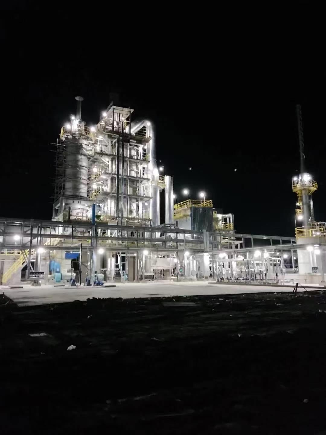
Because the gas is clean, finned-tube heat transfer surfaces are practical here in a way they simply aren’t behind coal or biomass burners. Serrated spiral fins or solid spiral fins — fin heights typically 10–20 mm, densities of 3–6 fins per inch — multiply the external surface area per tube dramatically, reducing the overall tube count and keeping the HRSG footprint manageable. In a fouling-prone gas stream, those fins would pack with deposits within months. In clean gas turbine exhaust, a well-specified fin geometry with proper material selection (carbon steel up to roughly 400°C gas temperature, alloyed materials for hotter zones) can run for years between inspections. The catch is manufacturing quality: poorly welded fin-to-tube bonds create hot spots and accelerate fatigue at cycling duty, which is increasingly common as gas turbines follow grid load.
Multi-pressure configurations — single, dual, or triple pressure — are dictated by where the turbine exhaust temperature profile intersects the steam end-use requirements. A single-pressure HRSG is usually sufficient behind smaller turbines (under roughly 20 MW) or where low-pressure process steam is the only product. Dual-pressure becomes worthwhile when you want to maximise heat extraction across a wider temperature range; the LP evaporator and economiser recover heat that would otherwise exit the stack. Triple-pressure is reserved for large combined-cycle power applications where even marginal efficiency gains translate to meaningful electricity output — the added piping complexity and controls overhead rarely justify the cost at anything below 100+ MW turbine capacity.
Reciprocating gas engines are a different animal. Exhaust flow rates are much lower — 5,000–30,000 Nm³/h per engine — and temperatures run 380°C–480°C, similar to combined-cycle turbine exhaust but with pulsating flow that stresses tube connections differently than the steady flow of a turbine. The real economic argument here is CHP: jacket-water heat recovery running in parallel with the exhaust WHRB can push overall fuel utilisation from a typical ~38%–42% electrical efficiency to 75%–85% total energy utilisation. That’s not a marketing claim; it’s straightforward thermodynamics, and it changes the payback calculation completely for any plant with year-round heat demand.
SCR catalyst beds integrated into the WHRB gas path require a flue gas temperature window of 300°C–420°C for acceptable NOₓ conversion efficiency.True
Vanadia-titania SCR catalysts operate reliably in this range; below ~290°C conversion drops sharply and ammonium bisulfate can foul catalyst pores, while above ~430°C the catalyst sinters and degrades. This is why SCR positioning within the HRSG module sequence is not arbitrary — it must align with the temperature profile of the specific gas path design.
Where local emission regulations require NOₓ below 50 mg/Nm³ — increasingly common in Southeast Asia, the EU, and parts of the Middle East — an SCR unit needs to be integrated directly into the WHRB gas path. This is not something you retrofit easily. The catalyst bed must sit in a section of the HRSG where flue gas temperature holds between 300°C and 420°C; too cold and the catalyst underperforms and fouls with ammonium salts, too hot and catalyst life collapses. That temperature window has to be confirmed against both minimum and maximum load conditions, because a turbine running at 60% load produces a noticeably different temperature profile than at full load. Ammonia injection grids and flow uniformity baffles add to the ductwork length, which affects the overall HRSG footprint. Plan for this from the start, not after the civil foundation is poured.
Biomass and Municipal Solid Waste Incineration: Corrosive Chlorine, Alkali Fouling, and Superheater Temperature Limits
Biomass and MSW incineration exhaust is, in my experience, the most punishing flue gas environment a WHRB designer will encounter. It is not simply “dirty” in the way coal ash is dirty. The chemistry is actively destructive — chlorine compounds, alkali vapors, and heavy metals work together in ways that will eat through a conventionally designed superheater in under two years if the tube material and operating temperature are chosen carelessly.
What Is Actually in the Gas
HCl concentrations in MSW flue gas typically run 200–2,000 mg/Nm³, depending heavily on the waste stream composition — PVC content in the municipal waste matters a great deal here. Biomass from agricultural residues (rice husk, straw, bagasse) sits toward the lower end, while mixed municipal waste with plastics can spike toward the upper boundary. Alkali vapors — primarily KCl and K₂SO₄ — appear at 50–500 mg/Nm³ and are the main driver of sticky fouling deposits on tube banks. Heavy metals (Pb, Zn, Cd) are present in trace concentrations but condense on tube surfaces in the 300°C–500°C gas temperature window, contributing to deposit chemistry that accelerates under-deposit corrosion.
Dioxin and furan precursors require their own design discipline: EU and most national regulations mandate a gas residence time exceeding 2 seconds at temperatures above 850°C before the gas enters any heat recovery surface. This is the furnace designer’s responsibility, but the WHRB engineer must confirm the temperature profile at the boiler inlet and not assume the combustion chamber has delivered compliant conditions.
The 450°C Wall Temperature Ceiling and Why It Exists
Above roughly 450°C metal-wall temperature, chlorine corrosion on superheater tubes accelerates sharply. The mechanism involves HCl and Cl₂ reacting with the iron oxide protective scale, forming volatile FeCl₂ that escapes the surface and leaves bare metal exposed — a self-accelerating cycle. In practice, this hard limit caps live steam conditions for MSW WHRBs at approximately 400°C / 4 MPa on most international projects. Some operators push to 420°C with premium materials, but the corrosion rate increase is nonlinear, and the maintenance cost consequence usually makes the extra superheat thermodynamically marginal.
MSW waste heat recovery boilers can safely produce 500°C superheated steam with standard ferritic steel superheater tubes.False
At metal-wall temperatures above approximately 450°C, chlorine-driven corrosion of ferritic steels accelerates severely due to the formation of volatile iron chlorides. Most MSW WHRB projects internationally cap steam conditions at 400°C/4 MPa and use corrosion-resistant alloy weld overlays or austenitic tubes to reach this limit safely.
Alkali Fouling, Tube Pitch, and Cleaning Strategy
KCl deposits are sticky at the temperatures where they first condense (roughly 600°C–750°C gas temperature) and then sinter into hard, bonded slag layers as they age. Wider tube pitch — typically 120–180 mm transverse pitch versus 80–100 mm in a coal WHRB — is standard practice to reduce bridging between tubes. Retractable sootblowers are insufficient alone; online water-lance cleaning systems are commonly installed on biomass and MSW units, particularly on the first superheater and evaporator banks. Offline water washing during planned outages (every 2,000–4,000 operating hours, depending on waste quality) is not optional — it is baked into the maintenance schedule from day one.
Membrane-Wall Evaporator Construction and Access
MSW WHRBs almost universally use fully welded membrane-wall (water-wall) evaporator construction. The continuous welded panel contains corrosive gas within the gas path, protects refractory lining from direct flue gas contact, and provides structural integrity under the thermal cycling that comes with variable waste feed quality. Weld inspection access is a genuine operational concern — panels need periodic UT or radiographic inspection, and the design must provide that access without a full boiler teardown.
Dioxin Re-Synthesis and the Cooling Zone Design
The 250°C–450°C gas temperature window is where de-novo dioxin synthesis can occur on catalytic fly-ash surfaces. A WHRB designer’s obligation is to move the gas through this zone quickly — tightly pitched evaporator banks are one tool, but gas velocity and surface area must be balanced against the fouling risk. Getting stuck in that temperature band for too long is both a regulatory and a public health problem. Most reputable designs target a transit time through this window of under 1 second, though that figure depends on the specific plant layout and flue gas volume.
Material Selection and the Budget Reality
Inconel 625 weld overlay on the outer surface of superheater tubes is the most common corrosion protection strategy on projects where steam temperature targets are above roughly 380°C. SUS310S (25Cr-20Ni austenitic stainless) is used for pendant superheater panels where budget is tighter and steam temperatures allow. The cost differential is real: Inconel-overlaid tubes run roughly 3–6 times the material cost of plain carbon steel equivalents, and the EPC project team needs to weigh that against a realistic tube replacement interval — often 4–8 years for carbon steel in this environment versus 12–20 years for properly overlaid tubes, depending on operating hours and waste stream consistency. On a 20-year plant life, the math usually favors the alloy, but cash flow on the initial project budget is where the pressure gets applied.
Metallurgical and Chemical Process Gas WHRBs: Non-Combustion Heat Sources with Toxic and Reactive Flue Gas Profiles
Process gas WHRBs are a different animal from anything running on combustion exhaust. The heat source isn’t a flame — it’s an industrial reaction: steel conversion, sulfide smelting, catalytic reforming, clinker cooling. That changes everything. You’re not sizing a boiler around a burner’s heat release curve; you’re doing an energy balance from process mass-flow data, and the gas itself may be toxic, explosive, or chemically reactive in ways that dictate materials choices before you ever get to heat transfer surface area.
Converter Gas (CO-Rich BOF Off-Gas) WHRBs
Basic oxygen furnace steelmaking produces a converter gas that runs roughly 60–70% CO by volume, with enough calorific value to be useful — but also enough to kill a maintenance crew or destroy a building if it leaks. WHRB enclosures for BOF off-gas must be fully sealed, water-cooled membrane-wall construction with no air infiltration pathways. Before any inspection or maintenance access, the system requires nitrogen purge to displace CO to safe levels, typically below 24 ppm by volume at the work area. All instrumentation — pressure transmitters, thermocouples, flow elements — must carry ATEX or IECEx certification for Zone 1 or Zone 2 hazardous areas depending on the plant’s area classification. This isn’t a procurement checkbox; it’s the difference between a routine shutdown and a fatality investigation.
Gas temperatures at the WHRB inlet typically range from 1,400°C to 1,600°C immediately post-converter, though most designs interpose an evaporative cooling duct that drops the gas to 900°C–1,000°C before it enters the main boiler bank. Steam outputs from single-converter WHRB units run roughly 15–60 t/h depending on heat size and operating pattern.
Sulfuric Acid Plant Waste Heat Boilers (Post-SO₂ Converter)
These units sit immediately downstream of the catalytic SO₂ oxidation converter, recovering heat from hot SO₃-laden gas before it enters the absorption tower. The gas is surprisingly clean — very low particulate — but the corrosion risk is severe. Any surface below the acid dew point (which for concentrated SO₃ streams can be as high as 160°C–180°C, higher than coal flue gas) will accumulate sulfuric acid condensate almost immediately.
Standard carbon steel tube sheets are acceptable for sulfuric acid plant WHRB cold-end sections operating below the acid dew point.False
In low-temperature sections where metal surface temperatures approach or fall below the H₂SO₄ dew point, carbon steel corrodes rapidly. Designers specify 316L stainless steel, Alloy 20 (UNS N08020), or apply acid-resistant tube-sheet coatings. Using carbon steel here is a common and expensive specification mistake.
Tube-side water temperatures are deliberately held higher than typical industrial boiler practice — minimum feedwater inlet temperatures around 120°C–140°C — specifically to keep tube metal temperatures above the dew point. Get this wrong and you’ll be replacing tube bundles inside 18 months.
Cement Kiln Preheater Exhaust WHRBs
Inlet temperatures here are relatively modest, 300°C–380°C, but dust loading is brutal: 50–120 g/Nm³ of fine calcium-bearing particulate that forms hard, dense scale on any tight tube arrangement. Standard finned tubes are completely unsuitable. Wide-pitch bare-tube banks — usually 150–200 mm center-to-center minimum — with generously sized ash hoppers and either rotary valves or pneumatic evacuation systems are the practical baseline. Neglect hopper discharge frequency and the accumulated dust bridges, insulates the tube banks, and pushes flue gas temperatures at the outlet up to the point where your downstream fabric filter or ESP starts struggling.
Soot blowers help, but in practice the cement dust compacts enough that sonic or acoustic cleaning systems are often more effective than steam lances for this particular application. Worth specifying during the design review rather than retrofitting later.
Arc Furnace Off-Gas WHRBs
Electric arc furnaces don’t run continuously — they tap in cycles, and during tap-to-tap intervals the off-gas flow and temperature swing dramatically. A WHRB sized for peak smelting-phase conditions will be massively underloaded during charging and tapping, which causes thermal cycling in the drum, fluctuating drum level, and steam pressure instability that upsets downstream processes. The standard engineering answer is a bypass damper on the hot gas duct combined with a steam accumulator on the steam side. The accumulator acts as a buffer, absorbing the pressure peaks and valleys and delivering reasonably steady steam to the header. Accumulator sizing — typically rated for 10–20 minutes of average steam demand at design pressure — depends on the tap cycle duration and the downstream process’s tolerance for pressure variation.
Hydrogen-Rich Reformer Flue Gas
Steam methane reformers produce flue gas from the burner firing that heats the reformer tubes, not from the process gas itself. But the flue gas still contains elevated CO and traces of H₂ from any reformer tube leaks, which means the same caution around sealed enclosures and hazardous-area instrumentation applies. Flue gas outlet temperatures from the radiant section typically run 900°C–1,050°C, making these medium-to-high temperature WHRB applications with reasonable steam output potential.
Sizing Methodology: Start with the Process Licensor, Not a Boiler Catalog
Every process gas WHRB application requires an energy balance built from process mass-flow data — gas composition, temperature, flow rate, and operating schedule — not from a fuel firing rate the way a conventional boiler gets sized. In my experience, the single most common mistake on these projects is a procurement team issuing a WHRB inquiry before the process licensor has finalized the gas composition and flow guarantee. You end up with a boiler sized on preliminary data that doesn’t match the as-built process, and you’re either undersized at peak production or carrying excess surface area that adds capital cost and pressure drop you didn’t need. Engage the process licensor, lock down the gas data, then issue the WHRB specification.
Heat Transfer Surface Design, Pressure Parts, and Material Selection Matrix Across All Fuel Types
The hardware decisions downstream of the gas inlet — tube arrangement, fin geometry, material grade, circulation mode — are where a WHRB spec either protects your investment or quietly sets you up for a tube failure at month eighteen. Getting this right means mapping your combustion source characteristics directly onto physical design choices before the order is placed.
Comparative Design Matrix by Fuel Type
The table below consolidates the key variables. Ranges reflect real application scatter; exact values depend on gas composition, capacity, and operating pressure.
| Fuel / Source | Inlet Temp (°C) | Dust Load (g/Nm³) | Corrosion Risk | Tube Arrangement | Fin Type | Tube Material | Sootblowing |
|---|---|---|---|---|---|---|---|
| Coal kiln / sintering | 300–650 | 20–80+ | High (SO₂, acid dew-point) | In-line, wide pitch | Bare or studded | SA-210C / 15CrMo | Retractable steam lance |
| Gas turbine / engine | 450–620 | 700°C | Application-specific |
A few things are worth calling out. Finned surfaces give you compact heat transfer area, which is attractive on paper, but any solid or serrated fin on a biomass or coal stream will pack ash into the inter-fin gaps within weeks. In practice, most experienced WHRB engineers either go bare tube in those services or use widely-spaced studded tubes where some self-shedding is possible. Gas turbine exhaust is the one case where solid fins are genuinely worth using — the gas is clean enough that fouling accumulation is slow and predictable.
Drum Pressure, Steam End-Use, and Wall Thickness
Drum design pressure runs from roughly 1.0 MPa for low-grade process heating WHRBs up to 9.8 MPa or above for combined-cycle or cogeneration-integrated units. The driver is always what the steam does next. A plant running a back-pressure turbine for in-house power generation typically wants 3.5–6.5 MPa; a process steam user supplying a distillation column might be fine at 1.3–2.5 MPa. Higher pressure means thicker drum shells and headers — a 9.8 MPa drum in SA-299 or equivalent can require wall thickness in the 80–120 mm range depending on diameter and code allowable stress. That adds weight, weld inspection cost, and lead time, so there is no reason to over-specify pressure class just because it feels conservative.
For export projects, pressure-part fabrication typically references ASME Boiler and Pressure Vessel Code Section I, EN 12952 (water tube) or EN 12953 (shell type), and for domestically-manufactured equipment GB/T 16507. Buyers taking delivery outside China routinely require ASME U-stamp or CE-PED marking on pressure parts. These aren’t just paperwork exercises — they define the weld procedure qualification scope, NDE requirements, and hydrostatic test pressure. Getting a U-stamp on a WHRB built to GB standard after the fact is painful and expensive; it needs to be designed in from day one.
ASME U-stamp certification requires that pressure-part manufacturing, weld procedures, and NDE be performed under an ASME-authorized Quality Control System audited by an Authorized Inspection Agency (AIA), not merely that the finished vessel passes a hydrostatic test.True
ASME Section I and the U-stamp program mandate a documented QC system, AI involvement during fabrication, and conformance to all applicable code rules — a hydrostatic test alone is not sufficient for U-stamp issuance.
Superheater Outlet Temperature Limits and the Metallurgical Logic
These limits are not arbitrary. For MSW and biomass, the cap sits around 400°C because above that threshold, HCl-driven hot corrosion of superheater tubes accelerates sharply — the chloride attack mechanism becomes aggressive on ferritic and even austenitic steels at metal surface temperatures exceeding roughly 420–440°C. Coal kiln gas WHRBs are typically limited to around 480°C superheater outlet, partly due to sulfate deposit corrosion but also because the dust burden creates a highly insulating fouling layer that raises local tube wall temperature unpredictably above bulk gas temperature. Clean gas turbine exhaust allows up to 540–560°C because neither of those mechanisms is active; T91 or TP304H is sufficient, and the design can be sized for higher steam enthalpy without chasing tube failures. Process gas from sulfuric acid or non-ferrous smelting varies widely — in a clean converter gas WHRB, 540°C is achievable; in a high-H₂S service, material selection and conservative temperatures are the safer path.
Circulation Mode: Natural vs. Forced
Natural circulation relies on density difference between riser and downcomer circuits to drive flow. It works well at steady load in moderate-pressure systems, and it requires no pump — simpler, one fewer failure point. The trouble comes in two situations: high-dust flue gas streams where tube fouling is uneven and heat flux varies significantly between parallel tubes, and variable-load operation where the density-difference driving force drops as load decreases. Both conditions can shrink departure from nucleate boiling (DNB) margins to uncomfortable levels and lead to localized tube overheating.
Forced circulation, using a dedicated boiler circulating pump (BCP), gives you a controlled, predictable mass flow through evaporator tubes regardless of load or fouling distribution. The pump adds complexity and an additional maintenance item — seal replacements on BCPs typically run every 18,000–25,000 operating hours depending on water quality and bearing design — but in high-dust coal or variable-load metallurgical applications, the DNB margin security justifies it. For gas turbine HRSGs above roughly 60 t/h steam output, forced circulation is essentially standard practice at any reputable manufacturer.
Economizers, Air Preheaters, and the Corrosion Bypass Decision
An integrated economizer is almost always worth including — preheating boiler feedwater from 70–105°C up to 140–175°C recovers heat that would otherwise leave the stack, improving overall WHRB thermal efficiency by roughly 4–9 percentage points depending on inlet temperature and feedwater conditions. The cold-end tube metal temperature needs to stay above the acid dew-point (130–160°C for high-sulfur flue gas; lower for clean gas). Running feedwater in at 60°C into a high-sulfur gas economizer is a reliable way to destroy it inside two years.
Air preheaters are a different calculation. They recover more heat by preheating combustion air, which is attractive in direct-fired boilers. In a WHRB, there is often no combustion air stream to preheat — so the air preheater is either absent or applied only in specific hybrid configurations. Where sulfur or chlorine content is elevated, bypassing the air preheater entirely and accepting slightly lower overall efficiency is usually the right trade. The corrosion and maintenance cost of an air preheater in an HCl-laden MSW flue gas environment almost never makes economic sense; most MSW WHRB designs omit it by default.
Emissions Control Integration: Connecting Combustion Chemistry to Downstream Flue Gas Treatment Within the WHRB System
Fuel chemistry doesn’t stop being relevant once the flue gas enters your WHRB. It follows the gas through every pass, dictates what treatment equipment gets bolted onto the back end, and ultimately determines your total system footprint, draft losses, and capital budget. Getting this wrong at the project definition stage means retrofitting scrubbers into a building that was never designed to hold them, or watching your induced draft fan stall because somebody forgot to account for the pressure drop across a fabric filter that got added six months into EPC.
Mapping Pollutant Profiles to Fuel Source
Coal-derived flue gas carries the widest pollutant burden: SO₂ from sulfur oxidation, NOₓ from both thermal and fuel-bound nitrogen, particulate matter that can range from fine flyash to coarse unburned carbon depending on furnace type, and mercury vapor that partitions between elemental and oxidized forms depending on chlorine content and temperature. Oil and gas turbine exhaust is comparatively clean — PM and SO₂ are negligible with natural gas fuel — but NOₓ and CO remain, and in simple-cycle peaker applications, NOₓ can run 40–120 ppm depending on firing conditions and whether dry low-NOₓ combustors are fitted.
Biomass and MSW incineration flue gas is its own category entirely. HCl concentrations of 200–1,000 mg/Nm³ at the furnace exit are typical before any treatment, and dioxin/furan formation in the 250°C–400°C temperature window means your system design has to actively avoid letting the gas linger in that range without quench or inhibition. Heavy metals — cadmium, lead, mercury — are present at levels that most jurisdictions regulate to sub-milligram concentrations.
Process gas applications (sulfuric acid plants, non-ferrous smelters, coke ovens) present SO₂ in concentrations that can reach several percent by volume, plus H₂S in upstream converter gases and CO in steelmaking off-gas. These are not trace pollutants; they drive the entire process design.
SCR Placement Inside the WHRB Gas Path
For NOₓ control on coal, biomass, and gas turbine applications, selective catalytic reduction is the dominant technology, and where the catalyst module sits in the WHRB gas path matters enormously. The effective temperature window for vanadium-based V₂O₅/TiO₂ catalyst is roughly 300°C–420°C. That puts the SCR between the final superheater outlet and the leading evaporator bank in most horizontal-pass WHRB configurations — a zone that needs to be sized with the catalyst depth (typically 1–3 catalyst layers depending on NOₓ reduction target), the ammonia injection grid, and the associated mixing length all factored into the pressure part spacing from the start.
The ammonia injection grid (AIG) deserves more attention than it usually gets in early-stage engineering. Uniform NH₃/flue gas mixing across the full duct cross-section is critical; poor mixing causes ammonia slip, which then reacts with SO₃ to form ammonium bisulfate that deposits on downstream heat transfer surfaces at temperatures around 200°C–260°C and causes accelerated corrosion and fouling. In practice, projects with wide rectangular gas ducts (say, >4 m across) need multiple AIG injection lances with individual flow control, not a simple perforated pipe.
FGD Systems and Their Effect on Draft and Stack Temperature
Wet flue gas desulfurization for coal and high-sulfur biomass applications sits downstream of the economizer, where gas temperatures have dropped to the 130°C–180°C range. Wet scrubbers drop the gas temperature further — down to roughly 50°C–60°C saturated — which means you need stack gas reheating if your local regulations or dispersion modeling require a minimum stack exit temperature for plume rise. That reheat exchanger adds cost, pressure drop, and another maintenance item. Some plants use a bypass damper and gas-gas heat exchanger (GGH) upstream and downstream of the scrubber; others just accept a wet stack if regulations permit.
Semi-dry systems (spray dryer absorbers) operate at 130°C–160°C outlet and avoid the wet stack problem but require finer stoichiometry control and produce a dry waste product that still needs disposal. For projects where water availability is constrained — common in arid export markets — semi-dry FGD is often the practical choice even if its SO₂ removal efficiency is slightly lower, typically 85%–95% versus 95%–99% for wet.
Both system types add 600–1,500 Pa of pressure drop to the gas train, and your ID fan must be selected with this in mind. Specifying a fan based only on the WHRB pressure drop, then adding FGD and a fabric filter later, is a procurement mistake that ends up costing two to three times the fan price difference in impeller replacements and motor upgrades.
ACI and Bag Filters for MSW and Medical Waste Applications
For dioxin and heavy metal control on MSW and medical waste incinerators, activated carbon injection upstream of a fabric filter (bag house) is the standard approach. Carbon adsorbs dioxins, mercury, and cadmium; the bag filter then captures the carbon-laden dust along with residual flyash. The constraint that governs WHRB outlet temperature selection in these applications is the bag filter inlet limit: most woven glass or PTFE membrane filter media require the gas to enter below 200°C, with 160°C–190°C being a comfortable operating range. Push it to 210°C during a transient and you’ll damage bags in the first year.
This means the WHRB economizer (or a dedicated gas cooling section) must reliably bring the flue gas down to the target temperature before the ACI point. On a medical waste incinerator, waste composition variability can swing furnace exit temperatures by 150°C or more over a shift — so the WHRB cooling section needs to be sized for the high end of that range, not the nominal case.
True
These emission limits align with EU Industrial Emissions Directive Annex VI requirements for waste incineration plants, and the treatment train described (acid gas scrubber → ACI → bag filter) is the accepted engineering approach to achieve simultaneous compliance on HCl, dioxins, and PM at these concentration limits.
A 20 t/h WHRB behind a medical waste incinerator is a useful example because it compresses nearly every integration challenge into one system. The full gas treatment train typically looks like this: WHRB cooling the gas from roughly 850°C–950°C furnace exit down to 180°C–200°C, followed by a semi-dry HCl scrubber (lime slurry injection), then ACI, then a pulse-jet fabric filter, then an ID fan, then the stack. Each element has to be laid out with the pressure balance calculated from the beginning. Choosing a WHRB outlet temperature of 220°C instead of 190°C to maximize heat recovery sounds attractive on paper but forces you to add a separate gas cooler before the bag filter — extra capital cost that usually exceeds the value of the additional steam output.
Compliance Frameworks That Actually Show Up in Export Contracts
EU IED (Industrial Emissions Directive), US EPA 40 CFR Part 63 for hazardous waste combustors, and the World Bank Group EHS Guidelines for Waste Management Facilities are the three frameworks most commonly referenced in export project tender documents, letters of intent, and EPC contracts outside the buyer’s home jurisdiction. In practice, the World Bank EHS Guidelines are frequently specified as a minimum floor on projects in Southeast Asia, Africa, and the Middle East that are receiving development finance. They are less stringent than EU IED on dioxins but still require the full ACI-plus-fabric-filter train for MSW and medical waste applications.
The WHRB supplier who understands these compliance requirements at the heat transfer surface design stage — rather than treating emissions control as somebody else’s scope — delivers a system that fits together. Whoever ends up holding the EPC contract will remember which equipment vendor made that integration straightforward and which one created a coordination problem that cost three months on commissioning.
Capacity Sizing, Thermal Performance Guarantees, and Efficiency Benchmarks for WHRB Project Specifications
Getting the heat balance right before you ever talk to a supplier is the difference between a bankable performance guarantee and a contract dispute two years into operation.
The Heat Balance Calculation and Where Engineers Get It Wrong
The starting point is Q = ṁ_gas × Cp_gas × (T_in − T_out), where ṁ_gas is the actual flue gas mass flow in kg/s and Cp_gas is the mean specific heat across the temperature range — not a single value pulled from a table at ambient conditions. Flue gas Cp varies meaningfully with moisture content and excess air ratio. A wet gas from a cement kiln cooler at 15–18% H₂O by volume can run Cp roughly 8%–12% higher than a dry assumption suggests, which directly inflates the apparent available heat and leads to undersized heat transfer surfaces if you’re not careful.
Correcting for excess air matters too. Gas turbine exhaust commonly carries 14%–18% O₂ — that excess oxygen dilutes the energy density and you need to account for it in the enthalpy calculation, not paper over it.
Once you have Q_available_gas, steam output is governed by the boiler efficiency relationship η = Q_steam / Q_available_gas. Realistic efficiency benchmarks by application:
| Application | Typical η Range | Primary Constraint |
|---|---|---|
| Gas turbine HRSG | 82%–88% | Exit gas temp floor, NOₓ SCR integration |
| Coal kiln / rotary kiln WHRB | 75%–83% | Acid dew-point (min exit ~160°C for high-S fuels) |
| Cement kiln tail-end WHRB | 72%–80% | Variable gas flow, high dust burden |
| MSW incineration WHRB | 68%–78% | Corrosion margin forces conservative superheater temps |
Fuels with sulfur content above roughly 1% S by weight force you to keep exit flue gas temperature above 130°C–160°C depending on gas moisture, which eats directly into recoverable enthalpy. That sulfur penalty can compress efficiency by 5–8 percentage points compared to what the same boiler geometry would achieve on clean gas.
Pinch Point and Approach Temperature: The Two Numbers That Set Your Capital Cost
Pinch-point temperature difference — the gap between the saturated steam temperature and flue gas temperature leaving the evaporator — typically runs 8°C–20°C for industrial WHRBs. Approach temperature, the difference between feedwater inlet temperature and saturation temperature leaving the economizer, typically sits in the 5°C–15°C range. Tighten either number and you recover more heat, but heat exchanger surface area increases non-linearly. A pinch point drop from 15°C to 10°C can add 15%–25% to evaporator surface area and push capital cost up accordingly — whether that trade-off pays back depends on your steam price and annual operating hours, which is why those figures belong on the process data sheet from day one.
Turndown, Drum Volume, and Bypass Damper Sizing
Most industrial processes are not steady-state. A typical WHRB must operate stably from roughly 30%–110% MCR because upstream gas flow fluctuates — a cement kiln during startup, a smelter during tap cycles, a cogeneration plant load-following the grid. Below about 30% MCR, natural circulation can become unstable in drum boilers unless drum volume and downcomer sizing are generous enough to maintain the density differential that drives circulation. Forced-circulation designs handle low-load better but cost more. Bypass damper sizing is equally critical: an undersized damper causes upstream process backpressure problems, while an oversized one leaks hot gas at partial bypass and erodes the seal faces within a few thousand operating hours.
What a Sound Performance Guarantee Actually Contains
EPC contracts should nail down at minimum three guaranteed parameters at defined reference conditions: steam output in t/h at specified inlet gas flow, temperature, and composition; steam quality expressed as dryness fraction ≥ 0.99 for saturated steam or superheat temperature within ±5°C of design for superheated steam; and gas-side pressure drop ΔP not to exceed a specified value in Pa at design flow. Vague guarantees referencing “design conditions” without pinning down the inlet gas analysis are essentially unenforceable.
Pinch-point temperature difference is the primary lever governing both heat exchanger surface area and overall WHRB thermal efficiency in a given application.True
Reducing pinch-point ΔT recovers more heat but requires disproportionately more surface area due to the logarithmic mean temperature difference relationship in heat exchanger design; this is standard thermodynamic analysis, not a vendor claim.
The Process Data Sheet: Minimum Required Fields
A supplier cannot size a WHRB responsibly without the following from the client:
- Flue gas flow rate (Nm³/h or kg/h) and variability range
- Inlet gas temperature (°C) at normal, maximum, and minimum operating conditions
- Gas composition: O₂, CO₂, H₂O, SO₂, HCl, CO, dust loading (g/Nm³)
- Required steam pressure (barg) and temperature (°C, saturated or superheated)
- Feedwater temperature (°C) and source (deaerated or raw)
- Site altitude (affects fan sizing and natural draft calculations)
- Annual operating hours and planned maintenance schedule
Leaving gas composition off the data sheet is the single most common procurement mistake. A supplier quoting without SO₂ and HCl data will use standard carbon steel on economizer tubes, and if the actual gas runs high-sulfur or chlorine-bearing, you’ll be replacing tube bundles inside three years.
Installation, Commissioning, and Long-Term Maintenance Protocols Differentiated by Combustion Source
Every WHRB project eventually reaches the point where the drawings are stamped, the vessel is fabricated, and the unit is sitting on its foundation. What happens in the next few weeks — and over the following two years — determines whether you recover heat at design efficiency or spend the plant’s first operating year chasing leaks, fouling, and corrosion you could have prevented.
Pre-Commissioning Steps That Apply Regardless of Fuel Type
The hydrostatic pressure test is non-negotiable and typically performed at 1.5× design pressure, held for at least 30 minutes with all joints and weld seams visually inspected under pressure. Don’t rush this. A pinhole in a drum weld you miss here becomes a forced outage six months into production.
Chemical cleaning — alkali boiling-out using a dilute sodium hydroxide or trisodium phosphate solution — removes mill scale, fabrication oils, and any rust formed during storage or transport. For units that have sat outdoors for more than a few months (which happens often on overseas EPC projects with delayed site readiness), a more aggressive citric acid or EDTA passivation step is worth the extra day and the modest chemical cost. After the boil-out, steam blowing of the superheater and all downstream steam lines removes weld slag and pipe-scale debris before the unit enters service — skipping this step is how you damage turbine blades or control valves. Safety valve set-pressure verification closes out pre-commissioning; each valve is tested against its stamped set point, not assumed correct from the factory.
First-Year Inspection Focus Differs Sharply by Combustion Source
On coal and cement kiln WHRBs, the dominant first-year threat is tube erosion from fly-ash impingement, particularly at tube bends and wherever gas velocity exceeds roughly 12–14 m/s. Ultrasonic thickness gauging every six months in the first year is not overcautious — it establishes a wear-rate baseline. Once you know the erosion rate at your specific ash loading, you can stretch intervals or tighten them based on data rather than guesswork.
MSW boilers are a different problem entirely. Chloride-driven high-temperature corrosion attacks superheater pendant tubes from the outside, and it’s insidious because the surface can look intact while the tube wall has lost 30–40% of its original thickness underneath a thin oxide layer. Annual inspection with wet chemical analysis of deposit samples, plus UT gauging, is the minimum. Some operators run surface metal temperature logging continuously on the first and second superheater stages precisely because corrosion rate roughly doubles for every 10°C rise above the 450°C–480°C threshold common in MSW superheater design.
Gas turbine HRSGs present a cleaner gas stream, but finned tubes accumulate oily aerosol deposits — especially on units serving industrial turbines burning distillate or contaminated natural gas — and those deposits degrade heat transfer measurably over 10,000–12,000 operating hours. Schedule the finned-tube inspection and, if needed, high-pressure water washing at that interval rather than waiting for ΔP alarms.
Sootblower Maintenance Is Underestimated Until It Fails
Retractable long-travel sootblowers in coal and cement applications take a mechanical beating. The lance tip is cycling in and out of 600°C–900°C gas every few hours; quarterly tip inspection and annual packing seal replacement are realistic, not conservative. Skipping packing maintenance leads to gas leaks at the wall box, which can burn through structural steel casing panels — a repair that costs far more than the annual packing replacement.
Rotary sootblowers in biomass units run more continuously and at lower lance temperatures, but alkali-rich deposits are sticky and abrasive. Monthly nozzle clearance checks prevent nozzle plugging, which kills cleaning effectiveness and lets ash bridges form across tube banks.
Water Chemistry: The Maintenance Variable Most Overseas Plants Understaff
Feedwater oxygen content above 7 ppb significantly accelerates pitting corrosion on boiler tube inner surfacesTrue
Dissolved oxygen is a primary driver of pitting corrosion in boiler feedwater circuits; the 7 ppb threshold is consistent with ASME and international boiler water treatment standards for industrial steam generators.
Maintaining feedwater oxygen below 7 ppb requires a functioning deaerator and, usually, chemical oxygen scavenger dosing (hydrazine or catalyzed sodium sulfite for lower-pressure units; carbohydrazide for pressures above roughly 6 MPa). pH in the 9.0–9.5 range via phosphate treatment keeps both tube-side iron and copper alloy corrosion in check. Silica below 0.02 mg/L becomes critical above 5.9 MPa because silica volatilizes with steam at high pressure and deposits on turbine blades or superheater internal surfaces. In practice, overseas plants often understaff the water treatment function — one part-time operator running test strips rather than a calibrated online analyzer — and the first sign of a problem is elevated blowdown frequency or, worse, tube-side scale found during the first scheduled inspection.
Predictive Tools Worth the Investment
Continuous drum-level monitoring with redundant transmitters is table stakes. Gas-side differential pressure trending across each tube bank is more valuable than most plant operators realize — a rising ΔP trend across the evaporator section is typically the first detectable signal of fouling buildup, weeks before it shows up in reduced steam output. Online O₂ trim at the combustion source upstream keeps the gas-side heat input stable and prevents reducing-atmosphere excursions that accelerate sulfide corrosion. Infrared thermography of casing welds and refractory-lined expansion joints — done during a planned short outage or, on accessible panels, during operation — catches hot spots before they become casing burn-throughs.
Spare Parts Strategy for Remote and Overseas Sites
For a project where the nearest qualified boiler repair shop is a 3–5 day freight lead time away, minimum on-site inventory should cover: replacement tube length equal to roughly 2%–5% of total installed tube length (fuel-dependent — biomass and coal projects sit closer to 5%), a complete set of sootblower lance tips for all operating sootblowers, one spare drum safety valve cartridge matched to set pressure, and key instrumentation — pressure transmitters, level gauges, thermocouple assemblies — sufficient to sustain operation for at least 24 months between major overhauls. This isn’t over-stocking; it’s the difference between a one-shift repair and a two-week procurement delay that halts production. Budget the spare parts inventory at project sanction, not after first light-off.
Frequently Asked Questions About Fuel Types and Waste Heat Recovery Boiler Selection
Can one WHRB handle multiple flue gas streams simultaneously?
Technically yes, but it is rarely the right answer. A split-inlet plenum can combine, say, a rotary kiln exhaust and a bypass gas duct into a single boiler shell, but the engineering challenge is real: the two streams almost certainly differ in temperature, dust loading, and volumetric flow, which means you are sizing heat transfer surfaces against a moving target. Pressure-drop balancing across the two inlets requires damper control that operators frequently override in practice, and once they do, one stream starves while the other overloads the first pass. Gas-side erosion from uneven dust distribution then concentrates on a narrow tube band.
In practice, a dual-stream WHRB is only justified when process constraints make two separate units genuinely impossible — tight footprint in a brownfield cement plant, for example, or shared structural steel. If you go this route, insist on a CFD flow study of the plenum geometry before the design is frozen. Getting that wrong at the drawing stage is expensive to fix in the field.
What minimum flue gas temperature makes steam-generating WHRB recovery worthwhile?
The rough industry threshold is 280°C–300°C inlet gas temperature for steam generation. Below that, the log mean temperature difference available to generate even low-pressure steam (6–10 bar) gets thin, heat transfer area balloons, and payback periods stretch past 7–10 years in most energy pricing environments. If your exhaust is running 200°C–280°C, a thermal-oil recovery circuit or a hot-water WHRB usually makes more economic sense — lower-grade heat output, but achievable capital cost and reasonable return.
How does fuel sulfur content set the stack exit temperature, and what does that cost?
This is one of the more underappreciated efficiency penalties in WHRB procurement. Each 0.1% increase in fuel sulfur (by weight) effectively raises the safe minimum exit gas temperature by roughly 3°C–5°C above the acid dew point, depending on moisture content and excess air ratio. Run the numbers on a high-sulfur coal at 2% S versus a cleaner 0.3% S fuel: the minimum exit temperature might climb from around 135°C to 155°C–165°C, and that gap directly translates to 4–6 percentage points of recoverable efficiency left in the stack. Multiplied across a 50 t/h unit running 8,000 hours a year, that is meaningful fuel savings you are permanently giving up.
A WHRB operating on 2% sulfur coal can lose 4–6 percentage points of thermal efficiency compared to the same unit on 0.3% sulfur coal, solely due to the higher required stack exit temperature.True
Higher sulfur content raises the acid dew point of the flue gas, forcing operators to maintain higher minimum exit gas temperatures to prevent sulfuric acid condensation on cold-end surfaces. The efficiency gap is a direct consequence of the reduced temperature differential available for heat recovery, consistent with standard acid dew-point engineering practice.
Are ASME U-stamp or CE/PED marks available from Chinese WHRB manufacturers?
Yes. Several established Chinese pressure vessel and boiler manufacturers hold both ASME S and U stamps as well as PED Module H certification. The critical verification step — and buyers consistently skip this — is checking that the certificate scope explicitly covers the pressure class and drum volume of your specific unit. A manufacturer might hold a U-stamp valid to a certain pressure rating but quote you a drum that pushes beyond it. Ask for the actual certificate number and verify it directly with ASME or the notified body. Do not accept a photocopy alone.
What is realistic WHRB service life, and what actually causes early failure?
Design life for a properly specified and operated unit is 25–30 years. In practice, units that fail early almost always come down to three causes: tube-side scaling from poor boiler feedwater quality (the single most common one, and the most preventable), gas-side erosion from dust loadings that exceeded the design limit — often because upstream cyclones or settling chambers were not maintained — and thermal fatigue from frequent cold starts, especially in plants with irregular production schedules. Water treatment is unglamorous and easy to underfund, but neglecting it is reliably expensive.
What lead times should EPC buyers plan for?
Standard industrial units in the 1–30 t/h range typically require 14–20 weeks from confirmed order to factory delivery. Large custom units — 30 t/h up to 150 t/h, with multiple pressure stages or integrated economizers — run 24–36 weeks. EPC project managers should add another 4–8 weeks for ocean freight, port clearance, and site preparation, depending on destination country and port handling efficiency. These ranges assume a clean order with locked-in process data; late revisions to flue gas composition or steam parameters after design freeze will add weeks, not days.
Can a WHRB be retrofitted to an existing furnace or kiln?
Retrofit is common and usually feasible, but it demands an honest site survey before anyone starts sizing. The minimum practical requirement is roughly 3–5 equivalent duct diameters of straight-run flue gas duct upstream of the WHRB inlet for adequate flow conditioning — without that, maldistribution across the tube bundle is almost guaranteed. A CFD gas-flow study is worth doing before retrofit engineering begins; catching a poorly shaped transition duct on screen costs a fraction of cutting it out and rebuilding it after installation. Structural support for the added weight of the pressure parts, drums, and water inventory is the other frequently underestimated item in retrofit scope.
References
Industrial Waste Heat Recovery Basics and Selection Factors — U.S. Department of Energy
Gas Turbine Exhaust and Heat Recovery Steam Generators — U.S. Department of Energy
Combined Heat and Power and Waste Heat Recovery Technologies — U.S. Environmental Protection Agency
Recovering Exhaust Heat From Landfill Gas Engines — U.S. Environmental Protection Agency
Energy Recovery From Municipal Solid Waste Combustion — U.S. Environmental Protection Agency
Tube Configuration and Metallurgy for Clean or Fouling Exhaust — Babcock & Wilcox
How Fuel Ash Causes Boiler Deposits and Corrosion — Babcock & Wilcox
Sootblower Selection and Boiler Deposit Cleaning — Babcock & Wilcox
Heat Recovery From Carbon Monoxide Process Gas — Babcock & Wilcox
How Different Fuels and Combustion Characteristics Affect Boilers — Spirax Sarco