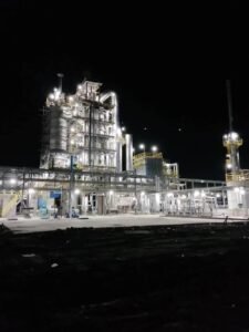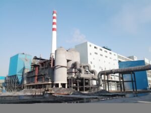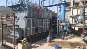
Flue gas that leaves a cement kiln or electric arc furnace at 900°C and vents straight to atmosphere is not just wasted energy — it is a recurring invoice your plant pays every operating hour. At 6,000–8,000 hours a year, those losses compound fast: fuel bills stay high, carbon liabilities accumulate under pricing schemes that now clear USD 50/tonne CO₂ in the EU ETS, and regulators tightening NOₓ/SOₓ ceilings below 50 mg/Nm³ are running out of patience with plants that haven’t modernized their exhaust handling. The answer isn’t a single technology swap. It’s a shift toward purpose-engineered waste heat recovery boilers (WHRBs) that are increasingly being designed around decarbonization targets, not just energy accounting.
Sustainability trends shaping waste heat recovery boilers in the 2020s include tighter emissions regulations, carbon pricing pressure, digital monitoring for efficiency optimization, and rising demand for high-pressure steam integration (up to 9.8 MPa) with combined heat and power systems. Modern WHRBs now recover heat from exhaust streams between 300°C and 1,100°C at thermal efficiencies of 85–92%, with payback periods of roughly 2–5 years depending on local electricity prices, fuel costs, and annual operating hours.
What’s changed in the last few years isn’t the basic thermodynamics — a heat exchanger is still a heat exchanger — but the strategic weight that plant owners, procurement teams, and EPC contractors are now putting on WHRB selection. Carbon accounting, grid export economics, and increasingly strict stack emission limits have turned what used to be a back-of-envelope energy-saving calculation into a boardroom-level infrastructure decision. The trends driving that shift are worth understanding in detail.
Low-Carbon Integration: Coupling Waste Heat Recovery Boilers with Green Energy Systems
The shift happening right now isn’t just about recovering heat — it’s about threading WHRBs into a broader low-carbon energy architecture that didn’t exist at plant design stage. Engineers who treat the WHRB as a standalone unit are already behind. The real engineering challenge today is making these systems interoperable with intermittent renewables, emerging hydrogen supply chains, and carbon accounting frameworks that increasingly determine project financing.
Hybrid WHRB-Solar Thermal: Stabilizing Steam When the Process Fluctuates
Parabolic trough or linear Fresnel collectors preheating feedwater to roughly 120–160°C before it enters the WHRB economizer section sounds niche, but it’s gaining real traction in Middle East petrochemical complexes and South Asian textile dyeing facilities — two sectors where exhaust gas temperatures can swing 80–150°C depending on production load. The solar pre-heat loop reduces auxiliary burner firing duty by somewhere in the range of 15–30%, depending on solar irradiance, feedwater flow rate, and how aggressively you’ve sized the collector field.
The operational benefit people underestimate is steam pressure stability. When process load drops and exhaust gas temperature falls, a conventionally configured WHRB either fires its auxiliary burner harder or lets steam pressure sag. A solar thermal buffer acts as a partial compensator, narrowing that pressure variance. You still need proper controls — a split-range valve arrangement between the solar loop and the economizer bypass is typical — but the outcome is measurable: tighter steam header pressure, fewer auxiliary burner start-stop cycles, and lower wear on burner management system components.
Green Hydrogen Co-Firing: Real Material Consequences
Retrofitting auxiliary burners on WHRBs to accept hydrogen blends from 20% up to 100% H₂ by volume is technically feasible. The combustion engineering, though, demands more respect than most retrofit proposals acknowledge upfront.
Hydrogen’s adiabatic flame temperature sits around 2,110°C versus roughly 1,950°C for natural gas. That 150–160°C differential isn’t trivially absorbed by refractory lining rated for natural gas service. Combustion chamber linings typically need upgrading to high-alumina or castable ceramic compositions with alumina content above 65–70%, and burner tile geometry usually requires redesign to manage flame shape — hydrogen flames are shorter, faster, and more prone to flashback at low firing rates. Burner suppliers like Hauck, Forney, or Selas have H₂-capable variants; specifying “H₂-ready” without confirming actual turndown ratio and flashback arrestor sizing is a procurement mistake that shows up during commissioning.
NOₓ is the other issue. Hydrogen combustion in air produces thermal NOₓ aggressively. Expect stack NOₓ to increase unless you’re using lean premix burner technology or staged combustion — something worth resolving at the front-end engineering stage, not after the burner arrives on site.
Power-to-Heat Buffering: Absorbing Surplus Renewables Through the Steam Header
Electrode boilers in the 1–10 MW range integrated directly into the WHRB steam header give a plant genuine flexibility. When grid electricity prices drop into negative or near-zero territory during renewable surplus periods — increasingly common in markets with high wind or solar penetration — the electrode boiler runs hard, supplementing WHRB steam output without touching fuel. When prices normalize, it idles.
Electrode boilers can achieve thermal conversion efficiencies above 99% when operating on grid electricityTrue
Electrode boilers convert electrical energy to heat with virtually no stack losses, achieving near-unity thermal efficiency at the point of conversion — unlike combustion systems where flue gas losses reduce net efficiency to 85–92%.
The control integration matters enormously here. The electrode boiler controller needs to receive both a real-time electricity price signal and the WHRB steam drum pressure signal, then arbitrate between them with a priority logic that doesn’t create hunting. A simple cascade PID usually isn’t enough; model predictive control or at minimum a properly tuned feedforward loop handles this better in practice.
Carbon Capture Readiness: Design Choices That Cost Nothing Now, Save Millions Later
Post-combustion capture retrofits typically require a flue gas duct takeoff point downstream of the economizer, low-temperature economizer space for cooling flue gas to below 120°C before the absorber column, and condensate return piping sized to handle the additional water load from solvent regeneration steam. None of these are exotic — but they require reserved space and specific nozzle placements that are almost impossible to add after a boiler is installed and insulated.
Specifying a PCC-ready WHRB at the order stage adds perhaps 3–6% to fabrication cost, depending on vessel size and pressure class. Retrofitting the same provisions post-installation on a running plant has typically cost 4–10 times that figure in my experience, factoring in scaffolding, production downtime, and civil modifications.
Oxyfuel-readiness has slightly different implications: the flue gas recirculation ductwork and O₂ injection points need to be accommodated in the windbox design, and the gas-side pressure drop budget must account for denser flue gas composition. These aren’t insurmountable, but they’re not afterthoughts either.
Lifecycle Carbon Credits: How Project IRR Actually Improves
WHRB projects that displace grid electricity or reduce on-site fossil fuel combustion can qualify under UNFCCC Article 6.4 mechanisms, Gold Standard Verified Emission Reductions, or regional carbon trading schemes. The financial uplift — roughly USD 3–8 per MWh of recovered energy, depending on baseline grid emission factor, verification body fees, and market liquidity — won’t rescue a marginal project, but it meaningfully shifts IRR on a project that’s already close to the investment threshold.
The critical documentation requirement is establishing a credible baseline. For a cement plant WHRB, the baseline is usually the grid emission factor plus the avoided auxiliary fuel consumption. Monitoring plan design needs to be agreed with the validation/verification body before commissioning, not after — a detail that EPC contractors frequently leave too late, which then delays credit issuance by one or two annual monitoring cycles.
Advanced Materials and Extended Service Life: Engineering WHRBs for Harsh Flue Gas Environments
Flue gas from a cement kiln preheater or a non-ferrous smelting furnace is not the clean, predictable stream that textbook heat exchanger design assumes. It carries sulfur compounds, alkali vapors, abrasive particulates, and moisture — sometimes all at once. Getting materials selection wrong here doesn’t just shorten tube life; it causes unplanned outages that cost more in lost production than the capital cost of the boiler itself. This is where WHRB engineering separates from general heat exchanger practice.
Dew-Point Corrosion in Low-Temperature Economizers
The sulfuric acid dew point is a function of SO₃ partial pressure and flue gas moisture content, and it typically falls somewhere between 120°C and 160°C depending on fuel sulfur content and excess air ratio — not a fixed number, despite what simplified tables suggest. When a low-temperature economizer pushes exit gas temperatures down toward 90–110°C to squeeze out the last few percentage points of recovery, the tube wall temperature on the gas side can drop below that dew point, and the consequences are rapid. Acid condensate at even 0.5–1.0% H₂SO₄ concentration will pit carbon steel in a matter of months.
The practical response is material-specific: ND steel (roughly equivalent to Cor-Ten or ASTM A242, with copper and antimony additions that form a protective patina under intermittent condensation) works well for flue gas with moderate sulfur loading and metal wall temperatures staying above roughly 80°C. For more aggressive conditions — high-sulfur residual oil combustion, Claus tail-gas streams — borosilicate glass-coated tubes or PTFE-lined transfer surfaces are worth the 20–40% cost premium over bare ND steel, because a single acid attack that forces a tube bundle replacement will exceed that premium several times over. Always confirm the actual SO₃ content by stack sampling, not estimation; I’ve seen plants specify carbon steel economizers based on “calculated” SO₃ levels that turned out to be two to three times lower than measured reality.
High-Temperature Oxidation Resistance Above 900°C
Superheater tubes in glass tank regenerator WHRBs and copper smelter off-gas boilers operate in flue gas at 900°C–1,100°C — a regime where conventional SA-210 carbon steel is simply not a candidate. SA-213 T91 (9Cr-1Mo-V) and T92 (9Cr-2W) ferritic alloys offer creep rupture strengths roughly 2–3× higher than T22 at 600°C metal temperature, and they’re the standard workhorse for these applications. For truly corrosive high-temperature streams carrying SO₂, chlorine, or heavy metal vapors — common in secondary copper or lead smelting — Inconel 625 weld overlay cladding on tube OD adds a further barrier. The cost delta versus bare T91 is significant, perhaps 4–7× on a per-meter basis, but Inconel cladding on a 40-tube superheater panel is still a fraction of the downtime cost from a sulfidation failure at full production.
SA-213 T91 tubes provide substantially higher creep rupture strength than T22 at elevated temperatures, making them more suitable for high-temperature WHRB superheater applicationsTrue
T91 (9Cr-1Mo-V) has a minimum creep rupture strength at 600°C approximately 2–3× that of T22 (2.25Cr-1Mo), as documented in ASME BPVC Section II Part D allowable stress tables. This is well-established metallurgical data.
Erosion Management in Dust-Laden Cement and Steel Streams
Fly ash loading above 30 g/Nm³ at cement kiln preheater exits demands a different tube bank geometry than what you’d specify for a clean gas application. Staggered tube banks with transverse pitch-to-diameter ratios S₁/d ≥ 3.0 reduce impingement velocity and allow ash to pass through rather than bridge across tubes; tighter pitches look attractive for heat transfer area on paper but lead to localized erosion that strips 1–2 mm of tube wall per year in the worst positions. Ceramic tile baffles at flow-entry zones and replaceable leading-edge tube shields — cast basalt or SiC-faced — have shown 40–60% reductions in tube thinning rate in field installations versus unprotected designs. Replaceable shields matter operationally: you want maintenance crews swapping a shield during a scheduled outage, not cutting out and re-welding tube sections.
Online Cleaning: Matching the Technology to the Fouling Mechanism
Soot blowing strategy depends almost entirely on the deposit type. Rotary steam soot blowers handle light to moderate fly ash deposits effectively and are the default choice in most cement and steel WHRB applications. Sonic horn systems work well in MSW boilers where sticky chloride-bearing deposits form on tube surfaces at 200–350°C — the acoustic pressure disrupts the deposit before it sinters. High-pressure water lance cleaning is increasingly used during planned outages in black liquor and biomass syngas WHRBs, where tightly bonded carryover deposits resist steam blowing entirely. In practice, many plants run a combination: steam soot blowers on the high-temperature passes during operation, water lancing offline quarterly or semi-annually. Skipping scheduled cleaning in a biomass syngas WHRB is a reliable way to lose 8–12% of heat transfer performance within a single campaign.
Pressure Part Certification and Material Traceability
Material certification is not paperwork formality — it is what allows a boiler built in one country to be legally commissioned in another. Pressure parts for export WHRBs need full material traceability, third-party inspection, and standard-specific documentation. Taishan Group’s manufacturing facilities hold CCC certification for domestic China supply, ASME ‘S’ and ‘U’ stamps for North American and many Asian markets, and PED 2014/68/EU conformity for European projects, alongside compliance with EN 12952 (water-tube) and GB/T 16507. This matters practically: an EPC contractor specifying a WHRB for a plant in the GCC or Southeast Asia needs stamp documentation in the bid package, not as an afterthought six months into fabrication. Sourcing a boiler without confirming applicable stamps upfront is one of the more expensive procurement mistakes you can make on a greenfield project.
Multi-Pressure and Supplementary-Fired WHRB Configurations: Matching Steam Parameters to Process Needs
Choosing the wrong pressure configuration is one of the more expensive mistakes you can make on a WHRB project — not catastrophic on day one, but it shows up in every quarterly steam balance report and eventually in a retrofit cost that nobody budgeted for. The exhaust profile of the host process drives almost everything: temperature, mass flow, oxygen content, and whether that flow is steady or swings hard with production shifts.
Single-Pressure Natural Circulation Units
For smaller industrial applications — food processing, textile dyeing, pharmaceutical API plants, and compact chemical skids — a single-pressure natural circulation WHRB is usually the right call. Exhaust flows below roughly 80,000 Nm³/h and steam requirements in the 1.0–4.0 MPa / 180–350°C band are well within what a straightforward drum-type unit handles without forced circulation pumps adding complexity and maintenance overhead. Natural circulation is forgiving; the buoyancy-driven flow self-regulates across moderate load swings, which suits facilities that run at variable throughput. Startup from cold is slower than a forced-circulation design — typically 45–90 minutes to stable steam conditions depending on drum wall thickness — but most process plants in these sectors are not cycling daily anyway. Keep pinch point margins reasonable (12–18°C is typical here) and don’t over-optimize: a slightly conservative heat surface area is cheaper than a tube bundle that fouls in eight months because approach temperature was too tight for a dirty flue gas stream.
Dual-Pressure Forced Circulation for CCGT and Gas Engine Recovery
Combined cycle gas turbine installations and large reciprocating gas engines almost always justify a dual-pressure configuration. The exhaust temperature profile from a gas turbine — typically 450–580°C at full load — contains enough enthalpy to simultaneously serve a high-pressure steam circuit (4.0–9.8 MPa) for power generation and a low-pressure circuit (0.3–1.2 MPa) for site heating, deaeration, or process use. Forced circulation pumps are standard here; the higher pressures and more complex flow paths make natural circulation unreliable across the operating range. The LP section recovering heat that would otherwise exit the stack is where the economics often close the payback gap — recovering an extra 8–15% of total exhaust enthalpy from what looks like “leftover” low-grade heat makes a meaningful difference when plant operating hours run 7,000–8,000 h/year.
Triple-Pressure Reheat HRSGs for Large Gas Turbine CHP
Large-frame gas turbines in combined heat and power plants push the design toward triple-pressure reheat HRSGs. HP drums operating at 9.0–12.5 MPa, intermediate pressure at 2.5–4.0 MPa, and LP at 0.4–0.7 MPa is the established architecture. Pinch point optimization is where engineering hours pay off: target pinch temperatures of 8–15°C and approach temperatures of 5–10°C to maximize exergy recovery, but tighten those numbers too aggressively and you risk steaming in the economizer during load transients. In practice, a pinch of 10–12°C is where most experienced HRSG engineers settle unless the fuel price environment is extreme enough to justify the additional surface area cost.
Optimizing pinch and approach temperatures in triple-pressure HRSGs to the 8–15°C and 5–10°C ranges respectively can increase overall plant electrical efficiency by 2–4 percentage points compared to conservative designs.True
This is consistent with published thermodynamic analyses of large combined cycle plants and HRSG manufacturer performance data; the exact gain depends on gas turbine exhaust temperature, steam turbine backpressure, and condenser cooling conditions.
Supplementary Firing: Managing the Oxygen Window and NOₓ
Duct burners installed at the WHRB inlet duct can boost steam output by 30–80% during peak demand periods — a useful tool for plants where the gas turbine or process furnace cannot be oversized just to cover demand spikes. The hard constraint is oxygen. Gas turbine exhaust typically carries 13–16% O₂, which supports supplementary combustion without a dedicated air supply. Natural gas is the most common duct burner fuel; LPG and light fuel oil work but complicate turndown behavior and emission compliance. Minimum O₂ at the duct burner inlet should stay above 16% to maintain stable flame and avoid CO excursions. Lean premix duct burner designs — now widely available from vendors like Coen, Forney, or Hauck — routinely achieve below 40 ppm NOₓ at 15% O₂ reference, which keeps you inside the 50 mg/Nm³ ceiling most export markets now enforce. Turndown ratio matters more than some projects acknowledge: if the supplementary firing system can only turn down to 40% of rated heat input, you will have overshooting steam pressure during shoulder demand periods unless the control logic is carefully tuned.
Water-Tube vs. Fire-Tube: The Threshold That Actually Matters
Fire-tube (shell-and-tube) WHRBs are practical and cost-effective when exhaust flow stays below roughly 30,000 Nm³/h and operating pressure is under 2.5 MPa. They are compact, shop-fabricated, and arrive on site ready to commission — a real advantage on remote or space-constrained sites where civil works are expensive. Above those thresholds, water-tube design is not optional; it is a structural and safety necessity. Water-tube units tolerate higher pressures, handle larger exhaust volumes, and allow modular heat surface arrangement across superheater, evaporator, and economizer sections. The trade-offs are real: water-tube units are heavier, require more field erection time (typically 3–6 weeks longer on a comparable project), and need better maintenance access planning because tube bundle inspection and cleaning is more involved. For overseas sites with limited crane capacity or tight plot plans, that field erection timeline has cost implications that sometimes get underestimated during early project scheduling.
Digitalization and Predictive Maintenance: Smart WHRB Monitoring Trends Reducing Unplanned Downtime
Unplanned shutdowns on a waste heat recovery boiler don’t just cost you the downtime — they ripple back through the entire host process. A cement kiln that has to throttle output because the WHRB tripped offline can lose 8–15 hours of production before stable conditions return. That’s the reality most maintenance managers learn the hard way, once.
DCS Integration: The Foundation Layer Nobody Should Shortcut
A properly integrated WHRB runs on a distributed control system with a fairly well-defined set of I/O points. Drum level uses three-element control — feedwater flow, steam flow, and drum level signal working together — because single-element control on a WHRB serving a variable exhaust stream will hunt badly during load swings. Flue gas temperature profiling typically requires 6–12 thermocouple zones along the gas path, from economizer inlet down to stack, and these aren’t optional: they’re how you catch a fouling event before it becomes a tube failure.
Communication protocols matter more than they used to. Older installations running Modbus RTU still work fine for local control loops, but if you’re connecting the WHRB into a plant-wide MES or SCADA, OPC-UA is the practical standard now — it handles the security handshake and data modeling that Modbus simply wasn’t designed for. PROFIBUS DP still shows up frequently on European-built auxiliaries, so a mixed-protocol environment is common. Budget for the gateway hardware; don’t assume the DCS vendor handles it automatically.
IIoT Sensors: Where the Real Predictive Value Lives
Wireless vibration sensors on circulation pump bearings and soot blower drives have become genuinely cost-effective over the last few years — installation cost is a fraction of wired alternatives, and the ISO 10816-3 velocity thresholds give you a defensible alarm setpoint rather than guesswork. In my experience, soot blower drives are the component most frequently ignored until they fail, partly because they’re intermittent-duty and partly because they’re physically awkward to reach for manual checks.
Ultrasonic wall-thickness monitoring on erosion-prone tube rows — typically the leading rows in the superheater and the first pass of the convection bank — is still underdeployed in most plants I’ve seen. Spot checks during annual outages find damage after the fact. Continuous or semi-continuous ultrasonic monitoring catches thinning trends early enough to plan a targeted tube replacement during a scheduled window rather than an emergency repair.
Flue gas oxygen trim analyzers deserve special mention for supplementary-fired units. Holding excess O₂ within a tight band — rather than running conservatively high to avoid CO breakthrough — saves roughly 1.5–3.0% fuel consumption. The actual figure depends on burner type, fuel composition, and how aggressively the original commissioning team set the trim control. Over 7,000 operating hours per year, that’s a meaningful fuel cost reduction.
Tube Fouling Prediction: Getting Ahead of the Efficiency Curve
AI-based fouling prediction models work by tracking the differential between economizer inlet and outlet temperatures against the gas-side pressure drop trend simultaneously. Either signal alone is noisy; together, they give a reasonably reliable picture of deposit buildup rate. Well-trained models on sufficient historical data can flag a cleaning requirement 200–400 hours in advance — which is enough time to schedule a soot blowing campaign or a short outage rather than react to a sudden efficiency drop.
That efficiency degradation, left unchecked, typically runs 3–5% before anyone notices it in the steam output numbers. On a WHRB generating electricity for internal consumption, that’s a directly measurable cost.
AI-driven fouling prediction models can flag cleaning requirements 200–400 hours before efficiency degradation becomes critical on WHRB economizer sections.True
Fouling prediction using combined economizer temperature differential and gas-side pressure drop trends is an established technique in industrial heat recovery boiler monitoring, supported by field deployments in cement and steel applications.
Digital Twin Modeling: Benchmarking Reality Against Design
A digital twin of a WHRB’s thermal-hydraulic performance isn’t the futuristic concept it’s sometimes marketed as — it’s essentially a steady-state and transient simulation calibrated to design heat transfer coefficients, running continuously against live process data. When actual U-values drift below design benchmarks by more than a defined threshold, the model flags it. Engineering teams can then investigate whether the cause is fouling, flow distribution changes, or a mechanical issue — before scheduling a targeted intervention during the next planned outage rather than scrambling during a failure.
The practical limit is data quality. Garbage instrumentation produces garbage twin outputs. Calibration of thermocouples and flow meters on a 12–18 month cycle is the minimum; plants that skip this find their digital twin telling them nothing useful within two years.
Remote Monitoring as a Service: Practical for Overseas Projects
For overseas WHRB installations, resident engineering support is expensive and sometimes simply unavailable in remote locations. Cloud-based performance dashboards connected via secure OPC-UA tunnels can give a remote engineering team — ours included — visibility into drum level trends, heat rate deviations, and alarm histories in real time. Taishan Group’s RMaaS offering covers alarm management, performance benchmarking against baseline, and direct remote engineering consultation, which typically reduces annual O&M costs by roughly 12–18% compared to equivalent resident-engineer coverage. The range depends heavily on local labor rates, site remoteness, and how many boilers are covered under a single monitoring contract.
This isn’t a replacement for local operators. It’s a force multiplier for them.
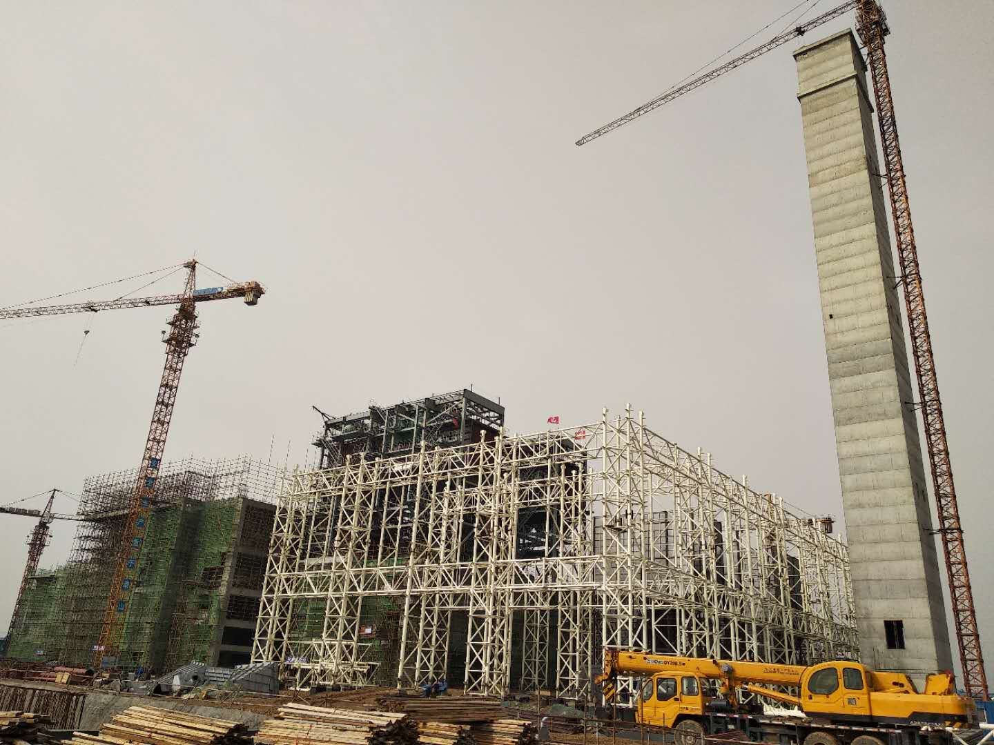
Emission Control Integration: Meeting Global NOₓ, Particulate, and CO₂ Standards Through WHRB System Design
Designing a waste heat recovery boiler without a fully integrated emission control strategy is, frankly, a project waiting for a compliance crisis. Permit conditions in the EU, Southeast Asia, and the Middle East have tightened considerably over the last five years, and what cleared environmental review in 2018 often won’t pass today. For any export project — EPC or equipment supply — the emission control train needs to be scoped and budgeted from the front-end engineering phase, not bolted on as an afterthought.
NOₓ Control in Supplementary-Fired Configurations
When a supplementary duct burner is added to boost steam output during process demand peaks, NOₓ emissions jump unless the burner is selected carefully. Ultra-low NOₓ duct burners can hold emissions below 25 mg/Nm³ at 6% O₂ reference — but that figure assumes the burner is sized for the actual flue gas oxygen content and velocity profile of the host exhaust, not just rated thermal input. Get those conditions wrong and you’re running 40–60 mg/Nm³ in practice, which will breach EU IED limits before the plant completes commissioning.
Where burner design alone isn’t enough, SCR is the standard answer. Catalyst placement matters enormously: the optimum temperature window is roughly 280–420°C, which on a typical WHRB puts the SCR module between the superheater outlet and the economizer inlet. Squeeze it in too close to the superheater and catalyst sintering becomes a concern; drop it downstream of the economizer and you’re often below 250°C, where ammonia slip increases and catalyst activity falls sharply. Aqueous ammonia injection systems need to be sized with a realistic NSR (normalized stoichiometric ratio) of 0.9–1.05 depending on inlet NOₓ load — undersizing the storage and vaporizer skid is a recurring procurement mistake, especially on projects where ammonia delivery logistics are difficult.
Protecting Heat Transfer Surfaces From Particulate Damage
Cement kilns, electric arc furnaces, and certain chemical process off-gases carry dust loadings that will blind and erode bare WHRB tube banks within months if they enter untreated. Industry practice is to reduce inlet dust loading below roughly 5 g/Nm³ before the gas enters the boiler proper — high-efficiency cyclones or electrostatic precipitators (ESP) are both viable upstream options depending on particle size distribution and gas temperature. Cyclones are simpler and handle high-temperature streams well, but collection efficiency drops for particles below about 10 µm; ESP is more effective across the size range but adds capital cost and a high-voltage maintenance burden.
One item procurement teams routinely underestimate: pressure drop. A well-designed cyclone pre-separator typically adds 0.8–1.5 kPa across the system. That sounds small, but on a large cement line where the ID fan is already running near its duty point, an additional 1 kPa of resistance can mean either a fan motor upgrade or a measurable reduction in kiln throughput. Pressure drop budget allocation needs to be negotiated with the process engineer before equipment is specified, not discovered during commissioning.
SO₂ and HCl Management in Waste-to-Energy and Biomass Applications
Dry sorbent injection of Ca(OH)₂ upstream of the WHRB economizer effectively reduces HCl and SO₂ concentrations in waste-to-energy and biomass flue gas streams.True
DSI with hydrated lime is a well-established acid gas control method in WtE and biomass combustion. The Ca(OH)₂ reacts with HCl and SO₂ at temperatures typically above 140°C, and placement upstream of the economizer ensures sufficient reaction time and temperature. This approach is used in plants operating under EU IED and similar standards globally.
Waste-to-energy and biomass WHRBs deal with acid gas chemistry that standard boiler steel simply wasn’t designed for. Dry sorbent injection (DSI) using Ca(OH)₂ upstream of the economizer is the most common first-stage control — reagent consumption runs roughly 1.5–2.2 kg per kg of HCl removed, varying with inlet concentration, residence time, and stoichiometric ratio. The catch is ash. DSI significantly increases the volume and reactivity of collected fly ash, which changes the ash handling system design, discharge conveyor sizing, and disposal classification in most jurisdictions. Tube material selection in the downstream economizer also shifts: 09CrCuP or equivalent weathering-grade steel is worth the premium over plain carbon steel in these environments, particularly in the cold end where acid condensation risk is highest.
Semi-dry scrubbers (spray dryer absorbers) integrated downstream of the boiler provide a second-stage removal option where a single DSI pass isn’t sufficient to meet permit limits below 10 mg/Nm³ for HCl. This adds a recycle ash stream back into the system, and the interface between the scrubber vendor and the WHRB supplier needs to be contractually clear on who owns the ducting and ash discharge equipment between the two units.
Managing Acid Dew Point in Low-Temperature Economizer Design
Standard WHRB economizer designs maintain exit flue gas temperature 15–20°C above the calculated acid dew point — typically somewhere between 130–160°C depending on sulfur content and moisture in the flue gas. That margin protects carbon steel tube banks from external corrosion but leaves a significant chunk of sensible and latent heat in the stack.
On natural gas-fired applications, where SOₓ content is negligible, deliberate sub-dew-point condensing economizers are a different proposition. Recovering latent heat from water vapor condensation can lift overall system thermal efficiency by an additional 5–8 percentage points, which at high operating hours (7,000 h/year, say) represents meaningful fuel or equivalent electricity savings. These units require borosilicate glass tube or PTFE-coated surface construction, plus a condensate neutralization and drainage system. They’re not universally applicable — don’t try this on a biomass or mixed-fuel system with variable sulfur.
Continuous Emission Monitoring: Design Requirements That Get Overlooked
CEMS requirements under EU IED Annex V, US EPA 40 CFR Part 60/63, and equivalent regulations in the Middle East and Southeast Asia typically mandate continuous monitoring of O₂, CO, NOₓ, SO₂, and particulates. What frequently gets missed in early WHRB duct design is the straight-run requirement for sampling ports: EPA Method 1 calls for 8 duct diameters of unobstructed straight run upstream and 2 diameters downstream of the measurement plane. On a congested plant layout with ductwork turning and splitting within short distances, retrofitting compliant sample ports is expensive and sometimes structurally awkward. Build the measurement locations into the duct arrangement from the start.
The CEMS analyser house location matters for maintenance accessibility — analyzers tucked above economizer casing at elevation 12–15 m, reachable only by a temporary scaffold, will see poor calibration discipline and data availability penalties from the regulator. In my experience, plants that treat CEMS as a regulatory checkbox rather than an operational instrument tend to have more permit violations, not fewer.
Circular Economy and Waste-to-Energy WHRB Applications: Recovering Heat from MSW, Biomass, and Industrial Waste Streams
The waste heat recovery boiler market has, for a long time, been dominated by cement kilns, steel reheating furnaces, and glass tank exhausts. That’s changing. EPC clients across Southeast Asia, the Middle East, and sub-Saharan Africa are increasingly specifying WHRBs for municipal solid waste incineration, biomass gasification, and hazardous waste treatment — applications where the fuel is waste itself, and the regulatory exposure is considerably higher.
MSW Incineration WHRBs: Design Specifics That Cannot Be Shortcuts
Grate-fired mass-burn incinerators and circulating fluidized bed (CFB) combustors processing municipal solid waste deliver exhaust into the boiler radiation chamber at roughly 850–1,050°C, depending on waste calorific value and excess air ratio. The critical constraint here isn’t thermal — it’s regulatory. EU Directive 2010/75/EU mandates a minimum 2-second flue gas residence time above 850°C before any heat extraction begins, specifically to ensure dioxin and furan destruction. Get this wrong and you’re not looking at an efficiency penalty; you’re looking at permit revocation.
For power generation from MSW, steam parameters typically land in the 4.0–6.5 MPa / 400–450°C range. Going higher runs into chloride-induced superheater corrosion from HCl concentrations that can reach 1,000–2,000 mg/Nm³ in raw flue gas — a real constraint that forces most MSW boiler designers toward Inconel or high-alloy cladding on the final superheater pass, or simply capping live steam temperature at around 400°C and accepting the turbine efficiency trade-off. Net electricity output for modern grate-fired units is typically 550–750 kWh per tonne of processed waste, depending on waste moisture content, local cooling water temperature, and turbine back-pressure.
EU Directive 2010/75/EU requires a minimum 2-second flue gas residence time above 850°C in MSW combustion systems to thermally destroy dioxins and furans before heat recovery begins.True
This is a codified requirement under the Industrial Emissions Directive (2010/75/EU), Article 50 and Annex VI, governing waste incineration plants across EU member states and widely adopted as a design reference standard in export markets.
Biomass Gasification Syngas WHRBs: The Tar Problem
Biomass and agricultural residue gasifiers — rice husk, sugarcane bagasse, wood chips — produce syngas with a lower heating value of roughly 4–8 MJ/Nm³, depending on feedstock moisture and gasifier type. That low calorific density means higher volumetric flow for equivalent thermal output, which affects tube bundle sizing and fan duty.
The practical hazard is tar. Below roughly 400°C in the convection pass, tars begin condensing on tube surfaces, building a fouling layer that’s sticky, insulating, and — if it catches — a fire risk during inspection outages. Experienced designers address this with high-velocity gas passes (keeping flue gas above 8–10 m/s through the economizer section to discourage deposition) and, on some installations, online water-washing economizer sections that periodically flush tube banks during reduced-load windows. It’s not elegant, but it works. Soot blowers alone are usually insufficient for heavy tar fouling.
Hazardous Waste Incineration: Vertical Radiation Pass Design
Co-processing liquid organic waste, clinical waste, and persistent organic pollutants (POPs) introduces chlorinated and brominated compounds that accelerate corrosion well beyond what a conventional WHRB membrane wall handles. The standard design response is a vertical radiation pass with an empty radiation chamber — no tubes, just refractory-lined membrane walls — providing the required >2-second residence time for complete burnout and dioxin destruction before convective surfaces appear. Access for inspection is non-negotiable; Basel Convention treatment standards and most national hazardous waste regulations require documented combustion performance verification, which means rodding and borescope ports spaced appropriately along the radiation chamber length.
Refractory selection matters here more than in almost any other WHRB application. Silicon carbide-based castables perform better than standard high-alumina in halogenated flue gas environments, though the cost premium — roughly 30–50% over standard refractory on the radiation chamber — is usually justified by the extended interval between relining campaigns.
Black Liquor Recovery Boilers: A Specialized WHRB Variant
Kraft pulp mill recovery boilers occupy their own design category. They recover heat from black liquor combustion while simultaneously performing inorganic chemical recovery — the smelt from the furnace floor goes back into the causticizing circuit. Steam parameters can reach 10.5 MPa / 500°C on large modern units, higher than most MSW applications, which pushes superheater alloy selection hard against alkali chloride deposition limits. Sodium and potassium chlorides in recovery boiler flue gas are aggressive; composite tube construction and careful sootblower sequencing are standard practice.
Auxiliary equipment scope on recovery boilers is substantial: economizers, air heaters (both primary and secondary), electrostatic precipitators for smelt carryover particulate, and condensate systems. Taishan Group supplies these associated auxiliary packages to complement recovery boiler installations, which matters to EPC contractors who need a single-source supplier for the heat recovery island rather than coordinating three separate vendors.
Closing the Loop: Circular Economy Metrics as Bankable ESG Indicators
Landfill diversion and recovered material streams are becoming hard financial inputs, not just sustainability optics. Bottom ash from MSW grate-fired units, properly tested, qualifies as road aggregate substitute in many jurisdictions, reducing disposal costs by USD 15–40 per tonne depending on local tipping fees. Fly ash captured by the ESP or bag filter can substitute cement clinker at 10–15% replacement rates, subject to heavy metal leaching tests — this is market-dependent and requires third-party certification, but it’s achievable and increasingly written into project ESG reporting frameworks demanded by development finance institutions funding new waste-to-energy projects across Asia and Africa.
Net energy output per tonne processed, carbon avoided per year, and percentage waste diverted from landfill are now routinely tracked as bankable ESG reporting indicators for project finance. For plant owners and EPC contractors preparing bankable feasibility studies, these figures need to be grounded in actual WHRB thermal performance data — not marketing estimates — and that starts with getting the boiler design specification right from the first engineering gate.
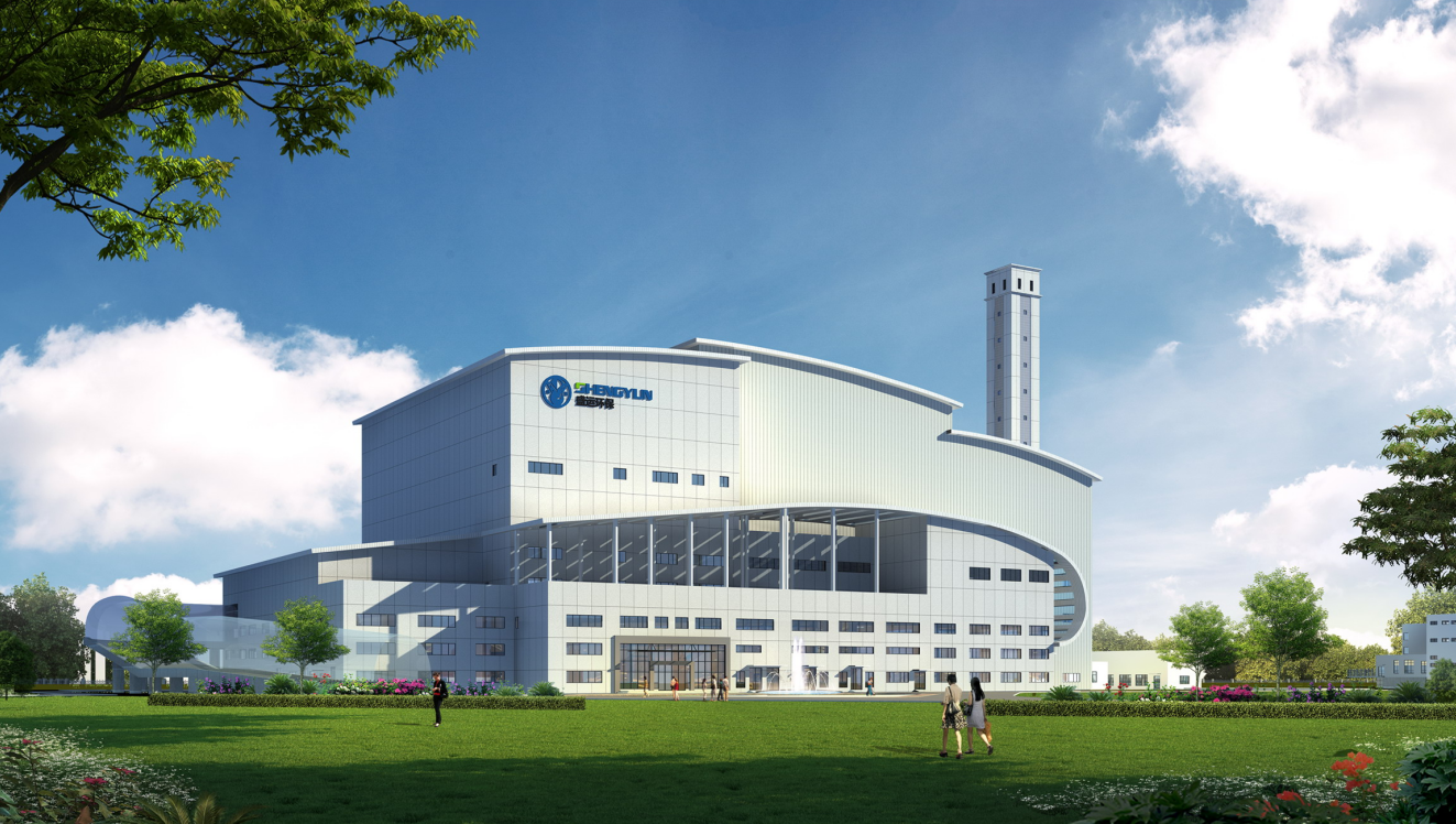
EPC Project Execution and Overseas Site Commissioning: Delivering WHRB Projects to International Standards
Getting a waste heat recovery boiler from a manufacturer’s drawing office to a running plant in another country is where a lot of projects quietly go wrong. The technology is understood. The contractual pain — missed commissioning windows, undersized equipment, permit delays, a contractor who disappears after handover — that’s where overseas buyers absorb real losses. EPC execution quality is what separates a 2.5-year payback from a 6-year one.
Front-End Engineering and the Cost of Bad Data
Every WHRB project begins with the host process exhaust characterization, and in practice this step is routinely underestimated. The minimum data set an engineer actually needs includes exhaust gas volumetric flow in Nm³/h at actual operating temperature, inlet temperature range (not just design-point maximum — transient swings matter for thermal fatigue), full flue gas composition including O₂, CO₂, H₂O, SO₂, HCl, and dust loading in g/Nm³, available draft margin in Pa, and site utility conditions: cooling water temperature, steam header pressure at tie-in, and elevation above sea level, which affects fan sizing and steam saturation curves.
When that data arrives incomplete — and it often does, especially on brownfield retrofits where the original process was never properly instrumented — the conservative engineering response is to overdesign. In practice that means adding 15–20% margin on heat transfer surface, upsizing the induced draft fan, and specifying a heavier structural steel support frame. The capital cost consequence is typically 10–20% higher than a correctly scoped design would require. That’s real money on a unit that might already carry a USD 1.5–4 million installed cost. A competent FEED phase, including a site visit to log operating data over at least one representative production shift, pays for itself easily.
Modular Fabrication: What It Actually Changes on Site
Pressure parts — steam drums, mud drums, headers, and tube bundles — are manufactured in Taishan Group’s certified workshops to ASME Section I or EN 12952, depending on the destination market’s regulatory preference. Shop fabrication under controlled conditions with qualified welders and traceable material heat numbers produces better weld quality than field erection, full stop. Pre-assembly into skid-mounted modules reaching up to roughly 80 tonnes per lift compresses site civil work and reduces commissioning duration by around 30–40% compared to stick-built erection, which is especially significant when the plant owner is paying demurrage on a kiln or furnace that can’t restart until the boiler is online.
Shipping logistics require early coordination. Flatbed transport and heavy-lift vessels have booking windows measured in weeks during peak seasons, and port crane capacity at the destination site is often the constraint nobody checks until the modules are sitting on the dock.
Third-Party Inspection: Hold Points That Matter
For export projects, third-party inspection through Lloyd’s Register, Bureau Veritas, TÜV Rheinland, or a client-nominated body isn’t bureaucratic overhead — it’s what makes the documentation package bankable and the equipment importable. Key hold points are raw material certification review against EN 10028 or ASTM standards, radiographic and ultrasonic testing of pressure-part welds per ASME Section IX, hydrostatic testing at 1.5× design pressure with a witnessed pressure hold, and final dimensional verification against certified drawings. The deliverable documentation package — material test reports, weld maps, NDE records, and the pressure test certificate — travels with the equipment and is frequently required by the destination country’s boiler inspection authority before the unit is permitted to operate.
Hydrostatic testing at 1.5× design pressure per ASME Section I is a standard mandatory requirement for shop-fabricated pressure vessels before shipment on export WHRB projects.True
ASME Section I PG-99 requires a hydrostatic pressure test at 1.5 times the maximum allowable working pressure (MAWP) for completed boilers. This is standard practice and a contractual hold point on internationally supplied pressure equipment.
Commissioning Workflow and Performance Acceptance Testing
Pre-commissioning follows a defined sequence. Refractory dry-out curves must be respected — rushing this step causes spalling that leads to hot spots and unplanned outages within the first 6–12 months. Chemical cleaning of pressure parts per ASME SD-108 removes mill scale and construction debris before steam raising, which protects tube internals and feedwater train components from contamination. Nitrogen blanketing during transport and storage periods longer than a few weeks prevents internal corrosion, particularly relevant for projects with extended site construction schedules in humid coastal climates.
Cold functional testing verifies instrumentation loop integrity, valve stroking, and interlock logic before any heat is applied. Hot functional testing confirms circulation, steam separation performance, and blowdown system operation under live conditions. Performance acceptance testing (PAT) measures actual thermal output against the guaranteed design curves, with a contractual tolerance of ±3%. In practice, the PAT protocol needs to be agreed in writing before contract signature — disputes over what constitutes “design conditions” at the time of testing are among the most common sources of project disputes on WHRB handovers. Operator training, a minimum of 40 hours covering classroom thermodynamics, P&ID walkthroughs, and simulator or OJT sessions on actual control interfaces, is non-negotiable for safe long-term operation, particularly at sites where the maintenance team has no prior WHRB experience.
Long-Term Service and Spare Parts Logistics
The first 18 months of operation are when most infant-mortality failures surface — mechanical seal failures on circulation pumps, soot blower element wear, safety valve seat leakage. An initial spare parts inventory sized for roughly an 18-month operating window, covering drum internals, circulation pump seal kits, soot blower elements, and safety valve trim sets, prevents a 3-week repair becoming a 14-week wait for an overseas shipment. Taishan Group maintains regional spare parts warehouses and deploys field service engineers across Southeast Asia, the Middle East, and Africa, which matters when a plant in Vietnam or Nigeria needs a technical response measured in days rather than the weeks a purely factory-based support model would require. A structured long-term service agreement (LTSA) that includes scheduled inspection intervals, performance benchmarking, and priority parts supply converts the post-commissioning relationship from reactive to genuinely supportive — which is, ultimately, where the total cost of ownership case for a well-executed WHRB project is either confirmed or quietly eroded.
Frequently Asked Questions About Waste Heat Recovery Boiler Sustainability and Selection
What minimum exhaust gas temperature and flow rate make a WHRB project economically viable?
The short answer: for a water-tube WHRB, you generally need inlet temperatures above 250°C and volumetric flows above roughly 15,000 Nm³/h before the numbers start working. Fire-tube units are more forgiving — they can make sense from around 200°C and 5,000 Nm³/h, which is why you see them behind smaller kilns and food-processing ovens where a water-tube unit would be overkill.
That said, temperature and flow alone don’t close the case. A plant running 6,500 hours per year in a region with electricity at USD 0.14/kWh has a completely different payback picture than a facility doing 4,000 hours in a market where grid power costs USD 0.07/kWh. Fuel cost displacement, local steam pricing, and whether you’re generating power or satisfying an in-plant heat load all shift the feasibility threshold. Any serious evaluation needs a proper heat balance and pinch analysis — rule-of-thumb numbers get you to the shortlist, not the investment decision.
How does a WHRB differ from an HRSG used in a combined-cycle power plant?
An HRSG is technically a subtype of waste heat recovery boiler, but it’s optimized for a very specific and relatively clean duty: gas turbine exhaust at 450–650°C with negligible particulate loading. The engineering emphasis is on multi-pressure drum arrangements, close approach temperatures, and maximum thermodynamic efficiency because the exhaust stream is predictable and the economics are tight.
General industrial WHRBs handle a far messier world — rotary kiln exit gases loaded with cement dust, glass furnace fumes carrying alkali vapors, incinerator flue gas with chlorine compounds and heavy metals. The design priorities shift toward erosion-resistant tube geometries, wider flue gas pass clearances to prevent bridging, and materials selected for corrosion resistance rather than pure heat transfer performance. Confusing the two categories at the specification stage is a real procurement mistake; an HRSG vendor quoting against an industrial WHRB tender will often be comparing unlike equipment.
Can a WHRB generate electricity as well as process steam?
Yes, and this is increasingly the configuration clients ask for. A steam Rankine cycle arrangement — WHRB generating high-pressure steam, feeding a backpressure or condensing turbine-generator set, with the turbine exhaust supplying low-pressure process heat — is well-established across cement, steel, and chemical plants. Realistic electrical conversion efficiency runs 15–28% of recovered thermal energy, depending heavily on steam pressure and temperature (higher superheat at 4–9.8 MPa gives you the upper end), turbine size and configuration, and whether you’re running backpressure or condensing mode.
The practical caveat: a small turbine set below roughly 1 MW often struggles to justify its capital and maintenance cost unless electricity prices are high or there’s a regulatory incentive. At 3–5 MW and above, the economics are usually solid.
What are the main maintenance requirements and expected service life?
Pressure parts on a properly operated water-tube WHRB are designed for 25–30 years of service — but “properly operated” is doing a lot of work in that sentence. Water treatment is non-negotiable: phosphate or AVT (all-volatile treatment) regimes per ASME consensus guidelines, maintained consistently, not just when the water chemistry analyzer throws an alarm. Tube failures from corrosion pitting or stress-corrosion cracking are almost always traceable to water treatment lapses or chemistry excursions that were tolerated for too long.
Annual outages should cover tube inspection, soot blower mechanism overhaul (these take more abuse than most people budget for), and safety valve testing and certification. Major inspections at 4–6 year intervals include internal drum examination, non-destructive evaluation of high-stress welds, and refractory assessment in the gas inlet section. Plants that skip or abbreviate major inspections to save a week of downtime routinely pay for it in forced outages.
Should I retrofit my existing fired boiler plant with a WHRB or replace it entirely?
This is a judgment call that genuinely requires a thermal audit first. The key variables: does the available exhaust heat potential actually match your steam demand, or will you be banking excess steam with nowhere to use it? Is there site footprint for a WHRB installation without disrupting the existing process? What backpressure does the added WHRB flue gas path impose on the host process fans — because if the process is fan-limited, you may need to upsize induced draft equipment at additional cost.
The interface with existing steam header pressure levels is often underestimated. A WHRB generating steam at 1.6 MPa cannot simply be paralleled with an existing system running at 2.5 MPa without a let-down station or header reconfiguration. Replacement becomes more attractive when the existing plant is aging, when steam parameters need to change anyway, or when a greenfield WHRB can be optimized as the primary steam source with the fired boiler as backup.
WHRB retrofit projects consistently deliver shorter payback periods than fired boiler replacement when the host process exhaust temperature exceeds 400°C and plant operating hours exceed 6,000 per year.True
At these parameters, recoverable energy is sufficient to generate meaningful steam or power output, and the capital cost of a retrofit WHRB is typically 40–60% of a new fired boiler of equivalent capacity, compressing the payback period to the 2–4 year range under median fuel and electricity price assumptions.
What sustainability certifications and performance guarantees does Taishan Group provide?
For pressure vessel compliance, our WHRBs are available with ASME S/U stamp certification for North American and international projects, PED 2014/68/EU for European installations, and GB/T 16507 for domestic and applicable export markets. These aren’t marketing checkboxes — they determine whether your project clears local statutory inspection and whether your insurance is valid from day one.
Performance guarantees on our WHRB contracts cover thermal output to ±3%, flue gas exit temperature to ±5°C, and system pressure drop to ±8%, all verified during commissioning with agreed test methods and instrumentation. For projects where clients need carbon accounting documentation — CDM or Verra VCS registration for carbon credit monetization — we can provide third-party verified baseline data and monitoring plans as part of the project scope. The defects liability period runs 12 months from commissioning acceptance, with defined response times for overseas sites, including remote diagnostic support and scheduled spare parts availability agreements for critical wear items.
6. References
Renewables for Industry — Executive Summary — International Energy Agency (IEA)
Opportunities for District Heating in the Changing Energy Landscape — International Energy Agency (IEA)
Fueling Industrial Decarbonization Solutions — United Nations Industrial Development Organization (UNIDO)
Recovery and Reuse of Waste Heat in Eco-Industrial Parks — United Nations Industrial Development Organization (UNIDO)
Waste Heat Valorisation — Improving Energy Efficiency in Process Industries — European Commission CORDIS
Industrial Waste Heat-to-Power Conversion — European Commission CORDIS
PUSH2HEAT — Next-Generation Industrial Waste Heat Upgrade Technologies — European Commission CORDIS
HURRICANE — Circular Use of Industrial Waste Heat and Resources — European Commission CORDIS
SUSHEAT — Smart Integration of Waste and Renewable Energy for Sustainable Heat Upgrade — European Commission CORDIS
Decarbonizing Industrial Heat — Waste Heat Recovery Technologies — Siemens Energy