Oil-fired boilers don’t fail all at once — they degrade in patterns, and the plant floor usually gives you plenty of warning before an unplanned shutdown forces your hand. A burner that hunts for flame, stack smoke that shifts from white to black, steam pressure that won’t hold despite adequate fuel flow — each symptom points somewhere specific, and chasing the wrong cause first is how a two-hour fix turns into a two-day outage. In a continuous-process plant running a fire-tube package boiler, even 12 hours of unplanned downtime can translate to production losses that dwarf the annual maintenance budget. The good news is that the overwhelming majority of field failures trace back to a short list of root causes: combustion air imbalance, fuel delivery problems, fouled heat transfer surfaces, and control system drift. Know those four areas and you can diagnose most of what goes wrong.
Troubleshooting industrial oil-fired boilers starts with identifying whether the fault lies in the combustion system (burner, air registers, fuel train), the heat transfer path (fireside fouling, waterside scale), or the control and safety loop. Systematically checking flue gas O2 — target 2–4% for oil firing — fuel supply pressure and temperature, and boiler water chemistry eliminates guesswork and restores operation faster than component swapping.
What makes oil-fired boiler troubleshooting genuinely tricky is that a single visible symptom — say, high stack temperature — can have four or five completely unrelated root causes depending on whether you’re running No. 2 distillate or No. 6 heavy fuel oil, how old the firetube passes are, and what the feedwater treatment program looks like. The sections below work through each failure mode the way an experienced field engineer would: symptom first, then the mechanism, then the fix, with the dependencies spelled out so you’re not applying a solution from a different fuel grade or a different boiler configuration.
Diagnosing Burner Ignition Failures and Flame Instability in Oil-Fired Boilers
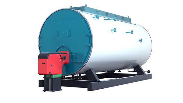
Ignition failure is the single most common emergency call on an oil-fired boiler — and also the one most likely to be misdiagnosed by inexperienced operators who replace parts instead of reading the fault sequence. Before touching anything, pull the burner controller’s fault code. The three controller families you’ll encounter most often in industrial packaged boilers are the Honeywell RM7890 series, the Siemens LFL1/LFL2 series, and comparable units like the Brahma or Riello RMG. Each uses a different LED or display code convention, but the underlying logic is identical: the controller steps through a fixed sequence (purge → pilot or direct ignition → flame prove → run), and it locks out at the first step that fails to confirm.
This distinction matters enormously. A lockout means the safety sequence reached a point where it could not verify a required condition and cut fuel as a safety act — you must manually reset after finding the cause. A soft fault or “hold” on some Siemens units means a transient condition (a pressure switch briefly dropping, say) interrupted the sequence but the controller is willing to retry. Treating a lockout as a nuisance reset and cycling power repeatedly without investigation is how a small fuel oil spillage inside a furnace becomes a serious incident.
Reading the Fault Code Against the Physical System
Map the code to the sequence step, not to a component. An RM7890 locking out at the flame-prove period (roughly 10 seconds after ignition attempt) points to scanner, electrode, or fuel supply — not to the controller itself. The same lockout code at pre-purge points immediately at airflow proving: the draft fan pressure switch or air damper end-switch hasn’t confirmed. Don’t assume the component labeled in the manual is the culprit; trace the signal path from the switch back to the controller terminal.
Fuel Supply: The Checklist Nobody Completes Fully
Pressure-jet burner nozzles require roughly 8–12 bar at the nozzle inlet to atomize properly — the exact figure depends on nozzle size and fuel viscosity. Start at the fuel pump. Pull the pressure gauge port downstream of the pump and check against the burner manufacturer’s datasheet. A worn gear pump in a high-duty-cycle boiler will lose 15–25% of its pressure rating over 18–24 months, depending on how dirty the fuel supply is.
Check the strainer before the pump, not after. A partially blocked 100-mesh strainer at the supply skid can look fine visually but restrict flow enough to starve the pump under firing conditions. Solenoid valve response is easy to test: disconnect the coil and check resistance (typically 8–25 Ω depending on voltage rating); a reading near zero means a shorted coil that fires but doesn’t seal properly; open circuit means the valve never opened. Foot-valve cavitation shows up as hunting pump pressure — unstable, pulsing gauge — usually traceable to a partially closed isolation valve or a flooded suction line with entrained air.
Atomizer Nozzle: Wear Tolerance Is Tighter Than Most People Think
A worn nozzle orifice that deviates more than ±2% from rated flow changes the flame shape enough to cause scanner dropout, especially on UV cells that are aimed at a specific flame envelope geometry. Inspect nozzles every 1,000–2,000 operating hours depending on fuel cleanliness; heavy fuel oil (HFO) with high asphaltene content can clog a nozzle in a fraction of that time.
Replace nozzles with the fuel train isolated and depressurized. This sounds obvious — but in practice, technicians often crack the nozzle union with residual pressure and contaminate the electrode assembly with atomized oil, which then causes a scanner fault on the next start. Clean the nozzle holder seat, verify the new nozzle orifice size matches the burner’s rated throughput exactly, and torque to spec (typically 15–20 N·m for standard Delavan or Steinen-style fittings).
A worn pressure-jet nozzle with only 5% orifice wear can cause repeated flame-out because the spray angle deviation falls outside the flame scanner's detection cone.True
UV and ionization flame detectors have a defined field of view; a degraded nozzle produces an off-axis or widened flame cone that the scanner cannot reliably see, triggering safety shutdown even when combustion is technically occurring.
Ignition Electrode: Gap, Insulator, and High-Voltage Lead
The standard arc gap is 3–4 mm between electrode tips, measured with a feeler gauge or the setting tool included in most burner service kits. A gap less than 3 mm increases the risk of carbon bridge buildup and eventual short-circuit to the nozzle body. Over 4 mm and the transformer’s secondary voltage — typically 8–10 kV — may not reliably jump the gap under cold, damp conditions.
Ceramic insulator cracks are easy to miss because the crack is often hairline and only causes a problem under high-voltage conditions. The test: with the transformer energized and leads connected, hold a wooden stick near the ceramic and look (in low light) for tracking arcs. A cracked insulator will show a faint blue-white discharge path. High-voltage lead continuity testing needs a proper HV insulation tester, not a standard multimeter — the lead’s silicone insulation can show infinite resistance at 12 V DC but break down at operating voltage.
Flame Scanner: Fouling Is Underestimated
UV cells in particular foul faster on heavy oil than most maintenance schedules account for. A thin film of oily residue on the sight glass reduces UV transmission enough to cause intermittent flame-loss trips during the first few minutes of firing, when the combustion chamber is cold and UV intensity is lower. Clean the sight glass with IPA, not workshop rags that leave lint. If response time testing (most controllers have a self-test function) shows the scanner responding in more than 1–2 seconds to a simulated flame loss, replace the cell rather than cleaning again.
Pre-Ignition Purge: Don’t Skip the Damper Proof
Purge cycle failures — where the controller locks out before ever attempting ignition — almost always come down to two signals: the air damper end-switch and the proving pressure switch on the combustion air fan. The end-switch on a butterfly or parallel-blade damper is a small microswitch that confirms the damper reached its fully-open purge position. These switches vibrate loose over time and need re-gapping or replacement every couple of years. The fan proving switch setpoint should be confirmed against the boiler’s minimum purge airflow requirement — typically 25–30% excess air for purge — not just “does the switch close.” A setpoint that’s drifted low will confirm purge even when the fan belt is slipping and actual airflow is inadequate.
| Fault Stage | Typical Code (RM7890) | Most Likely Physical Cause | First Check |
|---|---|---|---|
| Pre-purge lockout | Airflow fault | Damper end-switch or fan proving switch | Switch gap, fan amperage |
| Ignition trial, no flame | Flame failure | Electrode gap, nozzle blockage, solenoid valve | Fuel pressure at nozzle inlet |
| Flame established, then trips | Scanner dropout | UV cell fouling, nozzle wear changing flame geometry | Clean scanner, check nozzle orifice |
| Intermittent during run | Fuel supply hunting | Pump wear, strainer blockage, cavitation | Pump pressure gauge under load |
Work through this sequence methodically. Replacing the UV cell when the problem is a worn nozzle wastes time and leaves the real fault in place.
Troubleshooting Poor Combustion Efficiency: Black Smoke, High Stack Temperature, and Excess CO
A boiler that fires reliably but burns badly is, in some ways, more insidious than one that won’t light at all. The plant keeps running, the steam pressure holds, and the problem accumulates quietly — in fuel bills, in soot deposits, and eventually in a permit violation notice or a regulatory inspection.
Reading the Flue Gas Analyzer First
Before touching any damper or fuel valve, pull a representative flue gas sample at the economizer outlet (not the breeching — dilution air skews the reading). A Testo 340, Kane 458, or similar electrochemical unit should give you simultaneous O₂, CO, CO₂, stack temperature, and ideally NOx. The target window for a well-tuned oil-fired boiler on distillate or residual fuel is 2–4% O₂, CO below 100 ppm, CO₂ in the 12–14% range, and stack temperature within roughly 30–40°C of the design value specified on your heat balance sheet. If any single parameter sits outside that band, resist the urge to adjust immediately — read all of them together. A low O₂ reading paired with high CO and elevated stack temperature tells a completely different story than low O₂ alone.
Black Smoke: Four Different Root Causes, Four Different Fixes
Ringelmann shade 1 is a faint grey haze most operators can live with. Shade 2 and above is a regulatory and efficiency problem. The temptation is to immediately open the combustion air damper, but that only corrects one of the four common causes.
Over-rich air-fuel ratio is the obvious one: O₂ below 1.5%, CO climbing, black or dark grey plume. Open the primary air register incrementally — typically 5–10% damper adjustment at a time — and re-sample after 10 minutes of steady state.
Poor atomization produces a similar visible symptom but with a speckled, oily appearance in the stack plume rather than a uniform dark cloud. This usually traces to a worn or partially blocked nozzle tip, incorrect nozzle angle for the burner quarl geometry, or, critically, fuel oil that has arrived at the burner tip below its viscosity target. For No. 6 heavy fuel oil (HFO), the oil temperature at the nozzle should reach 95–120°C to achieve roughly 12–15 cSt — below that window, atomization degrades sharply and carbon deposits begin building on internal furnace surfaces within days.
Cold furnace walls occur during startup, or after an extended low-load period. Unburned droplets hit relatively cool refractory before they fully combust. The fix here is operational: don’t rush to full firing rate. A controlled warm-up curve matters, especially on larger water-tube designs where the refractory mass is substantial.
Contaminated or off-spec fuel is the one that surprises operators. Water contamination causes intermittent flame pulsing and visible smoke puffs. High-asphaltene blends from mixed deliveries produce persistent black smoke even with correct temperature and atomization. Pull a fuel sample and check density and water content before chasing mechanical causes.
High Stack Temperature and the Efficiency Penalty
Each 15–20°C rise in flue gas temperature above the design setpoint costs approximately 1% in boiler thermal efficiency on HHV basis.True
This is a well-established rule of thumb from combustion engineering practice, consistent with ASME and industry boiler efficiency calculation methods. The exact figure depends on fuel type, excess air level, and baseline stack temperature, but 1% per 15–20°C is a reliable working estimate for oil-fired units.
On a 10 MW boiler running 7,000 hours per year on HFO, that 1% translates to a meaningful fuel cost — the exact figure depends on your local fuel price, but the direction is always the same: fouled convective surfaces cost money every hour they stay dirty.
High stack temperature almost always means one of three things: soot or scale fouling on the convective tube bank, excessive excess air blowing heat straight out the stack, or a failed economizer section. Check O₂ first. If excess air is above 25% (O₂ above roughly 4.5%), close the air damper and re-measure stack temperature after steady state. If temperature stays high with correct O₂, you have a fouling problem — schedule a tube-side inspection and sootblowing or mechanical cleaning.
CO Spike Without Visible Smoke
This is a subtle one. The plume looks clean, O₂ is in range, but the CO reading sits at 300–600 ppm or climbs intermittently. In my experience, this pattern almost always traces to combustion aerodynamics rather than air-fuel ratio. Common causes include swirl pattern disruption from a bent or worn spinner/diffuser plate, erosion of the quarl tile at the burner throat (which alters the recirculation zone geometry), or refractory spalling that creates cold pockets where combustion quenches prematurely.
You cannot diagnose this under load. Schedule a controlled shutdown, allow the furnace to cool to a safe entry temperature (typically 40°C or below at the inspection port), and visually inspect the quarl and near-burner refractory for cracking, deformation, or missing sections. Quarl replacement is straightforward on packaged fire-tube units; on larger field-erected boilers, refractory repair can take 2–4 days depending on cure time — plan accordingly.
NOx Exceedance
If your continuous emission monitoring system (CEMS) or periodic stack test shows NOx above your permit threshold, start by verifying that the flue gas recirculation (FGR) damper is actually opening to its commanded position. FGR actuators are frequently found stuck or miscalibrated during routine audits — the control system shows 20% recirculation, the damper hasn’t moved in months. Check actuator feedback against physical damper position.
If FGR is confirmed functional and NOx remains elevated, the issue is usually flame temperature — either the flame is running hotter than designed due to over-lean conditions near the primary zone, or staged-air register settings have drifted. Reducing primary air slightly to lower peak flame temperature while maintaining overall stoichiometry within the 2–4% O₂ window is the standard lever. Do this in small steps and monitor CO simultaneously — the NOx-CO tradeoff on oil flames is real and unforgiving on older single-register burner designs.
Identifying and Correcting Steam Pressure or Hot-Water Temperature Fluctuation
Pressure or temperature swings in the output circuit often get misdiagnosed as combustion problems. They’re not. A boiler firing cleanly at 91% efficiency can still deliver wildly unstable steam pressure if the controls are poorly tuned, the feedwater system is struggling, or the heat transfer surfaces are fouled. These are separate failure modes and need separate diagnostic paths.
Pressure Hunting vs. Pressure Drift — Know the Difference Before You Touch Anything
Pressure hunting — oscillating around setpoint every 30–90 seconds — almost always points to a PID controller problem: proportional gain too high, integral time too short, or a control valve with excessive hysteresis. You’ll see the burner cycling on-off rapidly, the modulation signal chasing itself. Before retuning, check whether the pressure transmitter sensing line has a partial blockage or a water trap creating lag. That alone can turn a well-tuned loop into an unstable one.
Pressure drift is different. Setpoint keeps being met, but then slowly falls away over a shift — or gradually climbs and the relief valve starts weeping. Drift usually means the heat input no longer matches demand (load step-change not accommodated, burner capacity undersized for peak) or that heat transfer is degrading. Stack temperature trend is your first clue: if it’s crept up 15–25°C over a few months with no change in fuel rate, you have fouling, not a controls problem.
Scale and Sludge: The Silent Efficiency Drain
Scale accumulates slowly enough that operators normalize it. They shouldn’t. A 0.1 mm magnetite deposit on the waterside surface costs roughly 1% thermal efficiency; 1 mm of calcium carbonate scale pushes that penalty to 7–10%, depending on scale composition and local heat flux. Those numbers compound — a boiler running 8,000 hours per year at heavy fuel oil prices doesn’t need much scale to make chemical cleaning pay for itself inside one quarter.
A 1 mm calcium carbonate scale layer on boiler heat transfer surfaces can cause a 7–10% thermal efficiency penalty.True
Calcium carbonate has very low thermal conductivity (roughly 2.9 W/m·K versus around 50 W/m·K for carbon steel), so even thin deposits create significant insulation effect. The 7–10% figure is consistent with heat transfer penalty calculations at typical industrial boiler heat flux densities and is widely cited in boiler water treatment engineering references.
Track your stack temperature weekly against a baseline established right after the last cleaning. A sustained rise of more than 20°C above baseline is a reliable signal that tube surfaces need attention.
Feedwater and Deaerator Performance
Dissolved oxygen above 7 ppb in feedwater causes pitting corrosion — slow, invisible, and eventually catastrophic when a tube fails under pressure. Deaerator operating pressure directly controls the feedwater temperature and therefore the O₂ stripping efficiency. Typical target: feedwater entering the economizer at 100–105°C, with O₂ consistently below 7 ppb confirmed by on-line analyzer or at minimum weekly titration. If your deaerator vent is undersized or the steam supply to it is intermittent, you’ll never hit that target regardless of chemical oxygen scavenger dosing.
Pitting damage from chronic poor deaeration doesn’t announce itself until a tube weeps or fails. By then you’re looking at an unplanned outage of 2–5 days minimum, plus tube replacement cost. It’s worth spending time on this system.
Steam Drum Level Instability
Single-element drum level control (level only) is adequate for stable, slow-varying loads. For anything with rapid demand swings — batch processes, seasonal production peaks — two-element control (level + feedwater flow) is the minimum; three-element (level + feedwater flow + steam flow) is strongly preferred and noticeably more stable in practice.
Common culprits when level hunts badly: feedwater control valve with a sticky actuator or oversized Cv for the actual flow range, impulse lines on the level transmitter partially blocked with sludge or frozen condensate (seasonal issue in northern climates — I’ve seen this cause ghost readings that fool operators for weeks), and feedwater pump pressure fluctuations from a worn impeller or partially closed suction valve.
Check the impulse lines first. It costs nothing and solves the problem more often than you’d expect.
Hot-Water Boiler Specifics
For hot-water systems, the expansion vessel pre-charge pressure deserves regular attention — typically set 0.1–0.3 bar below the system cold-fill pressure, but verify against the vessel manufacturer’s data sheet for your specific system volume and temperature range. A waterlogged expansion vessel (failed bladder, lost pre-charge) means the system has no pressure buffer, and you’ll see rapid pressure swings on every heat-up cycle.
Circulating pump cavitation shows up as noise — a distinctive rattling or crackling — combined with reduced flow and unstable differential pressure. Usually caused by insufficient net positive suction head (NPSH), often because return water temperature is too high or the suction line is partially restricted. Don’t ignore it; cavitation damage to pump impellers is faster than most people expect.
On multi-circuit systems, poor hydraulic balancing causes some circuits to run hot while others are starved. Use commissioning data as your baseline; if you don’t have it, a clamp-on ultrasonic flow meter across each circuit during a steady-state operating period will tell you what’s actually happening.
Pressure Relief Valve Weeping
A PRV that weeps intermittently isn’t always evidence of over-pressure. Seat contamination from scale particles, minor corrosion, or a valve that was lifted and reseated under dirty conditions can all cause a small persistent leak well below set pressure. Before condemning the valve, verify actual operating pressure against a calibrated gauge — not the panel display, which may have its own transmitter offset.
If the valve is weeping and system pressure is genuinely at or near set pressure, that’s a control problem to fix, not a valve problem. Repeatedly lifting a spring-loaded PRV to “test” it by running up to set pressure damages the seat. Test frequency should follow the manufacturer’s recommendation, usually annually, with a dedicated test kit rather than process pressure alone.
Replace rather than re-lap any valve that has been in service more than 5–7 years without documented inspection, or any valve that has lifted during a genuine over-pressure event. The cost of a replacement valve is trivial against the liability and downtime of a failed safety device.

Solving Fuel Oil System Problems: Leaks, Viscosity Failures, and Tank-Side Defects
The fuel oil system sits upstream of everything else, yet it’s the area most often inspected last when a boiler starts misbehaving. By the time a viscosity problem or a contaminated fuel supply reaches the burner, the damage to nozzles or the carbon loading on the refractory can already be significant. Treat the fuel train as its own diagnostic zone.
Tracing Fuel Oil Leaks: External vs. Internal Bypass
External leaks — weeping flanges, cracked flexible hoses, seeping valve glands — are usually obvious on a visual walk-down, especially on an HFO system where residual oil stains the lagging and leaves carbonized trails. The harder problem is an internal valve seat bypass, where the shut-off valve appears closed but fuel is seeping past a worn or contaminated seat into the downstream line. Fuel pressure doesn’t drop at the valve; it bleeds slowly, and the symptom at the burner is often ghost ignition attempts or an erratic purge timer.
The correct verification is a pressure decay test on the closed fuel train. Isolate the section, pressurize to normal operating pressure (typically 8–12 bar on the delivery side, depending on your burner manufacturer’s spec), then monitor for 10–15 minutes with the supply valve shut. A drop exceeding roughly 0.3 bar over that window is grounds to pull and inspect the seats. On Weishaupt and Oilon burner trains I’ve seen in practice, a worn butterfly seat often passes this test marginally, then fails catastrophically at high fire — so if the plant runs continuous shifts, err toward replacement rather than monitoring.
Viscosity Control for HFO and IFO 180/380
Heavy fuel oil (IFO 380) must be preheated to 95–120°C to reach the pumpable viscosity range of 12–15 cSt required at the burner tip.True
Viscosity-temperature relationships for residual fuel oils are well established; IFO 380 at ambient temperature is essentially unpumpable, and firing outside the 12–15 cSt atomization window degrades spray quality, increases carbon deposition, and shortens nozzle life.
When a steam trace or electric trace heater section fails — a single failed heat-trace cable segment is enough — the fuel reaching the ring main can be 20–30°C below setpoint before any alarm triggers, because the temperature sensor is typically at the heater outlet, not at the burner inlet. The practical consequence: atomization degrades, you get carbon buildup inside the nozzle swirl chambers within days rather than months, and the flame pattern widens and impinges on the furnace walls. Nozzle replacement costs are relatively minor; refractory repair is not.
Check trace heater continuity and controller calibration at least quarterly. A thermocouple drifting 15°C high is common after two or three years of service and will cause you to fire at viscosity well outside spec while the controller shows green.
Duplex Filter Management and Contamination Diagnosis
Duplex fuel filters should be configured with a differential pressure (ΔP) alarm — typical trigger setpoint is 0.3–0.5 bar, though the exact value depends on filter mesh size and system flow rate. Don’t wait for a high-ΔP alarm to perform a changeover. In practice, a filter running above 0.4 bar ΔP at normal flow is restricting pump suction enough to affect nozzle pressure at high-fire demand.
When you pull the dirty cartridge, the condition of the deposits tells you a lot. Fine grey-brown sludge with water droplets indicates tank water bottoms migrating forward. Hard, shiny black plugging — asphaltene agglomeration — points to fuel blending incompatibility, common when a new fuel delivery has a different base stock than what’s already in the tank. Both conditions require a tank inspection before simply replacing the cartridge and moving on.
Tank Stratification and Water Bottoms
Water accumulates at the tank bottom from condensation and from fuel deliveries. On HFO tanks with heating coils, the heated layer stays near the coil and the cooler, denser water-contaminated fraction settles below. If the draw-off point is near the bottom — as most are — you’re pulling the worst fuel first when the tank level drops.
Drain water bottoms weekly on working tanks, more often in humid climates or during seasonal temperature swings when condensation is worst. Inspect the heating coil performance by comparing the temperature at the tank thermowell against the coil steam supply pressure; a coil that’s partially blocked or has a leaking condensate trap will show lower-than-expected fuel temperature despite adequate steam pressure. Take a fuel sample from the draw-off point monthly and run a basic water content check — anything above 0.5% water by volume warrants a full tank drain and inspection before it gets to the burner.
Fuel Pump Wear and Relief Valve Bypass
A worn gear pump will deliver reduced flow at rated pressure. Plot your actual flow-versus-pressure curve against the OEM data sheet at the same operating temperature — if you’re seeing a 10–15% flow deficit at rated pressure, the pump is worn and will continue to degrade. Shaft seal leaks are the other early indicator: a small weep around the pump seal on an HFO system becomes a fire risk quickly because the surrounding pipework is hot.
The relief valve bypass symptom is subtle. If the relief valve cracks open at a pressure below its nominal setpoint — due to seat wear or debris under the seat — the pump recirculates fuel internally and nozzle pressure stays low regardless of pump speed. The burner runs in low-fire or trips on flame failure even though the pump is running. Swap in a calibrated pressure gauge directly at the pump outlet and at the nozzle supply connection to isolate this; a healthy pump should show less than 0.5 bar drop between those two points at operating flow.
Emergency Changeover from HFO to Diesel
Dual-fuel trains designed for marine or industrial use allow a hot changeover to diesel (MDO or gas oil) during HFO supply interruptions. The sequencing matters. First, adjust the viscosity controller setpoint toward diesel operating temperature — roughly 40–60°C depending on the burner — before opening the diesel supply valve, to avoid thermal shock in the ring main. Purge the HFO from the burner inlet line by circulating diesel through the bypass return until the fuel temperature sensor confirms the lower viscosity grade is flowing clean. Only then attempt a burner relight.
Firing diesel through a nozzle sized for HFO atomization viscosity usually means the spray droplets are finer than design, which can cause high CO briefly at startup. Trim air damper position slightly closed from your normal HFO setting until the flame stabilizes, then adjust back to your target flue gas O₂ of 2–4%.
Diagnosing Pressure Part Failures: Tube Leaks, Refractory Damage, and Drum Cracking
Pressure part failures are the fault category where getting the diagnosis wrong — or slow — stops being an efficiency problem and starts being a safety event. In my experience, the worst outcomes almost never come from a sudden catastrophic failure; they come from a gradual defect that operators misread for weeks before something forces the issue.
Early Warning Signs That a Tube Is Developing a Leak
The first indicator is usually unexplained feedwater makeup consumption — not a dramatic drop in drum level, but the kind of slow trend where your feedwater pump is running 10–15% more hours per shift than it was three months ago. That’s easy to blame on seasonal load changes or a slightly sticky feedwater valve. Don’t.
Wet or discolored casing insulation is the second clue, particularly on the lower barrel of a fire-tube unit or around tube-to-tubesheet joints. Mineral deposits left by evaporating leakage water leave white or rust-colored streaks on the outer shell. If you’re seeing that and your low-level alarm has triggered twice in a week with no obvious external cause, treat it as a tube leak until proven otherwise.
Steam plumes from inspection port covers or sight glasses — especially visible during low-load periods when the boiler is at reduced firing — are a late-stage indicator. By the time you can see steam escaping, the leak is not small.
Emergency Shutdown Sequence for a Confirmed Tube Failure
Speed matters, but controlled speed matters more. A rapid depressurization through a leaking tube into a hot furnace can flash enough steam to cause a water hammer event in the blowdown or feedwater lines — particularly if there’s a check valve that’s been marginal for a while.
The correct sequence: reduce firing rate to minimum first, then trip the burner. Do not slam the feedwater isolation valve shut while the boiler is still at operating pressure; let the pressure decay to below 2 bar (roughly) before isolating feedwater, so you’re not trapping high-energy water with nowhere to go. Open the vent valve on the steam drum slowly. If the unit is a shell boiler with a single safety valve that’s already lifting, let it lift — don’t fight it. Once pressure is below 0.5 bar, you can isolate fully and begin controlled cooling. Never force-cool a leaking drum with cold feedwater injection; thermal shock on an already-stressed tube-to-tubesheet joint can extend a pinhole into a full seam failure.
NDT Methods for Fire-Tube and Water-Tube Boilers
Ultrasonic thickness gauging (UTG) is the workhorse. For fire-tube boilers, scan in a grid pattern — typically 150 mm × 150 mm spacing on flue tubes, tighter (50–75 mm) near the tubesheet. Remaining wall thickness below 80% of original nominal thickness triggers mandatory review under most codes; below 70%, you’re into fitness-for-service assessment territory. Actual thresholds depend on design pressure, tube OD, and the applicable code (ASME Section I, EN 12953, or local authority requirements).
Magnetic particle inspection (MPI) on welds and tubesheet fillet welds will find surface-breaking and near-surface cracks that UTG misses. It’s cheap, fast, and underused. Borescope inspection of the fire-side tube surface catches localized pitting, sulfuric acid dew-point corrosion (common in oil-fired units running below 150°C flue gas exit temperature), and weld cap irregularities.
Ultrasonic thickness gauging alone is sufficient for a complete boiler tube integrity assessment.False
UTG measures wall loss from corrosion or erosion but cannot reliably detect planar flaws such as hydrogen-induced cracking, weld toe cracks, or tight stress corrosion cracks — these require MPI, TOFD, or phased-array UT depending on joint geometry and operating history.
Refractory and Castable Lining Assessment
Infrared thermography on the furnace shell is the right tool — walk the perimeter with a thermal camera during steady-state firing. Any spot running more than 50°C above ambient surface temperature is a refractory failure candidate. In practice, spalled castable creates a local hot spot that shows as a diffuse warm patch roughly 300–600 mm across; a crack in the lining reads as a sharper, elongated high-temperature line. Both need attention, but the crack is the more urgent one because combustion gas bypassing through a crack will rapidly oxidize and thin the carbon steel shell behind it.
Refractory inspection during outages should include tapping — a hollow sound means disbonded castable. Probe any area where you saw an IR anomaly, plus the first 500 mm around every burner quarl tile, which takes the most thermal cycling abuse.
Drum and Header Crack Assessment
For high-pressure water-tube boilers, creep damage in superheater headers is insidious because it develops slowly and the visual signs — surface oxidation, slight distortion — are easy to miss on a busy inspection. Headers operating above roughly 450°C over extended service life accumulate creep damage at weld heat-affected zones. ASME Section I and EN 12952 both provide fitness-for-service frameworks; the short version is that any crack indication found by MPI or phased-array UT on a header weld at elevated temperature service needs metallurgical assessment before you weld-repair it. Welding over creep-damaged base metal without proper PWHT and material verification has caused failures.
The decision between weld repair and replacement depends on remaining wall, crack morphology, operating history, and how close the unit is to its design life. A good rule of thumb: if you’re finding multiple indications across different welds on the same header, replacement is usually the better economics even if individual indications are technically “repairable.”
Corrosion Under Insulation on Casings and Flue Ducts
CUI on oil-fired boiler external surfaces is chronically underinspected. Carbon steel casing and flue ductwork running at 150–300°C surface temperature sits in exactly the range where moisture ingress under damaged insulation jackets drives accelerated corrosion — not hot enough to dry out quickly, not hot enough to prevent condensation cycles. Inspection strategy: remove jacketing at low points, penetrations, and any location where the weatherproof cladding shows mechanical damage or rust bleed-through. UTG spot checks at those locations. For protective coating on re-insulated surfaces, specify a heat-resistant coating rated for the actual surface temperature, not the process temperature — engineers sometimes specify furnace refractory coatings by mistake on external steel that only sees 200°C surface temperature, which is overkill and expensive.
Interpreting Boiler Control System and Safety Interlock Faults
The control room tells a story. The problem is that most plant engineers read only the last line — the trip alarm — and miss everything that preceded it. On oil-fired boilers with layered interlock logic, that habit causes unnecessary downtime at best and a dangerous manual override at worst.
Hierarchical Alarm Architecture: Process Alarms vs. Safety Interlocks
Not all alarms are equal, and the single most operationally dangerous habit I see is treating a process deviation alarm the same as a safety interlock trip. A process alarm — drum pressure drifting 0.3 bar above setpoint, feedwater temperature running slightly low — signals a deviation from the operating window. It calls for operator attention and corrective action. A safety interlock, by contrast, is a SIL-rated function: the system has reached a condition where continued operation presents a genuine hazard, and the control logic has acted autonomously to remove that hazard.
Bypassing a process alarm to buy time is sometimes a calculated operational decision. Bypassing a safety interlock is a different category of action entirely — it requires a formal permit-to-work, documented engineering justification, and a defined reinstatement deadline. Plants that blur this line tend to find out exactly why it matters, usually at 02:00 on a weekend.
Most modern DCS platforms on packaged oil-fired boilers separate these visually and in the alarm priority hierarchy. If yours doesn’t, that’s a configuration project worth doing before your next audit.
Common PLC/DCS Fault Patterns
Three patterns come up repeatedly on oil-fired units. First, analog input out-of-range: the transmitter output has gone to 3.6 mA or 21 mA, which the controller flags as a “bad signal.” Before you assume the transmitter has failed, check whether the process itself has gone outside the transmitter’s calibrated span — a drum pressure transmitter ranged to 0–16 bar will rail to 21 mA if pressure genuinely exceeds that range during an upset. Second, digital input chattering: a proximity switch on a fuel oil valve or damper actuator that sees vibration from a nearby pump or fan will generate rapid open/closed transitions. The DCS logs this as repeated state changes; it looks like a failing switch, but the root cause is often a loose conduit bracket or a mounting pad that’s lost its anti-vibration isolators. Third, communication timeout alarms from field I/O modules — these are almost always a power supply issue, a loose terminal, or a ground fault on the signal cable, not a controller failure.
Flame Failure Interlock Logic and TFI Sequence
The timed trial-for-ignition sequence is not a suggestion. EN 298 and NFPA 85 both define maximum safety times — typically 5 seconds for the pilot and 10 seconds for the main flame on most industrial burner management systems — and if the flame signal is not confirmed within those windows, the burner management system (BMS) locks out. That lockout is intentional. An unconfirmed flame means fuel may have entered the furnace without igniting, and a manual reset without purging the combustion chamber first is how furnace explosions happen.
Correct reset procedure: complete the post-purge cycle the BMS demands, verify the UV or infrared flame detector is reading zero (a fouled or failed detector can hold a false flame signal), then and only then initiate a fresh start sequence. Skipping the purge by jumping the lockout relay is never acceptable outside a fully documented maintenance scenario with the burner isolated.
Field-Verifying Transmitter Calibration Before Condemning an Interlock
A high-pressure trip that seems spurious — it fired at 9.8 bar on a boiler with a 10 bar trip setpoint, and the operator insists pressure was normal — is not automatically a faulty transmitter. Before you condemn the interlock and raise a deviation note, connect a calibrated pressure reference (a dead-weight tester or a recently certificated test gauge traceable to a national standard) at the same tapping point. If the reference reads 9.8 bar too, the interlock did exactly its job. If the reference reads 9.2 bar and the transmitter reads 9.8 bar, you have a calibration drift of roughly 0.6 bar — significant, worth a re-span, but also worth asking how long it’s been since the last calibration check.
Same logic applies to low-water trips and flue gas high-temperature trips. The field instrument may be wrong. The process may also actually be wrong. Verify before assuming.
Interlock Bypass Management
Every bypass of a safety interlock needs three things: a written permit with a defined expiry time, a physical record of what was jumpered or masked, and a reinstatement check signed off before the boiler is returned to service. A jumper left in place after maintenance is one of the more common causes of a safety system failing to act when it subsequently needs to. Some plants use a dedicated bypass register in the DCS; others rely on paper PTW systems. Either works if it’s actually followed.
Removing a safety interlock jumper before returning a boiler to service is legally required under most national pressure vessel regulations, not just a best-practice recommendation.True
Pressure vessel operating regulations in most jurisdictions — including EU PED, ASME jurisdictions, and standards-adopting countries — require that all safety devices be functional before a pressurized system is placed in service. Operating with a defeated safety interlock typically voids insurance coverage and exposes the responsible engineer to personal liability.
Using Data Historian Trends to Reconstruct Unexplained Trips
An “unexplained” trip is usually only unexplained because nobody looked at the 15 minutes before it. Pull the historian trends for drum level, burner firing rate, stack O2, fuel oil pressure, and atomizing steam (or air) pressure, and overlay them on a single time axis. In most cases the sequence becomes clear: O2 started climbing 8 minutes before the trip (atomizing pressure was dropping), drum level swung low-to-high twice (indicating a feedwater control oscillation), and the flame stability signal began flickering 90 seconds before lockout. That’s not an unexplained trip — that’s a degrading atomizer tip and a hunting feedwater controller that combined to produce a flame loss.
Without the historian, that diagnosis takes days. With it, it takes one focused look at the right data window. If your boiler’s BMS and process controllers aren’t logging to a common historian with at least 1-second resolution on the critical signals, that gap is worth fixing.
Preventive Maintenance Schedules That Eliminate Repeat Failures in Oil-Fired Boilers
Troubleshooting gets you back online. A structured PM program keeps you there. The two are inseparable — every fault you diagnose should feed directly into a maintenance interval or a checklist item, otherwise you’re just fixing the same thing on a slightly different schedule.
Daily Operator Rounds: The Foundation Nobody Skips Twice
A competent operator walking the boiler room twice per shift catches roughly 70–80% of developing faults before they escalate, in my experience. The round takes 10–15 minutes and should be non-negotiable.
Key items: burner flame visual (stable cone, no pulsation, no sooting at the quarl edge), fuel oil supply temperature and pressure logged against setpoints — for No. 6 heavy fuel oil that means confirming preheat temperature is staying in the 95–120°C band, because a heater element starting to fail will show up as a creeping temperature drop days before atomization actually degrades. Drum level and blowdown log. A quick flue gas O2 spot reading; anything drifting outside the 2–4% O2 window is worth a note even if no alarm has fired. And critically: any abnormal noise or vibration gets written down with a timestamp, not just mentally noted. That log entry is what lets you correlate a bearing noise in week two with an induced draft fan failure in week four.
Monthly Tasks: Where Most Plants Fall Short
Combustion trim and O2 analyzer calibration is the one that gets skipped most often — and it’s also the one that silently costs you the most fuel. Electrochemical O2 cells drift. A cell reading 3.5% that’s actually seeing 5.5% means you’ve been running 30–40% excess air without knowing it, burning fuel to heat nitrogen. Calibrate monthly against a certified reference gas.
Fuel filter service interval depends on fuel cleanliness and tank housekeeping, but monthly basket inspection is a reasonable baseline for most plants on residual fuel. If you’re finding significant particulate, pull your filter service back to every two weeks and investigate the tank. Burner nozzle and atomizer inspection at this interval catches erosion before it degrades the spray pattern enough to cause visible smoke. Nozzle wear rates vary considerably with fuel ash content and operating hours — plan on having spares on the shelf, not on order. Safety valve manual lift test: do it, log it, and watch the seat reseat cleanly.
Water treatment sample analysis monthly, full stop. Blowdown rate should be calculated against measured TDS, not set-and-forgotten. If your feedwater quality changes seasonally — which it often does in plants pulling from surface water sources — your chemical dosing program needs to follow.
Annual Statutory Inspection: Plan It, Don’t React to It
Internal inspection of fire-side and water-side surfaces, hydrostatic pressure test per ASME Section I, PED, or your applicable local code, and a complete documentation package for the authorized inspector. The boiler needs to be clean enough to inspect properly — a tube surface buried under 2–3 mm of scale tells the inspector nothing useful and masks genuine defects. Scale coupon analysis from the water treatment program should be telling you deposit thickness between annual inspections. If it isn’t, fix the monitoring program.
Burner Major Overhaul: Every 8,000–12,000 Operating Hours
The range depends heavily on fuel quality, cycling frequency, and how well daily maintenance has been done. Replace the nozzle, ignition electrodes, UV flame detector cell, and combustion head gaskets as a kit — pricing and sourcing these individually in an emergency costs two to three times more than planned procurement. Keep a full overhaul kit on the shelf.
Condition-Based Maintenance: Moving Beyond Fixed Intervals
Continuous trending of stack O2, steam flow, and feedwater flow gives you the data to act before failure rather than after. A gradual divergence between steam output and fuel consumption — thermal efficiency dropping from, say, 91% toward 87% over several weeks — almost always traces to fouling or combustion drift, and it’s invisible without trending. That kind of early signal lets you schedule a maintenance window instead of a breakdown repair.
Fixed-interval PM alone is sufficient for industrial oil-fired boilers without condition monitoring.False
Fixed intervals protect against wear-out failures but miss gradual degradation modes — combustion drift, scale buildup, and early tube corrosion — that condition monitoring detects weeks earlier, reducing unplanned downtime and fuel waste.
Frequently Asked Questions About Industrial Oil-Fired Boiler Troubleshooting
Why does my oil-fired boiler keep tripping on flame failure even though the burner lights?
This is one of the most frustrating fault patterns on the plant floor — the burner fires, you can see the flame, and then the unit trips anyway. Nine times out of ten, the flame scanner (ultraviolet or infrared, depending on your burner head design) is either fouled with oil residue or has drifted out of its sighting angle. Pull the scanner, clean the lens with isopropyl alcohol, and check the signal strength reading against the manufacturer’s threshold — most expect a flame signal above 70–80% of full scale.
If the scanner is clean, look at fuel supply pressure during the firing sequence. An intermittent pressure drop — caused by a sticky fuel pressure regulating valve, a partially clogged duplex strainer, or a return-line restriction — can starve the nozzle for a fraction of a second, collapsing the flame before the scanner has time to confirm it. Log the fuel rail pressure with a data recorder through several start cycles; a dip below roughly 8–10 bar (depending on nozzle rating) right at full modulation is a clear tell.
Ignition lead insulation breakdown is less common but worth checking if the unit has seen heavy service. Cracked high-tension cable insulation can cause the spark to track to earth rather than jump the electrode gap, particularly in humid conditions. A simple resistance check with a megohmmeter will confirm it.
How do I know if my boiler is losing efficiency due to scale versus combustion problems?
Stack temperature is your primary diagnostic tool. If flue gas exit temperature is climbing — say, 15–25°C above its baseline at the same firing rate — but your O2 reading and CO reading are both normal, scale on the water-side is the likely culprit. A rough field rule: 1 mm of calcium carbonate scale increases fuel consumption by roughly 2–3%, though this depends on the scale’s thermal conductivity, which varies with composition.
If, on the other hand, stack temperature is normal but O2 is high and CO is elevated, you have a combustion problem — excess air, poor atomization, or a worn nozzle — not a fouling problem. Treating both with the same fix wastes time and money.
What is the correct heavy fuel oil preheat temperature for a pressure-jet burner?
No. 6 heavy fuel oil (or equivalent residual fuel) needs to reach 95–120°C before the burner nozzle to achieve a viscosity in the 12–15 cSt range that pressure-jet atomization requires. The exact temperature depends on the specific oil’s viscosity index — always verify against your fuel supplier’s viscosity-temperature curve, not a generic table.
Going above roughly 135°C is where you start to cook the oil. At that point, lighter fractions flash off and asphaltene components begin to deposit inside the nozzle passages and on the oil gun tip, leading to progressive blockage and erratic flame shape. In practice, running the preheat at the low end of the range (95–105°C) and trimming upward based on burner pressure gauge readings is a sensible habit.
Heavy fuel oil must be preheated to 95–120°C for reliable pressure-jet atomization in industrial burnersTrue
This temperature range corresponds to the 12–15 cSt viscosity window required for effective pressure-jet atomization; going below this causes poor atomization and incomplete combustion, while exceeding ~135°C risks thermal cracking and nozzle coking.
How often should boiler tubes be ultrasonically tested?
Under ASME PCC-2 and most EN 12952/12953-aligned national schemes, a baseline UT survey is typically required at the first major internal inspection (usually 3–5 years after commissioning), with repeat surveys every 4–8 years after that — but those intervals assume no anomalies. After any tube failure event, the interval should compress immediately: survey the surrounding tube bank within the same outage, and re-inspect the entire affected zone at the next scheduled shutdown, not the one after.
Risk-based inspection (RBI) methodology, as outlined in API 581, lets you justify longer intervals for low-risk zones and tighter intervals for high-risk areas like economizer inlet headers and areas near burner impingement zones. Plants burning high-sulfur residual fuel should also check for external sulfidation corrosion, which UT alone may miss — consider thickness mapping combined with visual inspection during each tube cleaning.
Can I switch from heavy fuel oil to diesel without modifying the burner?
Not safely, and usually not at all without at least rejigging the nozzle. Diesel (No. 2 fuel oil) has a viscosity of roughly 2–4 cSt at ambient temperature — far thinner than the 12–15 cSt target for heavy fuel oil at nozzle temperature. Running diesel through a nozzle sized for heavy oil will cause excessive flow rates, over-firing, and flame impingement on the furnace walls or tube banks.
At minimum, you need to downsize the nozzle orifice and bypass (or disable) the preheat system. On some burner designs — particularly those with integrated viscosity control loops and return-flow nozzles — the burner head itself needs to change. Check with the original burner manufacturer before swapping fuels. This is not a procurement shortcut worth taking.
What stack O2 level should I target for maximum efficiency in an oil-fired boiler?
The practical target is 2–4% O2 in the flue gas, which corresponds to roughly 10–20% excess air. At the lower end of that band (around 2–2.5%), combustion efficiency is highest, but CO starts to climb if atomization is even slightly off. At 4% and above, you’re throwing away fuel energy heating excess nitrogen.
Trim control systems — which use a continuous flue gas O2 analyzer to modulate the air damper — can hold the setpoint to within ±0.3–0.5% O2 across load swings, which is meaningfully better than fixed-position damper settings. On a 10 MW boiler running at 85% load factor, that trim control typically saves somewhere in the range of 1–2% on annual fuel consumption, depending on how variable the load profile is.
How do I prevent carbon buildup on the burner nozzle and combustion chamber walls?
Carbon deposits are almost always a symptom, not a root cause. The usual drivers are poor atomization (worn nozzle, incorrect fuel pressure, wrong viscosity at the tip), furnace temperatures too low to burn out unoxidized hydrocarbons before they hit the walls, or fuel oil contaminated with water or sludge from the tank bottom.
Start by checking the nozzle condition at every major service — a pressure-jet nozzle with worn orifice edges will produce a wider spray cone and larger mean droplet size, both of which promote wall wetting. Keep fuel oil spec tight: water content below 0.5% by volume, ash below the burner manufacturer’s limit, and no compatibility issues between different fuel oil batches blended in the storage tank. Furnace temperature management matters too; if the boiler is frequently run at very low fire for extended periods, incomplete combustion and carbon deposition are almost inevitable.
References
BPVC Section VII — Recommended Guidelines for the Care of Power Boilers — ASME
BPVC Section VI — Recommended Rules for the Care and Operation of Heating Boilers — ASME
Boiler Logs Can Reduce Accidents — National Board of Boiler and Pressure Vessel Inspectors
Boiler Efficiency and Combustion — Oil Burners, Combustion Control and Efficiency — Spirax Sarco
Water for the Boiler — Water Quality, Scale and Boiler Reliability — Spirax Sarco
Boiler Fittings and Mountings — Boiler Controls and Safety Equipment — Spirax Sarco
Advanced Boiler Control Solutions — Combustion and Boiler Monitoring — Emerson
Water-Tube Boilers Application Guide — Monitoring and Control — Emerson
2025 Boiler and Pressure Vessel Code — Boiler Operation, Maintenance and Inspection — ASME