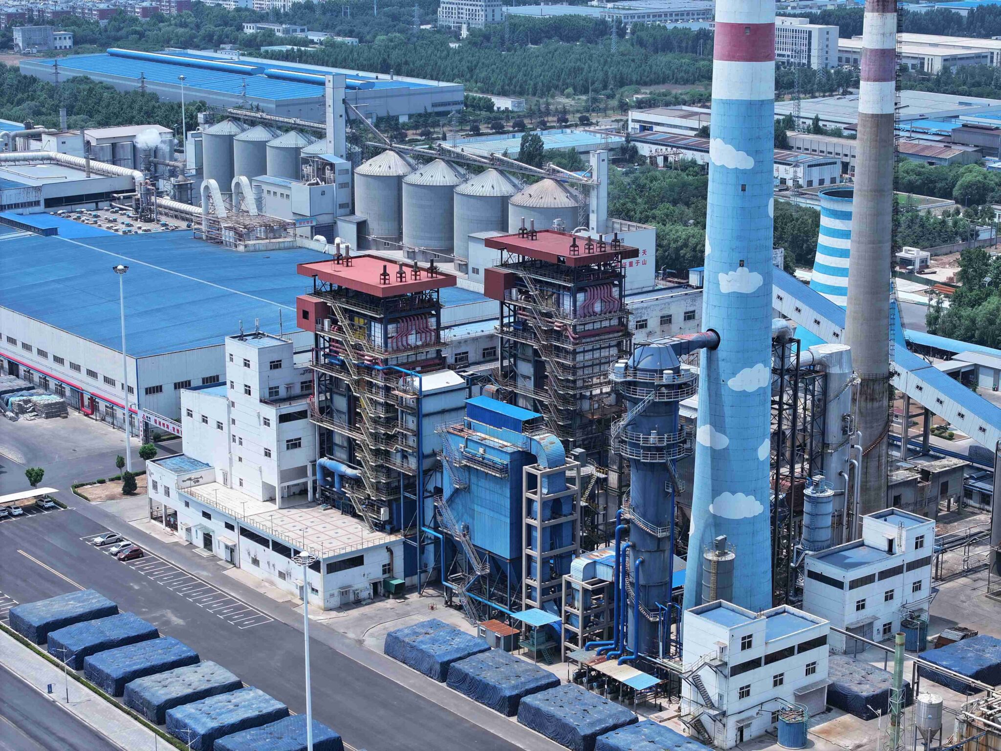
A coal-fired boiler that starts misbehaving rarely gives you a clean, obvious fault code. More often it’s a creeping drop in steam pressure, a flue gas temperature climbing 30°C above where it sat last week, or a sudden spike in coal consumption that your shift operator notices but can’t explain. Left undiagnosed, these symptoms compound — fouled heating surfaces cut thermal efficiency below 80%, forced outages on a 10–20 t/h unit can cost a plant several thousand dollars per day in lost production, and a tube failure from undetected scale or flame impingement turns a maintenance issue into a safety incident.
Troubleshooting industrial coal-fired boilers means working systematically through combustion quality, heat transfer surfaces, draft system balance, and water-side chemistry. Most field problems trace to one of four root causes: incorrect air-to-fuel ratio (target 3–6% O2 at furnace exit), fouled or scaled tubes, draft imbalance across the gas path, or feedwater quality failure. Fix the root cause, not the symptom, and you recover both reliability and thermal efficiency — typically 82–88% on stoker-fired units, 88–92% on CFB designs under optimized conditions.
What makes coal-fired boiler faults genuinely tricky is how they mask each other. A partially blocked air register starves one grate zone, incomplete combustion deposits carbon on the convective bank, that deposit insulates the tubes, flue gas exit temperature climbs, and the operator responds by pushing more coal — which makes every one of those problems worse. Understanding the failure chain, not just the individual fault, is what separates a quick fix from a repeat callout three weeks later.
Diagnosing Poor Combustion Efficiency: Carbon Carryover, Excess Air, and Flame Instability
Poor combustion is almost always the first place fuel money disappears — quietly, steadily, and usually misattributed to coal quality until someone actually checks the ash.
Recognizing the Symptoms Before They Compound
Stack CO readings above 200 ppm are a hard signal that combustion is incomplete. Visible grey or black smoke means the same thing at a glance, though plant operators sometimes normalize it as “just startup behavior.” It rarely is. Check your fly ash and bottom ash loss-on-ignition (LOI): anything above 5% LOI is a red flag that you’re paying for fuel and throwing it out the back end. On a 10 t/h stoker unit burning bituminous coal, that LOI level can translate to a fuel waste in the range of 3–6% of total consumption — the exact figure depends on ash ratio, coal CV, and how much fly ash is recycled back to the furnace.
Unexplained fuel consumption creep is trickier because it often builds over weeks. A boiler consuming 8–10% more coal than baseline to hold the same steam output, without a change in load, almost always points back to combustion degradation or a fouling problem compounding on top of it.
Excess Air Coefficient (Alpha) Management
The target excess air coefficient for a chain-grate stoker sits between 1.25 and 1.35. CFB units are tighter — 1.15 to 1.25 — because the longer particle residence time in the fluidized bed compensates for lower local oxygen. Running significantly outside these bands in either direction costs you: too low and you get incomplete combustion and CO spikes; too high and you’re heating nitrogen you don’t need, dragging stack losses up and flue gas temperature with it.
Your flue gas O2 analyzer is the fastest correction tool you have. At furnace exit, target 3–6% O2. If you’re reading 7–9% O2 consistently, start with the secondary air dampers — trim them back and watch stack temperature and CO simultaneously. If O2 drops but CO rises, you’ve found the real constraint, which is usually fuel bed quality or mixing, not air supply.
Chain-Grate Stoker: Bed Distribution and Grate Mechanics
Uneven coal bed distribution is the most common stoker fault I’ve seen in the field. It shows up as hot streaks on the grate, asymmetric temperatures across the furnace width, and LOI that varies between left-side and right-side ash samples. The fix starts at the coal feeder and coal spreader adjustment — not the combustion air.
Worn grate bars cause air channeling, where combustion air punches through gaps instead of distributing evenly through the bed. You’ll see localized over-firing, clinker formation near those channels, and paradoxically high CO elsewhere. Inspect grate bar wear during every planned outage; replacement intervals vary from 8,000 to 18,000 hours depending on ash abrasiveness and operating temperature.
Grate speed needs to match coal calorific value. Running a 5,500 kcal/kg coal on grate speed settings calibrated for 4,800 kcal/kg coal means the bed burns through too fast, leaving the rear grate section with thin, channeling fuel.
| Coal CV (kcal/kg) | Typical Grate Speed Range (m/h) | Bed Depth Target (mm) | Notes |
|---|---|---|---|
| 4,200–4,600 | 3.5–5.0 | 100–130 | Lower-rank coal, higher ash; watch clinker |
| 4,600–5,200 | 4.5–6.5 | 90–120 | Mid-range; most common industrial coal |
| 5,200–6,000 | 5.5–8.0 | 80–110 | Higher CV; risk of thin bed and air bypass |
| >6,000 | 7.0–10.0 | 70–100 | Adjust undergrate air zones independently |
These ranges shift depending on volatile matter content and coal moisture — wet coal slows the effective burn rate and may require a speed reduction even at the same CV.
CFB-Specific Faults: Bed Temperature and Loop Seal Blockage
A CFB furnace running below 850°C bed temperature will produce measurable CO and unburned carbon regardless of air supply. The combustion kinetics simply don’t work below that threshold. The usual culprits are incorrect bed material inventory, oversized feed coal (poor crushing), or — the one that catches people off guard — a loop seal blockage that’s starving the furnace of returning hot solids.
Loop seal blockage is a leading root cause of low bed temperature in CFB boilers and can cause incomplete combustion even when air supply and fuel feed appear normal.True
The loop seal returns hot circulating bed material from the cyclone back to the furnace. Blockage interrupts this loop, reducing bed mass and heat retention, which drops bed temperature below the 850°C threshold needed for stable combustion — independent of air or fuel conditions.
Bed material segregation — where coarser, denser particles accumulate at the bottom while fines are elutriated — also flattens the temperature profile and reduces cyclone capture efficiency. Check pressure drop across the cyclone: a significant drop from baseline (typically 400–800 Pa depending on unit size) suggests reduced solid loading, pointing back to either low inventory or a cyclone inlet erosion issue.
Pulverized Coal Burner Faults
On pulverized coal (PC) units, classifier wear is the fault that ages quietly. A worn classifier passes coarser particles into the burner stream, and the R90 (residue on 90-micron sieve) climbs from a target of 8–15% toward 25–30% or higher. You’ll see higher LOI in fly ash and sometimes visible unburned carbon on furnace walls opposite the burners.
Primary-to-secondary air ratio imbalance shifts the flame shape and can cause impingement on furnace walls or superheater tubes — a short-term combustion problem that becomes a long-term tube wastage problem. Burner nozzle erosion, particularly on the inner quarl and tip, changes the swirl characteristics and effectively de-tunes the burner without any visible external damage until the damage is already significant.
Corrective Action Matrix
| Symptom | Instrument Check | Mechanical Inspection | Operational Adjustment | Re-Verification |
|---|---|---|---|---|
| High stack CO (>200 ppm) | Flue gas O2 analyzer, CO monitor | Grate bars, air duct dampers | Increase primary air; adjust grate speed | Re-check CO and O2 after 30 min stable load |
| High fly ash LOI (>5%) | Grab sample + lab LOI test | Classifier wear (PC), grate distribution (stoker) | Reduce grate speed or reclassify coal | Weekly LOI sampling for 2–3 weeks post-adjustment |
| Low CFB bed temp (<850°C) | Bed thermocouple array, loop seal ΔP | Loop seal inspection, bed material sampling | Add bed material; increase primary air | Confirm bed temp stabilizes at 850–920°C |
| Visible black/grey smoke | Stack opacity monitor | Coal feed system, burner tips | Adjust excess air; check coal moisture | Stack observation + O2 trend over one shift |
| Unexplained fuel increase | Fuel consumption log vs. steam output | Fouling on heating surfaces, ash LOI | Full combustion audit; tube bank inspection | Efficiency test before and after correction |
Waterside and Steamside Problems: Scale Buildup, Overheating, and Drum Level Instability
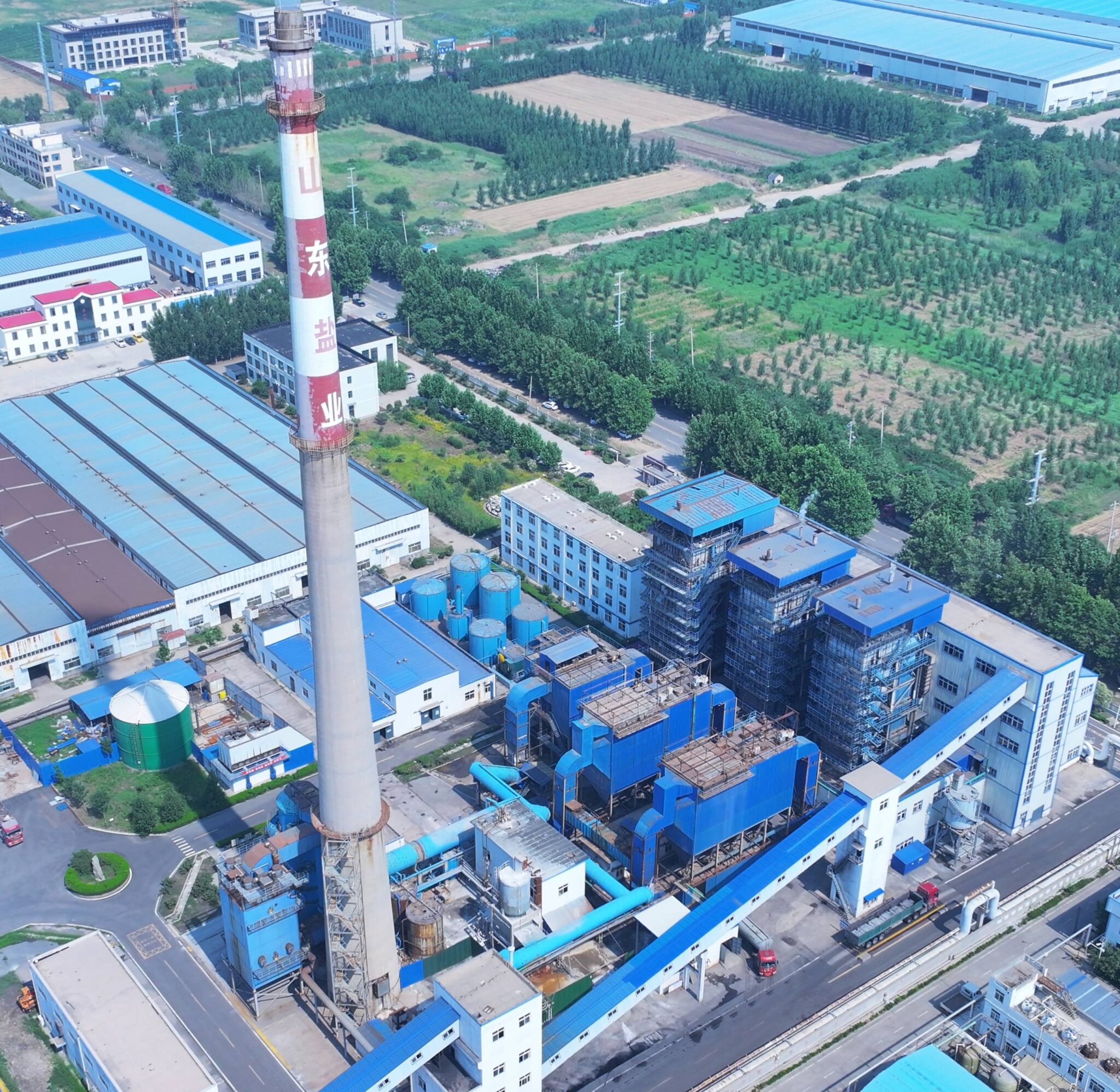
Scale is quiet. It builds over months, you can’t see it from the outside, and by the time your operators notice something wrong — elevated stack temperature, a tube that starts weeping, drum pressure that won’t hold — you’ve already been losing efficiency and stressing metal for a long time. In my experience, waterside failures account for a disproportionate share of unplanned shutdowns on coal-fired units, particularly in regions where makeup water hardness is high and water treatment gets treated as an afterthought.
How Scale Actually Damages Tubes
Calcium carbonate and magnesium silicate are the usual culprits. Both have extremely low thermal conductivity compared to steel — roughly 0.5–2 W/(m·K) versus around 45 W/(m·K) for carbon steel — so even a thin deposit acts as an insulating blanket on the tube’s inner surface. A scale layer as thin as 0.5 mm can raise the tube wall metal temperature by 30–50°C above the design value, depending on heat flux at that location. In high-heat-flux zones near the furnace bottom or adjacent to burner registers, that temperature penalty pushes the tube metal toward the creep range faster than most operators expect. Once creep damage accumulates, you’re not repairing — you’re replacing.
A 1 mm scale deposit on a boiler tube inner wall can raise metal temperature by 60–100°C under high heat flux conditions.True
Thermal resistance of common scale deposits (CaCO3, MgSiO3) is substantially higher than steel; at typical furnace-zone heat fluxes of 150–250 kW/m², even modest deposit thickness creates significant temperature gradients across the tube wall, well-documented in ASME and industry boiler maintenance literature.
What to Measure and When
Feed water hardness after the softener should be below 0.03 mmol/L consistently — not as a spot check once a month, but as a daily logged parameter. If your softener resin is exhausted or your regeneration cycle timing drifts, hardness spikes will go unnoticed until a boiler water sample shows elevated calcium. Boiler water TDS targets typically sit between 1,500 and 3,500 mg/L depending on operating pressure: lower-pressure units (under 1.6 MPa) can tolerate the higher end; once you’re above 2.5 MPa, keep TDS tighter, closer to 1,500–2,000 mg/L. Silica in boiler water deserves its own column on the log sheet — silica volatilizes into steam above certain concentrations and deposits on turbine blades or superheater tubes downstream.
Continuous blowdown rate is not a fixed setting. Calculate it from the ratio of makeup water TDS to the allowable boiler water TDS concentration. If your makeup water runs at 300 mg/L TDS and your target boiler water TDS is 2,400 mg/L, the theoretical blowdown-to-evaporation ratio is roughly 1:7. In practice, account for condensate return quality and intermittent bottom blowdown when setting your continuous blowdown valve position. Operators who never adjust the continuous blowdown across seasons — when condensate return rates drop in winter or makeup water quality shifts — end up either over-concentrating the boiler water or wasting heat.
Drum Level Instability: Swell, Shrink, and the Control System That Gets Confused
Swell and shrink catch new operators off guard every time. When load increases suddenly, steam pressure drops momentarily, the steam-water mixture in the drum expands (swell), and the level reading rises — even though actual water inventory hasn’t increased. A single-element control system sees a rising level and throttles back the feedwater valve, which is exactly the wrong response. The boiler is actually short on water mass. A two-element system adds a steam flow signal to correct this; a three-element system incorporates feedwater flow as well, which is the right approach for units above roughly 20 t/h evaporation capacity or any unit with fast load swings.
Control valve hunting — where the feedwater valve oscillates continuously rather than settling — is a separate problem, usually traced to incorrect PID tuning, a sticky valve actuator, or a transmitter with response lag. Before retuning the PID, verify the level transmitter calibration. Differential pressure-type level transmitters drift with changes in reference leg temperature, especially in outdoor installations during winter. A transmitter showing 50% level when the drum is actually at 60% will confuse any control loop. Calibration checks should happen quarterly at minimum, not only during annual shutdown.
Overheating Fault Tree for Water Tube Units
Not all overheating has the same root cause, and misdiagnosis wastes shutdown time. Work through this systematically:
| Symptom | Most Likely Cause | Distinguishing Check |
|---|---|---|
| Multiple furnace wall tubes overheating | Flame impingement or uneven heat distribution | Check burner alignment, coal particle size distribution |
| Single tube or tube row overheating | Scale blockage or partial flow starvation | UT thickness measurement; cut tube and inspect bore |
| Superheater outlet temperature high across all tubes | Excess air or flue gas temperature elevated | Check O2 at furnace exit; target 3–6% O2 |
| Superheater outlet temperature high on one side | Steam flow maldistribution | Check header drain valves; inspect tube ID for deposits |
For high-pressure units above 2.5 MPa, superheater tube metal temperature exceedance is the faster killer. Design metal temperatures for common superheater materials like T91 or 12Cr1MoV allow relatively narrow margins, and sustained operation even 20–30°C above the design metal temperature accelerates oxidation and creep. Install thermocouples on superheater outlet headers if they aren’t already there — this is cheap insurance.
Inspection and Chemical Cleaning
Ultrasonic thickness measurement on water wall and superheater tubes should be done at every planned outage, with particular attention to the bottom third of furnace water walls and the first few rows of the superheater. Document measurements with location maps so you can track thinning trends over time rather than comparing each outage in isolation.
Acid cleaning — typically 5–8% HCl with a corrosion inhibitor such as urotropine — is the standard descaling method when deposits exceed roughly 200–300 g/m². Before acid cleaning, confirm inhibitor concentration is adequate (follow the inhibitor supplier’s specification; under-inhibited acid will attack the tube base metal). Maintain acid temperature in the 50–60°C range for effective scale dissolution without excessive inhibitor degradation. After cleaning, passivate with a sodium nitrite or similar solution, flush thoroughly, and check the waste acid pH and iron content to confirm cleaning completeness. Keep personnel away from vent points during the cleaning — HCl fumes in a boiler room are not a minor inconvenience.
Borescope inspection of superheater and reheater tubes is worth doing every 2–3 outage cycles even when external measurements look acceptable. Deposits on the steam side are invisible to UT from the outside and can build silently until a tube plugs or bursts.
Furnace Pressure Fluctuations, Slagging, and Fouling on Heat Transfer Surfaces
Ash behavior is where coal combustion gets genuinely complicated. Unlike gas or oil firing, coal leaves a physical residue that interacts with every surface in the boiler — and the composition of that ash varies enough between coal sources that what works fine for one fuel specification can cause serious fouling or slagging problems with the next delivery. Getting this right requires understanding both the draft system mechanics and the coal chemistry.
Furnace Draft Control and Fan Faults
Balanced draft systems are standard on most industrial coal-fired boilers above roughly 20 t/h, and the typical design target is -20 to -50 Pa at the furnace top. That’s a narrow band. Drift toward positive pressure — even briefly — causes flame rollout at inspection doors, damaged seals, and combustion gases leaking into the boiler house. Operators sometimes underestimate the hazard because the first sign is just a little heat shimmer around a door gasket, but sustained positive furnace pressure accelerates seal degradation and creates real personnel risk.
Negative pressure running too deep has the opposite problem: excess cold air infiltrates through every small gap in the casing, the flue gas O2 climbs well above the 3–6% target range, and you’re paying to heat atmospheric nitrogen rather than generate steam. Efficiency takes a measurable hit.
ID fan blade erosion is common and often underdiagnosed. Fly ash concentration in the flue gas, especially with high-volatile coals or poor combustion, slowly erodes impeller blades asymmetrically. The signature is increasing vibration — ISO 10816 velocity limits for fans in this service are typically 4.5–7.1 mm/s RMS depending on mounting class, and once you’re trending past the alert threshold, you’re looking at weeks, not months, before forced shutdown. Check blade wear patterns at every planned outage; uneven erosion means imbalance that accelerates bearing damage faster than most maintenance schedules account for. Inlet vane actuator failures and duct leakage points are also worth a systematic walkthrough when draft control becomes erratic — a failed actuator that locks vanes at partial open is easy to misread as a controls issue.
Slagging: Reading the Coal’s Ash Chemistry
Coal ash with a base-to-acid ratio (B/A) above 0.4 carries significantly elevated slagging risk compared to low-ratio coals.True
The B/A ratio, calculated from the relative proportions of basic oxides (Fe2O3, CaO, MgO, K2O, Na2O) to acidic oxides (SiO2, Al2O3, TiO2) in coal ash, is a well-established empirical predictor of slagging tendency used in boiler combustion engineering.
Ash fusion temperature data from your coal supplier is worth more than it often gets credit for. If the initial deformation temperature (IDT) is below your furnace exit gas temperature, you’ve got molten or semi-molten ash contacting furnace walls — slagging starts there. High-slagging coals need shorter inspection intervals (every 500–700 operating hours as a rough guide, depending on severity) and aggressive online acoustic soot blower scheduling. Letting a slag bridge build across a furnace nose arch or roof is a different order of problem than ordinary fouling — removal can require cold shutdown and manual chipping.
Distinguish slagging from high-temperature corrosion carefully. Slagging is primarily mechanical blockage. Corrosion under slag deposits — driven by sulfate and chloride chemistry — attacks tube metal and is invisible until you remove the deposit and find wall thinning. Both warrant attention, but the inspection and remediation protocols are different.
Convection Pass Fouling and Soot Blower Management
Bonded deposits on superheater and economizer tubes behave very differently from loose ash accumulation. Loose ash shifts with soot blowing and shows up in hoppers. Bonded deposits are sticky, sulfate-rich, and resist blowing — they build tube-to-tube bridging over weeks. The practical diagnostic is straightforward: monitor flue gas temperature rise across each heat transfer bank during steady load. A bank that’s absorbing less heat than design shows up as a higher flue gas temperature entering the next section. Trending this over time tells you where fouling is active before it becomes a cleaning emergency.
Soot blowers in the convection pass typically require 0.8–1.2 MPa saturated steam to be effective — below that, the lance velocity drops and you’re wetting deposits rather than removing them, which often makes bonding worse. Rotary soot blowers suit furnace and lower-temperature zones; retractable long-retract units are necessary for high-temperature superheater regions where lance dwell time needs to be minimized to protect the lance tube itself. Valve gland leaks and lance tube bowing are the two most common maintenance failures — bowed lances bind in the drive mechanism and the failure mode is usually a sheared drive pin at the worst possible time.
Air Preheater Cold-End Corrosion
Ljungstrom and tubular air preheaters both suffer cold-end corrosion when flue gas metal temperatures drop below the sulfuric acid dew point, which for coals with 1–3% sulfur content typically falls in the 120–145°C range depending on moisture, SO3 concentration, and excess air level. Running metal temperature even 10°C below dew point consistently leads to rapid corrosion of the cold-end elements — tubular units lose wall thickness, Ljungstrom baskets develop through-pitting that creates air-to-flue-gas leakage.
Leakage detection via CO2 balance across the unit is a practical field method: measure CO2 concentration in both air and flue gas streams at the preheater inlet and outlet. Rising CO2 in the combustion air stream indicates flue gas short-circuiting. That leakage also inflates the apparent O2 reading at the furnace, which can fool the combustion control system into thinking it’s running with correct excess air when it isn’t — a subtle efficiency penalty that compounds quietly over time.
Refractory and Casing Failures: Hotspot Detection, Brick Deterioration, and Seal Leaks
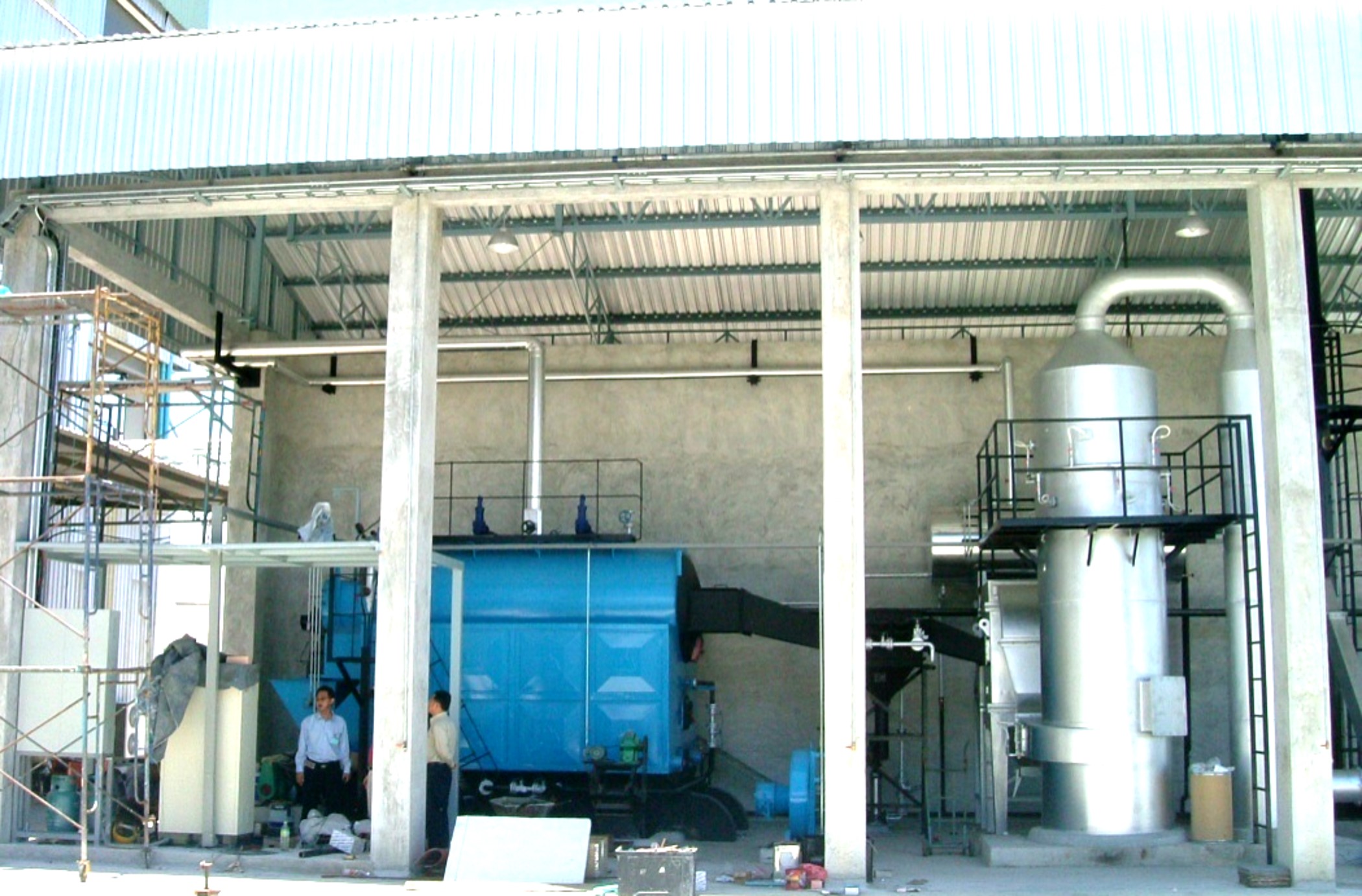
Refractory failures rarely announce themselves dramatically. More often, you lose a few percent of efficiency over weeks, your draft fans start working harder, and someone eventually notices the casing is hot enough to be uncomfortable to stand near. By then, the damage is usually deeper than a surface patch can fix.
Refractory Material Zones and Why They Fail Differently
Coal-fired boilers use several refractory types matched to specific thermal and mechanical conditions. Dense firebrick lines furnace floors and lower sidewalls — these see direct flame radiation, slag contact, and mechanical abuse from clinker removal. Castable refractory fills corner seals, burner throats, and access openings where complex geometry makes brick impractical. In CFB units, ceramic fiber modules are common on upper furnace walls and roof panels where temperatures are lower but thermal cycling is frequent.
Each material fails through a different mechanism. Dense firebrick spalls from thermal shock — especially if cold air leaks contact hot brick surfaces during load swings. Castable anchors corrode or the castable itself cracks if the original dry-out schedule was rushed. Ceramic fiber compresses over time, losing insulation value without visibly cracking, which is why you can have a surface that looks intact but runs 40–50°C hotter than it should.
Hotspot Detection: Don’t Guess, Scan
Infrared thermography on boiler casing panels during normal operation is the most practical diagnostic method — and still underused at a surprising number of plants. A calibrated IR camera scan of the full casing exterior, done quarterly or after any fuel quality change, shows hotspot patterns that correlate directly to refractory thinning or loss behind the panel.
The working threshold most experienced boiler engineers use: casing panel surface temperatures above roughly 80°C indicate meaningful refractory loss and should be logged for planned outage repair. Temperatures above 120°C on a panel — particularly if the spot is growing between scans — warrant load reduction and accelerated repair scheduling. If you see glowing or discolored casing metal, that’s past the point of discussion.
CFB-Specific Refractory Problems
CFB boilers have a particular refractory vulnerability that stoker-fired units don’t: erosion at the cyclone inlet. Particle-laden flue gas enters the cyclone separator at velocities typically in the 15–25 m/s range depending on unit capacity and cyclone geometry. At those velocities, even well-anchored castable erodes — plan on inspecting cyclone inlet wear liners every 8,000–12,000 operating hours, depending on bed material characteristics and coal ash abrasiveness. Some operators extend this by applying silicon carbide-based wear-resistant castable at the inlet throat, which holds up considerably better than standard high-alumina castable in abrasive service.
Loop seal refractory cracking is a separate issue, driven by thermal cycling during startup and shutdown. The loop seal sees relatively cool fluidizing air during cold startup and then heats rapidly once the bed ignites. If the refractory wasn’t cured correctly at commissioning, or if the plant does frequent cold starts, cracking appears at anchor tie-in points within the first few thousand hours.
Air Infiltration: A Hidden Efficiency and Control Problem
A 1% increase in air infiltration through casing leaks raises flue gas volume, increases induced draft fan power consumption, and dilutes measured flue gas O2 — causing the combustion control system to misread actual excess air levels.True
Cold tramp air entering downstream of the furnace adds volume to the flue gas without contributing to combustion. The O2 analyzer reads this diluted mixture and interprets it as higher excess air than actually exists in the combustion zone, often causing the control system to reduce combustion air and worsen burnout.
This is the one that catches plants off guard. Casing seal leaks near the economizer or air preheater section are especially problematic because the O2 probe sits downstream. The control system sees elevated oxygen, assumes combustion air is already sufficient or excessive, and may trim primary air — which actually degrades combustion. You end up with higher carbon carryover and higher fan power simultaneously. Not obvious from the DCS trend screens unless you’re specifically looking for it.
Repair Decision Framework
| Casing Surface Temp | Estimated Heat Loss Increase | Recommended Action |
|---|---|---|
| Below 80°C | Negligible | Monitor; include in next planned inspection |
| 80–120°C | 0.5–1.5% depending on affected area | Log, prioritize repair at next scheduled outage |
| 120–180°C | 1.5–3% or higher | Reduce load if possible; accelerate outage planning |
| Above 180°C or visible discoloration | Significant; structural risk possible | Evaluate emergency shutdown; consult boiler OEM |
These thresholds assume standard carbon steel casing panels. Stainless-lined panels tolerate somewhat higher surface temperatures before creep risk, but the refractory loss driving those readings is still unacceptable.
Castable Repair: Cure Schedule Is Not Optional
One of the most common mistakes during repair outages is pressure to return the unit to service before castable refractory has been properly dried out. Green castable — even material that feels dry to the touch after 24 hours — retains chemically bound moisture that converts to steam if heating is too aggressive. The result ranges from surface cracking to violent spalling that voids the repair entirely.
A proper dry-out firing curve holds heat-up rate to no more than 50°C per hour through the critical range up to around 300°C, with mandatory hold periods at roughly 100–120°C and again at 250–300°C to allow moisture to escape gradually. Total dry-out for a significant castable repair typically runs 24–48 hours minimum before normal operating temperatures are approached. Plants that skip or shorten this step reliably spend more time on refractory repairs over the unit’s lifetime than plants that do it right once.
Feed Water System, Deaerator, and Auxiliary Equipment Fault Diagnosis
The boiler itself gets all the attention. In practice, roughly half the forced outages I’ve seen on coal-fired plant trace back to something upstream of the drum — the deaerator, the feed pumps, the economizer, or a misbehaving control valve. These systems are less dramatic than a furnace slagging event, but their failure modes are quieter and more insidious, and by the time the boiler shows symptoms, the damage is usually already done.
Deaerator Performance: Dissolved Oxygen Is Not Optional
Target dissolved oxygen in boiler feed water is below 7 ppb (0.007 mg/L) — that figure applies across virtually all medium- and high-pressure industrial boilers. Getting there consistently requires correct steam sparging flow, adequate residence time in the storage tank, and stable inlet water temperature. When DO climbs — and it will if you’re not sampling regularly — the first suspects are a failed or undersized steam control valve that’s letting cold makeup water surge in faster than the heating steam can handle it, or a partially blocked sparger nozzle that’s channeling steam rather than distributing it uniformly through the tray stack or spray head.
A useful field check: measure the vent steam flow from the deaerator head. If it’s essentially zero, the unit is not sweeping dissolved gases. There should always be a small, visible vent plume. No plume means no deaeration, regardless of what the temperature gauge says.
Feed Water Pump Cavitation and Seal Failures
Cavitation on boiler feed pumps is frequently misread as a mechanical problem when it’s actually a process problem. NPSH margin erodes fast when feed water temperature creeps toward saturation — especially in summer months when hotwell temperatures drift upward — or when suction strainer differential pressure climbs unnoticed past 0.05–0.08 bar, which takes maybe three months of continuous operation without a check on strainers handling moderate ash contamination from a condenser leak event.
The audible cavitation signature (crackling, inconsistent) is sometimes confused with bearing noise. Pull the suction pressure reading and compare against the pump’s NPSH required curve at current flow. If margin is under 0.5 m, the pump is already in trouble regardless of whether it’s making noise yet.
Mechanical seal leakage is usually a maintenance-interval problem, not a specification problem. Dry running during any transient startup — even briefly — will destroy a seal. Minimum flow bypass valves deserve more respect than they get; a stuck-closed bypass during low-demand operation kills pumps fast.
Economizer Acid Condensation and Oxygen Pitting
For high-sulfur coals (sulfur content above roughly 1.5%), the acid dew point of the flue gas can sit between 120–150°C depending on actual SO₃ concentration and moisture. If metal temperature at the economizer exit tubes drops below this range — which can happen during low-load operation or with excessive excess air — sulfuric acid condenses on tube surfaces. The corrosion is rapid and localized, appearing as pitting with a characteristic orange-brown staining pattern around the attacked area.
Oxygen pitting on the same tubes comes from a different direction: inadequate deaeration upstream. The two failure modes can occur simultaneously, and they do.
Maintaining economizer exit flue gas metal temperature above the acid dew point prevents sulfuric acid condensation corrosion on economizer tubes.True
Acid dew point condensation requires metal surface temperature to fall below the SO₃/H₂O dew point. Keeping metal temperature 10–15°C above the calculated acid dew point is standard practice to prevent this corrosion mechanism.
Steam Drum Internals and Carryover Diagnosis
Steam moisture carryover is rarely obvious until downstream equipment — typically a turbine or a process heat exchanger — starts accumulating silica deposits or shows unexpected corrosion patterns. Target steam dryness is above 99.5%. Worn chevron dryers or damaged cyclone separators inside the drum will push moisture carryover up quietly over months.
The most reliable diagnostic is a sodium tracer test: measure sodium concentration in the steam versus the drum water. Silica balance across the drum works similarly and is useful when a sodium test isn’t practical. Both methods give you a carryover fraction without requiring you to open the drum.
Blowdown System and TDS Control
Continuous blowdown systems with flash tank heat recovery are standard on most Taishan Group boiler packages above roughly 10 t/h capacity. Common field problems include flash tank pressure control valves hunting (usually a positioner calibration issue or oversized valve trim), tube blockage in the blowdown heat exchanger from calcium carbonate scaling when softener resin exhaustion isn’t caught early, and conductivity-based TDS controllers that drift over time and either over-blow — wasting heat and treated water — or under-blow and allow TDS to climb toward drum damage territory.
Calibrate the conductivity transmitter against a lab sample at least once a month. It’s a five-minute job that most plants skip.
Instrumentation Faults That Masquerade as Process Problems
Blocked impulse lines on pressure transmitters are responsible for a surprising share of apparent drum level instability. In cold climates, condensate in an untraced impulse line will freeze; in dusty environments, ash finds its way into instrument taps left open during maintenance. Either way, the control system sees a false signal and responds accordingly — swinging feed water flow in ways that stress the drum and confuse operators.
Thermocouple drift in high-temperature zones is real and consequential. Type K thermocouples above 900°C drift measurably within 6–18 months depending on cycling frequency and atmosphere. A thermocouple reading 20°C low on a superheater outlet means the control system is running metal temperatures hotter than it knows. Scheduled replacement or cross-checking against a portable reference is not optional on superheated steam lines.
Control valve positioner hysteresis on the feed water flow valve is worth checking any time you see oscillating drum level that doesn’t track a clear process cause. A valve that lags 3–5% on stroke produces level swings that look exactly like a process disturbance.
Emissions Exceedance Troubleshooting: SO2, NOx, and Particulate Control System Faults
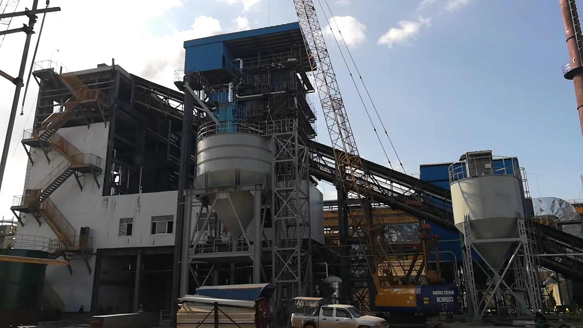
Emissions exceedance is the fault category most likely to get your plant shut down — not just fined, but physically locked out by regulators. In export markets across Southeast Asia, the Middle East, and sub-Saharan Africa, permit limits are tightening fast, and EPC contracts increasingly carry performance-guarantee clauses tied to stack emissions. Getting this wrong has contractual consequences, not just environmental ones.
Electrostatic Precipitator Faults
ESP problems split roughly into three categories: mechanical, electrical, and thermal. Rapping system failures are the most common mechanical cause of particulate exceedance. When a rapper motor seizes or a rapper timing controller drifts, ash accumulates on collecting plates instead of falling into hoppers — and eventually re-entrains into the gas stream. Dust concentration at the stack can spike 3–5× before anyone notices the rapper is dead, because the effect builds gradually over hours. Check rapper impact force with an accelerometer if you suspect reduced stroke; worn anvils are a surprisingly frequent culprit that gets ignored during planned maintenance.
On the electrical side, a drop in secondary current in a specific field — say, field 3 of 4 dropping from 400 mA to under 100 mA without voltage collapsing — usually points to a broken or slack electrode wire causing a localized short or arc suppression. Ash bridging between discharge and collection electrodes produces a similar signature. Pulling the field out of service and inspecting through the access door during a short outage is the only reliable confirmation.
Inlet gas temperature matters more than most operators realize. The design window is typically 120–180°C. Below 120°C you risk acid condensation on electrodes, which causes corrosion and dramatically increases resistivity of the ash cake. Above 180°C, the ash resistivity drops into the range where back-corona becomes problematic. If your air preheater is fouled or bypassed, check ESP inlet temperature before assuming the ESP itself is the problem.
Bag Filter Faults
A slow, steady rise in differential pressure — say 200 Pa per week above baseline — typically means bags are blinding rather than a sudden pulse-cleaning failure. Check compressed air supply pressure at the pulse valves first (usually needs to hold 0.4–0.6 MPa consistently); a partially closed isolation valve upstream is embarrassingly common. If pulse pressure is fine, you likely have bags that have absorbed moisture and caked permanently, or the wrong bag material for your coal ash chemistry.
Bag material selection is not trivial. Standard polyester felt works up to around 130°C and is adequate for low-sulfur coals with dry ash. For flue gas above 150°C, or where SO3 concentration is elevated, PTFE-membrane bags rated to 260°C are the practical choice — they cost roughly 4–6× more per bag, but a single re-bag event lost to acid hydrolysis will cost far more. Coal with high abrasive silica content also demands a woven substrate rather than needle-felt; abrasion failure at the bottom third of the bag is diagnostic of this mismatch.
Wet FGD Faults and SO2 Exceedance
WFGD systems fail at SO2 removal for a narrower set of reasons than people expect. Limestone slurry particle size is one that gets neglected after commissioning: the grind spec is typically 90% passing 44 microns, and if the ball mill is worn or the classifier is drifting, particle size creeps up, reactivity drops, and SO2 slips through even with correct pH.
Absorber pH control between 5.0 and 5.8 is the primary day-to-day handle. Below 5.0, gypsum scaling accelerates inside spray headers; above 5.8, CaCO₃ utilization drops and you waste limestone. If your pH probe is reading stable but SO2 is rising, suspect a failed probe rather than a process shift — these probes foul in slurry service and should be on a weekly calibration check, not monthly.
Mist eliminator plugging is a slower failure mode but causes SO2 exceedance indirectly: when droplet carryover increases, you’re essentially carrying unscrubbed slurry droplets past the measurement point, and the CEMS wet-scrubber on the stack may also be affected. Washing frequency on mist eliminators in high-chloride slurry environments should be daily, not the twice-weekly default that most startup procedures specify.
Gypsum dewatering belt or centrifuge blockage raises absorber liquid density, which eventually reduces mass transfer efficiency. The warning sign is gypsum cake moisture above 12–15%; if you’re seeing wet cake, your dewatering system is underperforming before the density problem becomes acute.
Low-NOx Combustion System Faults
OFA (over-fire air) port blockage is the leading cause of NOx staging loss in stoker and pulverized-coal boilers. Ash sintering inside OFA ports is more common than it should be — usually a result of local reducing atmospheres near the ports during low-load operation. If your NOx is creeping up over weeks, inspect OFA port openings physically, not just the damper position indication.
For SNCR systems, urea injection nozzle plugging is the classic failure mode. Urea crystallizes at nozzle tips during low-flow periods or during brief shutdowns where the purge sequence doesn’t complete. The fix is straightforward — automated water purge on shutdown — but many plants commission SNCR without it. SCR catalyst differential pressure rising beyond 200–300 Pa above baseline indicates either ash plugging between catalyst channels or, in severe cases, sulfate poisoning of the catalyst surface. Poisoning is irreversible on that layer; plugging can often be cleared with soot blowing if caught early.
CEMS Calibration Faults
A CEMS system reading within specification guarantees actual stack emissions compliance.False
CEMS measures a sample extracted from the stack, not the full stack gas. Probe filter blockage, moisture analyzer drift, and sample line condensation can all cause readings to lag or misrepresent actual emission concentrations, even when the instrument itself passes its internal calibration check.
Zero and span drift exceeding 2% of full scale is the regulatory threshold in most permit frameworks, but in practice, a moisture analyzer failure is more operationally dangerous because it corrupts the dry-basis conversion applied to all pollutant readings simultaneously — SO2, NOx, and O₂ all shift together, which can mask exceedance across the board. If your O₂ reading suddenly looks better than normal and you haven’t changed combustion settings, suspect the moisture analyzer before congratulating the operators.
Probe filter blockage causes reading lag: the system shows historical conditions while actual emissions have already changed. On coal boilers with high-ash flue gas, ceramic filter elements in the probe need inspection at least quarterly.
Emergency Response When Limits Are Exceeded
The sequence matters. Load reduction should be the first action — dropping to 70–80% MCR typically reduces all three pollutants within 15–30 minutes while the control team diagnoses the root cause. Parallel to that, document: timestamp, parameter values, actions taken. In most export permit frameworks, self-reported exceedances with documented corrective action are treated significantly more leniently than exceedances discovered during a regulatory inspection.
Temporary corrective measures — increased lime or urea injection, OFA adjustment, emergency bag filter bypass to a secondary collector — should be pre-planned in the plant’s emissions contingency procedure, not improvised under pressure. Regulators in most markets want to see that a written contingency plan exists. If you’re commissioning an EPC project in a new market, get that document drafted before first fire, not after the first exceedance notice arrives.
Planned Maintenance Intervals, Shutdown Inspection Checklist, and Spare Parts Strategy
Troubleshooting is reactive. A well-run plant tries to stay ahead of the fault, not chase it. The sections above cover how to diagnose problems once they appear — this one is about reducing how often they appear in the first place, and making sure that when a shutdown does happen, it’s scheduled rather than forced.
Maintenance Interval Framework
Daily operator rounds are the foundation. Every shift should log furnace draft, steam pressure, drum level swing, flue gas temperature at economizer outlet, and feed water pH. Not because every reading will be abnormal — most won’t be — but because trending is how you catch a slow-moving problem before it becomes an emergency. A flue gas exit temperature creeping up 3–4°C per week usually means fouled economizer tubes, and that’s a cleaning job, not a tube replacement. Catch it at week three; miss it for two months and you’re looking at a 6–9% efficiency penalty and a possible unplanned outage.
Weekly reviews should pull those logged parameters into trend charts. Feed pump discharge pressure, soot blower differential pressure, ID/FD fan current draw — these are the early indicators that rotate into monthly attention items.
Monthly minor inspections cover the mechanical wear items: grate bars for warping or broken segments (especially on chain-grate and traveling-grate stokers operating above roughly 900°C bed temperature), burner tip condition on igniter assemblies, soot blower nozzle wear and rotation check, and a manual lift test on safety valves. That last one gets skipped more often than it should. A safety valve that hasn’t been lifted in 90 days is not a safety valve you can trust.
Annual major overhaul scope for an industrial coal-fired water tube boiler typically runs 10–18 days, depending on unit size and accumulated condition. Anything shorter usually means something got deferred.
Annual Shutdown Inspection Priorities
Tube thickness survey using ultrasonic UT across the high-heat-flux zones — furnace waterwall tubes, superheater outlet legs, and any area with known ash impingement — should be non-negotiable. Minimum acceptable wall thickness is set against the original design calculation; a 15–20% wall loss in a localized area warrants replacement, not just monitoring. Refractory condition mapping follows: photograph every panel, mark any spalling, cracking at expansion joints, or anchor corrosion. A small breach in the furnace crown that looks cosmetic will pull combustion gas into the casing insulation and you’ll have a hotspot within one operating season.
Rotating equipment bearing replacement on ID/FD fans and feed pumps should follow a fixed interval — typically every 18,000–25,000 operating hours depending on bearing size and operating temperature — rather than waiting for vibration alarms. Pressure vessel NDE per whichever code governs the installation (ASME Section I, EN 12952, or GB/T 16508 for Chinese-manufactured units) needs a certified third-party inspector, and the certificates must carry full traceability to the inspector’s credentials. Insurance underwriters and local regulatory bodies will ask for these.
Spare Parts Inventory Matrix
| Class | Stock Location | Typical Items | Logic |
|---|---|---|---|
| A — Stock on-site | Plant storeroom | Grate bars, igniter electrodes, pressure transmitters, sight glass assemblies | Failure stops production; lead time exceeds acceptable downtime |
| B — Regional warehouse | Distributor or service hub, 2–5 day delivery | Feed pump mechanical seals, ESP discharge electrodes, control valve actuators | Moderate lead time; failure causes degraded operation |
| C — Order on demand | Factory or specialist supplier | Steam drum internals (chevron separators, baffles), superheater header plugs | Long lead time acceptable; low failure frequency |
Parts strategy is really a risk calculation. A grate bar costs almost nothing relative to an unplanned 72-hour outage during peak production season. Keep them in stock.
Condition Monitoring Tools
Vibration monitoring on ID/FD fans and the main feed pump is the most cost-effective predictive tool for a coal-fired unit. A $2,000–4,000 portable vibration analyzer pays for itself the first time it catches an imbalance fault before a bearing seizure takes the fan offline. Infrared thermography of the casing, electrical panels, and ESP bus sections should be done quarterly — thermal cameras now rent cheaply enough that there’s no good reason to skip it. Online flue gas analysis (O2, CO, SO2 as a minimum) provides the combustion feedback loop. Boiler water chemistry trending — pH, conductivity, dissolved oxygen, silica — closes the loop on waterside risk.
Continuous online flue gas O2 monitoring reduces excess air losses and improves thermal efficiency by 1–3 percentage points compared to manual spot-check regimes.True
This range is consistent with published combustion optimization studies and field experience: reducing excess air from a typical uncontrolled 40–60% down to a target 20–25% (roughly 3–6% O2) eliminates avoidable stack heat losses, with actual gains depending on coal type, unit design, and baseline control discipline.
Service Support and Documentation
For overseas EPC projects, remote diagnostic capability matters more than most clients anticipate at contract stage. A data logger feeding SCADA with 15-minute trending on 30–40 key parameters allows remote analysis between scheduled site visits — catching a developing problem via email is far cheaper than an emergency flight and a reactive repair under time pressure. Taishan Group’s overseas service model builds in annual commissioning-anniversary inspections, localized operator training in the plant’s working language, and a defined escalation path for urgent faults.
Documentation is not optional for insurance or regulatory compliance. The boiler log book, safety valve test records, water treatment logs, and all NDE certificates should be archived in a single traceable folder — physical and digital. An inspector arriving for a statutory examination and finding incomplete records can condemn a unit to extended shutdown pending re-inspection. That’s a weeks-long production loss for a paperwork failure, which is the most avoidable kind.
Frequently Asked Questions About Coal-Fired Boiler Troubleshooting
What is the most common cause of coal-fired boiler tube failure, and how can it be prevented?
Scale buildup is the leading culprit, by a wide margin. Even 1 mm of calcium carbonate scale on the waterside surface can raise tube wall temperature by 50–80°C above the design value — enough to push you into the creep range on carbon steel tubes operating at moderate pressure. The allowable deviation before damage risk becomes critical is roughly 15–20°C above design metal temperature, so the margin disappears fast. Oxygen pitting is the second major mechanism, typically caused by inadequate deaeration or a failed chemical dosing pump that no one noticed for two weeks. Dissolved oxygen above 0.05 mg/L at the feedwater inlet will pit tube surfaces within months under cycling load conditions. Flame impingement tends to be less frequent but far more dramatic — it usually appears after a burner register adjustment goes wrong or coal sizing drifts coarser than the stoker is tuned for, causing the flame front to extend and contact the waterwall directly.
Prevention comes down to three non-negotiables: maintain feedwater hardness below 0.03 mmol/L, run the deaerator at proper temperature (usually 104–107°C at atmospheric pressure), and inspect tube thickness ultrasonically every major outage. Don’t skip the tube-to-drum weld zones — that’s where oxygen pitting tends to concentrate.
How do I know if my boiler is running at optimal combustion efficiency without expensive instrumentation?
You don’t need a full flue gas analyzer system to get a reasonable read. Stack smoke color is a useful first indicator — light gray or nearly invisible means combustion is reasonably complete; persistent black or dark brown smoke points to unburned carbon, usually from excess fines in the coal or insufficient undergrate air. A thermocouple at the economizer outlet gives you stack temperature: above 220°C on a well-fouled unit suggests poor heat transfer and real efficiency loss; below 160°C you risk acid dewpoint corrosion if sulfur content is meaningful.
A portable O2 analyzer — a basic electrochemical cell type runs $300–600 and pays for itself in one week — gives you flue gas oxygen at the furnace exit. Target 3–6% O2 for complete combustion without flooding the system with cold excess air. Below 2%, you’re likely producing CO. Above 8–9%, you’re heating the atmosphere instead of the process.
Stack smoke color alone is sufficient to confirm optimal combustion efficiency in a coal-fired boiler.False
Smoke color indicates gross combustion problems but cannot confirm O2 levels, CO production, or unburned carbon carryover. A portable O2 analyzer is needed for any reliable efficiency assessment.
What coal quality parameters most affect boiler reliability, and how should I adjust operations when coal specification changes?
Calorific value (CV) drives thermal load — drop from a 5,800 kcal/kg design coal to 4,800 kcal/kg and you’ll need roughly 20% more fuel feed rate to hold the same steam output, which stresses the grate drive and ash handling system. High ash content (above 25–30%) increases slagging risk and can overwhelm ash conveyors if they weren’t sized for it. High moisture (above 15% for stoker units) slows ignition and can destabilize the flame, particularly problematic in wet seasons when run-of-mine coal arrives wetter than the spec sheet promised. Sulfur above 1.5% accelerates cold-end corrosion and will push SO₂ above most regional emission limits unless the desulfurization system was sized for it.
When the coal spec changes, the minimum response is: re-check undergrate and overfire air damper positions, re-calibrate the fuel feeder speed, and pull a combustion gas sample within the first 4 hours of operation on the new batch.
How long does it take to repair refractory in a CFB boiler cyclone, and can it be done during partial load operation?
Cyclone refractory repair typically takes 5–10 days for a single cyclone, depending on the extent of erosion and whether anchor studs need replacement. That range assumes you have material on-site — castable delivery lead times in some regions add another 1–2 weeks if not pre-stocked. Curing adds mandatory time: most high-alumina castables require a controlled heat-up curve over 24–48 hours before returning to full load.
Partial load operation with a damaged cyclone is not a good idea in practice. Reduced cyclone efficiency means higher particulate carryover to the convective pass, which accelerates erosion of superheater tubes and throws off bed inventory balance. In my experience, operators who try to “limp through” on a cracked cyclone typically end up with a forced shutdown that lasts longer than the original repair would have.
What is the difference between troubleshooting a CFB boiler versus a chain-grate stoker boiler?
| Fault Area | CFB Boiler | Chain-Grate Stoker |
|---|---|---|
| Combustion instability | Bed temperature uniformity, fluidization air distribution, particle size control | Grate speed, coal layer depth, undergrate air zone balance |
| Tube erosion | High erosion from circulating bed material, especially at bends | Low erosion risk; flame impingement more relevant |
| Efficiency range | 88–92% optimized; sensitive to bed inventory | 82–88%; sensitive to coal sizing and grate condition |
| Slagging | Less common in furnace; fouling in cyclone and back-pass more typical | Clinker formation on grate is frequent with high-fusion-temp ash |
| Refractory maintenance | Cyclone lining is a recurring maintenance item | Simpler refractory; rear arch and front arch are common wear points |
CFB units carry more instrumentation and demand more rigorous process control. Stoker units are more forgiving operationally but more sensitive to coal sizing inconsistency. For a buyer evaluating which type to specify, the decision usually comes down to fuel flexibility, steam capacity, and in-house maintenance capability.
Can a coal-fired boiler be retrofitted to co-fire biomass, and what new faults should be expected?
Yes, co-firing is technically feasible for both stoker and CFB designs, though the ease and cost vary substantially. Stoker boilers can typically accept 10–20% biomass by heat input with relatively modest modifications to the fuel feed system. CFB boilers handle higher co-firing ratios, sometimes up to 30–50%, but require attention to bed material management since biomass ash has different sintering characteristics.
New fault modes to anticipate: alkali-induced fouling (biomass ash is rich in potassium and sodium, which form sticky low-melting deposits on superheater surfaces), accelerated chlorine corrosion in the superheater and economizer zones, and increased risk of bridging or plugging in biomass fuel hoppers — especially with fibrous materials in humid climates. Flame behavior also changes; biomass volatile content is much higher than coal, so the combustion zone shifts forward and flame impingement risk on waterwalls increases if air distribution isn’t rebalanced.
Any coal-fired stoker boiler can co-fire biomass up to 50% heat input without design modification.False
Co-firing ratios above 15–20% on stoker units typically require fuel feed system upgrades, revised air distribution, and superheater material review. Higher ratios may not be feasible without structural redesign.
What certifications and standards should an overseas coal-fired boiler installation comply with, and how does Taishan Group support compliance?
The answer depends on the installation country, but several standards come up repeatedly in export projects. ASME Section I covers pressure vessel and boiler construction for North American and many Middle Eastern or African projects where clients specify U.S. standards. EN 12952 (water-tube boilers) and EN 12953 (shell boilers) govern European Union projects and are increasingly referenced by engineering consultants in Southeast Asia. ISO 9001 quality management and ISO 14001 environmental management certifications matter to EPC contractors and international financiers reviewing project documentation. Local statutory requirements — the IBR in India, DOSH in Malaysia, or Gosstandart-derived rules in Central Asian markets — sometimes impose additional hydrostatic test, inspection frequency, and documentation requirements that differ meaningfully from the manufacturer’s country standards.
Taishan Group’s boiler products are manufactured under documented quality systems and can be supplied with third-party inspection by Bureau Veritas, TÜV, or SGS depending on the project specification. For EPC projects, our technical team provides documentation packages including material traceability, weld procedure qualifications, pressure test records, and O&M manuals formatted to the client’s specified standard — which matters a great deal when a project is financed by a development bank that requires IFC Performance Standards or equivalent.
References
BPVC Section VII — Recommended Guidelines for the Care of Power Boilers — ASME
Boiler Logs Can Reduce Accidents — National Board of Boiler and Pressure Vessel Inspectors
Suggested Maintenance Log Program — National Board of Boiler and Pressure Vessel Inspectors
Boiler Efficiency and Combustion — Spirax Sarco
Water for the Boiler — Spirax Sarco
Boiler Fittings and Mountings — Spirax Sarco
Advanced Boiler Control Solutions — Emerson
Water-Tube Boilers Application Guide — Emerson
Coal Analysis and Production Information — Thermo Fisher Scientific
Coal-Fired Power Plant Heat Rate Improvement Options — Electric Power Research Institute (EPRI)