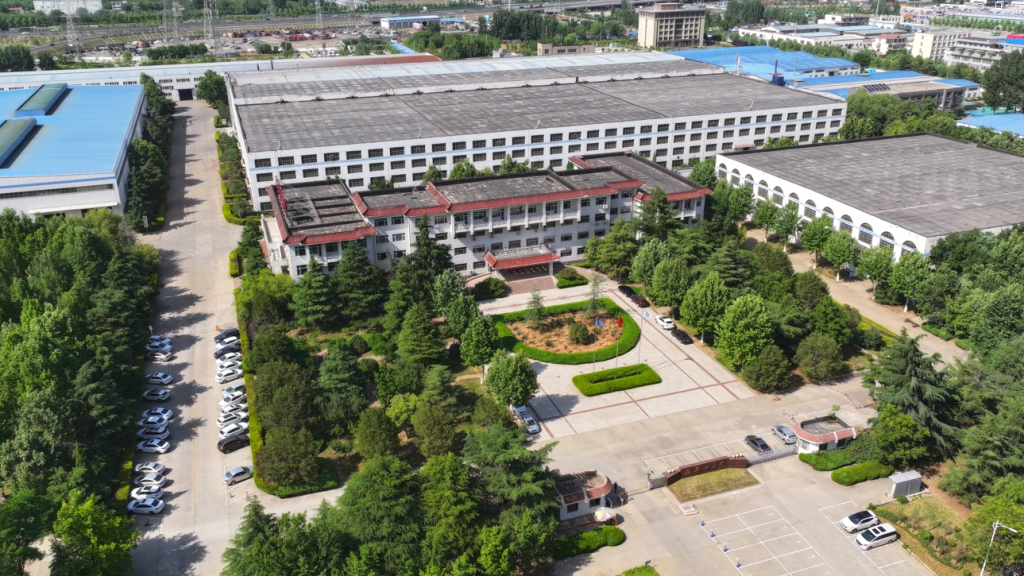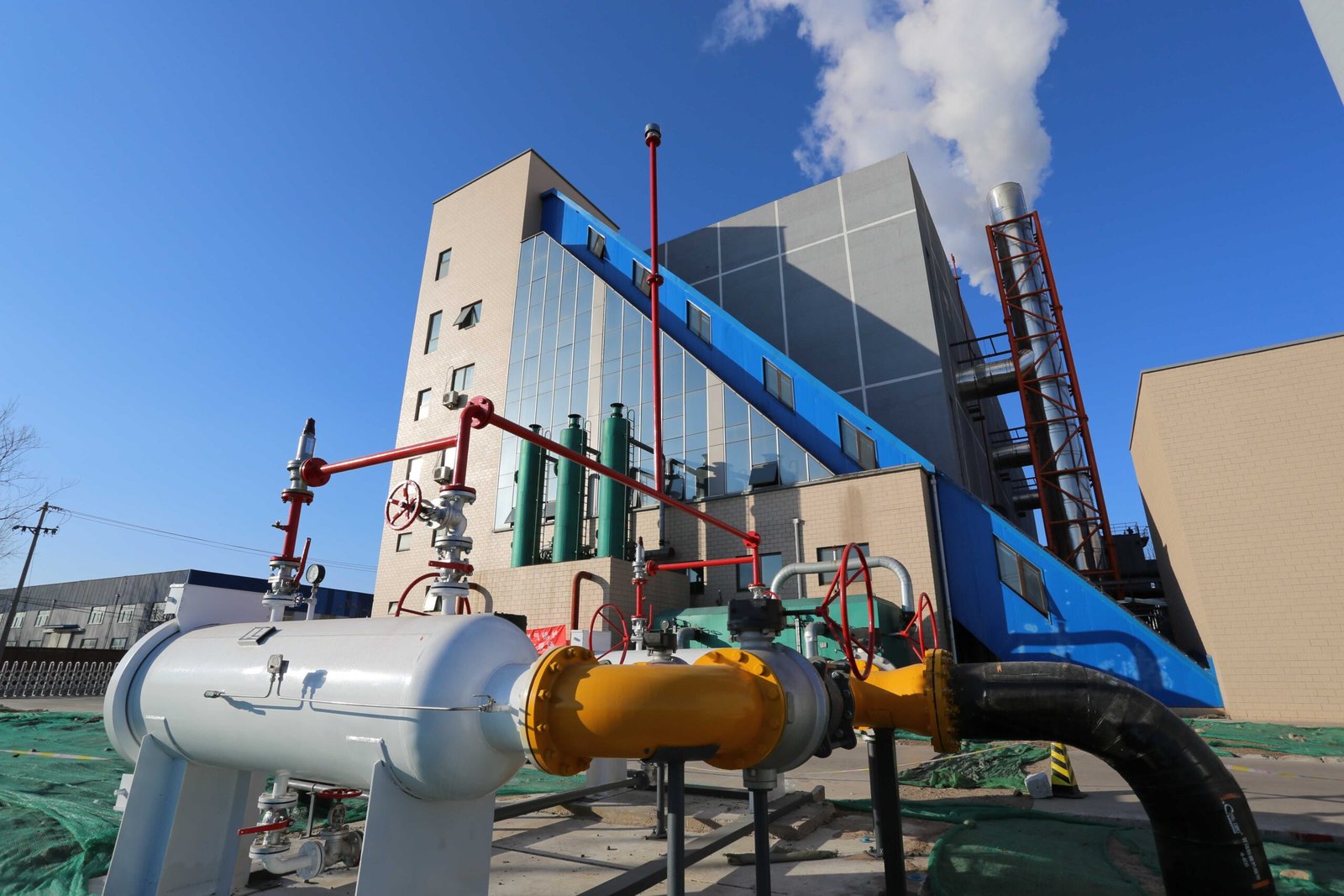
A boiler that starts up wrong rarely gets a second chance to make it right. Misaligned burner geometry, undertightened flange joints left that way because the site team was rushing to meet a handover date, a feedwater system that wasn’t properly flushed before first fire — these aren’t hypothetical risks. They translate directly into refractory damage in the first week, flame instability that trips the safety interlock every few hours, or, worst case, a pressure-part failure that puts the unit out of service for months and exposes the owner to insurance and regulatory consequences that dwarf the original installation budget. For an oil- or gas-fired industrial boiler, the installation and commissioning phase is where the entire lifecycle cost gets set.
A properly installed and commissioned oil or gas fired industrial boiler — covering foundation preparation, burner alignment, piping connections, controls calibration, and a minimum 72-hour full-load acceptance run — typically takes 7 to 21 days on site depending on unit capacity and site readiness, and when done correctly to ASME PTC 4 or EN 12952 standards, delivers thermal efficiencies of 88–95% (LHV basis) with NOx emissions controllable below 30 mg/Nm³ using ultra-low NOx burners and flue gas recirculation.
What most installation guides won’t tell you is how much the sequence matters — not just the checklist, but the logic behind why certain steps have to happen before others, and what actually goes wrong on real plant floors when they don’t. The difference between a boiler that runs reliably for 20 years and one that becomes a maintenance headache inside the first operating season usually traces back to decisions made during those first three weeks on site.
Site Survey, Foundation Design, and Pre-Installation Civil Requirements
Get the civil work wrong and you will be paying for it long after the boiler is running — or not running, as the case may be. Rework on a poured concrete foundation after the boiler has arrived on-site is expensive, slow, and occasionally project-killing. Everything described below should be resolved before the equipment leaves the factory.
Site Survey Checklist
Start with clear height. The boiler room structural ceiling or roof beam must clear the highest point of the boiler — drum top, steam outlet header, or stack stub, whichever is tallest — by at least 1 m. In practice, for a fire-tube shell boiler in the 10–20 t/h range, that usually means a finished floor-to-beam clearance somewhere between 5 m and 7 m, depending on whether you have an integral economizer stacked on top. Don’t estimate this from a 2D drawing; measure the actual delivered envelope dimensions from the manufacturer’s certified general arrangement, not the catalog sheet.
Floor load-bearing capacity matters more than most civil engineers expect. Shell boilers up to roughly 20 t/h impose static floor loads typically in the 15–25 kN/m² range — the exact figure depends on boiler water-filled weight, whether the burner front-end assembly is cantilevered, and how the load distributes through the skid or saddle feet. Get the manufacturer’s certified loading diagram, not a generic estimate. Access aisles between the boiler casing and any wall, platform, or adjacent equipment should be at least 1.5 m clear — enough for a technician carrying a burner nozzle assembly or a length of tube. Tight rooms always cause maintenance problems eventually.
Natural ventilation openings are calculated against rated thermal input. A rough working rule for oil- and gas-fired rooms is roughly 250–300 cm² of free opening area per 100 kW of burner rating, but verify against the applicable national code (EN 746, GB 50041, or whichever governs your jurisdiction) because combustion air demand and explosion-risk dilution requirements can push that number higher, particularly for natural-gas rooms below grade.
Foundation Sizing and Grouting Tolerances
Concrete grade for boiler foundations is generally C25 or C30 minimum — C20 is not adequate for anchor bolt pull-out loads under a forced-draft fan. The anchor bolt pattern must match the certified base plate drawing exactly; field-drilled corrections into cured concrete are a known source of long-term cracking. For forced-draft and induced-draft fan pedestals, vibration isolation is not optional: anti-vibration mounts rated to the fan’s unbalanced force at running speed, with inertia block mass typically 1.5–3× the fan assembly weight depending on fan speed and soil stiffness. Grouting clearance under the base frame should be held to ±2 mm levelness across the full baseplate length before final grouting; anything looser than that and you will fight burner alignment and flue connection stress for the life of the unit.
Fuel Supply Infrastructure
For natural gas systems, the pressure regulation and metering skid should sit outside the boiler room or in a dedicated ventilated enclosure — not tucked against the boiler wall where maintenance access is constrained. Minimum distance from any ignition source is governed by local gas safety codes, but 3–5 m of clear separation is typical. The gas meter room needs continuous mechanical or natural ventilation: cross-ventilation with openings at both high and low levels.
Heavy fuel oil (HFO) or diesel day-tanks should be positioned to give gravity or pump-assisted flow to the burner return circuit, with secondary containment bunding sized for at least 110% of the largest tank volume — that figure is standard in EU ATEX/environmental guidance and similar requirements appear in most national environmental codes. Oil supply pipework bend radii for HFO should be generous; sharp elbows in heated heavy-oil lines cause localized coking and are a persistent maintenance headache. For light oil (gas oil, diesel), minimum bend radius follows standard piping practice, but trace heating continuity at pipe supports is worth checking before winter startup.
Secondary containment bunding for fuel oil day-tanks is required to hold at least 110% of the largest single tank volume under EU environmental regulations.True
This requirement appears in the EU's Environmental Permitting regulations and is consistent with CIRIA C736 guidance on secondary containment design; it is widely adopted as a baseline in non-EU jurisdictions as well.
Utility Connections Pre-Work
Feedwater treatment plant outlet should be confirmed for both pressure and flow rate before the boiler room pipework is designed — don’t assume the softener or RO skid outlet matches the boiler feed pump suction requirements without checking. Blowdown pits need to be sized for the intermittent blowdown volume plus cooling dilution water; undersized pits overflow, which is both an environmental violation and a slip hazard.
Chemical dosing station footprint is modest — typically 1.5 m × 2 m for a dual-pump skid — but it needs a drain connection to a neutralization pit, not the storm drain. Instrument air supply to the control panel and actuated valves should be 0.5–0.7 MPa, dried and filtered; a dew point of −20 °C or better at line pressure is a reasonable specification. Wet instrument air causes diaphragm actuator failures and positioner corrosion that will annoy you forever. MCC room location should keep power cable runs to the boiler under roughly 50 m where possible; longer runs at the motor voltages involved (typically 380–415 V or 6 kV for large FD fans) require cable sizing review and can push voltage-drop into a range that affects soft-starter or VFD performance.
Permitting and Regulatory Coordination for Overseas Projects
Timelines vary widely by country and should never be assumed. Building permit, pressure vessel registration, and environmental impact assessment submissions in Southeast Asia, the Middle East, or Africa typically take anywhere from 6 weeks to 6 months depending on local authority workload and whether the documentation package — including boiler manufacturer certification, third-party inspection reports, and local-language translations — is complete at first submission. An incomplete submittal can easily add 8–12 weeks. Taishan Group’s EPC team routinely prepares the full documentation package in parallel with manufacturing, which compresses the overall project schedule rather than letting permitting become the critical path item. For pressure vessel registration specifically, most jurisdictions accept ASME Section I, EN 12952/12953, or equivalent certification from a recognized notified body; confirming which certificate the local authority accepts before manufacturing is complete avoids costly re-inspection.
Boiler Unloading, Rigging, and Positioning: Step-by-Step Field Procedures
Getting a large fire-tube or water-tube boiler from the flatbed to its foundation without incident is one of those jobs that looks straightforward until something goes wrong — and when it goes wrong, it tends to go expensively wrong. A dropped pressure vessel, a cracked saddle, a drum that’s 3 mm out of level: each of those creates a cascade of rework that pushes commissioning back by weeks. The sequence below is how experienced field crews approach it.
Pre-Delivery Inspection Before You Sign Anything
When the truck arrives, resist the urge to start unloading immediately. The first 30–45 minutes on site are documentation time, and they matter enormously.
Check the shipping marks against the packing list and contract drawings. Verify that all transport saddles are intact and haven’t shifted — saddle displacement is common on long-haul road freight, especially over rough roads, and it can indent the shell if the boiler rocked during transit. Inspect all manholes and handhole covers: they should be sealed tight. More critically, confirm that the nitrogen blanket pressure is still within the 0.03–0.05 MPa range specified by the manufacturer. A pressure gauge or valve port is usually provided on the shell for this check. If the nitrogen has bled off completely, moisture may have entered the steam and water-side surfaces, which means you’re looking at potential rust before the unit ever fires. Document it, photograph it, and raise it with the freight forwarder before signing any delivery or customs release documents. Signing first and complaining later rarely ends well.
A nitrogen blanket of 0.03–0.05 MPa maintained during boiler shipping effectively prevents internal corrosion of pressure surfaces during transit.True
Positive nitrogen pressure displaces oxygen and moisture from internal pressure-part surfaces, preventing oxidation corrosion during transport and storage. This is standard practice per boiler manufacturer protocols and is consistent with NACE and industry storage guidelines.
Crane Lift Planning
Never assume the manufacturer’s stated dry weight is your lift weight. By the time you add insulation (often factory-applied), the burner if pre-mounted, any refractory lining in the furnace, and residual water or oil from hydrostatic testing, gross lift weight can run 10–20% heavier than the nameplate figure, depending on boiler size and configuration. Size your crane with a minimum 1.25 safety factor on that gross weight — some EPC specifications require 1.5 for vessels above 30 tonnes.
Use only the manufacturer-designated lift lugs. Improvised rigging through nozzle flanges or shell fittings has caused catastrophic drops and is non-negotiable from an insurance standpoint. Confirm sling angles: spreader beams are usually necessary for units over roughly 8–10 metres long to keep sling angles above 60° and avoid crushing loads on the shell.
Ground bearing pressure under outrigger pads deserves a separate check. A 100-tonne crane working at near-full radius can impose point loads of 40–60 tonnes per pad, give or take depending on boom angle. If your site soil or concrete apron hasn’t been designed for that, you’ll sink an outrigger pad mid-lift — which is exactly as alarming as it sounds.
Skidding and Jacking to Final Position
Once the boiler is set roughly over the foundation, precision jacking begins. Use hydraulic leveling jacks rather than wedges; wedges slip. A rotating laser level referenced to the boiler drum centerline is the practical tool here — you’re targeting drum levelness within 1 mm/m longitudinally and 0.5 mm/m transversely. Those tolerances exist because a drum that’s out of level affects water circulation, gauge glass readings, and in extreme cases, safety valve inlet conditions.
With levelness confirmed, torque anchor bolts to the manufacturer’s specified values (always torque in a cross pattern, not sequentially around the perimeter). Then pour non-shrink cementitious grout under the base frame while the boiler is still held by jacks, working from one side to avoid air pockets. Allow full cure — typically 24–48 hours depending on grout brand and ambient temperature — before releasing jacks. Pulling jacks too early is a common shortcut that causes the frame to settle unevenly during initial thermal expansion.
Clearance Verification After Setting
Before any pipework or wiring begins, walk the clearances systematically. On fire-tube designs, confirm that the tube bundle withdrawal space shown on the general arrangement drawing is actually clear — it’s surprisingly common for a wall or structural column to end up closer than planned once you’re on the real floor. Burner swing-out radius needs to be clear of adjacent equipment, access ladders, and electrical conduit routes. Safety valve discharge piping must route to open atmosphere or a proper vent header without any pocket where condensate could accumulate and create hydraulic back-pressure on the valve disk. The MAWP nameplate and stamping should face an accessible direction for the inspection authority’s witness points.
Staging Auxiliary Equipment
Auxiliary skids — economizer, air preheater, blowdown vessel, deaerator, chemical dosing skid, BMS panel — should not all arrive on day one unless you have the laydown space to handle them without cluttering the boiler room. Sequence deliveries to match the installation schedule. In practice, the BMS panel and chemical dosing skid can arrive late in the sequence; they’re small and easy to maneuver. The deaerator and blowdown vessel, by contrast, need early positioning because piping to them intersects with other primary connections. An economizer sitting in the wrong corner of a boiler room for three weeks while crews work around it is a friction point and a safety hazard both.
Burner, Fuel Train, and Combustion Air System Installation
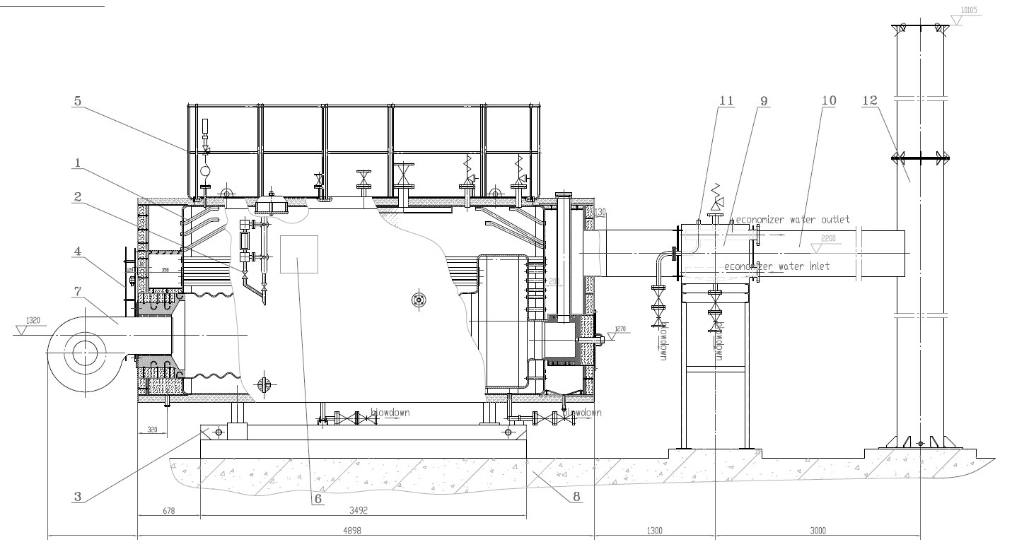
The burner assembly and fuel supply system cause more first-fire failures and post-commissioning nuisance trips than any other subsystem on an oil- or gas-fired boiler. Get the civil work right, set the boiler on its foundation correctly — and then rush the fuel train, and you’ll spend your first week chasing gas leaks, flame-failure faults, and puzzled looks from the local authority having jurisdiction. This section covers what actually matters, in the order it matters.
Burner Mounting and Alignment
Most industrial burners in the 5–50 MW range arrive as a flanged mono-bloc assembly — burner head, fan, and control panel in one unit. The mating flange on the boiler front plate must be clean and flat; any weld spatter or paint proud of the face will cause a flue-gas bypass path around the quarl tile. Torque the mounting bolts in a cross-pattern sequence, not circular, to the manufacturer’s specified value — typically 60–120 N·m depending on flange diameter and bolt size. If the manual just says “tight,” that’s not acceptable; measure it.
The refractory quarl tile fit-up deserves more attention than it usually gets. The tile must seat fully into the furnace opening with no gap larger than roughly 2–3 mm around the circumference; pack any gap with refractory ceramic fiber, not fireclay mortar. A loose quarl tile will erode within weeks under thermal cycling.
Flame scanner sight tube angle is typically set between 0° and 15° off the burner axis — close enough to see the root of the flame, far enough that the lens doesn’t coke up in the first hour. For UV scanners, route the signal cable away from ignition transformer leads and any high-voltage wiring; induced interference is a common cause of phantom flame-failure trips that are genuinely hard to diagnose after the fact. Ionization sensors need a direct earth-bonded cable run — don’t share a conduit with power cables.
Gas Fuel Train Assembly
The gas train must follow EN 746-2 or NFPA 85 double-block-and-bleed configuration: two solenoid shutoff valves in series with a vent valve between them, wired so the vent opens whenever both main valves close. This is not optional, and in my experience it’s the item most likely to be “value-engineered” out on low-bid projects.
Work upstream to downstream: inlet filter (50–100 µm for natural gas, 100–200 µm for LPG), manual isolating ball valve, pressure regulator, low-gas-pressure switch, high-gas-pressure switch, then the double-block-and-bleed solenoid train. Set the low-pressure switch at roughly 60–70% of minimum firing pressure; set the high-pressure switch at about 120% of maximum rated inlet pressure. These are starting points — adjust during commissioning based on actual supply fluctuation at the site.
Every threaded joint in the gas train gets torqued to spec and leak-tested with nitrogen at 1.5× MAWP before any gas is introduced. Use snoop solution or an electronic leak detector on every joint, not just a soap-and-water wipe. Document each test with the nitrogen supply pressure and hold time (minimum 10 minutes at test pressure with zero detectable drop).
Double-block-and-bleed valve configuration is mandatory for gas burner trains under NFPA 85 and EN 746-2True
Both standards explicitly require two independently actuated shutoff valves in series with an intermediate vent valve to safely isolate the burner from the gas supply on shutdown or trip.
Heavy Fuel Oil System
No. 6 HFO (residual fuel) needs to arrive at the burner gun between roughly 50°C and 80°C to flow and atomize properly — the exact set-point depends on the specific viscosity grade, which varies meaningfully between suppliers. Electric trace heating on the supply and return lines is standard; steam tracing works too but adds a condensate management headache. Insulate everything, including the flanged joints, because a bare flange on a trace-heated line loses enough heat to cause a cold plug in a cold climate within minutes of a pump stop.
Size the duplex strainer for 150–250 µm elements on the suction side of the oil pump. The duplex configuration matters because you need to switch sides without a unit trip during a long campaign. Set the oil pressure control valve to maintain steady atomizing pressure — typically in the 2–4 bar range at the burner gun, but check the specific burner datasheet. The recirculation return line must go back to the day tank, not the main storage tank, to avoid continuously heating your entire fuel inventory.
Forced-Draft Fan Installation
Shaft alignment between the FD fan and its drive motor should be within 0.05 mm TIR (total indicator reading) for flexible-coupled units. Anything looser and you’ll see elevated bearing temperatures within the first 500 hours. Use a flexible duct connection — canvas or silicone-coated fiberglass — between the fan outlet and the combustion air duct to break vibration transmission to the boiler casing and instrumentation.
The inlet air volume damper actuator needs to be calibrated to the burner management system before first light-off: confirm that 0% signal corresponds to a physically closed damper (not just the actuator at minimum travel), and that the damper opens smoothly without binding throughout its range. Fit a differential pressure gauge across the inlet air filter with a marked alarm line — filter fouling is invisible otherwise, and a partially blocked inlet filter on a large burner costs measurable fuel consumption.
Combustion Air Pre-Heating
If the boiler is fitted with a tubular or rotary regenerative air preheater, the bypass damper sequencing at startup is critical. During cold start, keep the bypass open and route flue gas around the preheater until the cold-end temperature of the air preheater tubes climbs above 130°C — for sulfur-containing fuels, this threshold is the practical acid dewpoint margin. Running cold flue gas through the preheater too early causes sulfuric acid condensation on the tube surfaces, and the resulting corrosion on carbon steel elements can perforate tubes within a single season.
Soot blower connections on tubular air preheaters need to be on the flue-gas side, timed to run during steady operation rather than during startup or shutdown when temperatures are marginal. Wire the soot blower permissive into the BMS so it cannot activate below minimum load.
Boiler Auxiliary Systems Installation: Feedwater, Blowdown, Chemical Dosing, and Flue Gas
Get this section of the installation wrong and you will fail hydraulic testing, trip on low-water interlocks during first firing, or — worst case — commission a boiler that starts scaling internally within weeks. These systems are not glamorous, but they define whether the pressure boundary is complete and whether the boiler survives its first year of operation.
Feedwater System Piping and Pump Arrangement
The feed pump header should be sized to deliver at least 120% of rated evaporation flow — not the nameplate flow, the actual maximum continuous rating you expect to operate at. Why 120%? Because the feedwater regulating valve needs headroom to modulate without hunting, and you need margin for a stuck-open blowdown valve scenario. Pump discharge pipe velocity should stay in the 1.5–2.5 m/s range; push it higher and you start eroding fittings at the bends near the economizer inlet.
Always install duty and standby pumps with individual discharge non-return valves and isolating gate valves in the sequence: pump outlet → non-return valve → isolating valve → common header. The non-return valve goes closest to the pump. This is not optional — it prevents backflow through a stopped pump from pressurizing its mechanical seal. Skipping the individual isolating valve is a maintenance headache you will regret on the first pump swap.
At the economizer inlet, the feedwater regulating valve actuator should be oriented so it fails open on loss of signal — confirmed with the control vendor before wiring. A fail-closed FWV on a fire-tube boiler means the drum drains during a power interruption. Low-water level alarm wiring must be independently routed from the low-low cutout interlock; combining them on a single switch is a common shortcut that defeats the two-stage warning logic required by most insurance underwriters and by EN 12953-7.
Deaerator Installation
Atmospheric deaerators need their steam supply pressure reducing valve set between roughly 0.02 and 0.05 MPa gauge. Set it too high and the vent plume becomes excessive and you lose condensate heat. Set it too low on a cold morning startup and dissolved oxygen climbs above the 7 µg/L target before the operator realizes anything is wrong. Vent lines must run to atmosphere — unobstructed, no rain cap with a flap that sticks. Overflow lines should discharge to the blowdown vessel or a drain with a visible flow indicator; routing to a closed drain without visual confirmation means a stuck level valve can quietly dump your feedwater for hours.
Dissolved oxygen verification during commissioning typically uses a calibrated inline DO probe with a grab-sample comparison. Do not accept the factory calibration certificate as final — verify with a Winkler titration on a live sample after the deaerator reaches steady-state temperature at roughly 104–105 °C.
Blowdown System
Bottom blowdown valve sequencing matters more than most installation crews appreciate. The standard timed sequence — open the second (downstream) valve first, then crack the first valve, hold for 3–5 seconds, close both — is designed to keep the higher-quality seat of the first valve from seeing erosive flash. Reversing the sequence erodes the upstream seat within months.
The blowdown vessel must be rated for worst-case flash steam, which means calculating the flash fraction at your drum operating pressure discharging to atmospheric. At 1.0 MPa drum pressure, flash fraction runs around 12–14% by mass; the vessel shell and vent line need to handle that transient vapor load without lifting a relief valve on every blowdown cycle. A plate heat exchanger on the blowdown drain to preheat makeup water is worth evaluating if continuous blowdown exceeds roughly 3% of evaporation — payback can be under two years depending on fuel cost and water temperature differential.
Continuous surface blowdown TDS probe positioning is frequently wrong in the field. The probe tip should sit 50–75 mm below the waterline at normal operating level, not at the bottom of the tapping. Position it too low and suspended solids skew the reading high; too high and it reads air during swell.
Chemical Dosing
Phosphate dosing for scale control should inject downstream of the deaerator outlet, not into the feed pump suction. Injecting upstream of the deaerator removes oxygen scavenger effectiveness by diluting the contact zone. Sodium sulfite remains the most common oxygen scavenger for boilers below about 4 MPa; DEHA is preferable at higher pressures where sulfite decomposition produces SO₂ and contributes to corrosion in superheaters.
Phosphate and oxygen scavenger dosing should inject at separate points, not through a combined tee upstream of the feed pump.True
Mixing phosphate and sodium sulfite before the pump can cause precipitation in the pump casing and distort both chemical reactions; ABMA BG-02 and most boiler water treatment guidelines specify separate injection points.
Condensate return conductivity monitoring catches contamination events — a heat exchanger tube leak, process ingress — before they damage the boiler drum internals. Mount the conductivity sensor in the condensate return header before it mixes with makeup, not after. Chemical storage requires mechanical ventilation (minimum 10 air changes per hour in practice) and a dedicated bunded sump sized for the largest single chemical container on site.
Flue Gas System and Stack
Stack sizing for natural draft is often treated as a formality, but getting it wrong costs real money. At full load, the stack must generate at minimum 3 Pa negative pressure at the economizer outlet — more for larger units or installations with complex duct routing. Stack diameter depends on flue gas volume, temperature, and velocity; keeping velocity in the 5–10 m/s range at rated load gives reasonable draft without excessive heat loss.
Expansion joints between the economizer outlet and the stack base are non-negotiable. Omit them and thermal cycling will crack the economizer casing welds within one to two heating seasons. Use stainless-lined fabric expansion joints rated for the flue gas temperature at that point — typically 160–220 °C depending on economizer outlet design and fuel sulfur content.
CEMS probe locations require careful thought. The O₂ and NOx probes should sit at a straight duct run of at least 5–8 duct diameters downstream of any bend, and 2–3 diameters upstream of any disturbance. Installing them immediately after a 90-degree turn gives stratified readings that will fail regulatory calibration checks. SO₂ monitoring is only meaningful if you are running distillate or residual oil fuels — on natural gas it is largely irrelevant, though some jurisdictions require it regardless.
Hydraulic Pressure Testing, Refractory Dry-Out, and Pre-Commissioning Inspection
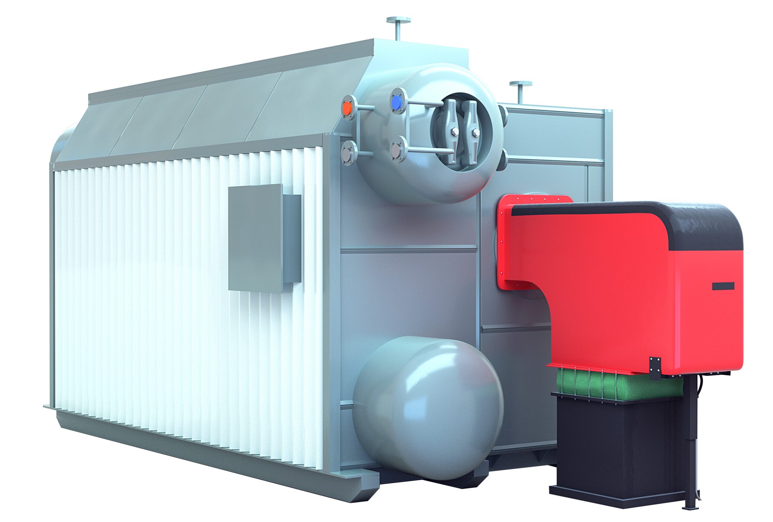
This is the stage where a properly installed boiler gets proven — or where shortcuts from earlier phases come back with consequences. Every leak path, every missed vent, every under-cured castable refractory shows up here, before flame is ever introduced. Rushing through it is the single most reliable way to generate a first-fire failure.
Hydraulic Pressure Test Procedure
Fill the system with treated water. Chloride content must stay below 50 ppm — austenitic stainless components in superheater circuits are particularly sensitive to chloride-induced stress corrosion cracking, and this is not a theoretical risk. Cold, clean condensate or softened/demineralized water is standard. Connect a calibrated test gauge traceable to a national metrology standard; a borrowed Bourdon gauge from the instrument shelf is not acceptable for a witnessed test.
Vent air completely from all high points before you begin pressurizing. Air pockets compress; water doesn’t. Trapped air will give false pressure readings and can cause a violent pressure drop when it migrates, masking real leaks.
Raise pressure at no more than 0.3 MPa/min. For a boiler with a maximum allowable working pressure (MAWP) of, say, 1.25 MPa, you’re holding at 1.56 MPa — that’s the 1.25× hydrostatic test pressure required under ASME Section I and EN 12952-8. Hold that test pressure for a minimum of 30 minutes while you walk every weld seam, tube-to-header joint, flange face, and threaded fitting. Then bleed down to MAWP and do it again. Some defects only become visible at the lower, sustained pressure because elastic deformation relaxes.
Hydraulic pressure test must be performed at 1.25× MAWP and held for at least 30 minutes per ASME Section I requirements before any boiler is fired.True
ASME Boiler and Pressure Vessel Code Section I, PG-99 specifies hydrostatic test pressure at 1.5× MAWP for new construction, though some EN 12952-8 and local jurisdictions accept 1.25×. The 30-minute hold and MAWP re-inspection step is consistent with both standards. Always verify with the applicable code edition and the local authority having jurisdiction.
Leak Identification and Repair
Mark every weeping joint with chalk — not tape, not marker — immediately when found. Chalk washes clean for re-inspection; it doesn’t hide the surface. Depressurize fully before touching anything. Tightening a threaded connection or a gasketed flange under residual pressure can cause sudden release and injury; it also rarely seals the leak properly because the joint is still stressed in the wrong direction.
After any repair — weld, re-torque, or fitting replacement — you re-test from the beginning. No shortcuts. One repair cycle that misses a second leak two joints away will cost you another full cycle anyway.
Refractory Dry-Out Firing Curve
Castable and plastic refractory cannot be brought to operating temperature cold. Free moisture and chemically bound water must be driven out in controlled stages or the material will crack, spall, and eventually fall into the combustion chamber — which means burner damage, hot spots on pressure parts, and a refractory re-line job inside a new boiler.
A typical dry-out sequence runs roughly as follows:
| Phase | Temperature Range | Ramp Rate | Hold Time | Purpose |
|---|---|---|---|---|
| 1 | Ambient → 120°C | ~25°C/h | 8 hours | Drive off free moisture |
| 2 | 120°C → 300°C | ~20°C/h | 8 hours | Remove chemically bound water |
| 3 | 300°C → 600°C | ~30°C/h | 4–6 hours | Sinter dense castable |
Total elapsed time runs 48–72 hours depending on refractory mass and ambient humidity — longer in tropical climates where the castable absorbs moisture during installation delays. Use the burner on low-fire only throughout this sequence. A thermocouple embedded in the refractory at its thickest section is the controlling measurement, not the furnace gas temperature.
Pre-Commissioning Checklist and BMS Dry-Run
Before any live flame, walk through the following systematically. Valve position verification: every normally-open safety and feedwater isolation valve confirmed open, every normally-closed drain and blowdown valve confirmed shut, tagged and signed off. Instrumentation loop checks should confirm a live 4–20 mA signal from each pressure, temperature, and level transmitter to the DCS or burner management system (BMS) panel — not just continuity, but calibrated span. A drum level transmitter that reads 50% at the wrong physical level will cause low-water cutoff to mis-trip, or worse, to not trip when it should.
Safety valve lift testing at set pressure is non-negotiable and must be witnessed. Water level gauge calibration against the drum centerline datum catches installation errors that are surprisingly common when gauge glasses are installed by crews unfamiliar with the specific drum geometry.
Run the BMS logic sequence with simulated inputs and no flame present. Confirm that every interlock — high gas pressure, low combustion air flow, flame failure — drives the correct shutdown response at the panel. On projects where the BMS was supplied separately from the burner OEM, integration bugs show up almost exclusively at this step.
Third-Party Inspection and Certification
The hydraulic test and safety valve lift test should be witnessed by the classification society representative or the local pressure vessel authority — whoever holds jurisdiction. That witness inspection is what generates the boiler registration certificate. Without it, the plant owner cannot legally operate the boiler in most jurisdictions, and no insurance policy will respond to an incident on an unregistered vessel.
Assemble the complete documentation package before handover: hydrostatic test records with gauge calibration certificates, as-built drawings, material mill certificates, weld inspection reports, BMS sequence logic printout, and the refractory dry-out temperature log. Plants that skip the documentation package tend to spend 3–5× more time on their first regulatory inspection than those that keep clean records from the start.
First Firing, Steam Raising, and Boiler Chemical Cleaning Procedures
Getting to first fire feels like a milestone, but it’s actually where the risk profile shifts rather than decreases. A pressure vessel that passed hydro test and refractory dry-out is still full of mill scale, fabrication oils, weld flux residues, and whatever debris found its way in during installation. Rush through boil-out or skip steam blowing on a superheated unit, and you’ll pay for it later in fouled steam traps, eroded turbine nozzles, or accelerated waterside corrosion. The sequence below is not optional.
First Ignition Under BMS Control
Before a single spark fires, the burner management system must complete its pre-purge cycle. Per NFPA 85, that means verified airflow at a minimum of 25% of maximum rated airflow for at least 30 seconds — enough volume to displace any unburned fuel that may have accumulated in the firebox. Do not defeat this interlock. In practice, some commissioning crews get impatient with the purge timer when they’re under schedule pressure, but a firebox explosion during first light-off is a project-ending event, not a delay.
After purge, the BMS initiates pilot ignition. Confirm the pilot flame signal is above the BMS-defined threshold (typically 1.5–2.5 VDC for UV scanners, but check the specific relay card documentation) before proceeding to main burner light-off. Main burner ignition happens at minimum firing rate — usually 20–30% of rated thermal input — and the flame signal must stabilize and hold above threshold before any load step is attempted. If the BMS trips on flame failure at this stage, stop, identify root cause, and do not simply reset and retry more than twice without investigating. Repeated ignition attempts pump unburned fuel into a hot firebox.
Controlled Pressure Rise to Working Pressure
Initial steam raising is slow by design. Limit pressure rise to roughly 0.1 MPa per 10 minutes. On a 1.6 MPa saturated steam boiler, that means at least 2.5 hours from cold to working pressure — more if the drum is large. The reason is thermal stress: the differential temperature between the top and bottom of the steam drum must stay below about 40°C. Top-of-drum metal heats faster because steam rises; if you fire too hard, early, you can induce differential expansion that damages drum internals or nozzle welds.
Keep the drum air vent cracked open until you see a steady steam flow escaping — this confirms the steam space is free of air, which would otherwise create a non-condensable gas pocket that skews pressure readings and can accelerate oxygen corrosion. Only then close the vent and begin pressure buildup in earnest.
Alkaline Boil-Out Procedure
This is the step most installation teams under-resource. Fill the boiler to normal water level with a solution of tri-sodium phosphate at 3–5 kg per cubic meter of boiler water volume, plus sodium hydroxide at 1–2 kg/m³. Fire to approximately 75% of working pressure — not full pressure, because you want to be able to open blowdown valves safely — and hold that condition for 24 to 48 hours. The duration depends on how contaminated the waterside surfaces are; a unit that sat on-site for several months in a humid climate typically needs the longer end of that range.
Blow down the bottom blowdown valve every 4 hours to remove loosened scale and saponified oils. You will see discolored, oily discharge in the early blowdowns — that is exactly what you want out of the system. After the boil-out cycle, drain completely, flush with clean water, and refill with fresh chemically treated feedwater. Do not skip the flush; residual caustic left in low-flow zones will continue attacking the metal.
Alkaline boil-out using trisodium phosphate and sodium hydroxide effectively removes fabrication oils and mill scale from new boiler waterside surfaces.True
This is standard pre-commissioning practice documented in ASME guidelines and EN 12952-7. The alkaline solution saponifies oils and loosens mill scale, which is then removed via bottom blowdown. Skipping this step leads to localized overheating under scale deposits and accelerated pitting corrosion.
Steam Blowing of Superheater and Main Steam Lines
On units with superheaters or long steam distribution headers, steam blowing is non-negotiable before connecting to any process load. The goal is to dislodge weld slag, pipe scale, and construction debris with high-velocity steam before any of it reaches control valves, turbines, or heat exchangers.
Operate at roughly 70–80% of rated pressure but configure the temporary blowdown piping so the velocity through the main steam line meets or exceeds rated operating velocity — the cleanliness factor (ratio of blowing momentum to operating momentum) must exceed 1.0. Weld a mild steel impact plate into the temporary exhaust piping and inspect it after each blow sequence. Replace the plate and repeat until two consecutive plates show no pitting or embedded particles. Record every blow: date, pressure, duration, plate condition. That record becomes part of the commissioning dossier.
Post-Boil-Out Water Chemistry Verification
Before declaring the boiler ready for performance testing, the water chemistry must confirm what the physical procedures started. Target values: pH 10.5–12.0 (phosphate treatment program), phosphate residual 10–30 mg/L, dissolved iron below 0.3 mg/L, and zero visible oil sheen on a sample drawn into a clean glass jar. Iron above 0.3 mg/L usually means the boil-out was too short or the flush inadequate — repeat the flush and retest rather than proceeding. An oil sheen means residual contamination is still present; the boil-out cycle needs to be extended.
Only when water chemistry is within spec, the steam blowing acceptance criterion is met, and the BMS has logged a clean first-fire sequence without nuisance trips should the unit move into the 72-hour full-load acceptance test phase.

Combustion Tuning, Performance Testing, and Efficiency Optimization at Full Load
This is the stage where installation work gets validated against the numbers the project was sold on. Get it wrong and you hand the client a boiler that runs legally but inefficiently — or one that trips on NOx limits six months later when the local authority does a stack test.
Combustion Analyzer Measurements Across the Firing Range
Don’t run combustion tests only at 100% MCR. In practice, most process boilers spend a significant portion of their operating life at part load — 60–80% is common in plants with variable steam demand or shift-based production. Test at a minimum of four points: 30%, 60%, 80%, and 100% MCR, letting the boiler stabilize for at least 15 minutes at each firing rate before logging data.
Target flue gas O₂ on a dry volume basis: 2.5–3.5% for natural gas, 3.0–4.0% for fuel oil. CO should stay below 100 ppm at every tested rate. Stack temperature versus the design prediction should fall within ±5°C — deviations beyond that usually point to fouled heat transfer surface, incorrect gas-side baffling, or an air ingress problem you missed during the pre-commissioning inspection. If stack temperature runs high at low firing rates but corrects at full load, suspect recirculation duct leakage rather than a surface cleanliness issue.
Air-to-Fuel Ratio Setting and BMS Trim Control
Excess air management is where efficiency and emissions intersect. Too lean and you get incomplete combustion — CO spikes and possible carbon deposition on the refractory. Too rich and dry flue gas losses climb steeply. For a packaged fire-tube boiler on natural gas, excess air of roughly 5–12% at full load is achievable with a good forced-draft burner. For fuel oil, you’re typically looking at 10–18% depending on atomization quality and fuel viscosity; heavy oil at the wrong temperature will push that higher.
At each test point, physically record the burner air register position, damper angle or VFD speed (whichever applies), and calculated excess air percentage. If the BMS includes a continuous O₂ trim controller — increasingly standard on units above roughly 10 t/h — verify the trim set-point at each firing rate and confirm the control response doesn’t hunt. Set the low O₂ alarm no lower than 1.5% dry to maintain a safety margin against CO breakthrough at turndown. Document every set-point. A commissioning record with blank set-point fields is a handover risk.
Thermal Efficiency by the Indirect (Heat Loss) Method
The indirect heat loss method per ASME PTC 4 is more accurate than direct input-output measurement for industrial boiler acceptance testing because it is less sensitive to fuel flow meter errors.True
Direct efficiency measurement requires precise fuel mass flow, which is difficult to achieve within ±0.5% at site conditions. The indirect method sums individually measured losses — each of which is small and measurable — making it preferred by ASME PTC 4 and common in contractual acceptance tests.
Quantify each loss component: dry flue gas loss (typically the largest, 4–7%), hydrogen combustion loss (about 10.8% of hydrogen content in fuel, fixed by fuel chemistry), moisture-in-fuel loss, radiation and convection losses from the boiler casing (usually 0.3–0.8% depending on insulation quality and unit size), and blowdown loss (depends on blowdown rate, often 0.2–1.0%). Sum the losses, subtract from 100%, and compare against the guaranteed efficiency — typically 90–93% LHV for gas-fired units, 88–91% for fuel oil, depending on capacity and exhaust stack temperature design point.
If measured efficiency falls more than 1.5 percentage points below the guarantee, don’t accept it as instrument scatter. Investigate surface cleanliness, air ingress, and fuel specification before signing off.
NOx and Emissions Compliance Verification
Sample at the CEMS probe location specified in the environmental permit, not just anywhere convenient on the stack. Correct measured NOx to the reference O₂ concentration — 3% for gas, 6% for oil, per EU IED convention — before comparing against the emission limit. A reading that looks compliant at actual O₂ of 9% can exceed the limit once corrected.
Standard low-NOx burners on gas-fired units typically achieve 60–80 mg/Nm³ after tuning. Ultra-low NOx burners with flue gas recirculation can reach below 30 mg/Nm³, but this requires the FGR damper to be correctly commissioned at every firing rate — not just at full load. Run the emissions test at 60% and 100% MCR at minimum; some regional permits require measurements at three load points.
Load Response and Control Stability
Step the load from 60% to 100% MCR in a single command and watch what happens. Drum pressure should restabilize within ±0.05 MPa of set-point within a reasonable response window — for a fire-tube boiler this is typically 3–8 minutes depending on water volume. Drum level should stay within ±25 mm during the transient; if it swings more, the feedwater control tuning needs revisiting before handover. Confirm no BMS trips occur during the step change. A BMS that nuisance-trips on pressure transients during a planned load change will absolutely cause problems during normal production.
All of this — every data point, every set-point, every corrected emissions value — goes into the commissioning test report. That document is the deliverable. Without it, neither the EPC contractor nor the plant owner has a defensible baseline if performance disputes arise later.
Boiler Management System (BMS) Configuration, Safety Interlock Verification, and Operator Training
The BMS is not a checklist item you run through on the last afternoon before handover. Get it wrong and you’re looking at either a nuisance-trip plant that operators start bypassing out of frustration, or — worse — a boiler that fails to trip when it actually should. Both failure modes have caused serious incidents.
BMS Architecture: Where the Hardwired Logic Ends and the DCS Begins
On most industrial oil and gas fired boilers in the 4–130 t/h range, the BMS is a dedicated, standalone safety controller — a Siemens LMV series, a Fireye, or a purpose-built relay logic panel on smaller units — separate from the plant DCS. This boundary matters enormously. The DCS handles modulating control: drum level, steam pressure setpoint, feedwater flow, air-to-fuel ratio trim. The BMS handles the binary safety functions: permit-to-start logic, flame supervision, and hard trips.
Hardwired safety instrumented functions (SIFs) — low-low drum level, loss of flame, BMS power loss — must not run through DCS software. They run through dedicated relay loops or a certified safety PLC so that a DCS hang or software fault cannot mask a genuine process hazard. For most industrial boilers, IEC 61511 requires SIL 1 as a minimum; plants handling high-pressure steam above roughly 3.8 MPa or integrated into continuous process lines typically get assessed to SIL 2, which means redundant sensors, periodic proof testing, and documented PFD (probability of failure on demand) calculations. If your EPC contractor cannot produce a SIL assessment for the boiler SIFs, ask for one before accepting the installation.
Running the Interlock Test Matrix — Every Trip, Individually, With Simulated Inputs
Never test interlocks by waiting for real upsets. Use a calibrated signal injector or HART communicator to simulate each trip condition one at a time, with someone watching the physical output — fuel valve closes, FD fan de-energizes, alarm horn sounds — and a second person recording actual setpoint and response time against the design value.
The minimum test matrix for an oil or gas fired boiler: low drum water level first alarm (typically 50–100 mm below normal operating level, plant-specific), low-low level trip, high steam pressure trip, loss of flame trip on both UV scanner and ionization probe if fitted, high fuel gas pressure and low fuel gas pressure trips, FD fan current loss trip, and BMS power-failure fail-safe position verification (all fuel valves must close on loss of 24 V DC supply). Trip response times should generally fall below 1 second for flame loss and power failure; document any deviation.
A boiler BMS that passes individual interlock simulation tests will always be safe in operationFalse
Interlock testing confirms individual loop function but does not verify combined-cause failures, wiring integrity under vibration, or sensor drift over time. Periodic proof testing per IEC 61511 and annual instrument calibration are required to maintain SIL integrity throughout the boiler's operating life.
Alarm Rationalization and the Annotated P&ID
Hand the client a marked-up P&ID — every instrument tag, its normal operating band, first alarm setpoint, and trip setpoint, cross-referenced to the BMS logic schedule. This document becomes the plant’s living safety reference. In practice, plants that skip this step end up with operators who don’t know which alarms are advisory and which precede an automatic trip, and you get control room desensitization within six months.
Operator Training: 16 Hours Minimum, On-Site
Classroom slides don’t cut it for boiler operators. The 16-hour minimum should be split roughly 40% theory, 60% hands-on at the actual panel and equipment. Cover normal startup and shutdown sequences in sequence — not in the abstract. Walk through daily water quality checks and blowdown routines with the actual sample port and test kit the plant will use. Run through burner fault codes on the specific BMS fitted, not a generic example. Simulate an emergency shutdown, have the operator initiate it, and then walk through the post-trip inspection: checking for fuel smell, verifying valve positions, logging the event. Log sheet completion is not optional; it’s the paper trail that protects the plant owner during any future insurance or regulatory review.
Handover Documentation Package
The documentation package is a contractual deliverable, not a courtesy. For overseas clients, everything must be in English: as-built P&ID, BMS logic narrative with annotated cause-and-effect matrix, instrument calibration certificates with calibration dates and due dates, safety valve test certificates, hydraulic test certificate, boiler registration certificate (or the paperwork required to obtain one in the destination country), a spare parts list with manufacturer part numbers cross-referenced to the as-built drawings, and the full O&M manual. Missing documents are not a minor administrative gap — they are a regulatory and insurance liability. In several jurisdictions, a boiler cannot be legally operated without the registration certificate and a complete set of test certificates on file. Get this right before the commissioning team leaves site.
Routine Maintenance Schedule, Common Fault Diagnosis, and Long-Term Reliability Management
A boiler that passes commissioning with flying colors can still fail prematurely — and usually does, when maintenance is treated as a reactive activity rather than a structured program. In my experience working with overseas installations, the gap between a boiler lasting 12 years and one reaching 25 years is almost never about the original build quality. It’s about water chemistry discipline and whether someone actually looked at the flame every morning.
Daily and Weekly Tasks
Every shift should start with a parameter log: steam pressure, steam temperature (superheated units), feedwater flow, fuel consumption, stack temperature, and flue gas O₂ reading. Not because the BMS can’t record these — it can — but because a human writing numbers down notices when the stack temperature crept up 18°C over three weeks. The BMS alarm didn’t trip. The engineer’s log would have.
Daily checks that genuinely matter: test the low water level alarm by briefly isolating the level transmitter signal (confirm the BMS responds correctly), visually inspect the burner flame through the sight glass for shape and color stability, and walk the fuel train looking for any smell of oil or gas — not just relying on the leak detection system. Check the chemical dosing pump stroke rate against the calculated dose; a pump that’s running but not delivering is a silent killer for the waterside.
Weekly, verify the continuous blowdown conductivity set-point is matched to the actual boiler water TDS result from your on-site test kit. These set-points drift, especially when fuel load varies seasonally.
Monthly Maintenance
Clean and bench-calibrate the in-situ O₂ and CO analyzers. Both sensor types — electrochemical CO and zirconia O₂ — drift over 30–60 days under normal flue gas conditions, and an O₂ reading that’s 1.5% high will cause the operator to run excess air that costs real money in efficiency and accelerates economizer corrosion from condensation.
Inspect the burner nozzle for carbon deposits and erosion, particularly on heavy fuel oil units running residual grades. Check ignition electrode gap — the acceptable range is roughly 2.5 to 4 mm depending on the burner manufacturer’s spec, and a gap outside that range causes nuisance flame failures that maintenance teams habitually blame on the UV scanner instead. While you’re at it, energize each solenoid valve individually and verify tight shut-off with a downstream pressure gauge, not just by sound.
Surface temperature of the boiler casing at 1 m distance should stay below 50°C. Higher readings indicate insulation damage or missing lagging — each degree above ambient represents real energy loss, and over a 10 MW boiler running 8,000 hours per year, degraded casing insulation adds up faster than most procurement managers expect.
Lift each safety valve manually once a month. Yes, it’s noisy, and yes, operators resist it. Do it anyway.
Annual Shutdown Inspection
This is where you actually find out what’s happening inside. Scale on tube surfaces is the primary efficiency thief: roughly 0.3 mm of calcium carbonate scale corresponds to approximately 3% efficiency loss, though the exact figure depends on scale composition — silicate scale is significantly worse than carbonate for the same thickness.
Measure tube wall thickness by ultrasonic testing at the highest heat flux zones — typically the first two tube rows nearest the flame. Remaining wall below 80% of the original specified thickness is grounds for replacement before the next operating season, not “monitor and review.” Ultrasonic readings should be logged against a baseline taken at commissioning; without that baseline, trending is guesswork.
Check refractory at the burner quarl and furnace floor for cracking and spalling. Small radial cracks in the quarl block are normal; circumferential or deep longitudinal cracks indicate thermal cycling damage that affects flame geometry and combustion stability.
Safety valve bench testing to full-lift pressure is mandatory annually. In-situ monthly hand-lifting confirms the spindle isn’t seized; it does not verify the set pressure. These are different tests.
Common Fault Diagnosis
| Symptom | First checks | Likely cause |
|---|---|---|
| Low water level trip | FW pump suction pressure, feedwater valve actuator signal, level transmitter calibration | Pump cavitation, actuator failure, or transmitter offset |
| Flame failure lockout | UV scanner lens fouling, fuel supply pressure at burner inlet, electrode gap | Scanner contamination most common; gas train pressure drop second |
| High steam pressure trip | Pressure transmitter calibration, sudden load drop on steam header | Transmitter drift or downstream process shedding load without warning |
| Efficiency drop >2% | Stack temperature trend, excess air reading, economizer fin fouling | Scale buildup waterside or excess air creep from O₂ analyzer drift |
| Persistent TDS high | Blowdown valve position, dosing pump output, makeup water quality change | Seasonal raw water TDS increase common in some regions |
Water Chemistry — The Longest-Lever Reliability Factor
Poor water chemistry is the single largest cause of premature boiler failure in overseas installations.True
Scale formation, oxygen pitting, and caustic embrittlement from inadequate water treatment collectively account for the majority of premature tube failures and drum corrosion cases across industrial fire-tube and water-tube boilers, consistently documented in insurance inspection reports and ABSA/TÜV survey findings.
Target boiler water pH between 10.5 and 11.5. TDS should stay below 3,000 mg/L for low-pressure units (under 1.6 MPa) and below 1,500 mg/L for medium-pressure designs — tighter limits apply as operating pressure rises because the consequences of concentration-related corrosion accelerate significantly above 4 MPa. Hardness should be effectively zero at the boiler inlet, verified by titration, not inferred from softener service intervals.
Quarterly laboratory water analysis — a certified external lab, not just an on-site colorimetric kit — is the standard I’d recommend for any boiler running more than 4,000 hours per year. The lab result catches silica, chloride, and phosphate levels that field kits miss, and those are the parameters that quietly drive corrosion for months before anything is visible internally.
One practical note: in plants that have seasonal production shutdowns, the lay-up procedure matters enormously. A wet lay-up with oxygen scavenger maintained above specification, or a dry lay-up with desiccant and nitrogen blanketing on a medium-pressure unit, is the difference between an internal inspection that finds a clean waterside and one that finds pitting that will need to be documented and reported to the inspection authority. That conversation with an inspector is one that plant owners universally prefer to avoid.
Frequently Asked Questions About Oil and Gas Fired Boiler Installation and Commissioning
How long does the full installation and commissioning process take?
The honest answer is 6 to 12 weeks, and the spread is almost entirely explained by two variables: boiler capacity and site readiness when the unit arrives.
A rough breakdown that holds for most projects: civil foundation work runs 2–4 weeks (longer on weak soils requiring piled bases or in wet seasons — poured concrete needs full cure time regardless of schedule pressure), boiler erection and associated pipework takes 2–3 weeks, pre-commissioning checks and hydraulic pressure testing add 3–5 days, refractory dry-out requires 3–4 days following a controlled temperature ramp that cannot be rushed without cracking the castable, and first firing through chemical cleaning consumes another 3–5 days. Performance testing and formal acceptance testing — 72 continuous hours at rated parameters — adds a final 3–5 days. Stack these up and a 10 t/h unit on a prepared site lands comfortably in 6–7 weeks. A 65 t/h unit on a greenfield site in a rainy climate? Budget 11–12 weeks and defend that number with your client up front.
What ventilation and gas detection are required before commissioning a gas-fired boiler room?
Minimum 8–12 air changes per hour is the standard range; the upper end applies to rooms where the boiler operates continuously at high load or where the ceiling is low relative to floor area. Natural gas (methane) is lighter than air, so LEL detectors must be mounted within 300 mm of the ceiling — this trips up contractors used to LPG installations, where the detector belongs near the floor because LPG vapour sinks. Get this backwards and the detection system is essentially useless.
The detection system must be hardwired to the gas solenoid valve so that any alarm above roughly 20–25% LEL triggers automatic valve closure and activates forced mechanical ventilation. Passive ventilation louvers alone do not satisfy most national codes for indoor gas-fired equipment above about 580 kW. Verify local authority requirements before finalising the room design — some jurisdictions require independent third-party certification of the detection interlock before the gas utility will connect supply.
Can a dual-fuel burner switch fuels without a boiler shutdown?
Yes, provided the burner was correctly specified and both fuel trains pass a concurrent tightness test before commissioning. The changeover sequence matters: the burner should be at or above roughly 40% MCR before initiating a transfer — at very low fire the combustion stability during fuel transition is marginal and some burner management systems will lock out rather than permit the switch. During changeover the control system briefly runs both fuel pilots, modulates the air damper to compensate for the difference in stoichiometric air requirement between gas and distillate oil, then closes the departing fuel train’s safety valve. The whole sequence takes under 60 seconds on a well-commissioned system.
Both the gas train and the oil train must each independently satisfy the valve leak-off test requirements of EN 746-2 or equivalent. A common site mistake is testing only the active fuel train during commissioning and leaving the standby train untested.
What feedwater quality is required for first fill?
Hardness must be effectively zero — softened by ion exchange, not just treated with scale inhibitor. Feedwater iron should be below 0.1 mg/L, chloride below 50 ppm, and pH held in the 8.5–9.2 band. These are not conservative recommendations; they are the conditions under which the boil-out chemical cleaning actually works and under which most manufacturer warranties remain valid.
Poor first-fill water quality has a compounding effect. Hardness depositing during the initial steam-raising creates a base layer of scale that subsequent chemical cleaning cannot fully remove. Even 0.1 mm of calcium carbonate scale on heat transfer surfaces reduces efficiency by 1–2% and creates a thermal stress concentration that accelerates tube fatigue — you are effectively shortening the boiler’s service life before it has run a full shift.
What documentation does Taishan Group supply for overseas pressure vessel registration?
The standard documentation package covers: design certificate to ASME Section I, PED 2014/68/EU, or GB 150 as applicable to the destination country; material traceability mill certificates for all pressure-bearing components; third-party witnessed hydrostatic test report; safety valve test and set-pressure certificate; dimensional inspection report; and CE marking declaration of conformity or TS (Chinese Special Equipment) licence documentation where required. For projects in jurisdictions with local registration requirements — Southeast Asia, the Middle East, parts of Latin America — we coordinate with the local inspection authority early in the fabrication stage so that witness inspection can be scheduled before the unit ships rather than after it arrives on site.
Taishan Group boilers intended for CE-marked markets are designed and documented to PED 2014/68/EU requirements, with third-party notified body involvement at the hydrostatic test stage.True
CE marking under the Pressure Equipment Directive requires notified body conformity assessment for boilers above category I; this is a verifiable regulatory requirement, not a marketing claim.
How is thermal efficiency guaranteed, and what degrades it in service?
Efficiency is always stated on a lower heating value basis at rated load with the specified fuel. A guarantee of 92% on natural gas at full load does not automatically hold on heavy fuel oil at 60% load — the fuel and operating point both matter, and any competent EPC contract should reflect this.
Four mechanisms account for most real-world efficiency losses in service. Excess air creep is the quietest killer: each 1% rise in flue gas O₂ above the optimum setpoint costs roughly 0.3% thermal efficiency, and in practice O₂ drifts upward as burner linkages wear or as air leaks develop in the furnace casing — annual combustion audits catch this early. Scale on the waterside of heating surfaces is the second mechanism; 0.1 mm of scale costs 1–2% efficiency and concentrates heat flux in ways that can eventually blister tubes. Air preheater fouling reduces combustion air preheat and raises stack temperature, which directly penalises efficiency. Finally, economizer tube external fouling from inadequate soot blowing on oil-fired units progressively reduces the economizer approach temperature. None of these failures are dramatic. They accumulate quietly over 12–18 months until the fuel bill tells you something has gone wrong.
References
BPVC Section I — Rules for Construction of Power Boilers — ASME
BPVC Section VII — Recommended Guidelines for the Care of Power Boilers — ASME
NFPA 85 — Boiler and Combustion Systems Hazards Code — National Fire Protection Association (NFPA)
National Board Inspection Code — Installation, Inspection, Repair and Alteration — National Board of Boiler and Pressure Vessel Inspectors
Recommendations for a Safe Boiler Room — National Board of Boiler and Pressure Vessel Inspectors
Installation and Commissioning — Steam System Project Guidance — Spirax Sarco
Boiler Fittings and Mountings — Spirax Sarco
Installation of Boiler Level Controls — Spirax Sarco
Testing Requirements in the Boiler House — Spirax Sarco
Steam Headers and Off-Takes — Boiler House Installation Guidance — Spirax Sarco