Fuel supply looks straightforward on paper — until the rice husk moisture swings from 12% to 38% between dry and wet seasons, or a bagasse contract changes and your boiler starts tripping on low flame stability. Operators scramble, steam pressure drops, the turbine derates, and suddenly a fuel logistics problem has become a production shortfall with a real dollar figure attached. Getting the boiler specification wrong from the start — wrong grate type, undersized furnace volume, no fuel flexibility margin — compounds every one of those problems and makes them expensive to fix after commissioning.
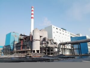
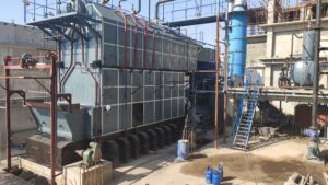
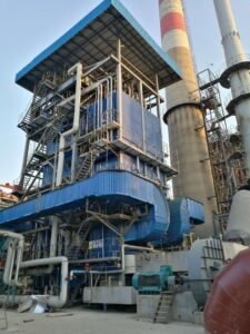
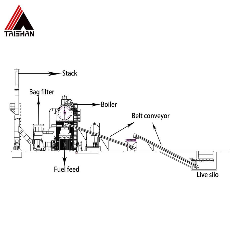
A biomass power plant boiler is a steam generator that burns organic solid fuels — wood, agricultural residues, bagasse, palm kernel shell, rice husk, and others — to raise high-pressure steam for electricity generation or combined heat and power. Capacities typically run from roughly 4 t/h up to 130 t/h steam output, with steam pressure between 1.25 MPa and 13.7 MPa depending on plant size and cycle design. Thermal efficiency ranges from about 82% to 90%, largely determined by fuel moisture content and combustion technology.
What makes biomass combustion genuinely harder than coal or gas firing isn’t the heat — it’s the variance. The same plant may burn three different fuels across a single calendar year, each with a different moisture level, ash fusion temperature, and bulk density. Understanding what a biomass boiler is structurally, and which fuels it can handle without de-rating or accelerated fouling, is the right place to start before any capacity calculation or procurement decision.
Fuel Flexibility Decoded: The Full Spectrum of Biomass Fuels a Modern Boiler Can Handle
Biomass is not a single fuel. That sounds obvious, but procurement teams consistently underestimate just how wide the property spread is — the difference in energy density between fresh bagasse and palm kernel shell is roughly 2:1, and moisture content alone can swing combustion efficiency by 8–12 percentage points. Getting the fuel-boiler match wrong means chronic understeaming, accelerated grate wear, or bed agglomeration that forces an unplanned shutdown inside the first operating year.
Woody Biomass: The Benchmark Fuel Category
Wood chips, sawdust, bark, and forestry residues are what most engineers picture when they hear “biomass boiler,” and for good reason — woody fuels combust predictably, have moderate ash content (typically 1–3% dry basis), and low chlorine levels that won’t hammer superheater tubes. As-received LHV for green wood chips runs 9–11 MJ/kg; air-dried chips push that to 12–14 MJ/kg. Moisture is the main variable, and it shifts combustion chamber temperature significantly on a traveling-grate unit.
Wood pellets are a different story. Densified to 600–700 kg/m³, moisture below 10%, LHV consistently 16–18 MJ/kg — they behave almost like a solid fossil fuel in terms of handling and metering. For internationally-sourced fuel supply chains, pellets make the logistics math work: you can ship roughly twice the energy per container compared to raw chips. The trade-off is pellet cost, which in most markets runs 30–60% higher per GJ than equivalent chips. On large power-grade units (say, 50 t/h and above), that premium adds up fast over a 20-year project life.
Sawdust and fine bark residues need attention at the feed system. Bridging in hoppers and inconsistent bulk density cause uneven grate loading. In practice, a live-bottom silo with agitators, rather than a simple gravity hopper, prevents most of these headaches.
Agricultural Residues: High Availability, Demanding Chemistry
Rice husk is abundant across Southeast Asia and South Asia, and its LHV (12–14 MJ/kg) is respectable — but its silica content, often 15–20% of dry ash, creates bed agglomeration problems in bubbling or circulating fluidized bed (CFB) systems. Silica fuses with alkali species from the husk and forms low-melting-point eutectics. The practical consequence: defluidization events, sometimes within a few hundred operating hours if the bed temperature is not tightly managed below 850°C. Traveling-grate configurations handle rice husk more forgivingly, provided the grate bar geometry suits the fine particle size.
Wheat straw and rice straw carry LHV in the 13–16 MJ/kg range but have elevated potassium and chlorine — occasionally K₂O above 25% of ash and Cl above 0.3% dry basis. That combination drives superheater corrosion and deposit fouling at temperatures above roughly 450°C. Straw-fired projects in Northern Europe have dealt with this for two decades; the engineering response is staged air injection to reduce peak gas temperature, wider superheater tube spacing, and sometimes a deliberate cap on steam temperature to extend tube life.
Sugarcane bagasse, fresh from the mill, runs at 50–55% moisture, cutting its as-received LHV to 7–9 MJ/kg. Dried bagasse (below 15% moisture) reaches 15–17 MJ/kg — an entirely different fuel from a combustion standpoint. Most sugar mill cogeneration projects burn bagasse directly without pre-drying, which simply means the boiler must be sized with enough furnace volume to complete combustion before the gases exit the chamber. Undersized furnace volume on a bagasse unit is one of the more common specification errors I see in project tenders.
Energy Crops and Dedicated Biomass Feedstocks
Palm kernel shell (PKS) has earned a strong following in Japanese and South Korean import markets and in Malaysian and Indonesian captive power projects. LHV of 17–19 MJ/kg, ash content below 3%, and relatively low alkali content make it one of the cleaner-burning biomass fuels available. It handles well on both traveling-grate and CFB units and can substitute for coal on a near-equal energy basis in many boiler configurations. The supply chain is well-established enough that PKS is now traded as a commodity fuel, with pricing that tracks international pellet markets.
Palm empty fruit bunches (EFB) are a tougher proposition. High moisture (60–65% as-harvested), fibrous structure, and elevated K and Cl content mean EFB almost always needs pre-drying or shredding before it enters a boiler. Some operators co-fire EFB with PKS to manage moisture and energy density simultaneously — a practical blend that has worked reasonably well on several 20–40 t/h installations across Indonesia and Malaysia.
Miscanthus and switchgrass, popular in European renewable energy programs, have moderate LHV (14–17 MJ/kg dry) and reasonable ash content but share the high-potassium problem with cereal straws. Bamboo is an underused fuel that performs comparably to hardwood chips in most combustion tests, with the added benefit that it is a fast-rotation crop.
Industrial and Municipal Organic By-Products
Paper mill sludge, poultry litter, food processing waste, and manure-derived pellets present the widest moisture variability of any biomass category — 30–70% wb is a realistic range depending on the season, the source process, and whether any mechanical dewatering has been applied. Burning wet sludge directly without pre-treatment is usually self-defeating; below roughly 25 MJ/kg as-received, the fuel can’t sustain auto-ignition and you end up supporting combustion with auxiliary burners, which defeats the economics entirely.
Co-firing wet sludge above 55% moisture directly in a grate boiler, without pre-drying or blending with higher-LHV fuel, typically results in incomplete combustion, elevated CO emissions, and potential boiler trip.True
High moisture content absorbs furnace heat for evaporation, reducing flame temperature below the threshold for stable ignition and carbon burnout. The result is carbon-in-ash carryover, elevated CO in flue gas, and potential trip on low-furnace-temperature interlock.
These fuels almost always work better as secondary co-fire ingredients blended with drier, higher-LHV biomass — wood chips or PKS are common blend partners. The blending ratio needs to be controlled tightly; a fuel management system that monitors real-time moisture at the feed belt is worth the capital cost on any project above about 15 MWth.
Co-Firing with Coal and Biomass Blends
Low-ratio co-firing — 5 to 20% biomass by heat input in a modified coal-fired boiler — has a different design logic than a dedicated biomass unit. The coal boiler does the heavy combustion lifting; the biomass contribution is a regulatory and carbon-accounting measure as much as a technical one. EU markets and several Southeast Asian feed-in tariff schemes incentivize this approach because it leverages existing coal plant infrastructure without full replacement capital.
Going above 20% biomass co-fire ratio starts to stress coal-boiler components that weren’t designed for biomass ash chemistry — particularly when alkali-rich agricultural residues are in the blend. At 30–40% and above, you are in the territory of a genuinely hybrid boiler design that needs dedicated fuel handling, separate feed points, and ash management adjustments.
Fuel Properties at a Glance
| Fuel Type | Moisture Range (% wb) | LHV As-Received (MJ/kg) | Ash Content (% db) | Cl Content (% db) | Recommended Combustion Technology | Key Design Consideration |
|---|---|---|---|---|---|---|
| Wood chips (air-dried) | 20–40 | 9–14 | 1–3 | <0.05 | Traveling grate, CFB | Moisture variability; feed sizing |
| Wood pellets | 6–10 | 16–18 | 0.5–2 | <0.05 | Traveling grate, stoker | Consistent quality; pellet breakage at conveyors |
| Rice husk | 8–14 | 12–14 | 15–22 | 0.05–0.1 | Traveling grate preferred | Silica agglomeration in fluidized beds |
| Rice/wheat straw | 12–20 | 13–16 | 5–12 | 0.2–0.6 | Grate; CFB with care | Superheater corrosion; alkali fouling |
| Bagasse (fresh) | 48–55 | 7–9 | 2–5 | 0.05–0.1 | Spreader stoker, CFB | Furnace volume; drying upstream optional |
| Palm kernel shell | 10–18 | 17–19 | 1–3 | 0.05–0.15 | Traveling grate, CFB | Premium cost; generally low-risk combustion |
| Palm EFB | 55–65 | 6–9 | 4–8 | 0.2–0.5 | CFB with pre-drying | Moisture management; shredding required |
| Poultry litter / sludge | 30–70 | 9–14* | 10–25 | 0.3–1.2 | CFB, co-fire only | Pre-treatment mandatory above ~50% moisture |
| Coal-biomass blend (≤20% biomass) | Variable | Blend-dependent | Variable | Depends on biomass type | Modified coal grate or pulverized | Alkali dilution; separate feed logic |
*Dried or partially dewatered; as-received values below 30% moisture.
The table above summarizes ranges — actual values depend on source region, harvest season, and any upstream processing. Always request a proximate and ultimate analysis from your actual fuel supplier before finalizing boiler sizing. Quoted LHV from a datasheet and measured LHV at the plant gate have surprised more than a few project teams once commissioning started.
Combustion Technology Selection: Grate-Fired vs. CFB vs. Suspension Firing for Your Fuel Profile
Picking the wrong combustion platform for your fuel is one of the more expensive mistakes you can make on a biomass project. A grate boiler fed inconsistent, high-alkali agricultural waste will give you slagging headaches within months. A CFB specified for clean, uniform wood pellets is simply overbuilt — you paid for capability you’ll never use. The selection logic isn’t complicated, but it does require honest fuel characterization first.
Traveling Grate and Vibrating Grate Stoker Boilers
These are the workhorses of the 4–75 t/h range, and for good reason. The mechanical grate tolerates a wide physical variation in fuel — chunk wood, bark, rice husk, bagasse, mixed agricultural residue — as long as particle size stays roughly in the 10–100 mm band and moisture doesn’t push much above 50–55% (wet basis). Above that, you’re fighting drying before you’re doing combustion, and your efficiency drops sharply.
The key design detail that separates a well-engineered grate from a cheap one is under-grate air zoning. A properly zoned grate supplies primary air in independently controlled compartments along the grate length — drying zone forward, ignition zone mid, burnout zone rear. Overfire air (OFA) ports above the fuel bed handle CO burnout and contribute meaningfully to NOx suppression, typically holding NOx below 250–300 mg/Nm³ without SCR on well-controlled units. Ash drops through the grate or is scraped off the rear; fly ash is captured in a cyclone and/or bag filter downstream.
Capital cost is relatively modest, operation is simpler than fluidized bed, and maintenance staff on most industrial sites can manage it without specialized training. For a palm oil mill burning palm kernel shell and fiber, a traveling grate in the 20–35 t/h range is almost always the right starting point.
Bubbling Fluidized Bed (BFB) Boilers
Scale up toward 10–130 t/h and add high-moisture or high-ash fuels — fresh bagasse at 50% moisture, sewage sludge blends, or poultry litter — and the BFB starts to make sense. Bed temperature runs 750–900°C, low enough to keep NOx formation suppressed thermally and hot enough to maintain stable combustion even when fuel heating value swings around.
Silica sand is the standard bed material. It’s cheap and widely available, but with high-alkali fuels like rice straw, you’ll see bed agglomeration — the alkali and silica react to form low-melting-point eutectics that stick particles together and eventually defluidize the bed. This is a real operational risk, not a theoretical one. Mitigation involves monitoring bed pressure drop continuously, blending with lower-alkali fuels, and periodic bed material replacement. Limestone addition handles in-bed SO₂ capture when you have sulfurous fuels in the mix.
Circulating Fluidized Bed (CFB) [Biomass Boilers](https://coalbiomassboiler.com/product/biomass-boilers/)
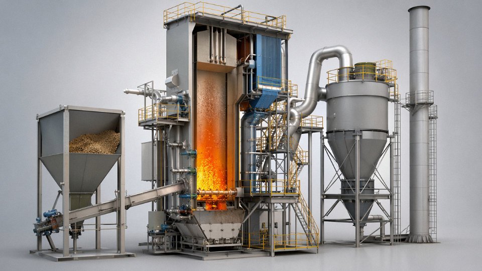
CFB is the most fuel-flexible of the three primary options and the right call when your project involves mixed biomass streams, biomass-coal co-firing, or fuels with elevated sulfur or chlorine. Capacity range overlaps BFB — roughly 20–130 t/h — but the high solids recirculation rate (particles captured by the cyclone separator and returned via the loop seal) extends residence time dramatically, which is why CFB consistently achieves 85–90% boiler efficiency even on variable fuel.
The cyclone separator and loop seal aren’t optional features — they define the combustion loop. Solid particles re-enter the furnace at roughly 800–850°C, maintaining bed inventory and heat transfer even when raw fuel quality dips temporarily. For desulfurization, a Ca/S molar ratio of 2.0–2.5 via limestone injection achieves SO₂ removal of 80–90% in-furnace, which reduces flue gas treatment costs downstream.
High-Cl fuels (some agricultural wastes, RDF blends) still need careful fireside corrosion management at the superheater — steam temperature ceiling tends to be held lower, typically 450–480°C rather than 540°C, unless you specify corrosion-resistant tube alloys.
Suspension Firing / Pulverized Biomass
This technology only works with well-prepared fuel: moisture below 15%, particle size under 3 mm, essentially consistent composition. That means pellets or dried, milled wood powder. The combustion intensity is high and the boiler can be compact for a given output, but the fuel handling and preparation system — dryers, mills, pneumatic conveying — adds capital and operating cost that only makes economic sense above roughly 100 MWe in dedicated power applications, or when you’re co-firing in an existing pulverized coal plant where the infrastructure already exists.
CFB biomass boilers achieve 85–90% thermal efficiency with mixed biomass fuels due to high solids recirculation extending particle residence time.True
The cyclone-loop seal recirculation loop returns unburnt char and bed material to the combustion zone, increasing carbon burnout efficiency. This is well-documented in fluidized bed combustion literature and consistent with operating plant data for properly designed CFB units.
Technology Selection Decision Matrix
| Technology | Capacity Range | Fuel Moisture Tolerance | Particle Size Limit | Fuel Flexibility | Typical Efficiency | Capex Level | Best Application |
|---|---|---|---|---|---|---|---|
| Traveling / Vibrating Grate | 4–75 t/h | Up to ~55% wb | 10–100 mm | Moderate | 82–88% | Low–Medium | Uniform woody biomass, rice husk, palm residue |
| BFB | 10–130 t/h | Up to ~60% wb | Up to ~50 mm | Medium–High | 83–88% | Medium | High-moisture or high-ash fuels, bagasse, sludge blends |
| CFB | 20–130 t/h | Up to ~50% wb | Up to ~30 mm | High | 85–90% | Medium–High | Mixed biomass, biomass-coal blends, high-S/Cl fuels |
| Suspension / Pulverized | >100 MWe typically | <15% wb required | <3 mm required | Low (pellets/powder only) | 88–92% | High | Large dedicated power, co-firing in existing PC plants |
How the Fuel Analysis Review Actually Works in Practice
Before any technology recommendation goes to a client, the engineering team runs through proximate analysis (moisture, volatile matter, fixed carbon, ash), ultimate analysis (C, H, N, S, Cl content), and critically, ash fusion temperatures. A low ash deformation temperature — say, below 1050°C — is a red flag for slagging on a grate or superheater fouling in a CFB.
Chlorine content above roughly 0.3% by weight on a dry basis triggers a corrosion risk review for the superheater design. Alkali index (sum of K₂O and Na₂O in the ash, expressed relative to fuel heating value) above about 0.17 kg/GJ puts you into the agglomeration risk zone for BFB. These aren’t arbitrary thresholds — they’re derived from operating experience with fuels that have caused actual unplanned shutdowns.
Getting complete fuel data from the client is always a negotiation. Some customers send a single proximate analysis from a sample taken years ago. In practice, we ask for seasonal samples if the fuel supply varies — bagasse composition shifts meaningfully between early and late crushing season, and rice husk from different mills can vary by several points in ash content. That variability has to be designed around, not ignored.
Boiler Capacity, Steam Parameters, and Heat Output: How to Size a Biomass Power Boiler Correctly
Sizing a biomass boiler wrong is expensive in both directions. Undersized, and you’re throttling turbine output every time fuel moisture ticks up in the wet season. Over-specified, and you’ve paid for pressure vessels and feed-pump capacity you’ll never use, while fighting a boiler that hunts at part load. The engineering logic here is straightforward — it just requires discipline about fuel data, which is where most projects slip.
The Core Sizing Equation
Required steam output (t/h) = [net heat demand (kW) × 3,600] / [steam enthalpy rise (kJ/kg) × boiler efficiency]
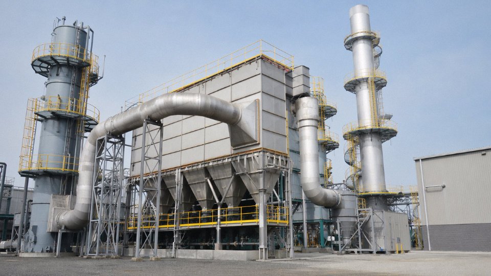
Walk through a real case: a 12 MWe biomass power plant burning rice husk, targeting a condensing-turbine configuration. Assume a turbine heat rate of roughly 11,500–12,500 kJ/kWh (realistic for small biomass Rankine cycles at this scale), so gross thermal input to the cycle sits around 138–150 MWth. The boiler itself needs to deliver steam at, say, 3.82 MPa / 420°C — enthalpy around 3,255 kJ/kg — against feedwater at roughly 130°C (enthalpy ≈ 546 kJ/kg), giving a steam enthalpy rise of about 2,709 kJ/kg. At 85% efficiency on a traveling-grate unit with rice husk at 12–13 MJ/kg LHV and 12–18% moisture, you land somewhere between 52 and 60 t/h steam output required. That’s why most 12 MWe rice-husk plants end up specifying a 65 t/h boiler rather than the 50 t/h unit that looks cheaper on the quotation sheet. The margin is not padding — it’s real operating range to absorb fuel quality variation.
Steam Pressure and Temperature Tiers
For small CHP and process-heat projects — sugar mills, palm oil mills, industrial campuses — medium-pressure steam at 1.25 to 3.82 MPa with temperatures from saturated up to around 450°C is usually the right call. It keeps tube-wall temperatures in a range where alkali chlorides from agricultural fuels (rice husk, straw, bagasse) don’t cause aggressive fireside corrosion, and the lower-grade turbine and feed-pump equipment is easier to source and maintain locally.
Grid-export power plants are a different story. High-pressure configurations at 6.3–9.8 MPa with superheat to 480–540°C meaningfully improve Rankine cycle efficiency — you gain 3–5 percentage points on overall plant efficiency, which matters over a 25-year asset life. But those gains come with real metallurgical commitments: you need alloy superheater tubes (TP347H or similar), more stringent water treatment, and careful fuel screening. Biomass with high alkali and chlorine content — and that’s a lot of agricultural residues — will attack superheater surfaces faster at the high metal temperatures that 540°C steam demands.
Supercritical operation is technically possible but rarely justified for biomass-only plants. The corrosion mechanics at >22 MPa with alkali-rich fuels are punishing, the capital cost jumps sharply, and the O&M expertise required is genuinely scarce outside of large utility operators.
Turbine Configuration and What It Means for Boiler Spec
Back-pressure turbines exhaust at process-steam pressure — common in paper mills and textile plants that need 0.3–0.8 MPa steam downstream. The boiler inlet parameters drive power output, and you have almost no flexibility to decouple heat and power. Extraction-condensing turbines are more forgiving: you extract steam at intermediate pressure for process use and condense the remainder for power, which lets you adjust the heat-to-power ratio seasonally or with load changes. District heating projects and integrated sugar mills almost always benefit from this configuration. Pure condensing turbines maximize electrical output but discard the thermal efficiency advantage of CHP — fine for grid-export projects where power price justifies it.
The turbine choice feeds back directly into boiler specification. A back-pressure turbine for a paper mill might only need 2.5 MPa / 350°C; the same fuel supply configured for grid export needs 9.8 MPa / 540°C. Two completely different boilers, same tonnage.
Fuel Consumption and What It Sizes Downstream
A 25 t/h boiler at 3.82 MPa / 450°C burning wood chips at 13 MJ/kg LHV and 30% moisture (as-received) will consume roughly 4.5–5.0 t/h of fuel. That’s 108–120 tonnes per day. Fuel silo sizing typically targets 3–7 days of storage depending on supply chain reliability — so you’re looking at 325–840 m³ live storage capacity, depending on bulk density (wood chips run 150–300 kg/m³, which is a wide range that depends on species and chip geometry). Belt conveyors, rotary feeders, and spreader stokers all get sized from that fuel feed rate, not from the boiler nameplate. Undersized conveyors are a chronic plant-floor problem — they’re cheap to get right at the design stage and expensive to retrofit.
Sizing Mistakes Worth Avoiding
The most common error I see in project specs is selecting steam pressure by analogy to coal boilers — plants that have run coal often default to 9.8 MPa because that’s what they know, without accounting for the corrosion behavior of their actual biomass fuel. Another is ignoring seasonal moisture swing. A fuel contract that specifies “≤35% moisture” may deliver 45% moisture in the rainy season, drating boiler output by 8–12% precisely when agricultural processing demand peaks.
Auxiliary power consumption also gets underestimated. Fuel handling (crushers, conveyors, vibrating screens), induced-draft and forced-draft fans, flue-gas cleaning (electrostatic precipitators or baghouses), and ash handling systems together consume 6–10% of gross plant output on a biomass plant — meaningfully more than on a gas-fired equivalent.
A biomass power boiler sized only to nameplate steam demand without fuel moisture margin will frequently run below rated output in real operation.True
Fuel moisture directly reduces the effective LHV available for steam generation; a 10-percentage-point increase in as-received moisture (e.g., from 30% to 40%) typically reduces boiler heat release by 8–13%, requiring either oversized boiler capacity or accepted output derate.
Standard capacity steps available — 4, 6, 10, 15, 20, 25, 35, 45, 65, 75, and 130 t/h — cover the range from small industrial CHP to utility-scale biomass power, with pressure-temperature combinations matched to each capacity tier. Projects with unusual fuel profiles, phased capacity expansion requirements, or co-firing arrangements generally need custom engineering rather than a catalog selection, and that conversation should start with fuel analysis data, not a nameplate.
Boiler System Architecture: Pressure Parts, Fuel Handling, and Critical Auxiliary Equipment
A biomass power boiler is not a single piece of equipment — it’s an integrated island of interconnected systems, and the difference between a reliable plant and a chronic maintenance headache usually comes down to how well those systems were specified and coordinated from the start. EPC contractors who buy the boiler proper from one vendor and bolt on third-party auxiliaries afterward tend to discover mismatches the hard way: undersized ID fans starving the combustion zone, fuel conveyors dumping oversized chips directly onto a spreader stoker, or a baghouse sized for coal-grade dust loading that plugs within weeks on rice husk ash.
Pressure Parts Circuit
The steam-side circuit runs: feedwater → economizer → steam drum (with downcomers and risers forming the evaporator loop) → primary superheater → final superheater → steam outlet. Most biomass boilers in the 10–130 t/h range use natural circulation evaporators; forced circulation shows up above roughly 9.8 MPa or where the furnace geometry forces long, low-slope riser paths.
Attemperator spray control sits between the primary and final superheater stages. This is standard practice, but in biomass applications it matters more than in a coal boiler because fuel moisture swings — a load of wet bagasse at 52% moisture versus a dry palm kernel shell delivery at 12% — can shift furnace exit gas temperature by 60–90°C, and without aggressive spray control you’ll overheat the final superheater quickly.
Tube metal temperature at the final superheater is intentionally kept below roughly 580°C surface temperature, even when steam outlet is 480–540°C. Biomass flue gas carries chlorine compounds — HCl concentrations of 200–800 mg/Nm³ are common with agricultural fuels — and chlorine-induced high-temperature corrosion on superheater tubes is the single most common cause of forced outages in biomass plants worldwide. Alloy selection is not optional here: T91 (9Cr-1Mo) handles the lower-temperature superheater stages adequately; TP347H (stabilized 18Cr-10Ni) is preferred for the final superheater where surface temperatures approach the limit. Some plant operators add a thin co-extruded Alloy 625 cladding on the highest-exposure tubes — expensive upfront, but the math usually works out when you’re replacing bare T91 tubes every 18 months.
Fuel Receiving, Storage, and Preparation
Fuel handling starts at the gate. A properly designed fuel reception area handles truck unloading (typically via tipping platforms or grab cranes into a receiving pit) and in larger plants, rail unloading as well. Covered storage bunkers sized for 3–7 days of inventory are the practical standard — less than 3 days and a single supplier disruption shuts the plant; more than 7 days becomes a fire risk, particularly with high-moisture agricultural fuels that can self-heat.
Belt conveyors carry fuel through magnetic separators (tramp metal will destroy a hammer mill impeller in seconds — this is not a component to value-engineer out) and trommel screens that remove oversize material. Hammer mills or rotary shredders reduce fuel to the size fraction the combustion system requires: spreader-stoker furnaces typically want particles under 50 mm, CFB bed injectors need material under 30–40 mm and ideally uniform enough not to segregate in the fluidized bed. Screw feeders handle dense, cohesive fuels like wet sludge or bagasse; pneumatic injection suits lighter, drier materials like rice husk where bridging in a screw is a recurring problem.
Air and Gas Systems
FD fans supply primary and secondary combustion air; in a grate-fired unit, primary air goes under the grate for undergrate combustion, secondary air enters above the fuel bed to complete burnout of volatiles. An air preheater — rotary regenerative type for larger units, tubular for smaller ones — recovers heat from exiting flue gas and raises incoming combustion air temperature by roughly 80–150°C depending on plant size and flue gas exit temperature. That heat recovery typically accounts for 2–4 percentage points of overall boiler efficiency, so it’s not a trivial item to omit.
ID fans handle the full flue gas volume including any recirculated gas, and they need to be sized with a margin for higher-than-design moisture fuel — a common specification oversight. Undersized ID fans are probably the most frequent cause of load-limiting in biomass plants I’ve seen.
Flue-Gas Cleaning Train
Emissions control follows a defined sequence. A cyclone or multicyclone collector removes coarse particulate first — this protects the downstream equipment and allows fly ash to be separated by density fractions, which matters if the coarser fraction has fertilizer value. The second stage is either an electrostatic precipitator (ESP) or a fabric filter baghouse; both can achieve PM emissions below 30 mg/Nm³, but baghouses generally perform more reliably with biomass fly ash, which tends to have high resistivity and poor electrical properties that reduce ESP collection efficiency unpredictably.
A fabric filter baghouse consistently achieves lower particulate emissions than an ESP when handling biomass fly ash with high resistivity.True
Biomass fly ash, particularly from agricultural residues, often has electrical resistivity above 10¹² Ω·cm, which causes back-corona in ESP fields and reduces collection efficiency. Fabric filters are not affected by ash resistivity and typically achieve PM emissions of 10–25 mg/Nm³ on biomass regardless of fuel type.
Acid gas control — HCl and SO2 — is handled by a semi-dry scrubber (lime slurry injection) or a dry sorbent injection system upstream of the baghouse. For plants targeting EU Industrial Emissions Directive compliance, HCl limits are typically 10 mg/Nm³ on a daily average, which is tight enough that you need consistently good sorbent distribution and contact time.
SNCR with urea solution injection into the furnace at 850–1050°C is the standard NOx reduction approach for biomass boilers below about 50 MWth, targeting NOx below 200 mg/Nm³. SCR is occasionally applied on larger or more sensitive sites, but the cost and catalyst management complexity rarely justify it at this scale unless regulations specifically require it.
Ash Handling
Bottom ash from grate plants or bed drain material from CFB systems is typically coarse enough to handle by drag chain conveyor or screw conveyor to an enclosed bottom ash silo. Fly ash — collected from economizer hoppers, air preheater hoppers, and the ESP or baghouse hoppers — is finer and transported pneumatically to a separate fly ash silo.
Biomass fly ash from wood or agricultural fuels can be land-applied as a soil amendment in many jurisdictions, which reduces disposal costs significantly. The caveat is heavy metal content: fuels like demolition wood waste or sewage sludge co-fire can push cadmium, lead, or zinc levels above regulatory thresholds for agricultural use. Get a fuel-specific ash analysis before assuming the fertilizer pathway is available.
Instrumentation and Control
A DCS-based combustion management system handles fuel feed rate, air-to-fuel ratio through oxygen trim, steam temperature control via attemperator, and grate speed or bed inventory management. For CFB units, bed temperature monitoring (typically 850–900°C target) is a primary control variable. Safety interlocks and pressure vessel compliance follow ASME Section I for export to the Americas, PED 2014/68/EU for European projects, or GB/T 16507 for domestic Chinese installations — specify the applicable code at contract stage, not during detailed engineering, because it affects documentation, material traceability, and inspection requirements throughout the entire manufacturing process.
Emissions Performance and Regulatory Compliance for Biomass Power Boilers
Emissions are where a lot of biomass projects get into trouble — not because the boiler supplier ignored the topic, but because the buyer didn’t specify the regulatory target clearly at the front end, and the compliance gap only becomes visible at commissioning. By then, retrofitting an SCR or upgrading a baghouse is expensive and causes schedule pain.
What Biomass Combustion Actually Produces
Biomass is not a clean fuel in the naive sense. It generates particulate matter, NOx, CO, SO₂, HCl, and — if waste-derived fractions enter the fuel mix — dioxins and furans. The relative weight of each pollutant shifts dramatically with fuel type, which is why a single generic emissions control package rarely fits every project.
Particulate matter is the most universal concern. Fine fly ash from rice husk and agricultural straw is notoriously hard to capture; particle size distributions skew finer than wood-chip combustion, which means a simple multicyclone is inadequate regardless of what some low-cost quotations suggest.
NOx comes from two overlapping mechanisms. Thermal NOx forms when flame temperatures exceed roughly 1,300 °C — less of an issue with high-moisture biomass, but real with dried wood pellets or palm kernel shell. Fuel-bound nitrogen is the dominant pathway in straw, bagasse, and most agricultural residues, where nitrogen content in the fuel ranges from 0.3% to over 1.5% by weight. Both pathways must be considered in the control strategy design, not just one.
SO₂ tends to be low in clean woody biomass — sulfur content is usually below 0.1% — but agricultural residues tell a different story. Rice straw can carry 0.1–0.2% sulfur, and bagasse from some regions runs higher. HCl is the sleeper problem: straw, empty fruit bunch (EFB), and other chlorine-rich fuels release HCl in the furnace that corrodes superheater tubes and requires active flue-gas treatment downstream. Chlorine content in EFB can reach 0.3–0.5% on a dry basis; that translates to HCl concentrations in the raw flue gas that will fail EU IED limits without sorbent injection.
CO is essentially a combustion quality indicator. Elevated CO almost always points to poor fuel distribution, low furnace temperature, or excess moisture — problems that show up in emissions data before they show up as efficiency losses on the heat balance.
Dioxins and furans are only relevant when the fuel stream contains waste-derived materials: municipal solid waste co-firing, contaminated demolition wood, or sewage sludge. For a pure agricultural or forestry biomass boiler, dioxin control is not the primary design driver, but any plant that might ever co-fire waste fractions should have the flue-gas temperature profile and residence time designed to meet the 850 °C/2-second rule from the outset.
Primary NOx Control: Starting Inside the Furnace
Before adding any reagent injection system, the combustion design itself should do as much work as possible. Staged combustion — splitting the combustion air into primary undergrate air and secondary overfire air (OFA) — reduces peak flame temperature and limits fuel-N conversion. On a well-tuned traveling-grate boiler, OFA typically accounts for 20–35% of total combustion air. Flue-gas recirculation (FGR) adds another layer of thermal NOx suppression, particularly useful on high-calorific fuels like palm kernel shell or wood pellets where furnace temperatures are inherently higher.
Low excess-air operation sounds obvious, but in practice many plant operators run excess air at 30–40% above stoichiometric because they’re nervous about CO exceedances. That’s a reasonable conservative startup practice, but staying there long-term pushes NOx up and drops efficiency. Optimizing excess air to roughly 15–25% at steady-state — once combustion stability is confirmed — is the right operating band for most grate-fired biomass units.
SNCR and SCR: Secondary Treatment When Primary Measures Aren’t Enough
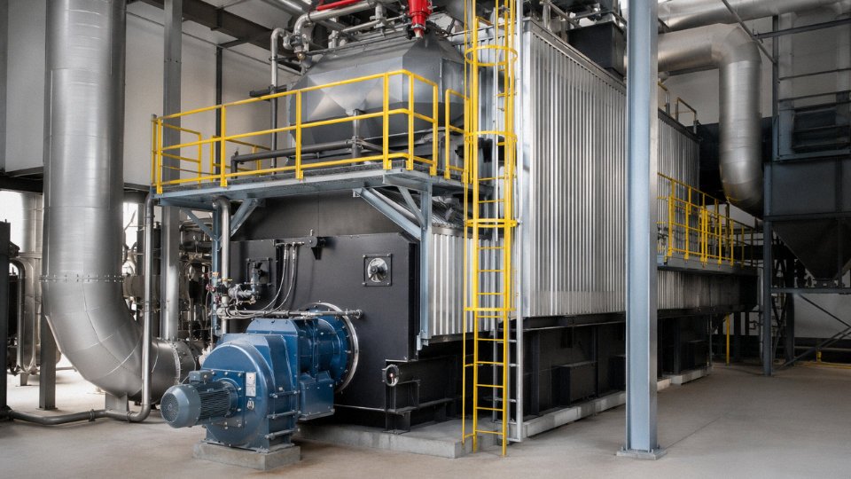
When primary measures get NOx down to the 300–400 mg/Nm³ range and the permit requires 200 mg/Nm³ or less, SNCR is the standard solution. Aqueous urea at 32.5% concentration is injected into the furnace flue-gas stream at the temperature window where the selective non-catalytic reaction works — typically 850–1,050 °C. Reduction efficiency is 40–60% under real operating conditions, not the 70% that some vendors quote from ideal lab data. The actual figure depends on flue-gas temperature uniformity, reagent distribution (lance design matters), and load stability.
Targeting <200 mg/Nm³ NOx at 6% O₂ is achievable with SNCR on a well-controlled boiler. Getting below 100 mg/Nm³ requires SCR — a catalyst bed installed downstream, typically between the economizer and air preheater at 300–400 °C. SCR adds meaningful capital cost (catalyst modules, reactor vessel, ammonia or urea handling) and ongoing catalyst replacement expense, but for projects selling into EU markets or co-firing with waste fractions under IED scrutiny, it’s increasingly unavoidable.
Particulate and HCl Control: The Baghouse Is Non-Negotiable
A fabric filter (baghouse) is the right choice for PM control on any serious biomass power boiler. It routinely achieves outlet PM below 10 mg/Nm³ — well inside EU IED limits for large combustion plants — and it provides the necessary contact time and filter cake for dry sorbent injection (DSI) to work effectively.
DSI with hydrated lime Ca(OH)₂ or sodium bicarbonate (NaHCO₃) injected upstream of the baghouse controls HCl and SO₂ simultaneously. For straw-fired or EFB-fired boilers, this combination is essentially mandatory. Hydrated lime is cheaper; sodium bicarbonate achieves better HCl removal efficiency (particularly below 150 °C flue-gas temperature) but costs more per tonne of reagent. The choice depends on permit limit severity and local reagent availability — in Southeast Asia, lime is usually the practical answer.
Electrostatic precipitators (ESPs) are an alternative, but baghouses outperform ESPs on fine particulate from agricultural fuels and integrate more naturally with DSI. Unless plant layout constraints force an ESP, a pulse-jet baghouse is the better specification for biomass.
International Emission Benchmarks: A Working Comparison
The regulatory landscape varies considerably across the markets where biomass power plants are being built. Oversimplifying it is a procurement risk.
| Region / Regulation | PM (mg/Nm³) | NOx (mg/Nm³) | SO₂ (mg/Nm³) | HCl (mg/Nm³) | Reference O₂ |
|---|---|---|---|---|---|
| EU IED (>50 MWth, LCP) | 20 | 200 | 200 | 10 | 6% |
| EU MCP BAT (1–50 MWth) | 20–50 | 200–650 | 200–400 | — | 6% |
| Thailand (biomass power) | 80–120 | 200–350 | 200–320 | not specified | varies |
| Indonesia (biomass power) | 100 | 800 | 750 | not specified | 7% |
| Vietnam (QCVN 19) | 100–200 | 850 | 500 | not specified | varies |
| India (biomass power, MoEF) | 50–100 | 300–400 | 200–600 | not specified | 7% |
Limits shown are indicative for solid biomass combustion; always verify against the current national gazette and site-specific permit, as these standards are actively tightening in all four ASEAN markets.
The gap between Indonesian and EU limits looks comfortable on paper. In practice, projects seeking carbon credits, export power agreements, or ESG financing increasingly face lender requirements that reference EU BAT conclusions regardless of local law. Specifying the boiler and flue-gas treatment system to EU IED levels from the start costs less than a retrofit two years later.
SNCR with 32.5% aqueous urea can achieve 40–60% NOx reduction on biomass boilers under real operating conditions.True
This range is consistent with published SNCR performance data for grate-fired and CFB biomass boilers operating within the optimal temperature window (850–1,050 °C). Actual reduction depends on flue-gas temperature uniformity, reagent mixing quality, and load stability; the 70%+ figures sometimes quoted by vendors typically reflect idealized test conditions.
Ash Quality and By-Product Value
Bottom ash from wood-chip or pellet-fired boilers is usually low in heavy metals and leachable contaminants, making it suitable as a soil amendment or minor cement constituent in most jurisdictions — worth checking against local waste classification rules, but generally manageable and sometimes revenue-generating. Rice husk ash is a different story in the best way: high amorphous silica content (70–90% SiO₂ depending on combustion temperature) makes it valuable to concrete admixture producers and refractory manufacturers. A 30 t/h rice husk boiler generating 4–6 t/day of ash can offset disposal costs entirely and generate a modest side income if an off-take agreement is arranged before plant commissioning.
Fly ash from agricultural residues, particularly straw, requires more careful handling due to elevated potassium and chlorine content — direct land application without stabilization can cause soil pH and salinity issues.
Emissions Guarantees in Supply Contracts
Emissions performance should be a contractual deliverable, not a sales conversation. The standard practice is to write design emission levels into the supply contract with acceptance criteria tied to a third-party stack test at commissioning, conducted by a certified laboratory using reference measurement methods (EN 13284 for PM, EN 14792 for NOx, and equivalents). SNCR system sizing is done from site-specific flue-gas volumetric flow calculations and measured or design-basis NOx inlet concentrations — not from a generic template. Any supplier who cannot provide the basis of their SNCR sizing calculation during the proposal stage is a red flag.
Thermal Efficiency, Operating Costs, and Fuel Economics Over the Plant Lifecycle
Efficiency in a biomass boiler is not a single number on a datasheet — it’s a moving target that shifts with fuel quality, load factor, and how well the plant is maintained month to month. The gross thermal efficiency figure (heat absorbed by steam divided by heat released from fuel combustion) runs 82–88% for traveling-grate units and 85–90% for CFB biomass boilers under favorable conditions. Those upper bounds assume dry, consistent fuel, well-tuned combustion air, and clean heat transfer surfaces. In practice, most plants operate somewhere in the middle of those ranges, and a few drift below them by the end of a long campaign between outages.
How Fuel Moisture Punishes Efficiency — and Fuel Costs
Moisture is the single biggest lever on operating economics that plant owners routinely underestimate at the project-development stage. Every 10 percentage-point increase in fuel moisture content (wet basis) costs roughly 2–3 efficiency points, because a growing share of combustion heat goes into vaporizing water rather than raising steam. That sounds modest until you work through the fuel consumption math.
Consider a 25 MWe biomass power plant running at 35% net electrical efficiency with a 10% boiler thermal loss. At full load, the plant needs roughly 5.5–6.5 t/h of wood pellets (LHV around 16–17 MJ/kg) or 7.5–9 t/h of fresh bagasse — the wide range within each fuel type is almost entirely driven by the actual moisture content delivered to the bunker that day. Switch from 15% moisture wood chips to 45% moisture chips from a wet season harvest, and your fuel consumption rate climbs by 15–20% for the same steam output. The trucks keep arriving more often, the conveyors run harder, and the ID fan draws more power against the heavier flue-gas volume. None of that appears on the nameplate.
At USD 80/t for wood pellets, fuel cost alone runs USD 440–520/h at full load. That’s the dominant cost driver — typically 60–70% of the levelized cost of energy for biomass power, which is why fuel supply contracts and moisture specifications deserve as much attention as the boiler specification itself.
Measures That Actually Move the Efficiency Needle
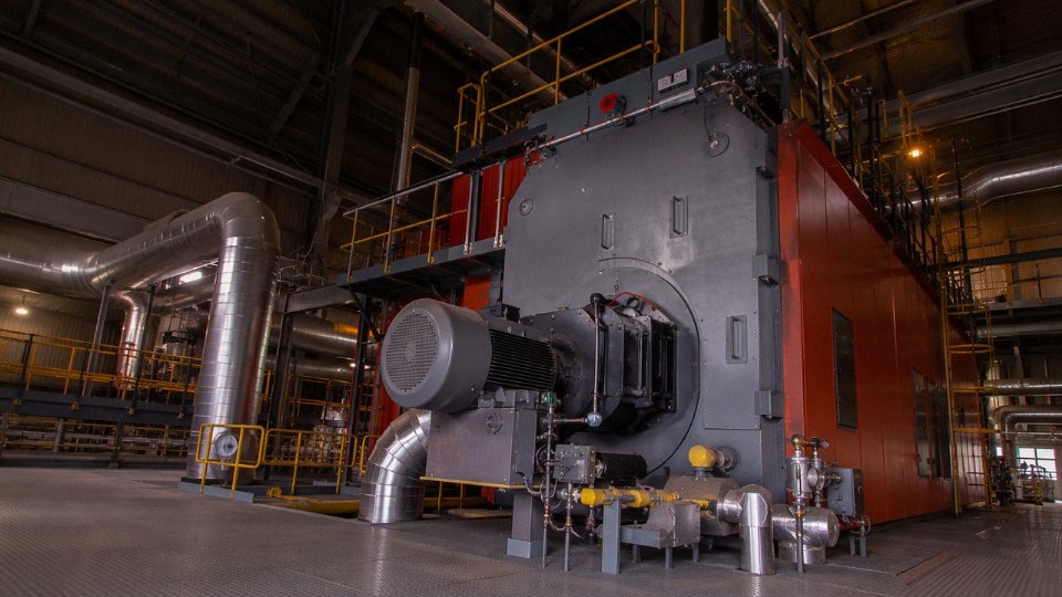
An air preheater recovering 15–25°C from flue gas before stack exit is one of the more cost-effective upgrades, especially when firing high-moisture agricultural residues where exit temperatures can creep toward 180–200°C without it. In combined heat and power (CHP) configurations, integrating turbine exhaust heat into a process steam or hot water loop lifts overall fuel utilization to 75–85% — that’s the regime where the economics of biomass genuinely become compelling compared to separate generation and process heating.
Online soot-blowing matters more than many operators acknowledge. Superheater and evaporator surfaces foul progressively with ash deposits, particularly when firing potassium-rich fuels like straw or rice husk. A boiler that ran at 87% efficiency in week one can quietly slip to 83% by week eight if soot-blowing is being skipped to “save steam.” Condensate return deserves equal attention in process-heat plants — every tonne of condensate recovered is demineralized water and thermal energy that doesn’t have to be replaced.
Auxiliary Power and What It Does to Net Output
Auxiliary power consumption — FD and ID fans, fuel conveyors, ash handling systems, water treatment, and emissions control equipment — typically consumes 3–6% of gross electrical output. That range widens toward 6% for CFB units with higher fan pressure requirements and for plants running bagasse or high-ash rice husk with demanding ash extraction. For a 25 MWe gross plant, that’s 750 kW to 1.5 MW of parasitic load — significant enough to move the project financing numbers if it’s glossed over in the feasibility model.
Auxiliary power consumption for a biomass CFB boiler plant typically represents 3–6% of gross output, reducing bankable net capacity accordingly.True
CFB combustion requires higher fan static pressures than grate-fired units, and biomass fuel handling (size reduction, conveying, ash extraction) adds meaningful electrical load compared to coal plants of equivalent capacity. This range is consistent with published performance data from operating biomass power projects.
Maintenance Costs: Budget Realistically
Planned annual shutdowns run 5–7 days for grate-fired boilers and 7–14 days for CFB units, the latter requiring more thorough refractory inspection and cyclone wear-part replacement. Major wear items on grate boilers are the grate bars themselves — depending on fuel ash content and combustion temperature, a full grate bar replacement cycle might fall anywhere between 18 months and 4 years. On CFB units, the nozzle plate and cyclone liner wear are the budget items that catch operators off-guard if they weren’t sized for the actual fuel’s silica or alumina content.
Superheater tube inspection for corrosion thinning is non-negotiable in plants firing chlorine-rich fuels (straw, municipal sludge blends, demolition wood). High-temperature chlorine corrosion can thin tubes by 0.3–0.8 mm per year in worst-case firing conditions — annual ultrasonic thickness surveys are cheap compared to an unplanned tube failure mid-campaign.
A realistic annual maintenance budget for a 25–35 t/h unit sits in the USD 150,000–400,000 range, with the upper end applying to CFB units, aggressive fuels, and plants in humid climates where refractory degrades faster during cold shutdowns.
The Total Cost Picture Against Coal and Gas
For a 20 MWe power plant, biomass carries higher fuel-handling CAPEX and O&M than natural gas, but the fuel cost per GJ is usually competitive with gas in markets where pipeline gas is priced above USD 8–10/GJ. Against coal, biomass is broadly comparable on fuel cost in Southeast Asia and South Asia where agricultural residues are locally abundant and cheap.
The variable that changes the business case most sharply is renewable energy revenue. Carbon credits, feed-in tariffs (Thailand’s biomass FiT has historically run in the range of THB 3.5–4.5/kWh above the base rate, depending on the scheme period), Renewable Obligation Certificates in the UK, and RECs in India can offset 15–35% of total project LCOE in favorable policy environments. That offset is why biomass power projects that look marginal on pure fuel economics often pencil out well once the full revenue stack is included — and why buyers selecting a boiler supplier should be asking for performance guarantees that actually support a bankable revenue model, not just a nameplate efficiency figure.
EPC Project Delivery: From Fuel Analysis and Site Survey to Commissioning and Performance Testing
Buying a biomass boiler as standalone equipment is straightforward. Buying a working power plant — one that meets local emissions codes, integrates cleanly with a turbine-generator set, and actually achieves the guaranteed steam output on your specific fuel — is a different problem entirely. Most project failures I’ve seen don’t come from bad boilers. They come from mismatched fuel assumptions, incomplete auxiliary scopes, and no single party accountable for the whole thing.
Phase 1: Fuel Characterization and Feasibility
Before any equipment is specified, the fuel has to be understood in detail. Proximate analysis (moisture, ash, volatile matter, fixed carbon) and ultimate analysis (C, H, O, N, S, Cl) are baseline. What gets skipped surprisingly often is ash fusion temperature testing — critical for grate-fired units running agricultural fuels with high potassium content, where slagging at 900–1,050°C can shut a plant down within weeks of commissioning. Chlorine and alkali index calculations follow directly from the ultimate analysis and determine whether superheater tube wastage is a foreseeable maintenance issue or not.
The fuel supply chain audit matters just as much as the lab work. Seasonal moisture swings of 15 to 30 percentage points are routine for rice straw or bagasse in tropical climates — and that swing directly changes combustion behavior, bed temperature stability in a CFB, and achievable steam output. Transport distance, storage method, and how many suppliers are in the chain all affect how stable that fuel actually is over a 20-year plant life.
Taishan provides a structured fuel assessment report at no charge for qualified project inquiries. It’s not a gesture — it’s the document that determines whether the project is technically viable before anyone commits capital.
Phase 2: Engineering Deliverables
Basic engineering produces the process flow diagram, heat and mass balance, and preliminary equipment layout. Detailed engineering goes further: P&IDs, civil and structural load drawings, electrical single-line diagrams, and the instrumentation architecture for the DCS. All of this is produced with the client’s local permitting requirements in mind — CE marking and PED compliance for European projects, ASME stamp for North American or Latin American buyers, SNI certification for Indonesia, IS standards for India. Regulatory alignment at the engineering stage avoids expensive rework during permitting, which can add months to a project schedule.
Phase 3: Procurement and Manufacturing
All pressure parts — drums, headers, membrane panels, superheater bundles — are fabricated in Taishan’s ISO 9001 and PED-certified workshops. Third-party inspection by TÜV, Bureau Veritas, or Lloyd’s Register is available on client request and is honestly worth doing on any project above roughly 20 t/h. Factory acceptance testing with client witness before shipment is standard, not optional.
Taishan's pressure part manufacturing workshops hold ISO 9001 certification and PED compliance, with third-party inspection available through TÜV, Bureau Veritas, or Lloyd's Register.True
These are verifiable certifications tied to documented manufacturing quality systems and third-party audit processes, not marketing language.
Phase 4: Logistics and Site Construction
The boiler supply is modularized where the site logistics allow — reducing field assembly time by a meaningful margin, usually four to eight weeks depending on unit size and access conditions. On-site scope includes refractory installation supervision, piping and valve installation, and full electrical and I&C integration with the turbine-generator package. Civil contractor coordination is part of the project management responsibility, not passed to the client to sort out independently.
Phase 5: Commissioning, Performance Testing, and Operator Training
Cold commissioning — leak testing, interlock checks, DCS loop verification — precedes hot commissioning in a structured sequence. The 72-hour continuous reliability run is what exposes issues that FAT cannot: thermal cycling behavior, fuel feeding consistency under real load, actual bed temperature distribution in a CFB. The performance acceptance test then measures steam output, boiler thermal efficiency, and stack emissions against the contractually guaranteed values. If the numbers don’t match, that’s a supplier problem, not an owner problem.
Operator training runs five days and covers DCS operation, routine maintenance intervals, and emergency shutdown procedures. It’s hands-on, not slide-deck-only. In practice, that training quality is what determines whether the plant runs well in year two, after the commissioning engineers have gone home.
After-sales support includes a 12-month defect liability period, remote DCS monitoring capability, a recommended critical spare-parts list weighted toward high-wear items (grate bars, bed nozzles, economizer tubes), a 24-hour technical hotline, and on-site maintenance service contracts for clients who want ongoing coverage. The spare-parts list is not generic — it’s sized to your specific fuel’s abrasion and corrosion profile.
Frequently Asked Questions About Biomass Power Plant Boilers
Can a biomass boiler run on multiple fuel types simultaneously, or switch fuels seasonally?
Yes, and this is more common than people assume. Both CFB and traveling-grate biomass boilers are routinely designed with fuel flexibility built into the original thermal specification — not bolted on afterward. In practice, a rice-husk-primary boiler in Southeast Asia might blend palm kernel shell during the off-milling season when husk supply drops, or a European wood-chip unit might co-fire agricultural pellets when forestry residue prices spike.
The engineering requirement is real, though. Switching fuels isn’t just swapping what goes into the hopper. Air distribution curves need adjustment, primary-to-secondary air ratios shift with fuel reactivity, and feed rates change because LHV varies — sometimes by 30–40% between a wet bagasse and a dry pellet. Any fuel blend ratio outside the original design envelope should be reviewed against the boiler’s thermal sizing and your emissions permit conditions before you start. Getting that wrong typically shows up as incomplete combustion, elevated CO, or unexpected slagging on the grate — none of which announce themselves politely.
What is the capacity range, and when does scaling up actually make economic sense?
Industrial biomass boilers start at roughly 4 t/h steam output (around 2–2.5 MWth), which suits small-scale CHP for food processing, sawmills, or rural co-generation. At that scale, fuel handling is simple and civil works are modest.
The economics change meaningfully above about 20 t/h. That’s roughly the threshold where dedicated fuel reception, covered storage, mechanical conveying, and a proper flue-gas treatment system stop being oversized luxuries and start being cost-justified per unit of steam output. For grid-export power projects, most developers end up in the 35–75 t/h range per boiler, sometimes deploying two units for redundancy and load-following flexibility. Utility-scale biomass plants can push individual boiler capacity to 130 t/h. At that point, fuel logistics — not the boiler itself — usually become the project’s critical constraint.
How does high fuel moisture content affect performance, and what are the practical fixes?
Moisture above roughly 50% wet-basis is where operators start feeling real pain. Flame temperature drops, the boiler needs more combustion air to stabilize ignition, and thermal efficiency typically falls 4–6 percentage points compared to the same unit running on 25% moisture fuel. On a poorly managed site, it can cause nuisance trips.
The standard toolkit: rotary drum dryers can pull moisture down to under 30% before the fuel enters the feed system; covered storage prevents seasonal rain absorption that can take a 35% moisture wood chip to 55% overnight in a tropical wet season; and blending dry fuel fractions (pellets, husks) with wet ones is a fast operational fix without capital expenditure. None of these is free — dryer energy use typically runs 8–12% of the fuel’s heating value, so the efficiency gain has to pencil out against that parasitic load.
What pressure vessel certifications does the boiler comply with?
Taishan's biomass boilers are manufactured to Chinese national standard GB/T 16507 as baseline, with optional certification paths including ASME Section I, EU PED 2014/68/EU with CE marking, and third-party inspection under TÜV, BV, or Lloyd's Register.True
GB/T 16507 governs power station boilers in China; ASME Section I, EU PED CE marking, and TÜV/BV/Lloyd's Register third-party inspection are standard international certification routes for export boilers and are technically compatible with the manufacturing process when planned from the design stage.
Which standard applies depends on the destination country and, increasingly, on the project lender’s requirements — some development finance institutions specify ASME or PED regardless of geography. The time to raise this is during front-end engineering, not after the pressure parts are fabricated.
Is biomass combustion carbon-neutral, and does it qualify for incentives?
Biomass from sustainably managed sources is classified as carbon-neutral under IPCC accounting methodology, and most national renewable energy frameworks treat it accordingly. The EU Renewable Energy Directive (RED II), the UK’s Renewable Obligation Certificate scheme, Thailand’s and Vietnam’s feed-in tariff programs, and India’s Renewable Energy Certificate mechanism all include biomass — though eligibility conditions vary, and feedstock sustainability certification is increasingly a hard requirement rather than a recommendation. FSC, PEFC, and RSB are the commonly accepted schemes.
One practical note: project developers who skip sustainability documentation during permitting often discover they’re locked out of incentive revenue at the worst possible moment — after construction.
What is a realistic project timeline from contract to first steam?
For a 25 t/h biomass power boiler on a reasonably straightforward greenfield site: engineering runs 2–3 months, manufacturing 5–7 months, site construction and installation 3–5 months, and commissioning 1–2 months. Total: roughly 11–17 months from contract signing to commercial operation.
That range isn’t vague padding — local permitting timelines, civil foundation complexity, and whether the client’s fuel handling civil works are on the critical path all genuinely move the number. Sites that need significant land preparation or where grid connection approval is slow can easily add 2–3 months to the back end.
How does a biomass boiler differ from an MSW incineration boiler?
They share a family resemblance — both are combustion-based steam generators — but they’re engineered as distinct product lines for good reason. A biomass boiler handles clean, defined organic fuels with known proximate and ultimate analysis; you know the chlorine content, the ash fusion temperature, the sulfur. An MSW boiler (mass-burn moving grate or refuse-derived fuel unit) handles heterogeneous waste where chlorine levels, heavy metals, and dioxin precursors vary batch to batch.
That variability drives the differences in flue-gas treatment complexity: MSW installations typically require activated carbon injection for dioxin and mercury control, two-stage acid gas scrubbing, and compliance with EU Waste Incineration Directive 2000/76/EC limits that are significantly stricter than standard biomass emission limits. The furnace geometry, refractory specification, and heat release rates are also different. Both are within the manufacturing scope here, but a biomass boiler specification should never be quietly stretched to cover MSW without a full redesign of the combustion system and the back-end gas cleaning train.
References
Biopower: Energy for Heat and Electricity
https://www.energy.gov/cmei/fuels/biopower-energy-heat-and-electricity
Source: U.S. Department of EnergyBioenergy Frequently Asked Questions
https://www.energy.gov/cmei/fuels/bioenergy-frequently-asked-questions
Source: U.S. Department of EnergyBiomass Combined Heat and Power Catalog of Technologies: Biomass Conversion Technologies
https://www.epa.gov/sites/default/files/2015-07/documents/biomass_combined_heat_and_power_catalog_of_technologies_5._biomass_conversion_technologies.pdf
Source: U.S. Environmental Protection AgencyBiomass Combined Heat and Power Catalog of Technologies: Biomass Preparation
https://www.epa.gov/sites/default/files/2015-07/documents/biomass_combined_heat_and_power_catalog_of_technologies_4._biomass_preparation.pdf
Source: U.S. Environmental Protection AgencyFact Sheet on Clean Cellulosic Biomass and Non-Hazardous Secondary Materials Determinations
https://www.epa.gov/rcra/fact-sheet-clean-cellulosic-biomass-and-non-hazardous-secondary-materials-determinations
Source: U.S. Environmental Protection AgencyAP-42 Section 1.6: Wood Residue Combustion in Boilers
https://www.epa.gov/system/files/documents/2022-03/c1s6_final_0.pdf
Source: U.S. Environmental Protection AgencyLow-Emission Biomass Combustion in Automated Boilers
https://www.ieabioenergy.com/wp-content/uploads/2024/09/Nussbaumer_IEA-Bioenergy-Task32-Emissions-Report_2024_08_20.pdf
Source: IEA BioenergyAgricultural and Forest Residues: Generation, Utilization and Availability
https://www.fao.org/4/AD576E/AD576E00.htm
Source: Food and Agriculture Organization of the United NationsUnified Bioenergy Terminology
https://www.fao.org/4/j4504e/j4504e10.htm
Source: Food and Agriculture Organization of the United NationsTechnical Manual for the SAM Biomass Power Generation Model
https://docs.nrel.gov/docs/fy11osti/52688.pdf
Source: National Renewable Energy Laboratory