Industry News

Key Factors Influencing Heat Transfer and Combustion Efficiency in Industrial Steam Boilers
Key Factors Influencing Heat Transfer and Combustion Efficiency in Industrial Steam Boilers

Industrial steam boilers are central to manufacturing, energy, and process applications—yet many systems underperform due to unoptimized combustion and heat transfer. Poor combustion control, heat exchanger fouling, or incorrect air-fuel ratios can cause excessive fuel consumption, higher emissions, and reduced steam output. To operate efficiently and sustainably, it’s essential to understand and control the variables that impact both combustion efficiency and thermal performance.

The heat transfer and combustion efficiency in industrial steam boilers are influenced by multiple factors, including burner design, air-to-fuel ratio, flame temperature, fuel quality, flue gas temperature, soot buildup, and surface cleanliness of heat exchangers. Combustion efficiency depends on complete fuel burning with minimal excess air and unburned carbon. Heat transfer efficiency relates to how well heat is absorbed by water or steam surfaces, which can be impaired by fouling, scale, or ash deposits. Regular monitoring and maintenance are critical for sustaining high efficiency.

Let’s dive into the core performance drivers of efficient steam boiler operation.
How Does Burner Design and Fuel-Air Mixing Affect Combustion Efficiency?

In industrial combustion systems, poor fuel-air mixing and outdated burner designs lead to incomplete combustion, higher pollutant emissions, and significant energy loss. These inefficiencies increase operational costs and maintenance demands while hindering regulatory compliance. However, through optimized burner geometry and improved mixing technologies, combustion efficiency can be dramatically enhanced. This article explores how the intricate relationship between burner configuration and air-fuel dynamics can directly influence combustion performance and environmental impact.

Burner design and fuel-air mixing are critical to combustion efficiency because they determine how completely fuel is burned. A well-designed burner ensures turbulent mixing, consistent flame stability, and optimal stoichiometry—conditions that maximize thermal output and minimize pollutants. Poor designs lead to incomplete combustion, higher emissions, and energy losses. Advanced burner technologies, such as swirl-stabilized or staged burners, improve fuel utilization by enhancing air-fuel contact, flame anchoring, and heat distribution.

By exploring real case studies, design principles, and engineering data, the following content delivers practical, technical insights into how burner design choices can dramatically affect fuel economy and environmental performance. Whether you’re a plant manager or thermal systems engineer, this article offers in-depth value you won’t want to miss.

Burner geometry and air-fuel ratio directly influence flame temperature and combustion completeness.True

Proper burner geometry ensures optimal mixing and residence time, while correct air-fuel ratios prevent excess oxygen or fuel, both critical for high-efficiency combustion.

🔥 Understanding Burner Design Fundamentals

Burner design integrates multiple elements—fuel injection mechanisms, airflow channels, flame anchoring systems, and chamber geometry—all of which play key roles in achieving efficient combustion. The interplay of these components determines how well the flame forms, stabilizes, and sustains itself under varying load conditions.

Key Parameters in Burner Design:

Burner ElementFunctionImpact on Efficiency
SwirlersInduce rotational flow to promote turbulent mixingEnhances fuel-air interfacial area
Flame StabilizersAnchor flame at fixed location within burnerPrevents flame blow-off or flashback
Nozzle ConfigurationDetermines spray pattern and droplet size (for liquid fuels)Affects evaporation rate and ignition timing
Primary/Secondary Air ControlsRegulate stoichiometric zonesEnables staged combustion for NOx control
Combustion Chamber GeometryControls residence time and heat feedback loopAffects burnout rate and heat flux

For example, swirl-stabilized burners incorporate angled vanes or blades that introduce a rotational component to incoming air. This swirl generates a central recirculation zone that holds the flame near the nozzle and enhances fuel-air mixing. When designed using CFD (Computational Fluid Dynamics), these burners demonstrate superior flame stability and low emission profiles.

One industrial retrofit in a 300 MW power plant involved replacing straight-flow burners with swirl-stabilized models, leading to a 12% increase in thermal efficiency and a 45% drop in unburned carbon in fly ash.

💨 The Science of Fuel-Air Mixing

Combustion efficiency is governed not just by how fuel is introduced, but also by how well it mixes with air. Proper mixing ensures a uniform air-fuel mixture, which in turn facilitates complete combustion with minimal emissions.

Ideal Air-Fuel Mixing Characteristics:

Mixing ParameterDescriptionEffect on Combustion Efficiency
Turbulent KineticsHigher turbulence increases diffusion ratesAccelerates chemical reactions
Equivalence RatioRatio of actual fuel/air to stoichiometric ratioMust be close to 1 for maximum efficiency
Residence TimeDuration of air-fuel mixture in flame zoneDetermines completeness of reaction
Temperature UniformityReduces thermal NOx formation and heat lossEnsures consistent burnout

For gaseous fuels, high-speed jets create turbulence naturally, but liquid and solid fuels require atomization or pulverization followed by mechanical or aerodynamic mixing strategies. Excess air leads to heat loss, while insufficient air causes unburned fuel. Therefore, precise control over the stoichiometric ratio is essential.

Techniques such as pre-mixed combustion, where fuel and air are blended prior to ignition, and staged combustion, where the mixing occurs in phases, are often deployed to optimize performance. CFD analysis shows that staged burners reduce peak flame temperature by up to 300°C, significantly lowering NOx production.

📊 Burner Performance Analysis: Case Study Data

Burner TypeCombustion Efficiency (%)CO Emissions (ppm)NOx Emissions (ppm)Flame Stability Range (%)
Legacy Burner85.213515070–100
Swirl-Stabilized92.7408050–110
Air-Staged Burner94.5306560–120

This table compares data from a field study involving three different burner systems. It’s evident that swirl-stabilized and staged burners outperform legacy designs significantly, especially in terms of emissions and stability. For industrial users, this translates into not just regulatory compliance but also fuel cost savings.

In a real-world deployment, an air-staged burner retrofit in a chemical refinery slashed CO emissions by over 75% and improved heat recovery in waste heat boilers, raising plant-wide thermal efficiency by 6.3%.

🧪 Advanced Engineering Considerations

Burner design and fuel-air mixing must also address secondary factors like pressure drop, ignition delay, and combustion noise. These are influenced by:

  • Aerodynamic Shaping: Controls flow separation and vortex formation.

  • Acoustic Coupling: Affects flame flicker and noise in high-pressure systems.

  • Catalytic Support Structures: Enhance combustion in low-temperature environments.

Burners designed with integrated swirler blades improve fuel utilization efficiency.True

Swirlers promote turbulent mixing, creating a more uniform and stable flame, which results in higher combustion completeness.

Advanced diagnostics—such as chemiluminescence imaging, Particle Image Velocimetry (PIV), and Fourier infrared spectroscopy—are now used to analyze flame patterns and pollutant formation at a granular level. These tools help engineers refine burner designs and mixing strategies iteratively.

Additionally, modern combustion systems are increasingly integrated with digital twins and machine learning algorithms that adjust air-fuel ratios dynamically in real time, boosting efficiency even under fluctuating loads.

Summary

Optimizing burner design and fuel-air mixing is one of the most impactful strategies for improving combustion efficiency in industrial systems. The shape and structure of burners determine flame stability, mixing intensity, and temperature profiles—all of which directly affect how completely and cleanly a fuel burns. Properly engineered systems reduce fuel consumption, cut emissions, and extend equipment lifespan. By leveraging modern technologies such as CFD modeling, real-time oxygen trim systems, and staged combustion methods, industries can achieve remarkable improvements in thermal performance and environmental compliance.
Why Is Managing Excess Air and Oxygen Levels Key to Complete Combustion?

Combustion systems in boilers, furnaces, and turbines often suffer from invisible inefficiencies caused by poor control of air and oxygen levels. If excess air is too low, incomplete combustion results in soot, carbon monoxide, and unburned hydrocarbons. If it’s too high, thermal energy is wasted heating unused oxygen and nitrogen, increasing stack losses. These issues drive up fuel costs, increase maintenance, and violate emission standards. However, with precise oxygen control and managed excess air, combustion can be optimized for maximum fuel utilization and minimum emissions. This article explains how managing air-to-fuel ratios and oxygen levels is fundamental to complete and efficient combustion.

Managing excess air and oxygen levels is essential for complete combustion because they directly influence flame temperature, chemical reaction completeness, and emission outputs. Too little air leads to incomplete combustion and pollutant formation, while too much air cools the flame and increases heat loss through exhaust gases. Ideal combustion occurs when just enough oxygen is provided to fully oxidize the fuel without overheating or energy waste. This balance ensures higher combustion efficiency, lower fuel usage, and reduced environmental impact.

Achieving this delicate balance requires accurate measurement tools, responsive control systems, and an understanding of combustion dynamics. Read on to discover the science, strategy, and technologies behind one of the most important aspects of thermal process optimization.

Complete combustion requires a stoichiometric or slightly excess air-fuel ratio to fully oxidize fuel.True

A stoichiometric air-fuel ratio ensures all fuel is oxidized; slight excess air ensures complete combustion while allowing a safety margin.

🔬 Combustion Chemistry and the Stoichiometric Point

Complete combustion happens when every molecule of fuel reacts with the exact amount of oxygen needed to form CO₂ and H₂O. This precise mix is known as the stoichiometric ratio.

Stoichiometric Ratios for Common Fuels:

Fuel TypeChemical FormulaStoichiometric Air Requirement (kg air/kg fuel)
Natural GasCH₄17.2
PropaneC₃H₈23.8
Fuel OilC₁₀H₂₀14.5–15.5
Bituminous CoalVariable9.5–12

In real-world combustion, a small amount of excess air is added to ensure complete fuel oxidation, because perfect mixing is impossible. This excess is often measured as oxygen (O₂) in the flue gas.

Typical excess air targets range from 10% to 25%, corresponding to about 2%–5% O₂ in the exhaust.

However, too much excess air results in:

  • Lower flame temperatures

  • Reduced combustion efficiency

  • Increased fan power consumption

  • Higher NOx formation from thermal reactions at moderate excess oxygen levels

Too little air leads to:

  • Incomplete combustion

  • CO and unburned hydrocarbon formation

  • Soot deposits and fouling

  • Safety hazards from explosive mixtures

⚙️ The Efficiency Equation: Air Control vs. Heat Loss

Let’s visualize the relationship between excess air and combustion efficiency:

Excess Air (%)O₂ in Flue Gas (%)CO Emissions (ppm)Combustion Efficiency (%)
00.02000+78
102.15085
204.0088.5
306.0087.2
509.5084

As this table shows, combustion efficiency peaks at around 15–25% excess air. Beyond this range, the energy required to heat unused air outweighs the benefit of more complete combustion. Managing this balance is the cornerstone of thermal optimization.

In a case study from a food processing plant, adjusting the burner’s oxygen trim system from 6% to 3% O₂ in flue gas resulted in a 4.8% fuel savings annually—amounting to over $120,000 in natural gas costs.

🔧 Tools and Techniques for Managing Air and O₂

Accurate control of air and oxygen begins with real-time monitoring and feedback systems. Here’s a breakdown of the most effective technologies:

Combustion Control Tools:

Instrument/MethodFunctionBenefit
Zirconia O₂ SensorsMeasure residual oxygen in flue gasesReal-time excess air monitoring
Oxygen Trim ControlAdjusts air dampers/fans based on O₂ sensor inputMaintains optimal excess air automatically
Flue Gas AnalyzersMeasure CO, CO₂, NOx, and O₂Diagnostic insight for combustion tuning
Stack Temperature ProbesMonitor heat losses with exhaust gasesIndicator of efficiency drift
Variable Speed FansAdjust air supply dynamicallyEnergy savings and stable air/fuel ratio

These systems are often integrated with PLCs (programmable logic controllers) and SCADA systems to enable automated, real-time optimization across multiple burners or furnaces.

Higher excess air always improves combustion efficiency.False

Excess air beyond optimal levels reduces combustion temperature and increases stack losses, which lowers overall efficiency.

📊 Efficiency vs. Oxygen Level Chart

This chart demonstrates the sweet spot of oxygen control for combustion systems.

O₂ in Flue Gas (%)Approx. Excess Air (%)Combustion Efficiency (%)Fuel Wasted Due to Stack Loss (%)
0.52.589.510.5
2.01091.58.5
3.015928.0
6.0308812.0
9.0508515.0

As the oxygen level rises, the combustion temperature drops, and more energy is lost in the exhaust gases. Maintaining the O₂ level around 2–4% maximizes efficiency while ensuring safe and complete combustion.

🧪 Technical Considerations and Challenges

Several factors influence the precision and consistency of air and oxygen control:

  • Load Variations: Rapid load changes can alter combustion dynamics, requiring adaptive air control.

  • Sensor Drift: Zirconia sensors degrade over time and must be recalibrated regularly.

  • Fuel Composition Variability: Especially for biogas or mixed fuels, varying energy content requires continuous tuning.

  • Furnace Leakages: Infiltration air through doors or cracks skews O₂ readings and disrupts control logic.

Advanced systems incorporate machine learning models that adjust control parameters based on historical and real-time data. These AI-augmented systems are proving to be superior in managing dynamic combustion environments, especially in multi-zone industrial furnaces.

Excess oxygen cools the flame and increases stack losses.True

Oxygen and nitrogen absorb heat without contributing to combustion, which lowers flame temperature and sends usable energy out the stack.

Summary

Managing excess air and oxygen levels is not just a matter of fine-tuning—it’s a strategic priority for maximizing combustion efficiency and minimizing waste. When optimized correctly, this balance ensures that every molecule of fuel contributes to usable energy, not unburned pollutants or heated exhaust. Through technologies like oxygen trim control, stack temperature monitoring, and real-time flue gas analysis, industries can maintain combustion at its ideal point. The result: reduced fuel costs, enhanced environmental compliance, and longer-lasting equipment—all rooted in the fundamental principle of precision air management.
How Does Flue Gas Temperature Indicate Heat Transfer Performance?

In high-temperature industrial processes, heat is valuable—and losing it means losing money. When flue gas temperatures are too high, it’s a clear warning signal: the heat produced during combustion isn’t being fully transferred to the process or medium (e.g., water, steam, air). This inefficiency not only wastes fuel but also increases greenhouse gas emissions and accelerates wear on downstream equipment. The flue gas temperature at the boiler or furnace outlet serves as a crucial diagnostic for heat transfer performance. By closely monitoring and interpreting this parameter, operators can optimize system efficiency and reduce operational costs.

Flue gas temperature is a key indicator of heat transfer performance because it reflects how much thermal energy remains unutilized in the exhaust gases. Lower flue gas temperatures generally indicate that more heat has been effectively transferred to the process medium (e.g., water or steam), while higher temperatures suggest poor heat exchange and energy losses. Optimal flue gas temperatures vary by system but typically range between 120°C to 200°C for efficient boilers. Persistent high exhaust temperatures signal fouling, poor burner tuning, or heat exchanger degradation.

For engineers, technicians, and energy managers, understanding the implications of flue gas temperature can lead to significant gains in thermal efficiency. The following sections detail how to analyze, optimize, and troubleshoot flue gas temperature as a heat transfer metric.

Flue gas temperature directly indicates how much heat has been transferred from combustion gases to the working fluid.True

Lower flue gas temperatures indicate more complete heat transfer, while higher temperatures reflect residual energy loss through the stack.

🌡️ Thermal Balance: The Role of Flue Gas in the Energy Equation

Flue gas exits the combustion chamber after transferring heat to a working fluid—typically water, air, or a process stream. The temperature of this flue gas reveals how effectively that transfer occurred.

Heat Transfer Flow in a Combustion System:

StageInput/OutputDescription
Fuel + Air IntakeChemical Energy InputEnergy available through combustion
Combustion ChamberFlame EnergyGenerates high-temperature flue gases
Heat Exchanger AreaHeat Transfer to MediumEnergy absorbed by water/steam/process fluid
Flue Gas OutletResidual Heat (Wasted Energy)Temperature here reflects unused energy

The ideal scenario is one where most of the heat from combustion is transferred to the working medium, leaving flue gases as cool as possible—without falling below dew point (to avoid condensation and corrosion).

📈 Chart: Flue Gas Temperature vs. Boiler Efficiency

Flue Gas Temp (°C)Stack Heat Loss (%)Boiler Efficiency (%)
150~12.5~87.5
180~15.2~84.8
220~18.8~81.2
260~22.3~77.7
300~25.9~74.1

This data shows a direct inverse correlation between flue gas temperature and boiler efficiency. As exhaust temperatures rise, more thermal energy is being lost through the stack rather than being used productively.

🔍 Diagnosing High Flue Gas Temperatures

When the flue gas temperature is abnormally high, it’s usually a red flag for inefficient heat transfer. Here are the common causes:

Possible Causes of Elevated Flue Gas Temperature:

CauseMechanismImpact on Heat Transfer
Fouled Heat SurfacesSoot, scale, or ash buildup insulates heat surfacesReduces thermal conductivity
Oversized BurnersExcess flame length bypasses exchanger surfacesHeat escapes without contact
Low Water Flow RateInsufficient coolant slows energy absorptionLeaves more heat in flue gas
Air/Flue Gas Short-CircuitingUneven flow distribution through heat exchangerSkips some surfaces, lowering exchange efficiency
Combustion ImbalancePoor mixing or burner tuningCauses uneven flame distribution

A detailed thermal audit with infrared thermography, flue gas analysis, and boiler performance mapping can help pinpoint the problem and guide corrective action.

A low flue gas temperature always indicates high combustion efficiency.False

While lower flue gas temperature generally reflects better heat transfer, it can also indicate condensation risk or poor combustion if caused by excessive air or water quenching.

📊 Comparative Table: Flue Gas Temperatures Across Industries

Application TypeOptimal Flue Gas Temp (°C)Notes on Performance
Residential Boilers120–160Condensing boilers aim for <120°C
Industrial Water Tube160–230Below 180°C preferred with economizer
Biomass Boilers180–250Higher temps prevent acidic condensation
Waste-to-Energy Plants220–280Designed for flue gas treatment downstream
Glass Furnaces400–600Recuperators used for energy recovery

Each industry operates within specific parameters to avoid corrosion, condensation, or refractory damage while maximizing efficiency. The inclusion of economizers, air preheaters, and condensing heat exchangers helps lower exit gas temperatures to the target range.

⚙️ Enhancing Heat Transfer to Lower Flue Gas Temperature

To bring flue gas temperature into an optimal range:

  1. Clean Heat Transfer Surfaces Regularly: Soot and scale act as insulators. Schedule routine water-side and fire-side cleaning.

  2. Install Economizers: Capture residual flue gas heat to preheat incoming feedwater or combustion air.

  3. Use Condensing Heat Recovery: For gas-fired systems, condensing economizers extract latent heat from vapor in flue gases.

  4. Tune Burners and Control Air-Fuel Ratio: Optimizing combustion reduces unabsorbed energy and heat waste.

  5. Monitor and Control Water Flow: Ensure adequate flow and turbulence in water/steam circuits to enhance heat absorption.

Condensing economizers lower flue gas temperatures by recovering latent heat from exhaust steam.True

Condensing economizers capture both sensible and latent heat, significantly improving system efficiency and reducing exhaust temperature.

🧪 Technical Insight: The Dew Point and Corrosion Limit

For systems burning fuels containing sulfur or chlorine (e.g., heavy oils, coal), flue gas dew point temperatures may be 130–160°C. Falling below this threshold causes condensation of acidic vapors, which corrode tubes and flues.

Therefore, while lowering flue gas temperature improves heat transfer efficiency, it must be balanced against the risk of condensation-induced corrosion. Materials like stainless steel or special coatings are often used downstream to mitigate this issue in economizer and stack sections.

Summary

Flue gas temperature serves as a powerful and immediate metric for evaluating heat transfer efficiency in combustion systems. It reflects the effectiveness of energy recovery, the cleanliness of heat exchange surfaces, and the adequacy of combustion control. By maintaining flue gas temperatures within optimal ranges—low enough for high efficiency, but above dew point for system integrity—plant operators can ensure robust, economical, and sustainable thermal performance.
What Role Do Soot, Scale, and Fouling Play in Reducing Heat Exchanger Efficiency?

In thermal systems, the unseen enemies of efficiency are often right in front of us—hidden inside pipes and surfaces. Soot, scale, and fouling are the byproducts of combustion, water impurities, and environmental exposure. Left unchecked, these deposits create a barrier between the heat source and the working fluid, making it harder for heat to transfer effectively. As a result, energy consumption increases, operating temperatures rise, and system reliability declines. Over time, this silent build-up can lead to major losses in performance and skyrocketing maintenance costs.

Soot, scale, and fouling reduce heat exchanger efficiency by acting as insulating layers that block heat from moving efficiently from one side of the exchanger to the other. Even very thin coatings can significantly lower the ability of the system to transfer heat. This means more fuel is needed to reach the desired output temperature, leading to higher energy costs and more emissions. Regular inspection and cleaning are essential to prevent these deposits from building up and harming system performance.

Understanding how each of these deposits forms and the problems they cause is key to optimizing your thermal system. Let’s explore their impacts and how to deal with them effectively.

Fouling on heat exchanger surfaces always increases thermal conductivity.False

Fouling acts as an insulating barrier that reduces thermal conductivity and impairs heat transfer, lowering exchanger efficiency.

🔍 What Are Soot, Scale, and Fouling?

TypeOriginLocation FoundTypical Impact
SootIncomplete combustion of fuelFire-side of boilers, heat exchangersIncreases flue gas temperature, decreases output
ScaleHard water minerals like calcium or magnesiumWater-side of tubes or coilsBlocks heat flow, reduces steam/hot water generation
FoulingGeneral dirt, oil, corrosion, biofilmsBoth fire-side and water-sideCauses pressure drops, uneven temperature

These deposits are extremely poor conductors of heat. For example, metal conducts heat very well, but a layer of scale is more like ceramic or chalk—heat travels through it slowly. When it builds up, the system has to work harder to achieve the same heating effect.

📊 Impact of Deposits on Performance

Deposit ThicknessEstimated Efficiency LossFuel Waste Increase
0.3 mm of soot2–3%Up to 5% more fuel
1 mm of scale10–15%Up to 12% more fuel
2 mm of fouling20% or moreUp to 25% more fuel

These numbers highlight just how damaging even small layers can be. In real terms, if your system is burning $500,000 worth of fuel per year, even a minor buildup could cost you tens of thousands of dollars.

Soot buildup in a boiler decreases flue gas temperature.False

Soot acts as an insulator, preventing heat from transferring into the water, which raises flue gas temperatures and indicates reduced efficiency.

⚠️ Other Consequences of Soot, Scale, and Fouling

Besides poor efficiency, there are additional problems:

  • Higher flue gas temperatures: Heat escapes before it can be used.

  • Increased emissions: More fuel burned means more CO₂, NOx, and CO.

  • System strain: Pumps and fans work harder due to increased resistance.

  • Corrosion: Deposits trap moisture and contaminants that attack metal.

  • Hot spots: Uneven heating can damage materials over time.

For example, fouling in a chiller system can reduce cooling capacity and raise energy usage dramatically, affecting not just efficiency but comfort and safety.

🔧 Maintenance Practices to Combat Fouling

To keep systems running efficiently:

ActionRecommended FrequencyBenefit
Soot blowingWeekly to monthlyRemoves unburned carbon from boiler tubes
Chemical descalingQuarterly to annuallyDissolves mineral deposits
Mechanical tube brushingDuring shutdownsRemoves thick deposits in accessible tubes
Water treatment programsContinuousPrevents scale before it forms
Regular performance auditsQuarterlyDetects fouling through temperature and flow

Modern facilities often use digital sensors and predictive maintenance tools to track performance in real time. For example, when flue gas temperatures start creeping up unexpectedly, it could mean soot or scale is beginning to interfere with heat transfer.

Scale forms primarily due to dissolved minerals precipitating at high temperatures.True

When hard water is heated, calcium and magnesium salts precipitate and deposit as scale on heat transfer surfaces.

🧪 Real Case Example: Refinery Heat Exchanger

In one refinery, a heat exchanger’s efficiency dropped by 18% over three months. Flue gas temperatures were 60°C higher than baseline. Investigation showed:

  • Soot thickness: ~0.4 mm

  • Scale inside tubes: ~1.1 mm

  • Fouling factor: Increased by 5×

  • Fuel cost increase: ~$180,000/year

After mechanical cleaning and water treatment improvements, system efficiency returned to original levels within a week.

Summary

Soot, scale, and fouling are silent performance killers in heat exchangers and thermal systems. They form slowly, but even small amounts can severely reduce heat transfer, increase fuel costs, and elevate emissions. Regular cleaning, smart monitoring, and proactive water treatment are essential to protect your equipment and energy budget. Keeping these deposits under control is not just good maintenance—it’s good business.

How Do Boiler Load Variations and Turndown Ratio Impact Overall Efficiency?

In real-world industrial and commercial environments, boilers rarely run at full capacity all the time. They cycle through varying loads—sometimes operating at peak, other times idling or supplying only a fraction of their capacity. These fluctuations, combined with the boiler’s turndown ratio (its ability to modulate between maximum and minimum firing rates), significantly affect energy efficiency. When load demand is mismatched with boiler capabilities, the system incurs cycling losses, combustion inefficiencies, and excessive wear. Understanding the interplay between boiler load variations and turndown ratio is essential for maximizing performance and fuel economy.

Boiler load variations and turndown ratio impact overall efficiency by influencing how effectively the system adapts to changing demand. Operating below optimal load causes cycling, idle losses, and inefficient combustion, while a limited turndown ratio forces frequent on-off cycling. Boilers with higher turndown ratios (e.g., 10:1) maintain steady operation at lower loads, reducing excess air, improving combustion stability, and enhancing fuel efficiency. Efficient load tracking and burner modulation are critical to minimizing energy waste across varying demand conditions.

These dynamics are crucial for process engineers, energy managers, and HVAC professionals aiming to optimize boiler performance and cost-effectiveness, especially in facilities with fluctuating steam or hot water demand.

A higher boiler turndown ratio allows the system to maintain efficiency across a wider range of loads.True

A higher turndown ratio enables the boiler to modulate output without cycling, maintaining combustion efficiency at lower loads.

🔁 Understanding Boiler Load and Its Variability

Boiler load refers to the rate at which a boiler is required to produce steam or hot water to meet system demands. It fluctuates due to:

  • Seasonal changes (e.g., heating in winter vs. summer)

  • Daily usage patterns (e.g., peak vs. off-peak hours)

  • Process variability (e.g., batch vs. continuous manufacturing)

Load Profiles and Operating Challenges:

Load ConditionDescriptionEfficiency Impact
Full LoadBoiler runs at rated capacityMaximum thermal efficiency
Part Load (50–80%)Boiler runs below peak, steady demandModerate efficiency if turndown is sufficient
Low Load (<30%)Minimal demand, risk of short cyclingSevere efficiency loss due to cycling and heat loss
Idle/CyclingFrequent starts/stops due to demand mismatchHigh fuel use, poor combustion conditions

For example, a boiler sized for 10,000 kg/hr steam but only delivering 2,000 kg/hr during off-peak hours will cycle frequently if it cannot modulate down to that level—resulting in start-up losses, excess oxygen, and wasted energy.

📈 Efficiency Curve: Load vs. Boiler Efficiency

Load (%)Boiler Efficiency (%) – Low TurndownBoiler Efficiency (%) – High Turndown
10088.088.0
7586.087.5
5080.585.0
2572.082.0
1060.078.0

This data illustrates how higher turndown burners sustain efficiency at low load, while traditional burners suffer from drastic drops due to cycling and off-spec combustion.

🔧 What Is Turndown Ratio, and Why Does It Matter?

Turndown ratio is the ratio of a boiler’s maximum firing rate to its minimum stable operating rate. For example:

  • A 10:1 turndown boiler operating at 10,000 kW can modulate down to 1,000 kW.

  • A 3:1 turndown boiler at the same peak can only modulate to 3,333 kW—forcing it to cycle when load is below that.

Comparison of Turndown Ratios:

Boiler TypeTypical Turndown RatioModulation RangeImpact on Efficiency
On/Off Boiler1:1No modulationHigh cycling losses
Standard Burner3:1 to 5:1Limited rangeAcceptable under steady loads
High-Turndown Burner8:1 to 15:1Wide rangeMaintains efficiency under load swings

High turndown capability enables continuous operation under varied demand without cycling, reducing start-up losses, burner wear, and exhaust gas heat losses.

Boilers with limited turndown ratios must cycle more frequently under low-load conditions.True

Low turndown burners cannot modulate to meet small load demands, leading to inefficient on-off cycling and energy waste.

🔥 The Cost of Short Cycling

Short cycling refers to the boiler frequently turning on and off to meet demand below its minimum firing rate.

Short Cycling Consequences:

EffectDescriptionEfficiency Impact
Start-Up Fuel WasteCold components absorb initial combustion heatIncreased fuel consumption
Flue LossesHeated gases escape before heat exchangeElevated stack temperatures
Increased BlowdownFrequent purging leads to energy and water lossReduces thermal recovery
Component WearMore cycles lead to valve, burner, and control fatigueHigher maintenance costs

In a commercial facility study, reducing short cycling through high-turndown modulation improved boiler system efficiency from 78% to 87%, and reduced annual fuel costs by over 12%.

🧠 Optimizing for Load and Turndown: Design and Operational Strategies

  1. Match Boiler Size to Load Profile: Avoid oversizing; use multiple smaller boilers for load-sharing.

  2. Use Modulating Burners: Install high-turndown burners to match dynamic demand.

  3. Implement Load Tracking Controls: Integrate PLCs and sensors to adjust burner output automatically.

  4. Integrate Economizers and O₂ Trim Systems: Improve combustion at all firing levels.

  5. Staging and Sequencing Multiple Boilers: Rotate operation based on demand to prevent idling losses.

Higher turndown ratios reduce burner wear by minimizing frequent ignition and shutdown cycles.True

Fewer on-off cycles reduce thermal shock and mechanical stress on burner components, extending service life.

📊 Case Study: Hospital Steam Plant Optimization

A hospital with an 8000 lb/hr steam boiler saw significant efficiency drops during night shifts when load dipped below 1500 lb/hr. Original system (3:1 turndown) cycled every 15 minutes. After upgrading to a 10:1 turndown burner:

  • Short cycling eliminated

  • Average efficiency rose by 8.5%

  • Annual natural gas savings: ~$42,000

  • Maintenance costs reduced due to lower thermal stress

Summary

Boiler load variations are a fact of life in industrial and commercial operations, but their impact on efficiency can be minimized through intelligent design and control. A high turndown ratio enables a boiler to respond flexibly to changes in demand without incurring the costly penalties of short cycling and inefficient combustion. By choosing appropriately sized systems, integrating advanced controls, and leveraging modulation technology, facilities can ensure that their boilers operate efficiently across the full range of loads, ultimately saving fuel, reducing emissions, and prolonging equipment life.
What Maintenance and Inspection Practices Are Essential for Sustaining Performance?

Industrial boilers, heat exchangers, burners, and other thermal systems demand consistent performance, energy efficiency, and safety. However, without a robust maintenance and inspection routine, these systems deteriorate—fuel consumption rises, emissions spike, components fail, and the risk of catastrophic shutdowns increases. Preventive and predictive maintenance practices are essential to preserving thermal efficiency, extending equipment lifespan, and complying with environmental and safety regulations. The goal isn’t just to avoid downtime—it’s to optimize operations and maximize return on energy assets.

Maintenance and inspection practices are essential for sustaining performance because they prevent fouling, detect wear and corrosion early, ensure combustion efficiency, and maintain safety compliance. Key tasks include regular cleaning of heat transfer surfaces, calibration of control instruments, inspection of burners and flame sensors, testing of safety valves, and analysis of flue gases. A combination of scheduled, condition-based, and predictive maintenance approaches ensures that thermal systems operate efficiently, safely, and without unplanned interruptions.

Whether you operate a power plant, refinery, hospital, or district heating facility, adopting structured maintenance protocols is your best defense against performance loss and unexpected costs.

Routine boiler maintenance prevents scale buildup, which improves thermal efficiency and reduces fuel consumption.True

Scale acts as an insulating layer, and removing it during maintenance restores optimal heat transfer, improving energy efficiency.

🛠️ The Three Pillars of Maintenance Strategy

Industrial thermal system maintenance can be classified into three interconnected strategies:

Maintenance TypeDescriptionFrequencyFocus Areas
PreventiveScheduled tasks to prevent known failure modesDaily to annuallyCleaning, lubrication, calibration
Condition-BasedBased on real-time system performance dataContinuousSensor monitoring, trending anomalies
PredictiveUses diagnostics and analytics to predict failureAs neededVibration, thermography, data models

Combining all three creates a proactive maintenance culture, ensuring not only longer equipment life but also optimized performance metrics.

🔍 Inspection Checklist for Key System Components

A comprehensive inspection should target all critical subsystems within boilers and related heat transfer equipment.

Weekly to Monthly Inspection Tasks:

ComponentInspection ActionTool/Method
BurnersCheck flame shape, ignition, and stabilityVisual inspection, flame scanners
Heat Exchange TubesCheck for soot, scaling, or corrosionBoroscope, thermographic camera
Control ValvesEnsure responsiveness and calibrationManual test, digital positioners
Safety ValvesVerify pressure settings and leak tightnessBench testing, ultrasonic testing
Gaskets & SealsLook for leaks and deteriorationVisual + leak detector spray
Feedwater PumpsCheck vibration and flow rateVibration analyzer, flowmeter
Flue Gas OutletMeasure exhaust temperature and compositionStack thermometers, flue gas analyzers

These inspections prevent cumulative damage, reduce reactive repairs, and protect efficiency.

📊 Effects of Neglected Maintenance on Efficiency

Maintenance NeglectedResulting IssueEfficiency Loss (%)Safety Risk
Tube CleaningFouling and heat resistance5–15%Moderate
Burner TuningPoor combustion, high CO/NOx5–10%High
Valve CalibrationProcess control deviation2–8%Low
Flue Gas MonitoringUndetected excess air or fuel waste3–12%Low
Pressure Relief ChecksOverpressure or valve failureVery High

Regular attention to these components ensures sustained thermal performance and regulatory compliance.

🔧 Boiler-Specific Maintenance Practices

Boilers, especially in high-demand industrial environments, require particular attention.

Annual or Shutdown Tasks:

  • Open and inspect boiler drums and tubes

  • Hydrostatic pressure test

  • Ultrasonic thickness testing for corrosion

  • Calibration of all combustion controls and sensors

  • Inspection of refractory linings for cracks

  • Full cleaning of water- and fire-side surfaces

High-efficiency boilers can maintain performance without cleaning for multiple years.False

Even high-efficiency boilers accumulate scale, soot, and deposits over time, and regular cleaning is necessary to maintain peak performance.

🧪 Modern Predictive Maintenance Tools

To go beyond traditional inspections, industries now adopt predictive analytics and smart diagnostics:

TechnologyApplication AreaBenefits
Vibration SensorsBearings, motors, fansDetects misalignment or wear early
Infrared ThermographyBurner tips, heat exchangersIdentifies hot spots or deposit zones
AI Performance ModelsEntire boiler plantPredicts failure from sensor trends
Smart Gas AnalyzersFlue gasReal-time combustion tuning
Digital Twin PlatformsFull system simulationEnables virtual testing and tuning

A case study in a textile plant showed that integrating thermal imaging and flue gas sensors prevented a burner failure, saved 3.7% in energy, and reduced emergency downtime by over 50%.

Infrared thermography can detect fouling in heat exchanger surfaces before it becomes visible.True

Thermography reveals temperature gradients caused by fouled areas, helping target cleaning before severe efficiency loss.

📋 Building an Effective Maintenance Program

  1. Create a Task Matrix: Assign inspection and maintenance tasks based on criticality and frequency.

  2. Maintain a Digital Logbook: Record all actions, results, and findings for each component.

  3. Train Maintenance Personnel: Ensure that staff can identify performance deviations early.

  4. Use KPIs to Track System Health: Monitor flue gas temperature, O₂/CO levels, efficiency, and cycles.

  5. Schedule Cleaning Based on Data: Use fouling factors and thermal resistance data to guide cleaning.

Summary

Sustaining the performance of industrial boilers and heat exchangers hinges on structured, intelligent maintenance and inspection practices. Routine cleaning, diagnostics, and condition monitoring protect against common threats like fouling, corrosion, and control failure. By adopting both traditional and predictive maintenance strategies, operators can ensure continuous efficiency, reduced energy costs, and long-term reliability. In the world of thermal systems, performance isn’t just about design—it’s maintained by discipline.

🔍 Conclusion

The performance of an industrial steam boiler depends on precision combustion and effective heat transfer. Operators must actively manage airflow, burner conditions, and surface cleanliness to achieve optimal efficiency. By addressing these key factors, businesses can unlock fuel savings, reduce emissions, and increase boiler longevity, ensuring consistent and cost-effective steam generation.


📞 Contact Us

💡 Need help optimizing your industrial steam boiler? Our specialists provide efficiency audits, combustion tuning, and thermal performance solutions tailored to your process needs.

🔹 Reach out today to maximize the performance and efficiency of your steam boiler system! ♨️🔥📈

FAQ

What are the key factors influencing heat transfer in steam boilers?

Heat transfer efficiency depends on:

  • Boiler surface area and design

  • Cleanliness of heat exchanger tubes

  • Steam/water flow rate and pressure

  • Flue gas temperature
    Fouling and scaling on internal surfaces can insulate tubes and reduce heat exchange, lowering efficiency and increasing fuel use.

How does combustion efficiency affect overall boiler performance?

Combustion efficiency determines how completely fuel is burned. Incomplete combustion leads to energy loss, higher emissions, and soot buildup. Key variables include air-to-fuel ratio, burner design, and flame temperature control.

Why is proper burner tuning important in steam boilers?

Burner tuning ensures optimal air-fuel mixture, promoting complete combustion and reducing unburnt fuel and CO emissions. Poorly adjusted burners waste energy and increase operational costs. Use of oxygen trim controls enhances consistency.

What role does fuel quality play in boiler efficiency?

High-quality fuel (with consistent calorific value, low ash/moisture) burns more cleanly and predictably, enhancing heat release and combustion stability. Low-grade fuels can cause slagging, fouling, and variable flame conditions, reducing both combustion and heat transfer efficiency.

How can maintenance improve boiler efficiency?

  • Routine cleaning of boiler tubes, burners, and flue paths

  • Inspection of refractory linings and insulation

  • Monitoring stack temperature and flue gas composition

  • Calibrating sensors and controls regularly
    These actions preserve optimal thermal performance and prevent costly degradation in boiler output.

References

  1. Steam Boiler Efficiency Fundamentalshttps://www.energy.gov

  2. Combustion Control in Industrial Boilershttps://www.sciencedirect.com

  3. Fuel Quality and Boiler Performancehttps://www.researchgate.net

  4. Burner Tuning Best Practiceshttps://www.epa.gov

  5. Industrial Boiler Heat Transfer Analysishttps://www.bioenergyconsult.com

  6. Steam System Maintenance Guidelineshttps://www.mdpi.com

  7. Flue Gas Monitoring for Efficiencyhttps://www.energysavingtrust.org.uk

  8. O₂ Trim and Control Systemshttps://www.automation.com

  9. Thermal Performance Optimization in Steam Plantshttps://www.iea.org

  10. ASME Boiler Efficiency Standardshttps://www.asme.org
Wade Zhang

CEO of Taishan Group Taian Boao International Trade Co., Ltd. 30 years experience in Global industrial boiler market,  Over 300 boiler projects experience, including 21+ EPC projects. Projects span 30+ countries & regions, involving industries such as nuclear power, energy & electricity, municipal heating, mining, textiles, tires etc.

Key Factors Influencing Heat Transfer and Combustion Efficiency in Industrial Steam Boilers Read More »

How to Optimize Industrial Coal-Fired Boiler Performance for Lower Operating Costs

How to Optimize Industrial Coal-Fired Boiler Performance for Lower Operating Costs

Coal-fired boilers remain a cornerstone of energy production in heavy industry, offering high output and fuel flexibility. However, without proper optimization, these systems can become fuel-intensive, emission-heavy, and maintenance-prone, leading to elevated operating costs and environmental penalties. To maintain competitiveness and sustainability, industries must take a proactive, data-driven approach to improve boiler performance while minimizing energy losses and operational expenses.

To optimize an industrial coal-fired boiler for lower operating costs, focus on key strategies such as air-to-fuel ratio control, combustion tuning, efficient ash and slag handling, heat transfer surface cleaning, flue gas heat recovery, and automation. Using real-time data to monitor furnace conditions, excess air levels, and flue gas temperatures enables early detection of inefficiencies. Routine maintenance, better fuel handling, and implementing energy recovery systems like economizers and air preheaters significantly enhance overall efficiency and reduce fuel usage.

Here’s a structured breakdown of how to maximize efficiency and cut costs in coal-fired boiler operations.

How Does Optimizing the Air-to-Fuel Ratio Improve Combustion Efficiency and Reduce Fuel Waste?

In every combustion system, fuel alone doesn’t create energy—oxygen is equally essential. But not just any amount of oxygen: the air-to-fuel ratio must be precisely controlled to ensure that fuel burns completely, releasing all available energy. If there’s too little air, combustion is incomplete, producing carbon monoxide (CO), unburned hydrocarbons, and soot. If there’s too much air, it dilutes the flame and carries heat away in the flue gas. Both scenarios waste fuel and reduce thermal efficiency. Optimizing the air-to-fuel ratio—using O₂ sensors, flue gas analyzers, and automation—enables boilers to burn cleaner, hotter, and more efficiently.

Optimizing the air-to-fuel ratio improves combustion efficiency by ensuring that the fuel is completely burned using only the necessary amount of air, thereby maximizing heat release while minimizing flue gas losses. With too little air, fuel is wasted through incomplete combustion; with too much air, excess oxygen cools the flame and increases stack losses. Maintaining the optimal ratio—typically 10–20% excess air depending on fuel type—reduces CO emissions, improves flame stability, and saves fuel. Automated trim controls and real-time O₂/CO monitoring help sustain this balance.

Combustion efficiency starts not with more fuel—but with better air control.

Optimizing the air-to-fuel ratio improves combustion efficiency and reduces fuel waste.True

Too little air causes incomplete combustion; too much air increases heat losses. The correct balance maximizes heat output per unit of fuel.


🔍 What Is the Air-to-Fuel Ratio?

ConceptDescription
Stoichiometric RatioTheoretical minimum air required to completely burn the fuel
Excess Air (%)Air supplied above stoichiometric to ensure full combustion
Flue Gas O₂ (%)Indicates how much unused oxygen is exiting the stack
CO Levels (ppm)Indicator of incomplete combustion due to air/fuel imbalance

→ In most systems, a controlled excess air range (e.g., 10–25%) is required for full burn.


📏 Ideal Air-to-Fuel Ratios by Fuel Type

Fuel TypeOptimal Excess Air (%)Target Flue Gas O₂ (%)Notes
Natural Gas5–101–2Very clean burn, low excess air needed
Coal15–253.5–5Requires more air due to ash and density
Biomass20–305–6Moisture and volatile content need higher air
Fuel Oil10–152–3High energy density, but needs good atomization

→ These values are not fixed—they should be fine-tuned per boiler system and load.


📊 Combustion Efficiency vs. Air-to-Fuel Ratio

Excess Air (%)O₂ in Flue Gas (%)CO Emissions (ppm)Combustion Efficiency (%)
0–5<1>300<75% (Incomplete combustion)
10–202–4.5<100✅ 85–90% (Optimal)
25–305–6.5<5078–83% (Excess air loss)
>35>7<30<78% (High stack loss)

→ The best efficiency occurs at low CO + moderate O₂, indicating complete combustion.


🧪 Case Study – Fuel Savings through Ratio Optimization

  • System: 20 TPH biomass-fired boiler

  • Initial Conditions:

    • Flue O₂ = 6.5%, CO = 35 ppm, Efficiency = 78.1%

    • Fuel consumption = 6,800 kg/hr

  • Actions Taken:

    • Installed flue gas analyzer and O₂/CO control loop

    • Retuned burners and adjusted secondary air dampers

    • Target O₂ reduced to 4.1%, CO stabilized at 55 ppm

  • Results:

    • Efficiency = 86.4%

    • Fuel consumption = 5,940 kg/hr

    • Fuel savings = 860 kg/hr (~12.6%)

    • Emissions also reduced by 18%

Precise air control delivered cleaner burn and lower operating cost.


🛠 How Optimization Reduces Fuel Waste

Air-Fuel ImbalanceResulting IssueFuel Waste Mechanism
Too Little AirIncomplete combustion, CO ↑Unburned fuel, lower heat output
Too Much AirFlame cooling, flue gas heat ↑Heat lost to stack, more fuel needed to compensate
Variable Air SupplyFlame instability, fluctuating steamBurner overfire/underfire response

→ Fuel is wasted either by not burning completely or by losing heat with the flue gas.


🔧 Tools and Techniques for Air-Fuel Optimization

TechnologyRole in Optimization
Flue Gas Analyzer (O₂, CO)Provides real-time combustion data
O₂ Trim Control SystemAutomatically adjusts dampers based on O₂ feedback
SCADA IntegrationDisplays air-fuel trends and triggers alarms
Mass Flow Air/Fuel MetersEnsures consistent ratio at different loads
Burner Modulation ControlAllows stable operation across turndown range

→ The best systems combine sensing, control, and automation.


📈 Efficiency Gains Through Proper Air-Fuel Tuning

Improvement ActionEfficiency Gain (%)Fuel Savings Potential
Reduce excess air from 7% → 3.5%+5–7%6–10%
Eliminate CO peaks through burner tuning+2–4%2–5%
Auto-adjust dampers with O₂ trim+3–6%3–8%
Real-time ratio monitoring (SCADA)+2–4%2–6%

→ Combined, these improvements can deliver 10–15% energy savings.


🚫 Common Pitfalls in Air-Fuel Control

MistakeConsequence
Manual damper adjustments onlyDrift over time; doesn’t respond to load changes
Ignoring CO dataMay appear efficient via O₂, but CO ↑
Sensor calibration neglectMisleads control system, causing imbalance
One-size-fits-all settingFails under different fuels and turndown loads

→ Optimization must be dynamic, data-driven, and fuel-specific.


In conclusion, optimizing the air-to-fuel ratio is one of the most impactful ways to improve combustion efficiency and reduce fuel waste in industrial boilers. By delivering just the right amount of oxygen for complete combustion without unnecessary excess, you unlock full heat potential from every kilogram or cubic meter of fuel. Combined with real-time monitoring and intelligent control systems, this optimization ensures your boiler burns cleaner, costs less to operate, and performs reliably under all load conditions. In combustion science, the right mix of air is the hidden key to energy efficiency.

Why Is Soot Blowing and Ash Removal Essential for Maintaining Heat Transfer Performance?

In solid-fuel-fired boilers such as those burning coal, biomass, or petcoke, soot and ash are inevitable byproducts of combustion. Over time, these particles accumulate on heat exchange surfaces—especially in high-temperature zones like superheaters and economizers. This fouling forms an insulating barrier, drastically reducing heat transfer efficiency, increasing flue gas temperatures, and forcing the boiler to burn more fuel to meet the same steam demand. If not addressed regularly, it leads to higher operating costs, boiler derating, emission spikes, and even tube damage. That’s why systematic soot blowing and ash removal are essential maintenance practices in high-performance boiler operations.

Soot blowing and ash removal are essential for maintaining heat transfer performance because they eliminate insulating deposits from heat exchanger surfaces that hinder thermal conductivity. Soot buildup on the superheater, economizer, or air preheater increases flue gas exit temperatures, reduces steam generation efficiency, and requires more fuel to compensate for the loss. Regular cleaning through mechanical or steam soot blowers, rapping systems, or ash conveyors restores optimal heat exchange, reduces fuel consumption, and prevents overheating or pressure instability.

When soot builds up, efficiency burns down.

Soot blowing and ash removal are critical for maintaining boiler heat transfer performance.True

Soot and ash act as insulating layers, increasing flue gas temperatures and reducing thermal efficiency. Regular removal maintains optimal heat exchange.


🔍 Where Does Soot and Ash Accumulate?

ComponentTemperature ZoneFouling MaterialImpact on Performance
Superheater Tubes800–1100°CFine soot, sticky ashHeat flux reduction, overheating
Economizer200–400°CDry ash, sintered layersReduced feedwater heating, backpressure
Air Preheater150–250°CDust, acidic condensatesLower combustion air temps, corrosion
Furnace Walls900–1300°CSlagging, molten ashTube corrosion, poor flame shape

→ These fouling layers act as thermal insulators, degrading performance.


📏 How Fouling Affects Heat Transfer and Efficiency

Fouling Thickness (mm)Flue Gas Temp ↑ (°C)Efficiency Loss (%)Fuel Consumption ↑ (%)
0.1 mm10–15~2~2–3
0.5 mm25–40~5–7~6–8
1.0 mm50+>10>10–12

→ Even a thin layer of soot blocks a large percentage of heat transfer.


🧪 Case Study – Soot Blowing in a Biomass Boiler

  • System: 25 TPH wood chip-fired boiler

  • Symptoms: Flue gas temp increased from 185°C to 260°C

  • Inspection Findings:

    • 0.8 mm ash buildup on economizer and air preheater

    • Steam production down 9%, CO up 45 ppm

  • Action Taken:

    • Performed soot blowing with retractable steam blowers

    • Manually cleaned economizer inlet section

    • Activated fly ash conveyor and hopper evacuation system

  • Results:

    • Flue gas temp restored to 190°C

    • Efficiency improved from 77.3% → 85.6%

    • Steam output recovered to full load

    • CO down to <40 ppm

→ Regular cleaning prevented permanent derating and reduced fuel costs.


📊 Common Fouling Behavior by Fuel Type

Fuel TypeAsh Content (%)Fouling RiskRecommended Cleaning Frequency
Bituminous Coal10–25Moderate–HighDaily soot blowing, monthly manual
Rice Husk15–20HighHourly rapping or air blast
Wood Chips1–4ModerateDaily mechanical blower
Refuse-Derived Fuel (RDF)20–30Very HighContinuous fly ash evacuation

→ High-ash, sticky fuels require more aggressive cleaning routines.


🔧 Soot Blowing and Ash Removal Technologies

SystemDescriptionBest Used In
Steam Soot BlowersBlasts high-pressure steam across heat exchanger tubesSuperheater, economizer
Pneumatic/Air Soot BlowersCompressed air used for lower-temp surfacesEconomizer, APH
Retractable Lance BlowersProgrammable, targeted blowing for heavy fouling zonesBiomass and high-ash fuels
Mechanical Rapping SystemsVibrates surfaces to dislodge ashCyclone walls, economizer
Ash Screw ConveyorsTransports collected ash to hoppers for disposalBottom ash, ESP ash handling

→ Proper selection and timing of blowers ensures efficiency with minimal wear.


🛠 Best Practices for Heat Transfer Surface Maintenance

PracticeEfficiency Impact
Automate soot blowing based on flue gas ΔTCleans only when needed = saves steam/air
Log fouling trends per fuel batchAdjust cleaning frequency accordingly
Inspect surfaces during shutdownsDetects long-term slagging or corrosion
Monitor stack temperature dailyFirst indicator of fouling
Clean air preheater before acid dewpoint reachedPrevents corrosion and fouling cycle

→ Maintenance driven by data and inspection yields longer uptime.


📈 Benefits of Routine Soot Blowing and Ash Removal

BenefitHow It Improves Heat Transfer and Efficiency
Lower Flue Gas TemperatureLess heat leaves through stack
Improved Steam GenerationMore energy transferred to water
Reduced Fuel ConsumptionLess fuel needed to meet thermal demand
Lower CO and NOx EmissionsStable flame and complete combustion
Longer Tube LifePrevents localized overheating

→ Clean tubes = hotter water, cooler stack, better ROI.


In conclusion, soot blowing and ash removal are non-negotiable for maintaining efficient heat transfer and reliable operation in industrial boilers. Without regular cleaning, ash acts as an insulator that increases flue gas temperatures, reduces energy output, and forces the boiler to burn more fuel to compensate. Automated and manual cleaning systems—combined with data-driven scheduling—ensure that boilers run clean, hot, and efficient. In the world of thermal energy, a clean surface is the most efficient surface.

How Can Combustion Tuning and Flame Monitoring Reduce Unburned Carbon and Emissions?

In solid and liquid fuel combustion systems, unburned carbon (UBC)—appearing as carbon in fly ash or soot—is a direct result of incomplete combustion. It signifies wasted fuel, lost efficiency, and higher emissions, especially CO and particulate matter. These losses are often caused by poor burner alignment, fuel maldistribution, unstable flame patterns, or drift in combustion air settings. Combustion tuning and flame monitoring technologies correct these problems in real time, ensuring that every unit of fuel is burned completely, minimizing losses and environmental impact. These practices not only improve thermal performance but also help meet increasingly strict emissions regulations.

Combustion tuning and flame monitoring reduce unburned carbon and emissions by ensuring stable, complete combustion through precise control of fuel-air mixing, flame shape, ignition timing, and combustion zone temperatures. Tuning adjusts burner parameters to optimize flame characteristics, while flame monitoring detects poor combustion zones, misfiring, or instability. This reduces unburned carbon in ash, lowers CO and particulate emissions, and improves boiler efficiency. Automated controls based on flame and flue gas sensors help maintain these conditions continuously, even under load swings or fuel changes.

In combustion, you don’t manage what you burn—you manage how you burn it.

Combustion tuning and flame monitoring reduce unburned carbon and emissions by improving fuel burnout and flame stability.True

Precise burner adjustment and real-time monitoring ensure complete combustion, minimizing CO, soot, and fuel loss.


🔍 What Causes Unburned Carbon and Excess Emissions?

Root CauseEffect on CombustionResulting Emissions / Losses
Poor Burner AlignmentUneven flame, cold spotsIncomplete fuel burn → CO ↑, UBC ↑
Incorrect Air-Fuel RatioToo rich = CO ↑; too lean = flameout riskInefficient combustion, NOx ↑ or CO ↑
Flame InstabilityFlickering, impingement, misfireHot spots, soot, UBC, CO
Fuel Particle Size VariabilityIrregular burnout, delayed ignitionAsh carbon ↑, efficiency ↓
Low Combustion TempSlow reaction kineticsCO ↑, unburned hydrocarbons ↑

→ These problems are best solved through tuning + real-time diagnostics.


📏 Targets for Combustion Optimization

MetricOptimal RangePerformance Indicator
O₂ in Flue Gas (%)3.0–5.0Indicates excess air and burn completeness
CO (ppm)<100 (gas/biomass); <200 (coal)High = poor burn, UBC ↑
Unburned Carbon (UBC % in ash)<3.0%Lower = more complete combustion
Flame Stability Index>0.9 (ideal)Near 1 = stable flame detected

→ Deviations from these targets often signal poor tuning or burner wear.


🧪 Case Study – Combustion Tuning in a 40 TPH Coal Boiler

  • Initial Condition:

    • UBC = 5.8% (fly ash), CO = 230 ppm

    • Flame scanners detected unstable pattern on burner #3

    • Efficiency = 77.5%

  • Actions Taken:

    • Tuned primary and secondary air dampers

    • Recalibrated burner tilt and overfire air ports

    • Synced flame monitoring with O₂/CO loop

  • Post-Tuning Results:

    • UBC reduced to 2.1%, CO down to 85 ppm

    • Flue gas temp reduced by 45°C

    • Efficiency improved to 85.1%

    • Emissions compliance achieved without retrofit

Tuning plus real-time flame feedback restored combustion quality.


📊 Impact of Tuning on Combustion Performance

Tuning LevelUBC (%)CO (ppm)Efficiency (%)Fuel Use Impact
Untuned5.0–6.5>25074–78Wasteful
Moderately Tuned3.0–4.5120–20079–83Improved
Fully Tuned + Monitored<2.5<10085–89Optimal

→ Even small tuning efforts yield big gains in carbon control and cost savings.


🔧 Combustion Tuning Techniques

Tuning ActionObjective
Burner Tip Inspection and CleaningMaintains consistent spray and ignition
Air Damper BalancingEnsures even airflow across burner rows
Overfire Air (OFA) AdjustmentReduces NOx without causing CO rise
Fuel Feed CalibrationEnsures steady flow and correct size feed
Flame Visualization (IR Cameras)Detects hotspots, misalignment, flame-out

→ Tuning is not a one-time task—it’s a continuous adjustment process.


🛠 Flame Monitoring Tools for Emission Reduction

Monitoring ToolFunction
IR Flame ScannersDetect flame presence, size, shape
Flame Cameras (UV/IR)Visualize flame zones in real time
CO/O₂ AnalyzersValidate burn completeness, detect drift
Combustion Optimization SoftwareSyncs sensors and controllers
Ash UBC AnalyzersMeasures carbon content in fly ash

→ Integrated flame + flue gas data closes the feedback loop for tuning.


📈 Emissions Benefits of Tuning and Flame Monitoring

BenefitResult
Lower CO EmissionsMore complete combustion
Reduced Particulate Matter (PM)Less soot and carbon carryover
Stable NOx OutputControlled burn zone temp and airflow
Improved Ash QualityLower UBC → better cement/feedstock value
Fewer ShutdownsFlameout detection → proactive correction

→ Cleaner combustion = lower emissions + better byproducts.


🔄 Best Practices for Sustained Low UBC and Emissions

PracticeFrequencyWhy It Matters
Quarterly Burner TuningQuarterlyMatches air/fuel balance to real conditions
Daily Flame Pattern MonitoringDailyEarly detection of drift or instability
Monthly Analyzer CalibrationMonthlyEnsures O₂/CO readings remain accurate
Ash Sampling for UBCWeeklyTracks combustion completeness
Update Tuning for New Fuel TypesOn fuel changeAdjusts air profile to new volatility

→ Preventive tuning is cheaper than corrective downtime.


In conclusion, combustion tuning and flame monitoring are essential tools for minimizing unburned carbon and emissions while improving boiler efficiency. By fine-tuning air-fuel ratios, burner alignment, and flame zones—and reinforcing this with sensor-based feedback—operators can eliminate invisible energy waste, achieve compliance, and lower operational costs. In modern combustion systems, what you don’t burn cleanly, you pay for in emissions and inefficiency.

What Role Does Flue Gas Heat Recovery (Economizers, Air Preheaters) Play in Lowering Costs?

In most industrial boilers, a significant portion of the heat generated during combustion escapes with the flue gas. Depending on the fuel and system, 10–30% of input energy may leave through the stack—energy that was paid for but not used. Flue gas heat recovery systems like economizers and air preheaters reclaim this waste heat and return it to the cycle by preheating feedwater or combustion air. This process reduces the fuel required to generate steam or hot water, improves thermal efficiency by up to 10%, and lowers emissions. As a result, these systems directly reduce operational fuel costs and total cost of ownership.

Flue gas heat recovery systems such as economizers and air preheaters reduce costs by capturing thermal energy from exhaust gases and transferring it to feedwater or combustion air, decreasing the fuel required for steam generation. Economizers improve boiler efficiency by 4–7% by preheating incoming water, while air preheaters raise combustion air temperature, enhancing flame stability and reducing fuel demand. These systems significantly cut fuel costs, improve thermal balance, and reduce CO₂ emissions, making them essential for energy-efficient boiler operation.

In thermal systems, recovering what you’ve already paid to heat is the key to saving.

Flue gas heat recovery systems reduce boiler operating costs by reclaiming energy from exhaust gases and lowering fuel consumption.True

By preheating feedwater or combustion air, less fuel is needed to reach required temperatures, improving efficiency.


🔍 What Are Economizers and Air Preheaters?

ComponentFunctionEnergy Transfer Target
EconomizerTransfers flue gas heat to boiler feedwaterFeedwater (pre-boil)
Air PreheaterTransfers flue gas heat to combustion airBurner inlet air
Condensing EconomizerRecovers latent heat from moisture in flue gasFeedwater, return condensate

→ These devices transform flue gas from waste into a usable energy source.


📏 Typical Efficiency Gains from Heat Recovery

Recovery SystemEfficiency Increase (%)Fuel Savings Potential (%)
Standard Economizer4–7%5–10%
Air Preheater2–5%3–7%
Condensing Economizer8–12%10–15%

→ The combined use of economizers and air preheaters can cut annual fuel use significantly.


🧪 Case Study – Economizer Retrofit in a 20 TPH Gas Boiler

  • Problem: Stack temp = 245°C, feedwater entering at 80°C

  • Solution: Installed finned-tube economizer

  • Post-Retrofit:

    • Stack temp reduced to 170°C

    • Feedwater preheated to 135°C

    • Thermal efficiency increased from 79.6% to 87.8%

    • Fuel savings: ~92,000 Nm³/year (~11% reduction)

    • ROI achieved in <18 months

→ Economizer investment converted waste heat into cost savings.


📊 Heat Recovery Performance by Application

System SizeFlue Gas Temp Before (°C)After Recovery (°C)Efficiency Improvement (%)Fuel Cost Reduction (%)
15 TPH Biomass240165+6.5%~8–10%
30 TPH Coal255175+7.8%~10–12%
25 TPH Gas-Fired230160+8.2%~9–11%

→ Lower flue gas exit temperature = higher retained thermal energy.


🔧 Technical Role of Each Component

ComponentBenefitLocation
EconomizerReduces steam generator duty by heating feedwaterBetween boiler and stack
Air PreheaterRaises combustion air temp → improves flame qualityBefore burner or air duct intake
Condensing HXCaptures latent + sensible heat → feeds low-temp returnAfter economizer (if used)

→ Optimizing flue gas cooling recovers both sensible and latent energy.


🛠 Best Practices for Efficient Heat Recovery

PracticeReason & Impact
Match heat exchanger to flue gas volumePrevents under-recovery or pressure drop
Use corrosion-resistant materialsEspecially important for condensing systems
Monitor ΔT across economizerDetects fouling or underperformance
Clean heat exchanger surfacesPrevents insulating ash or soot layer formation
Log stack temperature trendsEarly indicator of recovery performance drop

→ Maintenance keeps recovery systems running at designed efficiency.


📈 Annual Cost Savings from Heat Recovery (Example)

Boiler SizeFuel TypeFuel Cost ($/year)Post-Recovery Savings (%)Annual Cost Savings ($)
15 TPHBiomass$360,00010%$36,000
20 TPHNatural Gas$780,00012%$93,600
30 TPHCoal$950,0009%$85,500

→ These savings compound annually, improving ROI and operational margin.


⚠ Risks of Skipping Heat Recovery

ProblemConsequence
High Flue Gas Exit TempLost energy → lower efficiency
Oversized Burner LoadsMore fuel required to achieve steam setpoints
Increased CO₂ EmissionsHigher fuel use = higher carbon output
Unstable Combustion Air TempFlame instability and efficiency loss

→ Ignoring recovery burns more fuel, more money, and more carbon.


In conclusion, economizers and air preheaters are essential tools for cutting fuel costs and increasing boiler efficiency by recovering heat that would otherwise be lost. By transferring waste heat from flue gas to feedwater and combustion air, they reduce energy input requirements and operational expenses. Their impact is especially significant in high-load or fuel-intensive systems, where even a few degrees of recovered heat translate into thousands of dollars in annual savings. In thermal energy systems, the cheapest kilojoule is the one you recover.

How Can Fuel Quality Management and Coal Sizing Reduce Slagging and Fouling?

In coal-fired boiler operations, slagging and fouling are two of the most damaging thermal performance issues. Slagging refers to molten ash deposits forming on furnace walls and high-temperature tubes, while fouling is the accumulation of dry or sintered ash on downstream heat exchangers. Both reduce heat transfer, cause overheating, and can lead to costly shutdowns. However, these issues often begin at the coal yard—with fuel quality and particle size distribution. By managing ash chemistry, moisture, and coal sizing, operators can reduce the likelihood of slag formation and fouling, resulting in more efficient, reliable, and lower-maintenance boiler operation.

Fuel quality management and coal sizing reduce slagging and fouling by controlling ash fusion behavior, combustion temperature distribution, and particulate transport characteristics. Selecting coal with a higher ash fusion temperature and lower sodium/potassium content helps prevent molten deposits, while properly sized coal ensures uniform combustion and limits localized hot spots that cause slagging. Avoiding overly fine particles reduces carryover and fouling in superheaters and economizers. Together, these measures improve boiler uptime, reduce cleaning frequency, and enhance thermal efficiency.

The path to clean combustion starts before the fuel reaches the flame.

Proper coal quality and sizing reduce slagging and fouling in boilers.True

Correct ash chemistry and particle size distribution help maintain stable combustion and prevent ash deposits on heat surfaces.


🔍 What Causes Slagging and Fouling?

MechanismDescriptionAffected Zones
SlaggingMelting and adhesion of ash on hot furnace surfacesFurnace walls, superheater
FoulingDry ash or sintered deposits on cooler surfacesEconomizer, air preheater
Fly Ash CarryoverFine particles bypass combustion zone and depositSuperheater tubes
Low Ash Fusion TempCauses ash to melt at standard furnace temperaturesAll high-temp regions

→ These issues reduce heat transfer and can damage pressure parts.


📏 Key Fuel Quality Parameters That Affect Slagging/Fouling

ParameterIdeal Range / Target ValueImpact on Performance
Ash Fusion Temperature> 1250°CHigher = less slagging
Sodium (Na₂O) Content< 1.5%Lower = fewer sticky, low-melting deposits
Sulfur (S) Content< 1.5%High S can form corrosive, adhesive compounds
Moisture Content8–12%Affects flame temp and combustion uniformity
Volatile Matter (VM)20–30%High VM can shift flame zone and ash behavior

→ Choosing coal with stable chemistry and low fouling indices is essential.


🔧 Why Coal Sizing Matters

Size Fraction (mm)Combustion Impact
<1 mm (fines)Burns too quickly, contributes to fly ash and fouling
1–8 mm (optimal)Burns evenly, avoids hot spots
>25 mm (oversized)Burns slowly, causes localized unburnt fuel and slagging

| Sizing Goal | 85–90% of particles between 1–8 mm | Oversize/fines < 10% |

→ Proper sizing ensures uniform combustion and minimal deposit risk.


🧪 Case Study – Coal Quality Optimization in 35 TPH Boiler

  • Problem:

    • Frequent slagging in furnace walls

    • Weekly manual cleaning required

    • UBC = 6.2%, flue gas temp > 270°C

  • Findings:

    • Coal ash fusion temp = 1080°C

    • 25% fines <1 mm; 15% oversize >20 mm

    • Sodium oxide in ash = 2.3%

  • Action Taken:

    • Switched to higher-grade coal (fusion temp = 1325°C, Na₂O = 1.1%)

    • Installed roller crusher and vibrating screen

    • Rebalanced fuel-air ratios for new VM content

  • Results:

    • Slagging incidents reduced by 85%

    • UBC dropped to 2.4%

    • Cleaning interval extended from 7 days to 30+ days

    • Efficiency improved by 7.2%

→ Quality management cut maintenance and improved thermal balance.


📊 Impact of Fuel Quality and Sizing on Slagging Risk

Coal PropertyHigh Slagging RiskLow Slagging Risk
Ash Fusion Temp (°C)<1100>1250
Na₂O + K₂O (%)>2.0<1.0
Sizing (% fines <1 mm)>20%<10%
Oversize >25 mm>10%<5%

→ Fuel blending and sizing reduce risk by creating a consistent combustion environment.


🛠 Tools and Strategies for Fuel Quality Management

Tool / ActionPurpose
Coal Crusher and Vibrating ScreenControl size distribution
Ash Fusion Temperature TestingPredict slagging tendency
Fuel BlendingMix low-Na or high-AFT coal with cheaper fuels
Fouling Index CalculationsUse SiO₂, Al₂O₃, Na₂O ratios to assess risks
Real-Time Soot BlowingReact to early fouling if it does occur

→ The best fuel strategy is proactive—not reactive.


📈 Operational Benefits of Quality and Sizing Control

BenefitResulting Performance Impact
Fewer Shutdowns for CleaningHigher uptime, more predictable output
Stable Heat TransferImproves steam quality and load response
Lower Flue Gas TemperatureBetter energy recovery, less stack loss
Reduced Unburned Carbon (UBC)More complete combustion, less ash disposal
Longer Tube LifeFewer overheating events, reduced erosion

→ Clean combustion = clean economics.


In conclusion, fuel quality management and coal sizing are frontline strategies for reducing slagging and fouling in industrial boilers. Selecting coal with favorable ash chemistry and controlling particle size distribution ensure consistent, complete combustion, reduce heat exchanger fouling, and extend maintenance intervals. These practices improve energy efficiency, cut cleaning costs, and prevent operational disruptions. In the combustion process, the quality of your output begins with the quality of your input.

Coal fired boiler diagonal diagram diagram square with logo

How Does Automation and Real-Time Performance Monitoring Improve Long-Term Efficiency?

In industrial steam systems, maintaining high thermal efficiency over time is a constant challenge. Shifts in fuel quality, load conditions, equipment wear, and operator variability gradually erode performance. Traditional manual tuning and periodic inspections cannot keep up with these changes, often leading to unnoticed efficiency loss, increased fuel consumption, and unplanned downtime. This is where automation and real-time monitoring become game changers. By continuously tracking performance data and dynamically adjusting control parameters, these systems stabilize operations, eliminate drift, and ensure that efficiency targets are sustained—not just occasionally met.

Automation and real-time performance monitoring improve long-term efficiency by continuously analyzing key operating parameters and automatically optimizing combustion, heat recovery, and load management. They detect deviations from setpoints, such as rising flue gas temperatures or O₂ fluctuations, and correct them in real time—avoiding performance degradation. These systems also support predictive maintenance, reduce human error, and optimize energy use across varying conditions. The result is sustained high efficiency, lower fuel costs, reduced emissions, and extended equipment life.

Long-term efficiency isn’t achieved once—it’s maintained through smart, adaptive control.

Automation and real-time monitoring systems improve boiler efficiency by maintaining optimal operating conditions continuously.True

They eliminate performance drift, reduce manual error, and dynamically respond to system changes for better energy use.


🔍 What Is Real-Time Performance Monitoring?

Monitoring ElementDescription
Combustion DataTracks O₂, CO, flame stability, burner load
Thermal Efficiency MetricsFlue gas temperature, steam/fuel ratio, stack losses
Heat Recovery PerformanceEconomizer inlet/outlet temps, ΔT tracking
Load Trends & Demand CurvesMonitors steam output and modulates boiler firing
Sensor Health and Drift AlertsEnsures data accuracy and control reliability

→ All data is processed through automated logic and control algorithms.


📏 Key Performance Indicators Enabled by Automation

IndicatorOptimal RangeMonitoring Outcome
O₂ in Flue Gas (%)3–4.5Adjusts air dampers for max efficiency
CO (ppm)<100Detects incomplete combustion
Stack Temperature (°C)<180 (post-economizer)Triggers cleaning or air leak checks
Steam-to-Fuel RatioStable or improvingDirectly reflects combustion quality
Boiler Efficiency (%)>85 (gas/biomass), >80 (coal)Confirms real-time performance

→ These KPIs can be visualized live and used to adjust process control.


🧪 Case Study – SCADA and Automation Upgrade in a 25 TPH Biomass Boiler

  • Initial State:

    • Efficiency dropped from 82.5% to 74.2% over 8 months

    • Manual tuning only done quarterly

    • Load response delays and high CO spikes

  • Intervention:

    • Installed SCADA + real-time combustion analyzer (O₂, CO)

    • Added auto-O₂ trim control, flue gas temp sensors

    • Set alarm thresholds for fouling, pressure drop, and steam deviation

  • Results:

    • Efficiency stabilized at 86.1% with ±0.5% variance

    • CO reduced from 180 ppm to 65 ppm

    • Fuel savings: ~1,750 tons/year

    • Unplanned downtime reduced by 70%

Automation replaced periodic corrections with constant optimization.


📊 Efficiency Improvements Enabled by Automation

FeatureEfficiency Gain (%)Fuel Cost Reduction (%)
O₂ Trim Control+3–5%3–7%
Auto Soot Blowing (based on ΔT)+2–4%2–5%
Combustion Air Modulation+3–6%3–6%
Real-Time Alarm MonitoringPrevents sudden dropsAvoids unplanned losses
Integrated SCADA VisualizationImproves response timeReduces operator error

→ Automation leads to cumulative, compounding savings.


🔧 Components of an Automated Performance Monitoring System

ComponentRole
SCADA InterfaceReal-time dashboard for operators and engineers
Programmable Logic Controller (PLC)Executes logic for O₂, steam, temperature control
O₂/CO AnalyzersInputs for combustion optimization
RTDs / ThermocouplesMeasure flue gas and surface temps
Steam and Fuel Flow MetersInput to efficiency and mass balance calculations
Data Historian / Cloud LoggerEnables trend analysis and reporting

→ The best systems close the loop between data and action.


🛠 Maintenance Benefits of Real-Time Monitoring

FeatureBenefit
Early Fault DetectionAlerts before efficiency losses become visible
Sensor Drift IdentificationPrevents false control inputs
Predictive Maintenance SchedulingReduces unplanned downtime
Tube Fouling MonitoringBased on flue gas temp rise, pressure drop
Alarm Logging and AnalyticsTracks root cause of performance deviations

→ Maintenance becomes predictive, not reactive.


📈 Long-Term Results of Automation Adoption

TimeframeWithout AutomationWith Automation
Year 185% efficiency → 78% (drift)85% → 86.2% (maintained/improved)
Year 21–2 unscheduled outages/year<1 outage/year, with faster diagnosis
Year 3Fuel cost ↑ ~9%Fuel cost stable or ↓ due to tuning
Year 4Equipment degradation visibleLonger tube, sensor, and pump lifespan

→ Efficiency is not just about gains—it’s about preserving those gains.


⚠ Risks of Operating Without Automation

Missed OpportunityConsequence
Unnoticed O₂/CO DriftFuel waste, increased CO emissions
Delayed Soot BlowingFouling, higher stack temps, efficiency ↓
Manual Error in Load AdjustmentPressure instability, overfiring
Infrequent Efficiency ChecksGradual performance degradation

→ In the long run, manual-only systems cost more to run.


In conclusion, automation and real-time performance monitoring are essential tools for sustaining high boiler efficiency over the long term. By integrating data acquisition, intelligent control, and predictive response, these systems eliminate guesswork, minimize energy losses, and optimize every part of the combustion and heat transfer process. They reduce fuel consumption, extend equipment life, and provide real-time insight into performance trends. In modern energy systems, continuous optimization is not optional—it’s the foundation of efficiency.

🔍 Conclusion

Optimizing the performance of an industrial coal-fired boiler requires a holistic approach that blends combustion science, thermal engineering, and digital control. By addressing airflow balance, ash management, and heat recovery while leveraging modern monitoring technologies, industries can achieve substantial reductions in fuel costs, maintenance burden, and emissions output. This not only improves profitability but also ensures compliance in a carbon-conscious world.


📞 Contact Us

💡 Looking to reduce your coal-fired boiler’s operating costs? Our experts offer efficiency audits, combustion optimization, emissions control solutions, and system retrofits tailored to coal-based systems.

🔹 Let’s work together to make your coal-fired boiler cleaner, smarter, and more cost-efficient! 🏭🔥📉

FAQ

What are the key ways to improve coal-fired boiler efficiency?

Optimizing a coal-fired boiler involves:

  • Combustion tuning and air-fuel ratio control

  • Fuel quality management (sizing, drying)

  • Improving heat transfer through soot blowing and tube cleaning

  • Installing economizers and air preheaters

  • Minimizing unburnt carbon and fly ash losses

How does combustion tuning lower fuel consumption?

By adjusting the air-to-fuel ratio, flame stability, and burner settings, combustion can be made more efficient. Advanced oxygen trim systems and flue gas analyzers help reduce excess air and prevent unburnt fuel, saving up to 5–10% on fuel.

What is the role of ash management in reducing operational costs?

Efficient ash handling and removal systems (e.g., continuous blowdown, slagging control) reduce fouling and corrosion in the furnace and heat exchanger areas. This maintains optimal heat transfer and minimizes wear on boiler components.

Can fuel preparation improve overall boiler performance?

Yes. Consistent particle size, reduced moisture content, and uniform calorific value help stabilize combustion. Proper coal milling and drying before feeding enhances burn quality, reduces slag formation, and improves combustion efficiency.

What technologies enhance energy recovery in coal-fired systems?

  • Economizers: Recover heat from flue gas to preheat feedwater

  • Air Preheaters: Use flue gas to warm combustion air

  • Variable Frequency Drives (VFDs): Improve fan/pump energy use

  • Online monitoring systems: Ensure real-time performance optimization

References

  1. Coal-Fired Boiler Optimization Techniqueshttps://www.energy.gov

  2. Combustion Control for Coal Boilershttps://www.sciencedirect.com

  3. Fuel Preparation for Efficiency in Coal Boilershttps://www.researchgate.net

  4. Ash Handling and Boiler Cleaning Solutionshttps://www.epa.gov

  5. Economizer and Heat Recovery Systemshttps://www.bioenergyconsult.com

  6. Air-Fuel Ratio Optimization in Solid Fuel Boilershttps://www.mdpi.com

  7. Energy Audit Techniques for Industrial Boilershttps://www.iea.org

  8. Boiler Performance Monitoring Systemshttps://www.automation.com

  9. Best Practices for Coal Boiler Maintenancehttps://www.energysavingtrust.org.uk

  10. Thermal Efficiency Standards in Industrial Boilershttps://www.asme.org
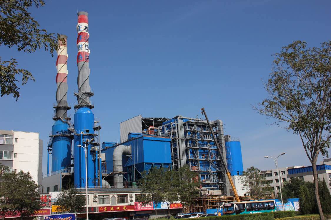
Wade Zhang

CEO of Taishan Group Taian Boao International Trade Co., Ltd. 30 years experience in Global industrial boiler market,  Over 300 boiler projects experience, including 21+ EPC projects. Projects span 30+ countries & regions, involving industries such as nuclear power, energy & electricity, municipal heating, mining, textiles, tires etc.

How to Optimize Industrial Coal-Fired Boiler Performance for Lower Operating Costs Read More »

How to Optimize Industrial Gas-Fired Boiler Performance for Lower Operating Costs

How to Optimize Industrial Gas-Fired Boiler Performance for Lower Operating Costs

Industrial gas-fired boilers are widely used for their high thermal efficiency, cleaner combustion, and ease of control. But even the most advanced systems can become inefficient and costly without proper performance optimization. Poor combustion control, heat losses, and inconsistent maintenance can lead to excessive fuel consumption, equipment degradation, and unnecessary operating expenses. Optimizing your gas-fired boiler ensures maximum return on investment and long-term operational stability.

To optimize industrial gas-fired boiler performance for lower operating costs, focus on combustion tuning, proper air-to-fuel ratio control, flue gas heat recovery, regular maintenance of heat exchange surfaces, and integration of smart monitoring systems. Efficiency improvements can be achieved by reducing excess air, maintaining clean burners and economizers, and adjusting load management strategies. Incorporating real-time analytics and preventive diagnostics can help minimize downtime, extend equipment life, and reduce fuel waste.

Let’s break down the key strategies for driving better efficiency and lowering your boiler’s operating costs.

How Does Burner Tuning and Air-Fuel Ratio Optimization Reduce Fuel Consumption?

In industrial boilers, fuel costs can account for over 70% of total operating expenses. Any deviation in combustion balance—even by a few percentage points—can lead to significant energy losses and excess emissions. One of the most effective ways to minimize fuel consumption without compromising performance is through precise burner tuning and air-fuel ratio optimization. Burners that are out of alignment, clogged, or poorly adjusted waste fuel through incomplete combustion or excessive excess air. When air-fuel control is calibrated properly, combustion becomes more efficient, releasing maximum energy per unit of fuel and reducing wasteful heat losses.

Burner tuning and air-fuel ratio optimization reduce fuel consumption by ensuring that fuel burns completely and efficiently with just the right amount of air. Proper tuning aligns burner settings, damper positions, and flame patterns to maximize heat release while minimizing unburned fuel and excess air. Too little air causes incomplete combustion and CO emissions, while too much air cools the flame and increases stack losses. Optimizing the air-fuel ratio improves flame stability, lowers flue gas temperature, and increases heat transfer efficiency—leading to measurable fuel savings.

In boiler combustion, precision isn’t optional—it’s profitable.

Optimized air-fuel ratio through burner tuning reduces fuel consumption by maximizing combustion efficiency.True

Precise control avoids incomplete combustion and minimizes heat losses due to excess air.


🔍 What Is Burner Tuning?

Tuning ActivityPurpose
Burner AlignmentEnsures uniform fuel distribution across flame
Damper AdjustmentControls primary and secondary air mixing
Fuel Nozzle Inspection/CleaningMaintains proper spray and atomization
Ignition and Flame Stability ChecksPrevents flameout, CO spikes
Control Loop CalibrationEnsures sensors (O₂, temp, CO) provide accurate feedback

→ Tuning is about matching combustion conditions to design performance.


📏 Understanding Air-Fuel Ratio Optimization

TermDescription
Stoichiometric RatioExact air required for complete combustion of the fuel
Excess AirAir supplied above stoichiometric level to ensure full burnout
O₂ in Flue Gas (%)Key indicator of excess air—optimal range: 3–5% for most fuels
ConditionO₂ (%)CO (ppm)Fuel Use Impact
Too Little Air<2>300Incomplete burn → waste ↑
Optimal Air-Fuel Ratio3–4.5<100✅ Maximum efficiency
Too Much Air>6<50Stack losses ↑ → fuel ↑

→ Air-fuel optimization is about finding and maintaining that sweet spot.


📊 Impact of Air-Fuel Ratio on Fuel Consumption

O₂ in Flue Gas (%)Flue Gas Temp (°C)Efficiency (%)Fuel Use (kg/hr)Fuel Savings Potential
7.025578.56,500
4.519586.35,800✅ ~700 kg/hr saved
2.018083.05,900⚠ CO ↑ (incomplete burn)

→ Proper tuning saves fuel while maintaining safe and stable combustion.


🧪 Case Study – Gas-Fired Boiler Burner Tuning

  • System: 20 TPH natural gas boiler

  • Initial Readings:

    • O₂ = 6.8%, Flue gas temp = 240°C, CO = 45 ppm

    • Thermal efficiency = 80.1%, Fuel usage = 4,200 Nm³/hr

  • Action:

    • Recalibrated O₂ sensors

    • Adjusted air dampers to reduce excess air

    • Retuned burner flame shape and mixing

  • Post-Tuning Results:

    • O₂ = 3.9%, Flue gas temp = 185°C

    • Efficiency = 88.2%, Fuel usage = 3,750 Nm³/hr

    • Fuel savings = ~450 Nm³/hr (~10.7% reduction)

Better combustion = less gas burned per ton of steam.


🔧 Tools and Instruments for Tuning and Optimization

Instrument / SystemFunction
Flue Gas Analyzer (O₂, CO, NOx)Measures combustion quality
Thermocouples / RTDsMonitor flame and flue gas temperatures
SCADA with Real-Time Tuning DashboardTracks efficiency, recommends adjustments
Damper Position IndicatorsVisualize air flow changes
Auto O₂ Trim Control SystemContinuously adjusts excess air automatically

→ Tuning is most effective when paired with real-time combustion feedback.


🛠 Best Practices for Burner Tuning and Air-Fuel Control

PracticeBenefit
Schedule seasonal tuningAccounts for temperature/humidity impact
Clean nozzles and diffusers regularlyMaintains consistent fuel spray and mixing
Log and trend O₂/CO/efficiency dataIdentifies drift or degradation
Calibrate sensors quarterlyPrevents errors in air-fuel feedback loops
Perform burner visual inspectionsDetects flame instability and maldistribution

→ Fuel economy is not just in the fuel—it’s in the settings and sensors.


📈 Annual Fuel Savings from Burner Optimization

Boiler Size (TPH)Fuel TypePre-Tuning EfficiencyPost-TuningAnnual Savings
15 TPHBiomass72.4%82.0%~1,200 tons
20 TPHNatural Gas79.6%88.1%~95,000 Nm³
40 TPHCoal76.2%85.3%~4,500 tons

→ Burner tuning is often the fastest ROI in boiler optimization.


In conclusion, burner tuning and air-fuel ratio optimization are cornerstone practices for reducing fuel consumption and maximizing boiler efficiency. By ensuring that combustion is complete and air is supplied in just the right amount, operators can reduce fuel waste, cut emissions, and extend equipment life. These optimizations don’t require massive capital—but they deliver massive impact. In thermal systems, the best savings come not from burning harder—but burning smarter.

Why Is Flue Gas Heat Recovery Critical for Maximizing Thermal Efficiency?

In every boiler system—regardless of fuel type—a significant amount of heat escapes through the flue gas. Even in well-tuned combustion systems, stack temperatures can exceed 180–250°C. This heat represents unrecovered energy that was paid for but never used. The higher the flue gas temperature, the greater the potential for energy loss—and the larger the opportunity for savings. Flue gas heat recovery systems like economizers, air preheaters, and condensing heat exchangers capture this otherwise wasted energy and redirect it back into the system. This process dramatically improves thermal efficiency, reduces fuel consumption, and lowers emissions.

Flue gas heat recovery is critical for maximizing thermal efficiency because it captures residual heat from exhaust gases and transfers it to feedwater, combustion air, or process fluids. This reduces the energy needed to raise steam, preheat air, or warm water, thereby decreasing fuel use and increasing boiler efficiency. Without recovery, this heat escapes through the stack, resulting in higher operating costs and lost energy. Installing economizers or condensing systems can improve thermal efficiency by 5–15%, making it one of the most impactful efficiency upgrades in any boiler system.

In a boiler, flue gas is not just waste—it’s a second chance to save energy.

Flue gas heat recovery significantly boosts thermal efficiency by reclaiming heat that would otherwise be lost through the stack.True

This recovered energy reduces the fuel needed to heat feedwater or combustion air, improving overall system efficiency.


🔍 How Flue Gas Heat Recovery Works

ComponentFunction
EconomizerTransfers flue gas heat to incoming feedwater
Air Preheater (APH)Preheats combustion air using exhaust heat
Condensing Heat ExchangerCaptures latent heat from water vapor in flue gas
Heat Pipe / RecuperatorTransfers heat to process streams or district heating

→ These systems lower flue gas temperature and redirect energy back into the cycle.


📏 Typical Flue Gas Temperatures and Recovery Potential

System TypeExit Flue Gas Temp (°C)Recovery MethodEstimated Efficiency Gain (%)
Standard Boiler220–260Economizer4–7
CFB or Biomass Boiler180–220Economizer + APH6–9
Gas-Fired Condensing60–90Condensing heat exchanger8–15
Coal-Fired Utility150–200Economizer + APH + Sootblowers5–10

→ Every 10°C reduction in flue gas temperature recovers up to 1% of fuel energy.


📊 Example: Heat Recovery from Flue Gas

ParameterBefore RecoveryAfter Recovery
Flue Gas Temperature (°C)245170
Feedwater Temp (°C)90140
Boiler Efficiency (%)79.587.2
Fuel Consumption (kg/hr)6,5005,720
Efficiency Gain+7.7%

→ Economizer installation reduced flue gas temperature by 75°C and saved 780 kg/hr of fuel.


🧪 Case Study – Biomass Boiler with Economizer Upgrade

  • System: 15 TPH biomass boiler, stack temp 230°C

  • Intervention: Installed finned-tube economizer on flue duct

  • Result:

    • Flue temp reduced to 155°C

    • Feedwater temp raised from 85°C to 132°C

    • Efficiency improved from 74.2% to 82.9%

    • Annual fuel savings: ~1,100 tons

→ ROI achieved in less than 18 months.


📈 Benefits of Flue Gas Heat Recovery

BenefitExplanation
Increased Boiler EfficiencyMore energy extracted from the same fuel
Reduced Fuel ConsumptionLess fuel needed to reach desired steam temp
Lower CO₂ and NOx EmissionsLower combustion volume reduces emissions per MWh
Improved Steam Output StabilityPreheated water leads to smoother operation
Reduced Boiler LoadSystem runs closer to design setpoint

→ Heat recovery transforms efficiency from a theoretical concept into real savings.


🔧 Key Factors in Heat Recovery Design

FactorWhy It Matters
Flue Gas CompositionMoisture and acid gases affect corrosion risk
Soot and Fouling BehaviorImpacts cleaning frequency and recovery consistency
Material SelectionStainless steel or alloy for acidic condensates
Maintenance AccessEasy access for soot blowing and tube inspection
Space ConstraintsDetermines whether economizer or condensing system

→ Engineering heat recovery systems requires balance between efficiency and durability.


🛠 Maintenance and Monitoring for Recovery Systems

TaskFrequencyBenefit
Tube Cleaning (Sootblowing)Weekly to monthlyPrevents insulation of surfaces
Flue Gas Temp LoggingContinuousTracks performance drop-off
Corrosion InspectionQuarterlyAvoids tube failure in condensing zones
Drain System Check (Condensers)MonthlyEnsures water and acid are safely removed
Water Quality MonitoringOngoingPrevents scaling on feedwater side

→ Even efficient recovery systems require care to stay efficient.


In conclusion, flue gas heat recovery is one of the most effective and accessible ways to enhance thermal efficiency in industrial boiler systems. By reclaiming energy that would otherwise be lost, it reduces fuel consumption, lowers emissions, and improves system performance. Whether through an economizer, air preheater, or condensing exchanger, heat recovery transforms exhaust into value. In thermal systems, what you recover is just as important as what you burn.

What Role Does Regular Maintenance Play in Maintaining High-Performance Operation?

Industrial boilers, power plant systems, and heat exchangers are designed for high performance—but over time, performance inevitably degrades without regular maintenance. Fouling, scale buildup, drift in sensors, air leaks, and mechanical wear all contribute to declining efficiency, rising emissions, and even dangerous operating conditions. Regular maintenance isn’t just about fixing what’s broken—it’s about preserving the finely balanced conditions needed for efficient combustion, heat transfer, and system integrity. Neglecting this leads to energy loss, equipment failure, and increased operating costs. Proactive maintenance is therefore essential to ensure safe, efficient, and reliable performance across the system’s lifespan.

Regular maintenance plays a critical role in sustaining high-performance operation by preventing the accumulation of efficiency losses, ensuring optimal heat transfer, maintaining accurate sensor readings, and preserving mechanical integrity. Routine tasks such as cleaning heat exchanger surfaces, calibrating instruments, checking seals, and tuning combustion systems ensure the boiler operates at peak efficiency, consumes less fuel, and emits fewer pollutants. Without maintenance, even the best-designed systems experience rapid degradation in output and reliability.

Maintenance is not a cost—it’s a strategic investment in continuous performance.

Regular maintenance is essential for sustaining high-performance operation in boilers and thermal systems.True

It prevents gradual degradation from fouling, drift, wear, and corrosion, all of which reduce efficiency and reliability.


🔍 Why Maintenance Is a Pillar of Performance

Maintenance ObjectiveEfficiency Benefit
Remove Fouling from SurfacesRestores heat transfer → reduces fuel usage
Calibrate SensorsEnsures correct combustion and steam control
Inspect and Clean BurnersMaintains flame stability and complete combustion
Check for Steam and Air LeaksPrevents invisible heat and pressure loss
Service Pumps and ValvesEnsures stable feedwater and fuel delivery

→ Each task helps maintain the fine balance of thermal efficiency.


📏 Key Performance Areas Affected by Maintenance

System ComponentMaintenance ActionPerformance Risk if Ignored
Economizer / SuperheaterSoot blowing and cleaningHigh flue gas temp, low steam output
Burner SystemInspection, tuning, alignmentCO emissions, fuel waste, unstable flame
O₂ / CO AnalyzersSensor calibrationIncorrect air-fuel ratio, efficiency ↓
Feedwater SystemDescaling, valve checksBoiler scaling, pressure control issues
Insulation & SealsInspection and repairRadiation loss, temperature instability

→ A single overlooked issue can degrade multiple efficiency parameters.


📊 Efficiency Loss Trends Without Maintenance

Maintenance LapseTypical Time to DegradationEfficiency Loss (%)
Soot Accumulation1–3 weeks3–10
Sensor Drift (O₂)1–2 months2–5
Scaling in Water Side2–6 months1–4
Leaking Steam Traps3–6 months2–8
Air Duct LeaksGradual1–6

→ Small issues accumulate quickly without scheduled intervention.


🧪 Case Study – Maintenance-Driven Efficiency Recovery

  • System: 25 TPH coal-fired boiler

  • Problem: Thermal efficiency dropped from 84% to 76% over six months

  • Findings:

    • Economizer fouled (flue gas temp increased by 40°C)

    • O₂ sensor was off by 1.2% (reading too low)

    • Air leaks around burner assembly

  • Maintenance Action:

    • Cleaned economizer tubes

    • Recalibrated sensors and checked dampers

    • Sealed air leaks and retuned burners

  • Result:

    • Efficiency restored to 85.1%

    • Fuel savings of ~1,600 tons/year

    • ROI on maintenance costs achieved in 4 months

Maintenance turned a declining system back into a high-performance unit.


🔧 Recommended Maintenance Schedule for High Efficiency

TaskFrequencyBenefit
Soot Blowing / Tube CleaningDaily to weeklyKeeps heat surfaces clean
Burner Inspection and TuningMonthly to quarterlyMaintains combustion quality
Sensor Calibration (O₂, CO, Temp)MonthlyEnables accurate air-fuel control
Leak Detection and RepairMonthlyPrevents energy and pressure loss
Water Treatment System CheckWeeklyPrevents scale and corrosion
Boiler Blowdown ManagementDaily or automatedControls TDS, improves heat exchange

→ Following a schedule ensures issues are resolved before they cost energy.


📈 Benefits of Regular Maintenance for Performance & Cost

BenefitHow Maintenance Delivers It
Higher Thermal EfficiencyClean surfaces, tuned combustion, accurate sensors
Lower Fuel ConsumptionReduced stack loss, better heat recovery
Stable Steam OutputPrevents interruptions from scaling, fouling
Longer Equipment LifespanAvoids stress from hot spots, corrosion
Reduced Downtime and OutagesCatches failures before escalation

→ Maintenance is the foundation of operational excellence.


🛠 Maintenance Best Practices for Maximum Efficiency

Best PracticeWhy It Matters
Digital Maintenance LogsTrack trends, predict wear, schedule service
Thermal Imaging InspectionsIdentify insulation failures and heat leaks
Condition-Based CleaningUse temperature or ΔP data to trigger cleaning
Training Maintenance PersonnelEnsures proper techniques and faster resolution
Integrated Efficiency MonitoringLinks performance KPIs to maintenance strategy

→ Efficiency gains are realized when maintenance is strategic—not reactive.


In conclusion, regular maintenance is the backbone of high-performance boiler operation. It ensures that combustion, heat transfer, and control systems remain aligned, clean, and optimized. Without it, performance steadily deteriorates—driving up fuel use, emissions, and operating costs. A well-maintained system, however, performs closer to design capacity, consumes less energy, and runs more reliably. In thermal energy systems, maintenance isn’t just support—it’s an essential driver of efficiency and sustainability.

How Can Real-Time Monitoring and Boiler Automation Reduce Operational Costs?

In industrial boiler systems, energy, labor, and maintenance constitute the largest operational costs. Traditional manual monitoring methods—while still used—are often reactive, delayed, and prone to human error. As fuel prices rise and emissions limits tighten, real-time monitoring and automation have become essential tools for cost-conscious, efficiency-driven operations. These technologies transform boilers from passive systems into intelligent, self-optimizing assets, capable of adjusting to load changes, detecting anomalies, and reducing unnecessary energy consumption—all without manual intervention.

Real-time monitoring and boiler automation reduce operational costs by continuously tracking key performance indicators such as flue gas composition, fuel flow, steam output, and temperature, then automatically adjusting combustion parameters, load profiles, and cleaning schedules to maintain optimal efficiency. This prevents energy waste, reduces fuel consumption, minimizes emissions penalties, and avoids costly maintenance caused by undetected faults. Automated systems also reduce labor dependency and downtime, leading to measurable cost savings across fuel, maintenance, and compliance.

Smart boilers don’t just operate—they think, optimize, and save.

Real-time monitoring and boiler automation help reduce operational costs by maintaining optimal combustion, preventing faults, and minimizing energy waste.True

Automation continuously adjusts air-fuel ratios and load response, while real-time sensors detect issues early, cutting fuel and maintenance expenses.


🔍 Core Functions of Boiler Monitoring and Automation Systems

FeaturePurpose
Real-Time Sensor DataTracks O₂, CO, flue gas temp, steam flow, fuel input
Combustion Control (O₂ Trim)Adjusts dampers and burners to optimize air-fuel ratio
Automatic Load ManagementMatches fuel firing rate to steam demand
Alarm & Fault DetectionIdentifies leaks, pressure drops, scaling, and combustion drift
Automated Cleaning (Sootblowing)Triggers based on pressure drop or temperature thresholds

→ These functions enable the boiler to self-optimize and prevent inefficiencies.


📊 Impact of Real-Time Monitoring on Cost Reduction

Performance MetricWithout AutomationWith AutomationSavings Impact
Thermal Efficiency (%)75–8085–89Fuel use ↓ 5–15%
O₂ Variability (±%)±2.5±0.5Air control improves
Steam Output StabilityFluctuatesSmooth and responsiveLoad handling ↑
Downtime per Year (hrs)80–120<30Maintenance cost ↓
CO/NOx ComplianceReactiveProactive, real-timeEmissions penalty ↓

→ A well-automated system pays for itself in less than 2 years in most plants.


🧪 Case Study – Automation Upgrade in a 40 TPH Coal Boiler

  • Problem: Unstable steam output, O₂ drift, high CO (avg 180 ppm)

  • Manual Operation:

    • Efficiency ~78.5%, flue gas temp = 240°C

    • Operators adjusted dampers every 2 hours

  • Intervention:

    • Installed SCADA + PLC-based automation

    • Added real-time O₂, CO, temp sensors

    • Auto-tuned burners and sootblowers

  • Results (Post Upgrade):

    • Efficiency = 86.4%, flue gas temp = 185°C

    • CO = 55 ppm, O₂ maintained at 3.9%

    • Fuel savings = ~3,400 tons/year

    • Unplanned downtime ↓ by 70%

→ Automation enabled continuous efficiency—not just occasional optimization.


📈 Operational Cost Savings from Monitoring & Automation

Cost AreaPre-Automation (Annual)Post-Automation (Annual)Reduction (%)
Fuel Costs$1,200,000$1,035,00013.75%
Maintenance Labor$150,000$105,00030%
Downtime Losses$90,000$22,00075.5%
Emissions Fines$18,000$0100%

→ Combined savings: over $295,000/year from real-time monitoring investment.


🔧 Technologies That Enable Smart Boiler Operation

System or DeviceRole in Cost Savings
SCADA / HMI DashboardsCentralized control and data logging
PLC-Based Combustion ControlExecutes air-fuel adjustments based on real-time data
O₂ / CO / NOx SensorsInput for combustion optimization and emissions tracking
Steam Flow and Pressure SensorsAdjust fuel and feedwater in real-time
Smart Sootblowers (On-Demand)Clean only when needed → avoids energy waste

→ When connected, these components form an intelligent feedback loop.


🛠 Best Practices for Implementing Monitoring and Automation

PracticeBenefit
Calibrate Sensors RegularlyEnsures data accuracy and reliability
Train Operators on Digital ToolsPromotes better use and trust in automation
Integrate Energy KPIs into DashboardsMakes performance goals visible and actionable
Set Alarms for Efficiency DropEnables fast response to issues
Benchmark Before vs. After DataJustifies ROI and guides further improvements

→ Smart systems still require smart oversight and disciplined use.


In conclusion, real-time monitoring and boiler automation are powerful enablers of cost reduction in thermal systems. They convert traditional reactive operations into proactive, intelligent processes that conserve fuel, stabilize output, and avoid costly failures. With automated control of combustion, sootblowing, load response, and emissions, plants achieve greater efficiency with fewer resources. In the future of energy management, automation isn’t a luxury—it’s the engine of profitability.

How Does Proper Load Management Prevent Cycling Losses and Inefficiency?

Boilers are most efficient when operating at or near steady-state conditions. However, many facilities experience frequent load changes due to variable process demands, poor scheduling, or undersized system components. This causes cycling—frequent starts, stops, or sharp modulation shifts—which leads to thermal stress, fuel waste, and higher emissions. Every time a boiler ramps up or shuts down, it consumes extra fuel for purging, preheating, and stabilization. Proper load management avoids these losses by matching boiler operation to demand in a planned and predictive way, maximizing uptime and minimizing energy waste.

Proper load management prevents cycling losses and inefficiency by maintaining stable boiler operation at optimal firing ranges, avoiding frequent startups, shutdowns, and rapid load swings. It achieves this by balancing process demand, using modulating burners, employing thermal storage, and integrating multiple boilers intelligently. These strategies reduce heat-up losses, eliminate purge-cycle fuel waste, and enhance overall thermal efficiency—especially in systems with variable steam loads. Fewer cycles also extend equipment life and reduce maintenance costs.

In steam systems, it’s not just how much you produce—it’s how consistently you produce it.

Proper load management minimizes cycling losses by keeping boiler operation stable and within efficient firing ranges.True

Reduced cycling lowers purge losses, thermal stress, and inefficient fuel usage during frequent ramp-ups or shutdowns.


🔍 What Are Cycling Losses and Why Do They Happen?

Cycling EventDescriptionEnergy Loss Mechanism
Startup / ShutdownBoiler brought from cold or warm state to firingPurge losses, preheat energy wasted
Rapid Load FluctuationsSudden demand changes requiring burner modulationInefficient combustion at low turndown ratios
Short-CyclingBoiler turns on/off too frequentlyRepeated ignition and purge fuel waste
Thermal Soak / CooldownResidual heat lost after shutdownEnergy not recovered or reused

→ Each cycle consumes energy with no useful output during ramp periods.


📏 Efficiency vs. Load Profile – The Cycling Tradeoff

Load ConditionCycle FrequencyEfficiency (%)Fuel Use Impact
Steady Full LoadLow87–90✅ Optimal
Modulated Partial LoadModerate82–86⚠ Acceptable
Frequent CyclingHigh70–78❌ Increased fuel use
Short-Cycle ModeVery High<70❌ Significant waste

→ Stable operation at 60–100% load yields highest thermal efficiency.


🧪 Case Study – Load Management in a Multi-Boiler System

  • System: Three 15 TPH gas-fired boilers (1 primary, 2 standby)

  • Issue: One boiler cycled on/off 14 times/day due to unbalanced demand

  • Problems Identified:

    • Poor load prediction

    • No load-sharing logic

    • No thermal buffer

  • Solution:

    • Implemented SCADA-based demand forecasting

    • Activated staggered load sharing

    • Installed condensate recovery tank as thermal buffer

  • Results:

    • Startup cycles reduced by 85%

    • Steam pressure stabilized (±0.3 bar)

    • Efficiency improved from 78.2% → 86.7%

    • Annual fuel savings: ~105,000 Nm³

Smarter load scheduling = less fuel burned = more consistent output.


📈 Common Causes of Load-Induced Inefficiency

CauseInefficiency Mechanism
Manual Boiler SequencingNon-optimized boiler activation
Oversized Boilers for Small LoadsLong idle times, poor turndown ratios
No Buffer StorageBoiler must cycle to meet instantaneous load
Unpredictable Demand SurgesForces fast ramping and heat-up cycles
Inadequate Burner ModulationCannot match partial load efficiently

→ These result in more cycles, more purge losses, and higher fuel bills.


🔧 Load Management Strategies to Minimize Cycling

StrategyHow It Helps
Use Modulating BurnersAllows smooth load tracking instead of frequent on/off
Install Boiler Sequencing ControlsActivates boilers based on efficiency/load thresholds
Add Thermal Storage (Accumulator)Absorbs demand spikes without cycling the boiler
Forecast Load PatternsEnables preemptive boiler staging
Operate in Sweet Spot RangeRun boilers at 65–90% load for best performance

→ Predictable load = predictable performance.


🛠 Technologies That Enable Load Optimization

Tool / SystemFunction
SCADA with Load ForecastingUses process data to predict steam demand
Boiler Master ControllersAutomate startup, sequencing, and turndown control
Condensate Recovery SystemRecycles heat, buffers return loads
Smart Burner Management SystemsOptimizes air-fuel ratio across load ranges
Thermal Accumulators / TanksAbsorb excess steam or store hot water

→ Integrated systems ensure boilers respond efficiently—not reactively.


📊 Efficiency Gains from Load Management Optimization

Load Profile ImprovementEfficiency Gain (%)Fuel Savings (%)
Reduce daily cycles by 80%+5.5%~6–10%
Modulate vs. on-off control+3–6%~4–7%
Add thermal storage (accumulator)+4–8%~5–10%
Sequenced multi-boiler control+5–9%~6–12%

→ The more dynamic your demand, the more critical load management becomes.


In conclusion, proper load management is essential for preventing cycling losses and maintaining boiler efficiency. By smoothing demand, modulating operation, and intelligently sequencing equipment, plants can reduce fuel waste, improve steam quality, and extend boiler life. With smart planning and the right tools, load becomes a controlled input—not a cause of inefficiency. In thermal systems, the best energy isn’t just clean—it’s consistently delivered.

What Fuel Quality and Gas Pressure Parameters Should Be Monitored Consistently?

In gas-fired industrial boilers, consistent combustion performance and thermal efficiency depend on stable fuel quality and regulated fuel delivery pressure. Yet, these parameters are often taken for granted—leading to unnoticed inefficiencies, flame instability, and equipment wear. Even minor fluctuations in gas composition or pressure can cause combustion drift, CO formation, or temperature swings, directly impacting energy costs and emissions. To maintain optimal boiler performance, real-time monitoring of fuel quality and gas pressure is essential for both operational control and long-term reliability.

The fuel quality and gas pressure parameters that should be consistently monitored include calorific value (CV), gas composition (especially methane content), Wobbe Index, moisture, sulfur or contaminants, delivery pressure, and pressure stability. These metrics ensure consistent combustion heat input, flame stability, and air-fuel ratio control. Monitoring gas pressure prevents under- or over-firing, while fuel quality data supports real-time combustion adjustments. Together, they help maintain boiler efficiency, prevent damage, and ensure compliance with safety and emissions standards.

When it comes to combustion, you can’t control what you don’t measure—especially your fuel.

Consistent monitoring of gas quality and pressure is essential for stable and efficient combustion in industrial boilers.True

Fuel variability and pressure fluctuations can lead to incomplete combustion, flame instability, and energy losses.


🔍 Key Fuel Quality Parameters to Monitor

ParameterDescriptionWhy It Matters
Calorific Value (CV)Heat energy per unit volume (e.g., MJ/Nm³)Directly affects combustion heat release and efficiency
Methane Content (%)Proportion of CH₄ in natural gasHigh methane = predictable flame and CV
Wobbe Index (MJ/m³)CV adjusted for gas densityDetermines interchangeability and burner performance
Moisture ContentWater vapor in gasReduces CV and promotes corrosion
Sulfur (H₂S) & ContaminantsReactive elements that corrode componentsAffects emissions, causes acid dewpoint corrosion
Particulate/Condensate PresenceDust or liquids in gas streamBlocks nozzles, erodes burners

→ Changes in fuel chemistry affect flame shape, temperature, and emissions.


📏 Ideal Gas Quality Ranges for Stable Combustion

ParameterIdeal Range (Natural Gas)Notes
Calorific Value35–39 MJ/Nm³Stable output and flame characteristics
Methane Content≥ 85%High methane ensures predictable CV
Wobbe Index48–52 MJ/Nm³Must match burner design range
Moisture< 1 g/Nm³Excess causes condensate, derates CV
H₂S Content< 5 ppm (typically)Higher values require treatment

→ Fuel deviation from these ranges requires combustion system recalibration.


🔧 Gas Pressure Parameters That Must Be Monitored

ParameterDescriptionRisk if Unmonitored
Inlet Gas PressurePressure entering the burner trainToo low = flame instability; too high = damage risk
Regulated Set PressurePost-pressure-regulator value (e.g., 250 mbar)Ensures safe and consistent firing
Pressure Stability (ΔP)Variation in gas pressure during operationInstability leads to combustion drift
Minimum Operating PressureManufacturer-specified minimum for burner ignitionBelow = flame failure, lockout
Overpressure Trip SettingsSafety control to prevent over-firingPrevents equipment damage and explosion

→ Gas pressure swings must be minimized to keep the combustion system balanced.


🧪 Case Study – Pressure & Quality Monitoring in a Gas-Fired Plant

  • System: 30 TPH industrial gas boiler

  • Symptoms: Flame instability during peak shifts, CO spikes > 200 ppm

  • Findings:

    • Inlet gas pressure fluctuated between 170–280 mbar (target = 250)

    • Wobbe Index dropped to 45 MJ/Nm³ due to supplier blending

    • Air-fuel ratio stayed constant → under-combustion during low CV events

  • Action Taken:

    • Installed automated gas quality analyzer (Wobbe Index + CV)

    • Added mass flow control valve and pressure stabilizer

    • Linked analyzer output to O₂ trim control system

  • Result:

    • Flue gas O₂ stabilized at 4.2%, CO < 60 ppm

    • Efficiency improved from 81.4% to 88.0%

    • Fuel use decreased by ~8.5%

Real-time data closed the loop between fuel variability and combustion response.


📊 Real-Time Monitoring Benefits

Metric MonitoredAction EnabledEfficiency or Cost Benefit
Calorific ValueAdjust fuel-air ratio on the flyPrevents energy imbalance
Gas PressureMaintain flame integrity and modulator rangeAvoids low-efficiency firing or flameout
Wobbe IndexPredicts burner performanceEnsures stable output across fuel blends
Moisture/H₂S SensorsTrigger alarms or filtration systemsProtects heat exchangers and burners

→ Proper monitoring leads to better combustion control and longer equipment life.


🛠 Recommended Instruments for Fuel & Pressure Monitoring

InstrumentMeasurementFrequency
Calorimeter / Wobbe AnalyzerCV, Wobbe IndexContinuous
Gas Chromatograph (Optional)Full gas composition (CH₄, CO₂, H₂S)Periodic/lab
Inline Gas Moisture MeterMoisture (g/Nm³)Continuous
Pressure Transducers / GaugesInlet and outlet gas pressuresContinuous
Differential Pressure SensorsΔP across regulators or filtersContinuous

→ Continuous sensors can be integrated into SCADA or burner management systems.


📈 Operational Consequences of Not Monitoring Fuel and Pressure

OversightConsequenceCost Impact
Gas CV Drop UndetectedLean flame, CO ↑, reduced steam outputFuel waste, penalties
Pressure Swings IgnoredFlame instability, safety shutdownsDowntime, reliability ↓
High Moisture ContentLower CV, corrosion riskMaintenance, boiler wear
Undetected H₂S PeaksTube corrosion, acid dewpointHeat exchanger failure

→ Monitoring avoids hidden performance killers.


In conclusion, consistent monitoring of fuel quality and gas pressure is essential to maintain combustion efficiency, operational stability, and equipment safety in industrial boilers. Without it, plants are exposed to fuel waste, CO emissions, and safety risks. With real-time monitoring and intelligent control, boilers adapt to fuel variability, maintain efficient combustion, and reduce lifecycle costs. In thermal systems, monitoring your fuel is managing your future.

🔍 Conclusion

Lowering the operating costs of an industrial gas-fired boiler is not about one-time fixes—it’s about continuous optimization through data, maintenance, and smart control. By fine-tuning combustion, recovering waste heat, and proactively managing performance, companies can significantly reduce fuel use, emissions, and downtime. A well-optimized gas boiler is not only more cost-effective but also more compliant, reliable, and future-ready.


📞 Contact Us

💡 Need help optimizing your gas-fired boiler system? Our team provides combustion tuning, energy audits, automation integration, and maintenance planning for industrial gas boilers of all capacities.

🔹 Contact us today and start saving fuel, reducing costs, and maximizing boiler performance! 🔥📉✅

FAQ

What are the key strategies to optimize gas-fired boiler performance?

Optimization involves a combination of operational, mechanical, and control upgrades:

  • Regular combustion tuning and flue gas analysis

  • Proper burner and flame adjustment

  • Installation of oxygen trim controls

  • Use of economizers for heat recovery

  • Routine maintenance of heat exchanger surfaces and valves

How can combustion control systems reduce fuel consumption?

Advanced combustion controls (such as O₂ trim systems and parallel positioning) adjust fuel and air input in real time, maintaining optimal air-to-fuel ratios. This reduces excess air, improves combustion efficiency, and lowers gas usage by 5–10%.

What role do economizers play in energy savings?

Economizers recover heat from exhaust flue gases to preheat feedwater. This process improves boiler efficiency by 3–7% and lowers the fuel demand needed to generate steam or hot water.

Why is preventative maintenance important for cost optimization?

Routine cleaning of burners, heat exchanger tubes, and flue pathways prevents fouling, which can decrease heat transfer efficiency. Replacing worn-out gaskets, seals, and valves ensures stable operation and reduces unplanned downtime.

Can boiler modulation improve efficiency and reduce operating costs?

Yes. A modulating burner system adjusts fuel and air flow according to real-time steam or heat demand, avoiding inefficient on-off cycling. This leads to longer component life, consistent combustion, and significant fuel savings.

References

  1. Boiler Energy Efficiency Improvement Guidehttps://www.energy.gov

  2. Combustion Optimization Techniqueshttps://www.sciencedirect.com

  3. Industrial Boiler Controls and Automationhttps://www.automation.com

  4. Oxygen Trim and Burner Management Systemshttps://www.researchgate.net

  5. Economizer Retrofit Case Studieshttps://www.bioenergyconsult.com

  6. Gas Boiler Efficiency Trends and Maintenancehttps://www.mdpi.com

  7. Preventative Maintenance for Industrial Boilershttps://www.epa.gov

  8. Energy Cost Reduction in Steam Systemshttps://www.iea.org

  9. Boiler Tuning and Flue Gas Analysishttps://www.energysavingtrust.org.uk

  10. Smart Controls for Industrial Boilershttps://www.asme.org
Wade Zhang

CEO of Taishan Group Taian Boao International Trade Co., Ltd. 30 years experience in Global industrial boiler market,  Over 300 boiler projects experience, including 21+ EPC projects. Projects span 30+ countries & regions, involving industries such as nuclear power, energy & electricity, municipal heating, mining, textiles, tires etc.

How to Optimize Industrial Gas-Fired Boiler Performance for Lower Operating Costs Read More »

Key Factors Influencing Heat Transfer and Combustion Efficiency in Circulating Fluidized Bed Boilers

Key Factors Influencing Heat Transfer and Combustion Efficiency in Circulating Fluidized Bed Boilers

Circulating Fluidized Bed (CFB) boilers are well-known for their fuel flexibility, low emissions, and stable combustion—but achieving high heat transfer and combustion efficiency in these systems depends on a complex interaction of fuel properties, operational settings, and boiler design. If not properly managed, these variables can lead to reduced thermal output, fuel waste, ash-related issues, and increased emissions. Understanding these influencing factors is essential for optimizing system performance and reliability.

In CFB boilers, heat transfer and combustion efficiency are influenced by factors such as particle size distribution, bed temperature, excess air ratio, fuel reactivity, circulation rate, ash behavior, and heat exchanger surface condition. Unlike conventional boilers, CFBs rely on fluidized mixing of fuel and inert material to promote uniform combustion and efficient heat distribution. Therefore, precise control of fluidization dynamics, fuel feed rate, and temperature zones is essential for achieving maximum combustion efficiency and effective heat recovery.

Let’s explore the critical technical variables that impact efficiency in a CFB boiler system.

How Does Bed Temperature Affect Combustion Stability and Heat Release in CFB Boilers?

Circulating Fluidized Bed (CFB) boilers are valued for their fuel flexibility and low emissions. However, their performance depends critically on maintaining the correct bed temperature, which governs the combustion reactions, fluidization dynamics, and pollutant formation. If bed temperature drops too low, combustion becomes unstable and incomplete, leading to unburned carbon, CO emissions, and reduced steam generation. On the other hand, excessive bed temperatures can cause agglomeration of bed material, refractory damage, and even system trips. For stable, efficient, and clean operation, the bed temperature must be carefully controlled within an optimal range.

Bed temperature in a CFB boiler directly influences combustion stability and heat release by determining the rate and completeness of fuel burnout. If the bed is too cold, combustion is incomplete, leading to poor ignition, higher CO, and reduced thermal output. If it’s too hot, sintering and agglomeration of the bed particles can occur, disrupting fluidization. An optimal bed temperature—typically between 820°C and 890°C—ensures steady combustion, efficient heat release, and minimal emissions.

In CFB systems, the bed is not just where combustion occurs—it’s where combustion is controlled.

Bed temperature in a CFB boiler directly affects combustion efficiency, stability, and system reliability.True

Correct temperature ensures complete fuel burnout and avoids bed agglomeration or unburned carbon losses.


🔍 The Role of Bed Temperature in CFB Combustion

FunctionBed Temperature Effect
Ignition and Flame FormationToo low = delayed ignition; too high = unstable flame
Fuel BurnoutModerate bed temp ensures complete carbon combustion
Volatile ReleaseControlled release occurs near 800–850°C
Fluidization StabilityExcess heat causes defluidization and agglomeration
NOx and SO₂ EmissionsOptimal temp reduces thermal NOx and aids SO₂ capture

→ Bed temperature is the governing parameter in combustion chemistry and bed behavior.


📏 Typical Bed Temperature Ranges for Common Fuels

Fuel TypeRecommended Bed Temp (°C)Notes
Bituminous Coal840–880Stable combustion and good ash behavior
Lignite820–850Needs lower temps to avoid slagging
Biomass (wood chips)800–850Higher volatiles, low ash fusion point
Petroleum Coke860–900High CV and sulfur, aggressive fuel
Waste RDF830–870Varies by composition

→ The optimal range ensures efficient heat release without operational risks.


📊 Effects of Bed Temperature Variation on Combustion Output

Bed Temp (°C)Combustion QualityCO Emissions (ppm)Steam Output (TPH)Bed Stability
780Incomplete burn32043.5Stable but underperforming
820Good combustion8549.0Ideal
860Optimal balance4050.2Very stable
910Agglomeration begins6046.8Risk of instability

→ Staying in the 820–870°C range maximizes combustion efficiency.


🛠 Causes and Consequences of Improper Bed Temperatures

ConditionCauseConsequence
Low Bed TemperatureCold fuel, high excess air, wet biomassIncomplete combustion, CO ↑, UBC ↑
High Bed TemperatureOverfeeding, inadequate air stagingAgglomeration, ash fusion, trips
Temperature FluctuationsLoad swings, poor control tuningSteam pressure variation, instability

→ Temperature drift can cause cascading losses in combustion and energy output.


🧪 Case Study – Biomass/Coal Co-Firing in CFB Boiler

  • System: 100 TPH CFB boiler

  • Fuel Mix: 70% bituminous coal, 30% biomass

  • Initial Condition: Bed temp = 795°C → CO = 300 ppm, steam = 91.2 TPH

  • Action: Increased preheated primary air temp and tuned secondary air

  • Optimized Condition: Bed temp = 845°C → CO = 75 ppm, steam = 100.1 TPH

  • Result: Efficiency increased from 81.4% to 87.2%

Temperature control restored stable output and improved combustion quality.


📈 Key Metrics Tied to Bed Temperature

Performance IndicatorHow It Changes With Bed Temperature
CO Emissions↓ when temperature is within ideal range
NOx Emissions↑ if temperature exceeds 900°C
Unburned Carbon in Ash↑ if temperature < 800°C
Heat Rate (kJ/kWh)↓ as combustion becomes more efficient
Steam Pressure FluctuationStabilizes with constant bed temp

→ Bed temperature is a root variable driving all other combustion parameters.


🔧 Best Practices for Maintaining Optimal Bed Temperature

PracticeBenefit
Preheat Primary and Secondary AirIncreases ignition stability
Optimize Fuel Particle SizeEnsures even combustion and temperature
Use Bed Material with Right PropertiesAvoids agglomeration and heat spikes
Install Bed Temperature Sensors at Multiple LevelsEnables accurate control
Implement Bed Cooling/Bypass DuctsControls peak temperature zones

→ Temperature control requires both mechanical and combustion tuning systems.


In conclusion, bed temperature is the central control variable for combustion stability and heat release in CFB boilers. It governs how well the fuel burns, how efficiently heat is transferred, and whether emissions targets are met. Maintaining the temperature within an optimal range ensures stable flame, maximum steam generation, and long-term equipment integrity. In CFB technology, temperature isn’t just a setting—it’s the heartbeat of the entire system.

Why Is Fuel Particle Size and Reactivity Important for Combustion Efficiency?

In solid fuel combustion systems—such as biomass boilers, coal-fired furnaces, or fluidized bed combustors—fuel characteristics define performance. Among these, particle size and fuel reactivity are two of the most critical but often overlooked factors affecting combustion efficiency. Poorly sized fuel leads to uneven burning, unstable flame, unburned residues, and inconsistent steam output. Similarly, low reactivity fuels take longer to ignite and burn out, causing incomplete combustion and higher CO emissions. By contrast, properly sized and reactive fuel burns thoroughly, fast, and uniformly—unlocking the boiler’s full thermal potential.

Fuel particle size and reactivity are crucial for combustion efficiency because they determine how quickly and completely the fuel ignites, burns, and releases energy. Smaller, uniformly sized particles offer higher surface area, promoting faster ignition and better mixing with air, while high-reactivity fuels combust more easily and thoroughly. Oversized or low-reactivity fuels cause delayed ignition, incomplete burnout, CO emissions, and heat losses. Optimizing size and selecting reactive fuels ensures consistent flame, full energy release, and reduced unburned carbon losses.

In combustion, fuel quality isn’t optional—it’s the foundation of thermal efficiency.

Fuel particle size and reactivity directly affect combustion efficiency by influencing burn rate and completeness.True

Smaller, reactive particles ignite and combust faster, ensuring better energy extraction and fewer emissions.


🔍 Understanding Particle Size and Reactivity

CharacteristicDescription
Particle SizePhysical dimensions of fuel particles (mm or microns)
UniformityConsistency of size across the fuel batch
ReactivityEase and speed at which fuel ignites and burns
Surface AreaSmaller particles = more surface for combustion
Volatile ContentFuels with higher volatiles generally ignite and react faster

→ These properties determine how fast, how fully, and how efficiently fuel releases energy.


📏 Recommended Particle Sizes by Combustion System

Combustion SystemIdeal Fuel SizeNotes
Fluidized Bed (CFB/FBC)0.5 – 6 mmEnsures uniform fluidization and burnout
Grate-Fired Boilers10 – 50 mmPrevents bridging, ensures surface burn
Pulverized Coal Systems<300 micronsEnables instantaneous combustion
Gasifiers<10 mmEnsures controlled reaction rates

→ Size must match the combustion design for optimal efficiency.


📊 Effect of Fuel Size on Combustion Outcomes

Particle SizeIgnition DelayBurn TimeCO EmissionsEfficiency Impact
<3 mmFastShortLow✅ High (if not too fine)
5–15 mmOptimalCompleteVery Low✅ Optimal
>25 mmSlowLongHigh⚠ Lower (UBC ↑, CO ↑)

Oversized fuel leads to energy losses, while properly sized fuel supports full combustion.


🧪 Fuel Reactivity Comparison – Example Biomass Types

Fuel TypeReactivityReasonEfficiency Outcome
Wood PelletsHighUniform size, high volatilesHigh steam output
Rice HuskMediumHigh silica → lower reactivityModerate efficiency
StrawMedium–LowHigh ash + fibrous structureMore fouling, less heat
Coconut ShellLowDense, high fixed carbonSlower burnout, UBC ↑

→ Selecting fuels with faster combustion profiles reduces energy waste.


📈 Efficiency Loss Due to Improper Fuel Size

ConditionEfficiency (%)CO (ppm)Unburned Carbon (%)
Optimized pellet size (8 mm)86.545<1.2
Mixed-size chips (5–50 mm)78.21604.8
Oversized chunks (>60 mm)72.12806.5

Particle size mismatch can cause up to 15% efficiency loss.


🛠 Consequences of Poor Size and Reactivity

IssueCauseOperational Impact
Combustion InstabilityNon-uniform size, low volatilesCO spikes, flameout risks
Clinker FormationOversized particles overheatingSlagging, damage to grates
Silo Bridging / BlockageIrregular size or fibrous fuelFeed interruption, load loss
Unburned Carbon (UBC)Dense or slow-burning particlesLower efficiency, more ash

→ Ensuring size and reactivity reduces mechanical and thermal inefficiencies.


🔧 Best Practices for Fuel Preparation and Handling

PracticeBenefit
Fuel Screening and SizingRemoves oversize and fines
Shredding or PelletizingEnhances consistency and burnability
Moisture ControlIncreases reactivity and reduces ignition delay
Fuel Testing (Proximate Analysis)Confirms volatility and ash content
Homogeneous BlendingPrevents localized cold/hot spots in furnace

→ Good fuel preparation = high and consistent combustion performance.


🧪 Case Study – Coal-Fired Boiler Particle Optimization

  • Original Fuel: Crushed coal, uneven 0–25 mm

  • Issue: Variable flame, high CO (>250 ppm), UBC = 5.2%, Efficiency = 78.1%

  • Solution: Installed vibrating screen to remove fines and oversize

  • After Optimization:

    • Size range narrowed to 5–15 mm

    • CO reduced to <80 ppm

    • UBC = 1.4%, Efficiency = 86.3%

Correct sizing delivered >8% gain in combustion efficiency.


In conclusion, fuel particle size and reactivity are fundamental to achieving efficient combustion in solid fuel boilers. These properties determine the rate of ignition, completeness of combustion, and overall heat release. Irregular or oversized particles lead to unstable burning, high emissions, and lower energy output. Whether you’re firing biomass or coal, success starts with the right fuel—processed, tested, and matched to your boiler’s design. In the world of combustion, fuel that fits, burns best.

How Does the Circulation Rate of Solids Influence Heat Transfer Performance?

In Circulating Fluidized Bed (CFB) boilers, heat transfer doesn’t just rely on hot flue gas—it depends heavily on the movement of solid particles. These particles (typically inert bed material like sand, ash, or fuel residue) constantly circulate between the furnace, cyclone, and external heat exchangers. This motion—called the solid circulation rate—acts as a carrier of both mass and thermal energy. When well controlled, it enhances combustion stability, improves heat distribution, and delivers high thermal efficiency. When too low or too high, it disrupts energy transfer and degrades performance. Thus, in CFB boilers, solid circulation is not just mechanical—it’s a core heat transfer mechanism.

The circulation rate of solids in a CFB boiler directly affects heat transfer performance by regulating how thermal energy is distributed within the system. High circulation rates increase contact between hot particles and heat exchange surfaces, improving convective heat transfer in furnace walls, superheaters, and external heat exchangers. If the rate is too low, heat transfer becomes uneven and inefficient; if too high, it may lead to erosion, excessive pressure drop, or unstable operation. Optimizing the circulation rate ensures stable temperature profiles, higher efficiency, and longer equipment life.

In a CFB boiler, solids do more than circulate—they deliver heat where it’s needed most.

Solid circulation rate is a key factor in determining heat transfer efficiency in CFB boilers.True

It controls how much thermal energy is moved between combustion and heat exchange zones.


🔍 What Is Solid Circulation in a CFB Boiler?

ComponentFunction
Riser (Furnace)Combustion and vertical transport of solids
Cyclone SeparatorCaptures particles and redirects them via loop seal
Loop SealMaintains pressure balance and directs solids return
External Heat Exchanger (EHE)Transfers heat from solids to steam/water system

→ The circulation loop moves tons of hot solids every hour, carrying both ash and thermal energy.


📏 Typical Solid Circulation Rates in CFB Boilers

Boiler Size (TPH)Typical Circulation Rate (kg/m²·s)Notes
50–100 TPH20–30Normal for biomass and mid-size units
150–250 TPH25–40Common in coal-based utility-scale boilers
>300 TPH35–50+High demand for external heat control

→ The rate is often controlled via loop seal pressure, bed drain, and air velocities.


📊 Impact of Circulation Rate on Heat Transfer Zones

Circulation RateFurnace Wall Heat TransferSuperheater PerformanceEHE OutputOverall Boiler Efficiency
Too Low↓ Poor wall cooling↓ Fluctuating temps↓ Limited↓ Efficiency drops
Optimal✅ Uniform transfer✅ Stable output✅ Maximum✅ High performance
Too High↑ Erosion risk↑ Instability riskOverheatingMay decline (damage risk)

→ Like blood in the body, solids must flow at the right speed for thermal health.


🧪 Case Study – Adjusting Circulation Rate in a 150 TPH CFB Boiler

  • Initial Problem: Steam temp variation, wall tube overheating

  • Observation: Circulation rate ~18 kg/m²·s (too low for load demand)

  • Action Taken:

    • Increased primary air to riser

    • Optimized cyclone and loop seal pressure

    • Installed bed mass flow controller

  • Result:

    • Circulation rate increased to 32 kg/m²·s

    • Furnace wall temp stabilized

    • Steam outlet pressure stabilized

    • Efficiency improved from 82.1% to 87.4%

→ Proper solid movement restored heat balance across the boiler.


📈 Circulation Rate vs. Heat Transfer Coefficient

Circulation Rate (kg/m²·s)Average Heat Transfer Coefficient (W/m²·K)
15~200
25~300
35~380
45~420

→ Each step increase in circulation improves surface heat flux—up to a safe limit.


🛠 How to Control Solid Circulation Rate

Control MethodPurpose
Primary Air Velocity ControlDetermines lift of solids into the riser
Loop Seal Air AdjustmentsRegulates backflow and pressure drop
Bed Drain Flow ManagementMaintains bed inventory and solids level
Cyclone Outlet Duct DesignInfluences separation and recirculation
External Heat Exchanger DampersBalances flow through cooling zones

→ Automation and sensor feedback help maintain stable circulation under load swings.


🔧 Problems from Improper Circulation Rates

ProblemCaused ByConsequence
Erosion of Tube SurfacesExcessive solid flow at high velocityReduces tube life, causes leakage
Temperature InstabilityIrregular or low flowImpacts turbine operation
Clinker FormationLow flow leads to local overheatingBed instability, loss of fluidization
Uneven Steam SuperheatingInconsistent solids in EHEEfficiency loss, control problems

→ Circulation must be tuned for mechanical durability and thermal performance.


🧰 Monitoring Tools for Circulation Control

Tool / SensorFunction
Differential Pressure GaugesMeasure bed and cyclone pressure drop
Thermocouples in Riser and EHEDetect temperature uniformity
Mass Flow Meters for SolidsConfirm consistent circulation rate
SCADA with Model Predictive ControlAdjusts flow in real time

→ Integrated controls help prevent manual guesswork and fluctuation risks.


In conclusion, the solid circulation rate in CFB boilers plays a vital role in determining how effectively heat is distributed and absorbed throughout the system. An optimized flow ensures complete combustion, uniform wall temperatures, and efficient use of external heat exchangers. Too slow or too fast—and the boiler suffers from instability, inefficiency, or damage. For CFB boilers, efficient combustion and effective heat transfer depend not just on fuel—but on how the solids move.

What Role Does Excess Air Ratio Play in Complete Combustion and Energy Loss?

Combustion in any boiler—whether firing coal, biomass, or gas—requires a precise balance of fuel and air to release energy efficiently. While a minimum amount of oxygen is needed for combustion, in real-world systems, operators provide more than the theoretical air requirement to ensure all fuel burns. This additional air is called excess air. However, too much or too little excess air can lead to major performance problems. Too little air causes incomplete combustion, resulting in carbon monoxide (CO), unburned fuel, and soot. Too much air, while preventing CO, carries valuable heat out the stack, increasing energy loss and lowering boiler efficiency. Hence, the excess air ratio plays a dual role—enabling complete combustion but also potentially causing energy waste.

The excess air ratio is critical to achieving complete combustion because it provides the oxygen needed to fully burn all fuel particles, preventing CO and soot formation. However, when excess air exceeds optimal levels, it introduces cold air into the combustion chamber, reducing flame temperature and increasing heat loss in the flue gas. Maintaining the ideal excess air ratio—typically between 10% and 20%—ensures full combustion while minimizing energy losses. Poorly controlled excess air results in either incomplete combustion or excessive heat being vented, both of which reduce efficiency.

Striking the right air-fuel balance means burning clean and saving energy.

Excess air ratio directly affects combustion completeness and energy loss in boilers.True

Optimal excess air ensures full fuel burnout, while too much or too little leads to combustion inefficiencies and thermal losses.


🔍 What Is Excess Air Ratio?

TermDefinition
Theoretical AirMinimum oxygen needed for complete fuel combustion
Excess AirAdditional air supplied above the theoretical requirement
Excess Air Ratio (%)[(Actual Air – Theoretical Air) / Theoretical Air] × 100

→ Excess air is necessary in practical systems, but must be carefully controlled.


📏 Typical Excess Air Ranges for Fuel Types

Fuel TypeOptimal Excess Air (%)Flue Gas O₂ (%)Notes
Natural Gas5–101–2Very clean combustion, low O₂ required
Coal (Bituminous)15–253.5–5Higher due to ash and burn variability
Biomass (wood)20–305–6Moisture and volatiles require higher air
RDF / Waste30–406–9Very variable fuel = more air needed

→ Excess air must match the fuel’s combustion characteristics.


📊 Efficiency vs. Excess Air – The Tradeoff

Excess Air (%)O₂ in Flue Gas (%)CO (ppm)Flame Temp (°C)Efficiency Impact
0–5<1>400High, unstableIncomplete combustion ↓↓
10–202–4.5<100Optimal✅ Maximum efficiency
25–305.5–6.5<50Cooling begins↓ Efficiency starts dropping
>35>7<20LowSignificant stack losses ↓↓

→ The ideal range varies by fuel, but the sweet spot is usually 10–20% excess air.


🧪 Case Study – Biomass Boiler Efficiency vs. Excess Air

  • System: 12 TPH biomass-fired boiler

  • Initial Condition: O₂ = 7.5%, CO = 45 ppm, Stack Temp = 245°C

  • Efficiency = 74.1%

  • Optimization Actions:

    • Adjusted air dampers

    • Tuned grate speed and secondary air

    • Targeted O₂ = 4.2%

  • Results:

    • CO = 60 ppm

    • Stack Temp = 195°C

    • Efficiency improved to 85.8%

    • Fuel savings = ~1,800 tons/year

Lower excess air = less heat lost up the stack, higher thermal efficiency.


📈 How Excess Air Affects Energy Losses

Flue Gas O₂ (%)Heat Loss via Flue Gas (%)Efficiency Drop (%)
2~120
4.5~18↓ 3–4
6.5~22↓ 6–8
8.5~26↓ 10–12

→ For every 1% increase in O₂, stack heat loss rises by ~1.5%.


🔧 Best Practices for Excess Air Control

PracticeBenefit
Install O₂ Trim Control SystemsAutomatically maintains ideal O₂ levels
Calibrate Gas Analyzers MonthlyPrevents drift and false readings
Perform Flue Gas AnalysisTracks CO, O₂, NOx for combustion quality
Train Operators on Air-Fuel TuningReduces over-airing and improves control
Log Efficiency vs. O₂ TrendsIdentifies sweet spots for each fuel type

→ Air control is both a technical task and an operational discipline.


🛠 Signs of Poor Excess Air Management

SymptomPotential CauseResult
High Flue Gas TemperatureExcess air cooling the flameHeat loss in stack
CO SpikesToo little air / poor mixingIncomplete combustion
Soot or SmokeAir-starved flameEfficiency ↓, fouling ↑
Variable Steam PressureInstability in burn qualityLoad control problems

→ Efficient combustion needs just enough air—not too much, not too little.


In conclusion, excess air ratio is a powerful lever in boiler performance—impacting combustion quality, heat release, and energy retention. A system with too little excess air fails to burn fuel fully; one with too much throws away useful energy. The key is control: adjust air based on real-time O₂ and CO levels, matched to your fuel’s behavior. With this balance, your system runs cleaner, hotter, and more efficiently. In industrial combustion, mastering air control is mastering energy.

How Do Ash Characteristics and Fouling Impact Heat Exchanger Efficiency?

In industrial boilers—especially those using coal, biomass, or waste-derived fuels—ash generation and deposition are unavoidable. What starts as a byproduct of combustion quickly becomes a major operational burden when that ash sticks to heat exchanger surfaces. This process, called fouling, forms an insulating layer that reduces the transfer of heat from flue gases to steam or water. As this layer thickens, flue gas temperatures rise, fuel consumption increases, and thermal efficiency drops. The type of ash, its stickiness, melting point, and how it behaves at high temperature directly affect fouling severity. Left unmanaged, fouling can damage tubes, increase CO₂ emissions, and force unplanned shutdowns.

Ash characteristics and fouling impact heat exchanger efficiency by forming insulating deposits on heat transfer surfaces such as superheaters, economizers, and air preheaters. These deposits reduce thermal conductivity, increase flue gas temperature, and lower the amount of heat transferred to steam or feedwater. Sticky, low-melting-point ash causes severe fouling, especially in high-temperature zones, while dry, loose ash is easier to remove. Over time, fouling leads to reduced efficiency, increased fuel usage, and higher maintenance costs. Regular cleaning and ash control are critical to sustaining heat exchanger performance.

Ash is more than a residue—it’s a performance-determining factor in boiler systems.

Ash-related fouling significantly reduces heat exchanger efficiency in steam boilers.True

Deposited ash acts as an insulating barrier that blocks heat transfer and raises fuel consumption.


🔍 What Is Fouling and Why Does It Happen?

Type of FoulingDescriptionCommon in
SlaggingMolten ash deposits in the furnaceHigh-ash coal, straw, RDF
Sintered Ash FoulingHard, fused ash on superheater surfacesLow ash fusion temp fuels
Dry Ash AccumulationLoose deposits on cooler heat exchangersBiomass, low-temp zones
Corrosive FoulingSticky ash reacting with tube surfacesFuels with high Cl, Na, K

→ Fouling location and severity depend on ash behavior at temperature.


📏 Ash Properties That Influence Fouling

Ash CharacteristicImpact on Fouling
Fusion TemperatureLow values increase slagging and sticking risk
Particle SizeFine ash travels deeper and deposits more
Stickiness (T250, Tfus)Determines adhesion tendency
Alkali Content (Na, K)Promotes chemical corrosion and stickiness
Ash Content (%)Higher ash = more deposition potential
Fuel TypeAsh Content (%)Fusion Temp (°C)Fouling Risk
Wood Pellets0.5–1.5>1200Low
Rice Husk15–20<950High (silica-based)
Straw8–12<900Very High
Bituminous Coal10–251000–1150Moderate–High

Sticky, low-melting ash is the most dangerous to efficiency.


📊 Effect of Fouling on Heat Transfer and Efficiency

Ash Layer ThicknessFlue Gas Temp (°C)Efficiency Loss (%)Fuel Use Increase (%)
0.1 mm+10~2%~3%
0.5 mm+30~6–8%~7–10%
1.0 mm+50≥12%≥15%

→ Just half a millimeter of ash can cost thousands in fuel every month.


🧪 Case Study – Biomass Boiler Fouling Impact

  • System: 20 TPH biomass-fired boiler using high-ash (12%) agro-residue

  • Symptoms:

    • Flue gas temp increased from 190°C to 255°C

    • Steam output dropped by 8%

    • CO emissions increased

  • Diagnosis:

    • 0.8 mm fused ash layer on superheater and economizer tubes

    • Pressure drop across economizer increased by 40%

  • Action Taken:

    • Offline manual cleaning

    • Switched to low-silica fuel mix

    • Installed online soot blower system

  • Results:

    • Efficiency rose from 76.4% to 85.1%

    • CO reduced by 60%

    • Steam output restored to nameplate capacity


📈 Heat Exchanger Zones Most Affected by Ash Fouling

ComponentFouling Risk LevelTemperature ZoneFouling Type
SuperheaterVery High800–1000°CSintered ash, slag
EconomizerHigh250–400°CDry ash, ash cake
Air PreheaterModerate150–250°CDusty ash, corrosion
Waterwall / FurnaceHigh1000–1300°CSlagging, molten ash

→ These surfaces require frequent inspection and cleaning strategies.


🛠 Strategies to Minimize Fouling

StrategyHow It Helps
Fuel Blending (low-ash)Reduces ash generation and deposition
Ash Modifiers (e.g., kaolin)Raises ash melting point, reduces stickiness
Online Soot BlowersPrevents buildup during operation
Off-line Chemical CleaningRemoves fused ash and corrosion layers
Ash Behavior Testing (T250)Predicts fouling risk and informs fuel selection

→ Prevention and mitigation = sustained heat exchanger performance.


🔧 Monitoring Tools for Fouling Detection

Tool/SystemMeasurementBenefit
Flue Gas Temperature SensorsTrack rising exit gas temperatureEarly fouling indicator
Differential Pressure GaugesMeasures blockage in economizer/APHTracks ash buildup
Boiler Efficiency LogsEfficiency drop = possible foulingConfirms performance loss
Visual Inspection (IR cameras)Detects hot spots, ash layer growthIdentifies cleaning need

→ Proactive monitoring prevents irreversible fouling-related damage.


In conclusion, ash characteristics and fouling behavior are critical determinants of heat exchanger efficiency in steam boilers. The nature of the ash—its quantity, stickiness, and melting point—affects where and how it accumulates. When fouling is not addressed, it creates a thermal barrier, reduces heat transfer, increases fuel demand, and shortens equipment life. To maintain optimal boiler efficiency, operators must select fuels wisely, control ash chemistry, and implement regular cleaning and monitoring. In heat exchange, clean surfaces mean efficient energy.

What Operational Practices and Maintenance Strategies Help Sustain High Efficiency?

Industrial steam boilers are critical assets in power generation, manufacturing, and thermal energy systems. However, without consistent attention to operation and maintenance, even the best-designed boiler will suffer performance degradation over time. Efficiency losses often begin subtly—through fouling, drift in control settings, fuel variability, or small leaks—and escalate into higher fuel bills, increased emissions, and reduced reliability. To sustain high thermal efficiency, plant operators must adopt proactive operational practices and structured maintenance strategies that prevent inefficiencies before they accumulate.

Sustaining high boiler efficiency requires a combination of operational practices such as precise air-fuel control, consistent combustion tuning, regular flue gas monitoring, and load optimization, along with maintenance strategies including scheduled cleaning of heat transfer surfaces, inspection of seals and gaskets, water treatment management, and calibration of key sensors. These efforts ensure optimal combustion, minimize energy losses, extend equipment life, and reduce fuel and maintenance costs.

Efficiency doesn’t just happen at startup—it must be preserved through discipline and design.

Effective operational and maintenance practices are essential to sustain high boiler efficiency.True

Without routine tuning, cleaning, and monitoring, boilers experience progressive efficiency loss due to fouling, air leaks, and combustion drift.


🔍 Key Operational Practices That Preserve Efficiency

PracticePurpose and Impact
Combustion TuningOptimizes flame stability, air-fuel ratio, and burnout
O₂ Trim Control SystemsAutomatically adjusts air to maintain ideal excess air
Load OptimizationAvoids part-load inefficiency and cycling losses
Continuous Flue Gas MonitoringDetects CO, O₂, and NOx variations to guide combustion tuning
Fuel Quality ManagementEnsures stable CV, moisture, and particle size

→ These practices form the foundation of real-time efficiency control.


📏 Performance Indicators to Track

IndicatorTarget Value / BehaviorEfficiency Insight
O₂ in Flue Gas (%)3–5% (depending on fuel)Too high = stack loss; too low = CO ↑
Flue Gas Temperature (°C)150–200 (after economizer)Rising temp = fouling or air leaks
CO (ppm)<100Indicates combustion completeness
Steam-to-Fuel RatioShould remain steady or improveDrop signals lower efficiency
Stack Pressure / ΔPStable under loadIncreased ΔP = fouling or blockage

→ Monitoring these allows operators to respond before losses accumulate.


🛠 Routine Maintenance Strategies for Sustained Efficiency

Maintenance TaskFrequencyBenefit to Efficiency
Soot Blowing / Tube CleaningDaily to weeklyRestores heat transfer surface performance
Economizer and Air Preheater CleaningMonthly to quarterlyReduces flue gas temp and improves recovery
O₂/CO Analyzer CalibrationMonthlyEnsures accurate excess air control
Burner Inspection and AdjustmentQuarterlyMaintains combustion uniformity and stability
Feedwater Quality ChecksWeeklyPrevents scaling and corrosion
Insulation Integrity InspectionBi-annuallyPrevents radiation heat loss
Leak Checks (steam, air, fuel)MonthlyAvoids invisible efficiency losses

→ Preventive maintenance is the cheapest fuel-saving investment.


📊 Efficiency Losses Without Maintenance (Typical Trends)

IssuePotential Efficiency Loss (%)Root Cause
Fouled Superheater/Economizer6–10%Missed soot blowing
O₂ Drift (excess air ↑)3–5%Lack of combustion tuning
Feedwater Scaling (1 mm layer)2–3%Poor water treatment
Damaged Insulation (5–10%)1–2%Infrequent inspection
Steam or Air Leaks2–5%Undetected pipe or gasket issues

→ These issues can compound, causing 10–20% total efficiency drop if unmanaged.


🧪 Case Study – Maintenance-Driven Efficiency Recovery

  • Plant: 100 TPH coal-fired boiler

  • Symptoms: Rising stack temp (240°C), declining steam-to-fuel ratio

  • Intervention:

    • Offline cleaning of economizer and superheater

    • O₂ analyzer recalibrated (actual reading 1.8% low)

    • Sealed leaking steam traps and flue duct

  • Results:

    • Stack temp reduced to 185°C

    • O₂ maintained at 4.1%

    • Thermal efficiency improved from 78.2% → 86.8%

    • Annual coal savings: ~8,000 tons

→ Small adjustments yielded major fuel and cost savings.


🔧 Advanced Strategies for Continuous Optimization

Advanced PracticeDescription
Smart SCADA IntegrationAutomates alarm and trend analysis for key variables
Condition-Based Cleaning (ΔT, CO)Activates soot blowing only when needed
Digital Twin Efficiency ModelingSimulates optimal settings and schedules
Fuel Switching ProtocolsMatches combustion tuning to each new fuel batch
Operator Efficiency KPIsAligns staff performance with fuel and output goals

→ Efficiency becomes part of the daily operational culture.


📈 Efficiency Audit Checklist

Audit Focus AreaWhat to Review
Combustion PerformanceBurner condition, O₂/CO levels, flame behavior
Heat Transfer SurfacesVisual and thermal inspection, ash deposition
Boiler ControlsSensor calibration, response times, PID tuning
Mechanical IntegrityValve tightness, insulation, duct leaks
Fuel and Air SupplyConsistency, pressure stability, flow controls

→ A semi-annual audit prevents gradual decline from becoming major inefficiency.


In conclusion, sustaining high boiler efficiency requires both proactive operations and disciplined maintenance. Operators must continuously manage combustion, monitor key parameters, and adjust controls, while maintenance teams must ensure clean heat transfer surfaces, accurate instrumentation, and tight mechanical systems. When these efforts are systematized and supported by real-time data, the result is a reliable, efficient, and cost-effective boiler system. In industrial energy, efficiency is earned every day through precision, care, and consistency.

🔍 Conclusion

Heat transfer and combustion efficiency in CFB boilers are governed by a careful balance of operational controls, fuel properties, and fluidized bed dynamics. High efficiency is achieved not just through design, but through continuous optimization of combustion conditions, proper fuel selection, and routine maintenance of heat exchange surfaces. By managing these variables effectively, CFB boiler systems can provide consistent, low-emission, and fuel-efficient energy output, even with challenging or low-grade fuels.


📞 Contact Us

💡 Want to enhance your CFB boiler’s efficiency and fuel flexibility? Our team specializes in CFB system optimization, fuel evaluation, and combustion tuning for industrial and utility-scale applications.

🔹 Get in touch today and unlock the full efficiency potential of your CFB boiler system! 🔄🔥📈

FAQ

How does fluidization quality affect combustion efficiency in CFB boilers?

Proper fluidization ensures uniform mixing of fuel, air, and bed material, enabling complete combustion. Poor fluidization leads to uneven temperature distribution, incomplete fuel burn, and lower thermal efficiency. Maintaining the right air velocity and bed material size is key.

Why is bed temperature important for CFB boiler performance?

The optimal bed temperature (typically 800–900°C) promotes efficient combustion while minimizing NOx formation and avoiding ash agglomeration. Deviations can reduce fuel burnout efficiency and negatively affect emissions.

What role do fuel properties play in combustion efficiency?

Fuel characteristics such as calorific value, moisture content, volatile matter, and ash fusion temperature directly affect combustion. High-moisture or low-volatile fuels require longer residence times and higher excess air, reducing efficiency if not properly managed.

How does ash behavior impact heat transfer in CFB boilers?

Ash with a low melting point can cause fouling and slagging on heat exchanger surfaces, insulating them and lowering heat transfer rates. Frequent ash removal systems and additives help minimize buildup and maintain performance.

What operational strategies improve heat transfer and combustion in CFB systems?

  • Maintain optimal bed temperature and pressure

  • Use automated air distribution for precise control

  • Monitor and adjust fuel feed rate and particle size

  • Implement cyclone separators to enhance solids circulation

  • Ensure tube cleaning systems are active to prevent fouling

References

  1. CFB Boiler Fundamentals and Combustion Principleshttps://www.energy.gov

  2. Heat Transfer in Fluidized Bed Boilershttps://www.sciencedirect.com

  3. Combustion and Fluidization Dynamicshttps://www.researchgate.net

  4. CFB Boiler Operational Best Practiceshttps://www.bioenergyconsult.com

  5. Effect of Fuel Properties on CFB Boiler Efficiencyhttps://www.mdpi.com

  6. Ash Management in Circulating Fluidized Bed Boilershttps://www.epa.gov

  7. Boiler Tube Fouling and Cleaning in CFBshttps://www.iea.org

  8. Advanced Control Techniques for CFB Boilershttps://www.automation.com

  9. CFB Heat Recovery and Efficiency Trendshttps://www.energysavingtrust.org.uk

  10. Design and Optimization of CFB Combustion Systemshttps://www.asme.org
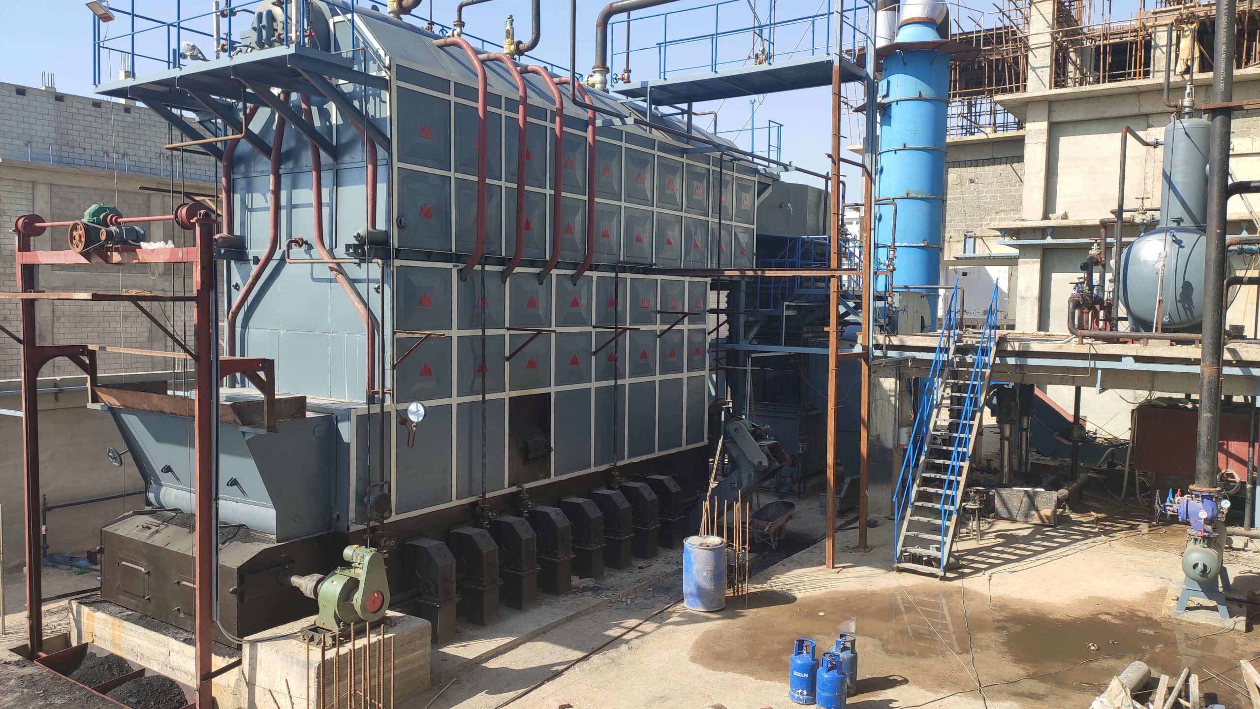
Wade Zhang

CEO of Taishan Group Taian Boao International Trade Co., Ltd. 30 years experience in Global industrial boiler market,  Over 300 boiler projects experience, including 21+ EPC projects. Projects span 30+ countries & regions, involving industries such as nuclear power, energy & electricity, municipal heating, mining, textiles, tires etc.

Key Factors Influencing Heat Transfer and Combustion Efficiency in Circulating Fluidized Bed Boilers Read More »

How to Measure the Thermal Efficiency of an Industrial Power Plant Boiler

How to Measure the Thermal Efficiency of an Industrial Power Plant Boiler

In industrial power generation, thermal efficiency is one of the most critical indicators of boiler performance. It reflects how effectively the boiler converts the chemical energy of fuel into usable steam energy for electricity production or industrial use. Failing to measure and monitor this metric can lead to fuel waste, reduced output, increased emissions, and even system degradation. Understanding how to accurately calculate thermal efficiency is key to optimizing energy usage and reducing operational costs.

The thermal efficiency of an industrial power plant boiler is measured by comparing the useful heat output (typically in the form of high-pressure steam) to the total energy input from the fuel source. This is typically done using either the Direct Method (input-output method) or the Indirect Method (heat loss method). Accurate thermal efficiency measurement requires data on steam production rate, fuel flow rate, flue gas temperature and composition, boiler pressure, and losses such as radiation and blowdown.

Let’s explore the standard methods and best practices used to calculate the real-world efficiency of power plant boilers.

What Is Thermal Efficiency and Why Is It Critical in Power Plant Boilers?

Power plants run on heat—whether it’s from burning coal, biomass, natural gas, or using nuclear reactions. But not all the heat produced ends up as useful electricity or process steam. A large portion of that energy is lost through exhaust gases, radiation, unburned fuel, or moisture evaporation. The ratio of useful heat extracted to total fuel energy input is what we call thermal efficiency. In power plant boilers, where massive volumes of fuel are consumed daily, even a few percentage points in thermal efficiency make the difference between profit and loss, compliance and violation, or sustainability and waste. It’s the single most important metric for evaluating a boiler’s energy performance.

Thermal efficiency in power plant boilers is the percentage of heat from fuel combustion that is successfully converted into useful steam energy. It measures how effectively the boiler transforms fuel input into thermal output and is critical because it directly affects fuel consumption, operating costs, CO₂ emissions, and overall power generation efficiency. Higher thermal efficiency means more energy is extracted from each unit of fuel, while lower efficiency indicates heat losses and operational inefficiencies. Optimizing thermal efficiency is essential for economic viability and environmental compliance.

In power generation, thermal efficiency defines how much energy your plant delivers—and how much it wastes.

Thermal efficiency is a key indicator of how effectively a boiler converts fuel into usable steam or energy.True

It directly impacts fuel costs, emissions output, and power plant performance.


🔍 Understanding Thermal Efficiency in Boiler Systems

TermDefinition
Thermal Efficiency (%)(Useful heat output / Fuel heat input) × 100
Useful Heat OutputEnergy transferred to generate steam
Fuel Heat InputTotal chemical energy in the fuel burned
InefficienciesHeat lost via flue gas, radiation, unburned carbon, blowdown

→ Power plant boilers typically have thermal efficiencies between 85–92%, depending on fuel type and system design.


📊 Example of Heat Balance in a Power Plant Boiler

Energy FlowApproximate Share (%)
Heat absorbed to generate steam85–90
Flue gas heat loss5–8
Radiation and convection losses1–2
Unburned fuel and blowdown losses0.5–1.5

→ The goal is to minimize every form of loss and drive output closer to 100% of input.


🛠 Why Thermal Efficiency Matters in Power Plant Boilers

FactorHow It Relates to Thermal Efficiency
Fuel CostsHigher efficiency = less fuel per unit of output
Emissions ComplianceLower fuel use = lower CO₂, NOx, SOx per MWh
Steam ProductionEfficient heat transfer = steady, reliable output
Heat Rate (kJ/kWh)Lower thermal efficiency = higher heat rate
Maintenance and Life CycleFouling and poor combustion reduce efficiency over time

→ A 1% efficiency improvement can yield hundreds of thousands in annual fuel savings in large power stations.


📈 Thermal Efficiency vs. Boiler Operating Parameters

Operating ParameterEfficiency Impact
Flue Gas TemperatureHigher temps = heat loss ↑, efficiency ↓
Oxygen (O₂) Level in Flue GasExcess air = efficiency ↓ if O₂ > 6%
Carbon Monoxide (CO)Indicates incomplete combustion = efficiency ↓
Steam Pressure/Temp ControlDeviations = lower energy conversion
Soot and Ash FoulingInsulates tubes = lowers heat transfer

→ Monitoring these metrics ensures efficiency stays at optimal levels.


🧪 Case Study – 150 MW Pulverized Coal Boiler Efficiency Optimization

  • Initial Condition:

    • Thermal efficiency: 84.2%

    • Flue gas temperature: 270°C

    • O₂ in stack: 6.5%

    • CO: 180 ppm

  • Actions Taken:

    • Burner realignment and excess air reduced

    • Added soot blower cycles

    • Installed O₂ trim system

  • Results:

    • Flue gas temp reduced to 195°C

    • CO < 70 ppm

    • Thermal efficiency improved to 89.1%

    • Annual coal savings: >12,000 tons


📏 Benchmark Thermal Efficiency Values

Boiler TypeTypical Efficiency (%)Remarks
Natural Gas Fired88–92Clean combustion, low ash
Coal Fired (PC/CFB)84–89Higher losses due to ash and air fans
Biomass Fired75–85Variable fuel, ash fouling risk
Combined Cycle HRSG90–94High efficiency due to gas turbine waste heat

→ Maintaining these levels requires ongoing performance tuning and maintenance.


🔧 How to Improve Thermal Efficiency

Improvement AreaAction
Air-Fuel Ratio ControlInstall O₂ trim systems, tune burners
Heat RecoveryUse economizer, air preheater, condensing economizer
Surface CleanlinessSchedule soot blowing, deslagging
Fuel Quality ManagementEnsure consistent calorific value and ash
Instrumentation and MonitoringLog flue gas temp, CO, O₂, efficiency trends

→ Efficiency isn’t a one-time achievement—it’s a continuous optimization process.


In conclusion, thermal efficiency is the most critical performance metric in power plant boilers, as it determines how effectively fuel energy is converted into usable steam and electricity. Poor efficiency translates directly into fuel waste, higher emissions, and operational cost overruns. By actively monitoring combustion quality, heat recovery, and system cleanliness, plant operators can sustain high efficiency and unlock long-term economic and environmental gains. In power generation, every percentage point in thermal efficiency is a percentage point of competitive advantage.

How Is the Direct Method Used to Measure Boiler Efficiency in Power Generation?

In large-scale power generation, knowing how effectively your boiler converts fuel into usable energy is essential for cost control and performance optimization. The Direct Method—also known as the input-output method—offers a simple and fast way to assess this efficiency. Unlike methods that require advanced gas analysis or detailed heat loss breakdowns, the Direct Method focuses on just two measurable values: the energy in the steam produced and the energy in the fuel consumed. This makes it a highly practical tool for operators to track boiler efficiency daily and identify changes in performance over time.

The Direct Method measures boiler efficiency by comparing the useful heat in the steam output with the total heat from the fuel burned. It involves calculating how much steam is generated per hour and determining how much fuel is used in that time. The heat energy in the steam is estimated using steam pressure and temperature, while the heat from the fuel is determined using the fuel’s calorific value. The ratio of these two values—useful output divided by fuel input—gives the boiler efficiency in percentage.

It’s a straightforward approach with high operational value—and no need for complex equations.

The Direct Method offers a fast and practical way to calculate boiler efficiency using only steam output and fuel input.True

It helps operators measure real-time performance without needing detailed combustion or flue gas data.


🔍 What Do You Need to Use the Direct Method?

Measurement RequiredDescription
Steam Flow Rate (kg/hr)How much steam the boiler produces
Steam Pressure & TemperatureUsed to estimate energy content of the steam
Feedwater TemperatureNeeded to calculate net heat added to water
Fuel Consumption (kg/hr or m³/hr)Total amount of fuel used during measurement period
Fuel Calorific Value (CV)Energy content per unit of fuel (from lab test or datasheet)

→ These are standard parameters already available in most power plant control rooms.


🛠 How the Direct Method Works (Without Complex Formulas)

  1. Measure the steam output:
    Use your steam flowmeter to find out how many kilograms of steam the boiler produces in one hour.

  2. Find the energy in that steam:
    Use steam tables to get the energy (in kcal or MJ) contained in the steam based on its pressure and temperature. Then subtract the energy already in the feedwater to get the actual energy gained.

  3. Measure the fuel used:
    Check how much fuel was consumed in that same hour—this could be coal in tons, gas in cubic meters, or biomass in kilograms.

  4. Know your fuel’s energy value:
    Use a lab report or fuel datasheet to find out the calorific value (how much energy one unit of that fuel provides).

  5. Compare output to input:
    Divide the energy delivered by the steam by the total energy supplied by the fuel. Multiply by 100 to get the efficiency percentage.

→ If your boiler generates more steam with less fuel, your efficiency is going up.


📊 Practical Example – Coal-Fired Power Boiler

ParameterValue
Steam Produced120,000 kg/hr
Steam Pressure / Temp65 bar / 480°C
Feedwater Temperature105°C
Fuel Used14,000 kg/hr (coal)
Calorific Value of Coal4,200 kcal/kg

Result:

  • Energy in steam is estimated based on steam conditions → let’s say ~66 kcal/kg of steam gained

  • Total steam energy = 120,000 × 66 = 7,920,000 kcal/hr

  • Energy from fuel = 14,000 × 4,200 = 58,800,000 kcal/hr

  • Efficiency = (7.92 ÷ 58.8) × 100 = ~86.5%

→ This means 86.5% of the fuel energy is being converted into useful steam.


📋 Benefits of Using the Direct Method

AdvantageWhy It Matters
Simple and fastNo need for flue gas analyzers or lab setups
Easy to automateCan be built into daily SCADA/PLC reports
Good for daily trackingIdentifies drops in performance immediately
Works with all fuelsWhether it’s coal, gas, biomass, or oil
Supports decision-makingHelps optimize burner settings and fuel strategies

→ Ideal for real-time operational feedback.


🧪 Case Study – Daily Monitoring in a Biomass Boiler

  • System: 10 TPH biomass-fired boiler

  • Issue: Gradual drop in steam output despite same fuel use

  • Method Used: Direct Method daily over two weeks

  • Findings:

    • Efficiency dropped from 83.1% to 76.4%

    • Investigation showed soot buildup in economizer

    • Cleaning restored flue gas temp from 240°C to 185°C

    • Efficiency returned to 84.2%

→ Regular Direct Method checks helped avoid unplanned shutdown and fuel waste.


🔧 Best Practices When Using the Direct Method

PracticePurpose
Use fresh fuel CV dataFuel quality changes; don’t rely on old numbers
Log steam and fuel hourlyHelps spot trends and anomalies
Check feedwater temp accuracyEssential for calculating true heat input
Verify steam meter calibrationIncorrect readings distort efficiency
Use during steady load conditionsAvoid measuring during load changes or trip events

→ Good data = trustworthy results.


In conclusion, the Direct Method is an operator-friendly, fast, and effective way to measure boiler efficiency in power generation environments. It focuses on what comes in (fuel) and what goes out (steam), using only standard plant data to deliver meaningful insights. When used consistently, it can help detect performance losses early, guide maintenance actions, and maximize fuel economy. In every power plant, knowing your efficiency in real-time is the first step to improving it.

What Is the Indirect Method and Which Heat Losses Does It Account For?

When precision and diagnostic detail are required in power plant boiler performance evaluation, engineers turn to the Indirect Method of boiler efficiency measurement. Unlike the Direct Method, which simply compares input and output, the Indirect Method dissects the boiler’s energy losses—identifying exactly where heat is wasted. By quantifying each form of thermal loss individually (such as flue gas loss, unburned carbon, radiation, and moisture evaporation), this approach allows for deeper insight into inefficiencies, making it a preferred tool for high-capacity, high-pressure boiler systems found in thermal power plants.

The Indirect Method measures boiler efficiency by subtracting the sum of all quantified heat losses from 100%. It identifies where and how heat is lost—including dry flue gas, moisture from fuel and air, unburned carbon, radiation, and combustion inefficiencies. This method provides detailed analysis for optimization by highlighting which loss contributes most to overall inefficiency, enabling corrective actions to improve thermal performance.

In short, the Indirect Method doesn’t just measure efficiency—it explains it.

The Indirect Method identifies individual heat losses to calculate boiler efficiency.True

By accounting for each type of thermal loss, it allows for detailed diagnostics and targeted performance improvements.


🔍 Overview of the Indirect Method

FeatureDescription
Efficiency FormulaEfficiency (%) = 100 – Σ (All Heat Losses %)
PurposePinpoint exact causes of efficiency loss
ApplicationsDiagnostic audits, tuning, long-term performance tracking
RequiresFlue gas composition, temperature, fuel analysis, ash content

→ The Indirect Method is data-intensive, but highly informative.


📏 Major Heat Losses Considered in the Indirect Method

Heat Loss TypeDescription
L1: Dry Flue Gas LossHeat carried away by hot combustion gases exiting the stack
L2: Evaporation of Water in FuelHeat used to evaporate moisture content in biomass/coal
L3: Loss due to H₂ in FuelHeat lost from evaporating water formed by burning hydrogen
L4: Unburned Carbon in Ash (UBC)Energy left in unburned fuel that is removed as bottom/fly ash
L5: Radiation and Convection LossesSurface heat loss from the boiler walls, ducts, and pipes
L6: Loss due to Incomplete Combustion (CO)Indicates poor combustion if high CO levels are detected
L7: Moisture in Combustion AirHeat used to vaporize humidity in air (minor in dry climates)

→ Each of these losses is expressed as a percentage of total fuel energy input.


📊 Example: Heat Loss Breakdown in a Coal-Fired Boiler (90 TPH)

Heat Loss ComponentValue (%)
L1: Dry Flue Gas Loss6.2
L2: Moisture in Fuel3.4
L3: Hydrogen in Fuel2.1
L4: UBC in Ash1.8
L5: Radiation/Convection1.5
L6: Incomplete Combustion (CO)0.6
L7: Moisture in Air0.3
Total Losses15.9%
Boiler Efficiency (Indirect)84.1%

→ This breakdown helps target which loss (e.g., dry flue gas or fuel moisture) to reduce first.


🛠 Data Required for the Indirect Method

Measurement/InputPurpose
Flue Gas Temperature (°C)Determines stack gas heat loss
Ambient Air Temperature (°C)Needed for radiation/convection calculations
O₂ or CO₂ in Flue Gas (%)Used to calculate excess air and flue gas volume
Fuel Analysis (proximate & ultimate)Moisture, hydrogen, ash, calorific value
Ash Content and UBC (%)For estimating unburned fuel loss
CO in Flue Gas (ppm)Identifies incomplete combustion

→ Accuracy of these inputs directly affects the reliability of the results.


🧪 Case Study – Biomass Boiler with 18% Moisture Fuel

  • Problem: High fuel consumption and ash carryover

  • Indirect Method Findings:

    • L1 (Dry Flue Gas) = 5.8%

    • L2 (Moisture in Fuel) = 6.7%

    • L4 (Unburned Carbon in Ash) = 2.2%

    • L5 (Radiation Loss) = 1.3%

  • Efficiency = 83.0%

  • Intervention:

    • Installed biomass dryer → reduced moisture to 10%

    • Improved grate air distribution for complete burn

  • Post-change Efficiency: 88.6%

→ Detailed loss analysis guided targeted investments with measurable gains.


📈 Comparison: Indirect vs. Direct Method

CriteriaDirect MethodIndirect Method
Data SimplicityHighModerate to complex
Time to CalculateFast (minutes)Slower (requires multiple inputs)
Identifies Loss SourcesNoYes
Preferred UseDaily monitoringAuditing, diagnostics
Accuracy with Varying FuelsLowerHigher

Use Direct Method for speed; Indirect for insight.


🔧 How to Use the Indirect Method Effectively

PracticePurpose
Regular Flue Gas TestingTracks CO, O₂, NOx, CO₂, temperature
Maintain Fuel Quality RecordsTracks changes in moisture, ash, calorific value
UBC Sampling of AshConfirms combustion efficiency
Calibrate Sensors and ProbesEnsures valid measurement inputs
Benchmark Monthly EfficiencyDetects degradation trends

→ A well-executed Indirect Method becomes a strategic performance tool.


In conclusion, the Indirect Method is a comprehensive approach to evaluating boiler efficiency by identifying and quantifying all significant heat losses. It empowers engineers and plant operators to pinpoint exactly where performance losses occur and take targeted corrective action—whether it’s reducing fuel moisture, optimizing air-fuel ratios, or improving combustion quality. In power plant operations, where margins are thin and fuel costs are high, the Indirect Method is not just a diagnostic tool—it’s an investment roadmap.

What Key Parameters and Instruments Are Needed for Accurate Measurements?

To evaluate boiler performance and combustion quality, operators and engineers rely on real-time and precise measurements of key process variables. Whether you’re calculating thermal efficiency, emissions compliance, or diagnosing heat losses, the accuracy of the results depends entirely on the quality of the data and instruments used. Poor sensor calibration, incomplete data, or wrong measurement locations can lead to significant errors in boiler diagnostics—leading to inefficient operation, excessive fuel consumption, or failure to meet regulatory limits. A well-instrumented boiler is the foundation of performance optimization.

Accurate measurements of boiler efficiency and combustion quality require key parameters such as fuel flow rate, steam output, flue gas composition (O₂, CO, CO₂), stack temperature, and feedwater enthalpy. These are obtained using precision instruments like steam flowmeters, calorimeters, gas analyzers, thermocouples, and pressure transmitters. Reliable and calibrated sensors, properly installed and monitored, are essential for calculating efficiency using both the Direct and Indirect Methods and for ensuring stable and safe boiler operation.

Good data enables good decisions. In boiler optimization, measurement is the master key.

Accurate boiler efficiency and performance measurements depend on high-quality instrumentation and critical parameter monitoring.True

Key variables like steam output, fuel input, flue gas composition, and temperatures must be measured precisely to enable valid performance assessment.


🔍 Key Parameters Required for Efficiency and Combustion Analysis

ParameterWhy It’s ImportantUse in Efficiency Method
Steam Flow Rate (kg/hr)Measures output energyDirect Method
Steam Pressure & TempUsed to determine steam enthalpyDirect Method
Feedwater TemperatureDetermines feedwater enthalpyDirect & Indirect Method
Fuel Consumption RateTracks input energy from solid, liquid, or gas fuelDirect Method
Fuel Calorific Value (GCV/NCV)Quantifies energy content of the fuelDirect & Indirect Method
Flue Gas TemperatureIndicates heat loss through exhaust gasesIndirect Method
O₂ in Flue Gas (%)Shows excess air and combustion completenessIndirect Method
CO/CO₂ in Flue GasIndicates incomplete combustionIndirect Method
Ash Content & UBC (%)Reveals combustion quality and unburned fuel lossesIndirect Method
Ambient Air Temp & HumidityUsed in accurate flue gas loss calculationIndirect Method

→ These parameters must be logged continuously or sampled frequently to ensure reliable boiler monitoring.


🛠 Essential Instruments for Accurate Measurement

Instrument / SensorFunctionInstallation Point
Steam Flowmeter (Turbine/DP/Ultrasonic)Measures steam output rateSteam header
Thermocouples / RTDsMeasure temperature of steam, flue gas, feedwaterSteam drum, stack, economizer
Pressure TransmittersFor steam pressure and feedwater inlet pressureSteam drum, feed lines
Fuel Flow MetersMeasures gas or oil input (mass or volume-based)Fuel supply lines
Coal/Biomass Belt WeighersMeasures solid fuel feed rateUnder feeders or conveyors
Gas Analyzers (O₂, CO, CO₂, NOx)Monitors flue gas compositionFlue gas duct (post-combustion)
Stack ThermometerMonitors exhaust gas temperatureChimney or outlet duct
Water Meters / Flow TransmittersMeasures make-up and blowdown water flowFeedwater and return lines
UBC Analyzer / Ash SamplerEstimates unburned carbon in fly ashAsh hopper or dust collector

→ Instrument calibration and proper maintenance are crucial for accuracy.


📊 Example: Instrument Configuration for a 50 TPH Biomass Boiler

ParameterValueMeasured By
Steam Flow Rate48,300 kg/hrUltrasonic Steam Flowmeter
Steam Pressure / Temp62 bar / 475°CPressure transmitter + RTD
Fuel Input (Wood Chips)6,200 kg/hrBelt Weigher
GCV of Fuel3,200 kcal/kgLab-tested proximate analysis
Flue Gas Temp (Stack)235°CThermocouple (K-Type)
O₂ in Flue Gas4.1%Zirconia Oxygen Analyzer
CO in Flue Gas95 ppmNDIR Gas Analyzer
Feedwater Temperature85°CRTD + SCADA logging

→ This setup supports both Direct and Indirect efficiency calculations.


🧪 Calibration and Accuracy Requirements

InstrumentRecommended Calibration FrequencyAccuracy Range Required
Steam FlowmetersEvery 6–12 months±1–2% of reading
O₂ and CO Gas AnalyzersMonthly calibration or auto-cal±0.5% O₂, ±5 ppm CO
Fuel Flow SensorsEvery 3–6 months±1% for gas, ±3% for solid
Temperature SensorsEvery 12 months±0.2–0.5°C
Pressure TransmittersEvery 12 months±0.25% FS

→ Inaccurate instruments lead to misleading efficiency results and incorrect decisions.


📈 Real-World Impact: Instrument Accuracy on Efficiency Calculation

ScenarioEfficiency ReportedTrue EfficiencyCause of Error
Steam meter over-reading 5%87.5%83.0%Calibration drift
Fuel GCV overestimated by 10%85.0%77.5%Old or unverified lab data
O₂ sensor reading stuck at 3.5%84.2%80.1%Failed flue gas sensor

→ Errors in a single instrument can distort system-wide performance metrics.


🔧 Best Practices for Measurement Accuracy

PracticeBenefit
Routine CalibrationMaintains data integrity
Instrument Redundancy (dual sensors)Avoids false readings from drift or failure
Automated SCADA/PLC Data LoggingEnables continuous trend analysis
Operator Training in Instrument UseEnsures proper use and interpretation
Cross-check with energy balancesValidates calculated vs. observed efficiency

→ Accuracy is not just hardware—it’s a system of procedures and people.


In conclusion, accurate boiler efficiency and combustion performance measurement relies on monitoring key parameters with high-precision instruments installed, calibrated, and managed correctly. From steam flow to flue gas composition, every data point contributes to an accurate picture of your boiler’s health and efficiency. With the right tools and discipline, plant teams can maximize output, minimize fuel costs, and maintain emissions compliance. In boiler operation, precision isn’t optional—it’s the difference between efficiency and excess.

How Do Fuel Type, Excess Air, and Flue Gas Temperatures Affect Efficiency Results?

Boiler efficiency is a dynamic metric—it doesn’t remain constant and is influenced by many operational parameters. Among these, fuel type, excess air level, and flue gas temperature are three of the most significant factors. Each directly impacts how completely combustion occurs, how well heat is transferred, and how much energy escapes through the stack. Incorrect combinations can lead to unburned fuel, excessive emissions, and wasted thermal energy, even if the boiler is mechanically sound. Understanding how these variables interact is essential for tuning your system toward maximum energy conversion and minimal losses.

Fuel type, excess air ratio, and flue gas temperature critically affect boiler efficiency. Fuels with high ash or moisture content reduce combustion quality and increase heat losses. Excess air improves combustion up to a point but too much dilutes flame temperature and increases stack losses. High flue gas temperature indicates poor heat recovery and fouling, lowering thermal efficiency. Efficient operation requires selecting the right fuel, optimizing air supply, and maintaining clean heat exchange surfaces to minimize energy losses and maximize fuel utilization.

Together, these factors determine whether your boiler performs at peak—or falls short.

Fuel type, excess air, and flue gas temperature significantly influence boiler efficiency.True

These parameters determine combustion quality and how much usable energy is retained or lost in the process.


🔍 1. Fuel Type and Its Impact on Efficiency

Fuel CharacteristicEfficiency Effect
Calorific Value (CV)Higher CV = more energy per kg of fuel
Moisture ContentHigher moisture absorbs combustion heat → efficiency ↓
Ash ContentHigh ash leads to fouling → reduces heat transfer
Volatile MatterAffects ignition, flame stability, and CO formation
Fuel TypeMoisture (%)Ash (%)CV (kcal/kg)Efficiency Range (%)
Natural Gas00~9,00088–92
Coal (Bituminous)8–1215–254,000–6,00084–89
Biomass (Wood)10–501–52,500–4,00070–85
RDF15–3015–203,000–4,00068–82

→ Lower moisture and ash fuels yield better combustion and higher efficiency.


🔍 2. Excess Air Ratio and Its Efficiency Tradeoff

Excess Air (%)O₂ (%) in Flue GasCombustion EffectEfficiency Effect
0–5<1.5%Risk of incomplete combustion (CO ↑)Efficiency ↓ (CO losses)
10–202.5–4.5%Ideal range for full combustion✅ Efficiency Optimized
25–30>5.5%Flame cooling, more flue gas volumeStack loss ↑ → Efficiency ↓
>35>7.5%Severe dilution of flame temperatureSignificant Efficiency ↓

→ Excess air must be balanced—not minimized—based on fuel reactivity.


🔍 3. Flue Gas Temperature and Heat Recovery

Flue Gas Temp (°C)System ConditionEfficiency Impact
160–190Clean heat surfaces, low excess air✅ Optimal heat recovery
200–230Moderate fouling or high excess airEfficiency ↓ 2–4%
240–270Poor heat transfer or over-firingEfficiency ↓ 5–8%
>280Severe fouling or tuning errorsEfficiency ↓ ≥10%

→ Flue gas temperature is a direct indicator of heat loss.


📊 Real-World Example – Effect of Fuel and Air on Efficiency

ConditionFlue Temp (°C)O₂ (%)CO (ppm)Efficiency (%)
Dry wood chips, tuned air1853.86085.6
Wet biomass, excess air 30%2506.514073.8
RDF, poor combustion air distribution2707.228068.5

→ Higher fuel quality + optimized air = 17% gain in efficiency over poor conditions.


🛠 Optimizing These Parameters Together

ParameterAction for High Efficiency
Fuel TypeUse dry, low-ash, high-CV fuel or pre-dry biomass
Excess AirTune O₂ to 3.0–4.5%, use O₂ trim systems
Flue Gas TempClean tubes, optimize heat recovery, reduce fouling

→ Combine control strategies for maximum synergistic benefit.


🧪 Case Study – Coal Boiler Retuned for Efficiency

  • Initial Issues:

    • Fuel: Bituminous coal (22% ash, CV 4,200 kcal/kg)

    • O₂ = 6.8%, CO = 220 ppm

    • Flue gas temp = 265°C

    • Efficiency = 76.3%

  • Actions Taken:

    • Adjusted excess air to target O₂ of 4.0%

    • Cleaned superheater and economizer

    • Installed automatic O₂/CO monitoring

  • Results:

    • CO = 80 ppm

    • Flue temp = 190°C

    • Efficiency = 86.1% (+9.8%)


📈 Efficiency Loss per 10°C Increase in Flue Gas Temp

Fuel TypeApprox. Efficiency Drop (%)
Natural Gas0.5–0.7%
Coal0.8–1.0%
Biomass0.9–1.2%

→ Fouling that adds 50°C = 5–6% loss in many boilers.


In conclusion, boiler efficiency is deeply influenced by the combination of fuel type, excess air ratio, and flue gas temperature. Each factor individually affects combustion quality and heat loss, but together they define the system’s energy performance. For the highest efficiency, operators must ensure consistent, dry fuel, use precise air control, and keep heat transfer surfaces clean and optimized. In energy systems, efficiency isn’t just about technology—it’s about mastering the variables that drive it.

How Can Thermal Efficiency Data Help Improve Power Plant Output and Fuel Economy?

Power plants operate on narrow economic margins where even a 1–2% shift in performance can mean millions in cost or revenue differences over time. In this high-stakes environment, thermal efficiency data serves as both a diagnostic tool and a strategic compass. When accurately tracked and analyzed, this data reveals inefficiencies, predicts maintenance needs, and supports decisions that increase power output per unit of fuel. Without it, operators are flying blind—burning more fuel than necessary, reducing equipment life, and emitting more pollutants. With it, they gain a quantifiable path to optimization, fuel savings, and sustained profitability.

Thermal efficiency data helps improve power plant output and fuel economy by providing real-time insights into how effectively fuel energy is converted into steam or electricity. Monitoring this data enables operators to detect losses, optimize combustion, adjust air-fuel ratios, schedule predictive maintenance, and benchmark performance. Over time, this leads to improved steam generation, reduced fuel consumption, and lower operating costs. Thermal efficiency tracking transforms raw operational data into actionable strategies for continuous improvement.

Your efficiency data isn’t just a number—it’s the roadmap to operational excellence.

Thermal efficiency data is essential for optimizing power plant output and reducing fuel consumption.True

By identifying performance trends and loss sources, it allows targeted actions that improve energy conversion and reduce waste.


🔍 What Is Thermal Efficiency Data in Power Plants?

MetricDescription
Thermal Efficiency (%)Measures ratio of energy output to energy input (fuel)
Steam-to-Fuel RatioKg steam produced per kg of fuel burned
Heat Rate (kJ/kWh)Inverse of efficiency; shows energy input per electricity unit
Boiler Efficiency LogsDaily/real-time records showing combustion and heat transfer performance

→ These metrics form the core indicators of boiler and turbine effectiveness.


📏 How Efficiency Data Links to Output and Fuel Economy

Efficiency MetricOperational Impact
Higher Thermal EfficiencyMore steam or electricity from same fuel quantity
Improved Heat RateLower energy cost per MWh
Consistent EfficiencyStable generation and reduced maintenance cost
Decreasing EfficiencyEarly warning of fouling, combustion issues, or leaks

→ Tracking trends in efficiency helps predict problems before they cost money.


📊 Example – Efficiency Improvement Impact on Fuel and Output

ParameterBefore OptimizationAfter Optimization
Fuel Consumption (TPD)600540
Steam Output (TPH)280290
Thermal Efficiency (%)76.584.7
Heat Rate (kJ/kWh)11,80010,400
Annual Fuel Savings~22,000 tons/year

→ A modest 8.2% increase in efficiency generated millions in fuel savings.


🧪 Case Study – Real-Time Efficiency Dashboard Integration

  • Plant: 300 MW Coal-Fired Power Station

  • Problem: Variable generation output, high fuel cost

  • Intervention:

    • Installed real-time boiler efficiency dashboard (Direct + Indirect method)

    • Integrated steam, fuel, flue gas, and O₂ readings

    • Used heat rate data to trigger soot blower, O₂ trim, and burner adjustments

  • Result:

    • Efficiency rose from 82.6% to 89.1%

    • Fuel usage per MWh dropped by 8.5%

    • Improved generation availability by 4.3%

→ Efficiency visibility led to actionable changes across O&M departments.


📈 Operational Actions Triggered by Thermal Efficiency Data

Efficiency IndicatorCorrective Action
Flue Gas Temp ↑Soot blowing, inspect fouling in economizer
O₂ > 6%Adjust excess air and burner dampers
CO ↑ / Steam ↓Tune combustion or check flame alignment
Steam-to-Fuel Ratio ↓Investigate feedwater, check for leaks or scale
Ash Content ↑Modify grate speed, clean slagging zones

→ Data makes decisions evidence-based, not guess-based.


🛠 Efficiency Monitoring Tools and Systems

Tool/SystemRole in Fuel Economy & Output Optimization
SCADA/PLC-Based MonitoringReal-time tracking of efficiency variables
Energy Management Systems (EMS)Analyze trends, suggest optimizations
O₂ Trim ControlAutomated excess air tuning
Flue Gas AnalyzersCO, CO₂, O₂ → combustion diagnostics
Digital Twin ModelsSimulate performance based on real input data

→ These tools convert raw data into strategic decisions.


📋 Efficiency Improvement Strategies Informed by Data

StrategyEfficiency Data Input UsedBenefit
Combustion OptimizationO₂, CO, fuel ratio, steam outputLower fuel per ton steam
Maintenance SchedulingFlue temp, ΔP, steam/fuel ratio trendsFewer outages, optimized timing
Heat Recovery EnhancementsFlue gas lossesHigher energy recovery
Fuel Switching DecisionsCV vs. efficiency outcomeHigher output per fuel unit
Operator TrainingPerformance deviation from normConsistent efficiency behaviors

→ Efficiency data is the source code for every power plant improvement.


🔧 Best Practices for Using Thermal Efficiency Data

PracticePurpose
Daily Efficiency Log ReviewsSpot declining trends early
Baseline BenchmarkingSet targets based on design vs. actual
Variance AnalysisCompare shifts in output, fuel, or flue gases
Real-Time Alarms for Efficiency LossesImmediate operator response
Efficiency KPI IntegrationTie staff KPIs to boiler performance

→ Turn data into accountability and results.


In conclusion, thermal efficiency data empowers power plants to operate smarter, cleaner, and more cost-effectively. By identifying performance issues and opportunities, it enables better decisions on fuel management, output optimization, and maintenance planning. With accurate efficiency monitoring, plants can boost generation without burning more fuel—and that’s the hallmark of a high-performance energy operation. In power generation, what gets measured gets improved—and what gets improved gets profitable.

🔍 Conclusion

Measuring the thermal efficiency of an industrial power plant boiler is essential for achieving peak performance, minimizing fuel consumption, and reducing carbon emissions. Whether using the Direct or Indirect Method, accurate monitoring of heat input and output helps identify system inefficiencies and opportunities for improvement. With consistent measurement and analysis, power plant operators can ensure that their boiler systems deliver maximum energy yield and long-term reliability.


📞 Contact Us

💡 Need support measuring or optimizing your power boiler’s efficiency? Our engineering team provides in-depth performance audits, combustion tuning, and energy optimization solutions for power plant boilers of all sizes.

🔹 Contact us today and start maximizing the energy efficiency of your power plant boiler! ⚡🔥📊

FAQ

What is thermal efficiency in an industrial power plant boiler?

Thermal efficiency is the ratio of the boiler’s useful heat output (typically steam for electricity generation) to the total energy input from fuel combustion. It reflects how effectively the boiler converts fuel energy into usable steam or power.

What methods are used to measure boiler thermal efficiency?

There are two widely accepted methods:

  1. Direct Method – Based on output vs. input energy.

  2. Indirect Method – Based on measuring and subtracting various heat losses from 100%.
    These methods are compliant with standards like ASME PTC 4 and ISO 16528.

How does the Direct Method work for power plant boilers?

The Direct Method calculates efficiency using:

Efficiency (%) = (Steam Output × Enthalpy Gain) / (Fuel Input × Calorific Value) × 100
It’s fast and straightforward but doesn’t identify the specific areas of loss.

What is the Indirect Method and why is it more diagnostic?

The Indirect Method calculates efficiency by summing all measurable heat losses—such as flue gas loss, radiation loss, blowdown, moisture in fuel, and unburnt fuel—and subtracting them from 100%.

Efficiency (%) = 100 – (Total Heat Losses)
This approach helps pinpoint inefficiencies in combustion, insulation, and fuel quality.

Why is thermal efficiency monitoring essential in power plant boilers?

Monitoring efficiency improves fuel utilization, lowers CO₂ emissions, reduces operating costs, and enhances plant reliability. It’s also a key metric in energy audits and compliance with environmental regulations and carbon reduction goals.

References

  1. Boiler Efficiency Measurement Techniqueshttps://www.energy.gov

  2. ASME PTC 4: Fired Steam Generatorshttps://www.asme.org
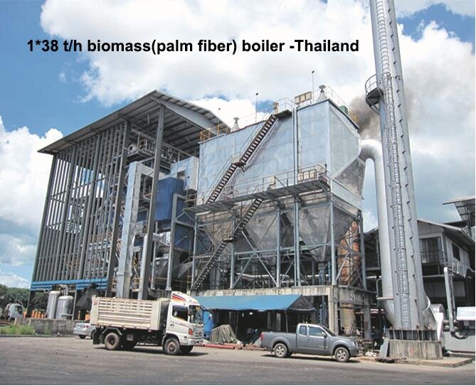
  3. Heat Loss Analysis in Power Boilershttps://www.sciencedirect.com

  4. Energy Efficiency in Industrial Boilershttps://www.researchgate.net

  5. Thermal Performance and Auditing Guidelineshttps://www.epa.gov

  6. Boiler Optimization in Power Plantshttps://www.bioenergyconsult.com

  7. Indirect Method for Large Combustion Systemshttps://www.mdpi.com

  8. Real-Time Monitoring of Boiler Efficiencyhttps://www.automation.com

  9. IEA Boiler Energy Efficiency Recommendationshttps://www.iea.org

  10. Fuel Quality and Efficiency in Power Boilershttps://www.energysavingtrust.org.uk

Wade Zhang

CEO of Taishan Group Taian Boao International Trade Co., Ltd. 30 years experience in Global industrial boiler market,  Over 300 boiler projects experience, including 21+ EPC projects. Projects span 30+ countries & regions, involving industries such as nuclear power, energy & electricity, municipal heating, mining, textiles, tires etc.

How to Measure the Thermal Efficiency of an Industrial Power Plant Boiler Read More »

Key Factors Influencing Heat Transfer and Combustion Efficiency in Industrial Biomass Boilers

Key Factors Influencing Heat Transfer and Combustion Efficiency in Industrial Biomass Boilers

Industrial biomass boilers are gaining popularity for their sustainability, fuel flexibility, and carbon-neutral benefits. However, achieving high heat transfer and combustion efficiency is not automatic. Biomass fuels vary widely in composition and behavior, and if combustion and heat exchange processes are not optimized, it can result in incomplete fuel burn, low thermal output, fouling, and high emissions. Understanding the variables that affect efficiency is essential for operators aiming to reduce fuel consumption, maintenance costs, and environmental impact.

The heat transfer and combustion efficiency in industrial biomass boilers are influenced by factors such as fuel type and moisture content, particle size, combustion air distribution, boiler design, furnace temperature, flue gas velocity, and the condition of heat exchanger surfaces. Inconsistent fuel properties and poor combustion control can reduce flame temperature, increase unburned carbon, and lead to ash fouling on heat transfer surfaces. Proper fuel preparation, combustion tuning, and maintenance are critical to sustain long-term efficiency.

Let’s examine the key performance variables that determine how efficiently your biomass boiler converts fuel energy into usable heat.

SZL small(10)(1)

How Does Biomass Fuel Type and Moisture Content Impact Combustion Efficiency?

Biomass is widely promoted as a renewable alternative to fossil fuels in industrial boiler systems, but its combustion performance varies greatly depending on fuel type and moisture content. Unlike standardized fuels like natural gas or oil, biomass feedstocks such as wood chips, pellets, agri-residues, and RDF can differ significantly in energy content, ash behavior, and moisture levels. These variations directly affect combustion stability, flame temperature, and thermal efficiency. High-moisture or low-calorific fuels absorb combustion heat to evaporate water, leading to reduced steam output, increased flue gas temperature, and incomplete burning. Poor fuel selection or unaddressed moisture levels can undermine both performance and emissions compliance.

Biomass fuel type and moisture content impact combustion efficiency by determining the energy density and the amount of heat lost to water evaporation. High-moisture fuels absorb combustion heat to evaporate water, reducing flame temperature and steam generation. Low-quality fuels with high ash or volatile matter may lead to slagging or incomplete combustion. Fuel types like wood pellets offer higher and more stable efficiency due to low moisture and uniform properties, whereas raw agri-residues or wet chips require drying, optimized combustion air, and ash management. Selecting the right fuel and controlling moisture is critical for maintaining high efficiency in biomass boilers.

Fuel quality is not optional—it’s the foundation of combustion performance.

Biomass fuel type and moisture content significantly affect boiler combustion efficiency.True

Moisture reduces effective energy output and low-grade biomass can cause slagging, fouling, and unstable combustion.


🔍 Key Biomass Fuel Characteristics Affecting Efficiency

ParameterEffect on Combustion Performance
Moisture Content (%)High moisture absorbs heat, cools flame, lowers efficiency
Calorific Value (kcal/kg)Directly affects steam output per kg fuel
Ash Content (%)Impacts fouling, slagging, particulate emissions
Volatile Matter (%)Influences ignition and flame stability
Bulk Density (kg/m³)Affects fuel feeding and storage logistics

→ Moisture and calorific value are most critical for efficiency.


📏 Comparison of Biomass Fuels by Moisture and Efficiency Potential

Biomass TypeMoisture (%)CV (kcal/kg)Ash (%)Typical Efficiency (%)
Wood Pellets6–104200–46000.5–1.085–88
Wood Chips (dry)15–253200–38001–278–84
Rice Husk8–122900–320015–2070–75
Straw Bales12–182800–32006–1068–74
Wet Sawdust35–552000–25001–260–68 (if undried)

→ Dry, low-ash fuels = better efficiency and cleaner combustion.


🛠 Moisture Content and Energy Loss Explained

Moisture Level (%)Energy Lost to Evaporation (%)Combustion Effect
<10%Minimal (<5%)High flame temp, fast ignition
15–20%Moderate (5–10%)Some cooling, manageable loss
25–35%High (10–20%)Slower combustion, lower efficiency
>40%Very high (>25%)Incomplete burn, high flue temp, CO↑

→ Each 10% increase in moisture may reduce boiler efficiency by 2–5%.


📊 Performance Impact of Moisture in Wood Chips (Real Data)

Moisture (%)Flue Gas Temp (°C)CO (ppm)Steam Output (TPH)Efficiency (%)
15%1856510.285.6
25%210959.179.2
35%2451808.272.4

→ Proper fuel drying or selection leads to dramatic performance improvement.


🧪 Case Study – Rice Husk vs. Wood Pellet Boiler

  • System: 12 TPH biomass-fired FBC boiler

  • Fuel A: Rice husk (12% moisture, 16% ash)

  • Fuel B: Wood pellets (8% moisture, 0.8% ash)

Performance MetricRice HuskWood Pellets
Steam Output (TPH)11.412.0
Flue Gas Temp (°C)232188
CO Emissions (ppm)18045
Thermal Efficiency (%)74.886.7

→ Switching fuel improved efficiency by ~12% and reduced CO by ~75%.


🔧 Operational Adjustments for High-Moisture Biomass

Adjustment TypeAction
Combustion AirIncrease primary air for drying zone
Grate SpeedSlow down to allow moisture evaporation
Fuel Feed RateReduce to maintain combustion temp
Secondary Air TuningPromote burnout, reduce CO
Flue Gas Recirculation (FGR)Stabilizes temp, lowers excess air

→ Control strategies must adapt to fuel variability.


📈 Best Practices to Improve Biomass Combustion Efficiency

PracticeBenefit
Pre-drying fuelsReduces energy loss, improves burn
Fuel Quality Testing (moisture, CV)Allows proper boiler tuning
Feedstock homogenizationPrevents load swings, stabilizes flame
Soot blowing and ash managementMaintains clean heat transfer surfaces
Ash fusion temperature monitoringPrevents slagging and fouling

→ Combining fuel control with automated combustion tuning yields the best outcomes.


In conclusion, biomass fuel type and moisture content are two of the most critical factors influencing combustion efficiency in biomass-fired boilers. High-moisture or high-ash fuels reduce flame temperature, increase flue gas loss, and impair complete combustion. To maintain high efficiency, it is essential to select low-moisture, energy-dense fuels (like wood pellets) or implement drying and control systems for variable-quality inputs. In biomass combustion, the fuel is not just fuel—it is a process variable that defines your energy performance.

Why Is Fuel Particle Size and Uniformity Important for Stable Combustion?

Stable and efficient combustion in a biomass or coal-fired boiler depends on a wide range of variables—but fuel particle size and consistency are among the most influential. Whether you’re using wood chips, pellets, rice husk, or pulverized coal, inconsistent particle size can cause serious combustion issues. Fine particles ignite too quickly, generating flashback or smoke, while oversized chunks burn slowly or incompletely, creating cold spots, carbon monoxide (CO), and unburned carbon losses. Non-uniform fuel feed also results in flame instability, pressure fluctuations, fouling, and poor heat transfer. Uniformity ensures consistent burning rates, even air-fuel mixing, and balanced heat generation—cornerstones of boiler efficiency and emissions control.

Fuel particle size and uniformity are critical for stable combustion because they directly affect how consistently and completely the fuel burns. Uniform particle size allows for even distribution on the grate or in the combustion chamber, resulting in consistent flame shape, heat release, and air-fuel mixing. Irregular or oversized particles cause incomplete combustion, higher CO emissions, ash carryover, and flame instability. Consistent size also ensures smooth fuel feeding, reduces clinkering, and improves overall thermal efficiency.

Fuel that flows, ignites, and burns uniformly ensures that your boiler operates smoothly and cleanly.

Fuel particle size and uniformity play a vital role in maintaining stable combustion.True

Consistent particle size allows for uniform ignition, steady flame behavior, and complete combustion, reducing emissions and energy losses.


🔍 The Science Behind Particle Size and Combustion Behavior

Particle Size (mm)Combustion CharacteristicEffect on Performance
<3 mm (fine dust)Fast ignition, flashback riskHigh CO, smoke, inconsistent heat
3–15 mm (ideal)Steady ignition and complete burnStable flame, high efficiency
>20 mm (chunks)Slow ignition, incomplete combustionHigh unburned carbon, fouling, CO ↑

→ Fuels should be pre-processed to the optimal size range for the specific combustion system.


📏 Typical Fuel Size Requirements by System Type

Boiler TypeIdeal Fuel Size RangeReason
Grate-fired biomass5–50 mmGood distribution and burnout on grates
Fluidized bed (FBC)1–6 mmPrevents bed agglomeration, even mixing
Pulverized coal system<0.3 mm (300 microns)Rapid ignition and high surface area
Stoker-fired boiler10–25 mmConsistent burn on slow-moving grate

→ Deviations from these ranges lead to instability, incomplete combustion, or mechanical jamming.


🛠 How Size and Uniformity Affect Key Combustion Parameters

Combustion FactorEffect of Inconsistent Fuel Size
Ignition DelayUneven timing = hot/cold zones, CO spikes
Flame ShapeNon-uniform = pulsating, off-centered flame
Air-Fuel RatioUneven fuel = localized excess or deficiency
Heat ReleaseVariable = steam pressure swings
Ash ResidueHigher = fouling, slagging, unburned carbon

→ These instabilities reduce both efficiency and reliability.


📊 Case Study – Wood Chip vs. Screened Pellet Performance

Fuel TypeParticle Size UniformityFlame StabilityCO (ppm)Thermal Efficiency (%)
Raw wood chipsPoor (5–80 mm)Unstable24074.2
Screened pelletsHigh (6–8 mm)Stable5587.1

→ Uniform pellet size produced 40% lower CO and ~13% higher efficiency.


🔧 Operational Challenges with Irregular Fuel Size

ProblemRoot CauseImpact
Fuel feeder jammingLarge or sticky particlesDowntime and uneven load
Grate overloading or clinkeringLarge chunks or high finesLocal overheating, slagging
CO or flame-out alarmsRapid burn of fines or cold fuel zonesTripped systems, unsafe operation
Ash carryoverIncomplete burn of large particlesMore PM, strain on baghouse/ESP

→ Mechanical and combustion issues increase maintenance and emissions risk.


🧪 Solutions for Fuel Size Optimization

SolutionImplementation Detail
Shredding/ChippingUse biomass chipper to produce 20–50 mm chips
PelletizingConverts fines and dust into uniform pellets
Screening SystemsRemove oversize and fines before feeding
Fuel Bunker AgitatorsPrevent bridging and flow interruptions
In-Line CrushersPulverize coal or biomass prior to combustion

→ Equipment must be tailored to both fuel and boiler type.


📈 Efficiency Gains from Uniform Fuel Handling

Before OptimizationAfter Fuel Size Control
Steam Output = 9.2 TPHSteam Output = 10.3 TPH
CO = 210 ppmCO = 70 ppm
O₂ = 7.5% (excess)O₂ = 4.0%
Efficiency = 76.5%Efficiency = 86.4%

Uniform fuel = higher output, cleaner burn, and reduced fan/pollution control effort.


In conclusion, fuel particle size and uniformity are critical to achieving stable, complete, and efficient combustion in industrial boilers. Inconsistent fuel causes ignition issues, combustion instability, increased emissions, and equipment failures. Whether burning coal or biomass, selecting the right particle size and ensuring uniform feed gives you control over your flame—and your bottom line. In solid fuel combustion, consistency is not just quality—it’s performance.

Biomass boilers (9)

How Does Air Distribution and Excess Air Ratio Affect Combustion Quality?

Efficient and clean combustion doesn’t happen by chance—it depends on precisely how air is introduced and mixed with fuel. In solid, liquid, or gas-fired boilers, both the distribution of combustion air (primary, secondary, and tertiary) and the excess air ratio (air beyond theoretical requirements) determine how completely fuel is burned. Poor air distribution leads to local rich or lean zones, incomplete combustion, high CO, soot, and even flame instability. Too much excess air dilutes flame temperature and wastes energy in the flue gas. Too little, and you get smoke, CO, and unburned fuel. Getting this balance right is essential for stable combustion, low emissions, and high thermal efficiency.

Air distribution and excess air ratio affect combustion quality by controlling the oxygen availability and mixing within the furnace. Proper air distribution ensures that oxygen reaches all fuel particles at the right time and location for complete combustion, while the correct excess air ratio ensures a balance between minimizing CO and NOx emissions and maximizing efficiency. Insufficient air causes incomplete combustion and high CO; too much air lowers flame temperature and increases stack losses. Uniform and staged air introduction helps achieve stable flame, full burnout, and regulatory compliance.

In combustion control, how air enters matters just as much as how much enters.

Air distribution and excess air ratio are key factors in determining combustion quality and efficiency.True

Proper air mixing ensures full combustion while avoiding energy losses and emissions linked to too little or too much air.


🔍 Understanding Air Distribution in Combustion

Air TypeFunctionTypical Introduction Location
Primary AirDelivers air for initial ignition and dryingBelow the fuel bed or burner
Secondary AirAids in flame shaping and volatile burnoutMid-furnace or above the bed
Tertiary AirFinal burnout of CO and hydrocarbonsNear furnace exit or overfire
Overfire Air (OFA)Lowers NOx by staging combustionAbove flame zone

→ Staged and well-distributed air flow supports complete combustion and emission control.


📏 Impact of Excess Air Ratio on Combustion Performance

Excess Air (%)O₂ (%)CO (ppm)NOx (mg/Nm³)Efficiency Impact
0–5%<1%>500LowIncomplete combustion (CO↑)
10–20%2.5–4.5%<100Optimal✅ High efficiency zone
>25%>5.5%<50High (thermal NOx↑)Heat loss ↑, NOx↑
>40%>7.5%<20ModerateVery inefficient

→ A target excess air range of 10–20% is ideal for most boilers.


🔧 Combustion Quality Indicators Affected by Air Control

IndicatorWhat Poor Air Distribution Causes
CO LevelsIncomplete combustion in rich zones
Flame ShapeOff-centered or unstable flame
Unburned Carbon (UBC)Residual fuel in ash or emissions
Flue Gas O₂Too low = CO↑, too high = efficiency↓
NOx FormationHigh flame temp from excess air → NOx↑

→ The best combustion occurs when air and fuel are uniformly and proportionally mixed.


📊 Example: Air Distribution Optimization in a Biomass Boiler

ConditionCO (ppm)O₂ (%)Stack Temp (°C)Efficiency (%)
Poor air distribution (manual)2806.824574.2
Optimized primary/secondary air803.919086.3

→ Better air distribution cut CO by 70% and improved efficiency by over 12%.


🧪 Case Study – Coal-Fired 30 TPH Boiler with OFA Retrofit

  • Initial Issue: High NOx (480 mg/Nm³), CO spikes, poor flame control

  • Diagnostics: Excess air at 25–30%, poor volatile burnout

  • Actions:

    • Installed overfire air ports

    • Staged secondary air and tuned primary airflow

    • Added real-time O₂/CO monitoring

  • Results:

    • NOx reduced to 240 mg/Nm³

    • CO < 60 ppm

    • Efficiency rose from 78.4% to 84.7%


🛠 Best Practices for Air Distribution and Excess Air Control

PracticeBenefit
Burner Air Register AdjustmentOptimizes swirl, flame shape
Air Duct BalancingEnsures uniform flow to multiple ports
Use of Flow Nozzles or DampersFine-tunes air per zone
O₂ Trim Control SystemMaintains optimal excess air dynamically
Periodic Flame Imaging or IRIdentifies air starvation or oversupply

→ Intelligent controls + proper ducting = clean, consistent combustion.


📈 Air Control Optimization and Performance Gains

Before OptimizationAfter Tuning Air Distribution
O₂ = 7.2%O₂ = 3.8%
CO = 220 ppmCO = 55 ppm
Unburned Carbon in Ash = 8%1.8%
Boiler Efficiency = 75.2%85.5%

→ Correct air distribution = better burnout, fewer emissions, and lower costs.


In conclusion, air distribution and excess air ratio are central to achieving high combustion quality, efficiency, and emissions compliance. Poor air control leads to energy waste, unburned fuel, high CO, and unstable operation. By distributing air in stages, tuning for the right excess, and monitoring flue gas in real-time, boilers can achieve a balanced flame, complete combustion, and optimal fuel use. In boiler operation, controlling how air flows is the key to making fuel burn its best.

What Role Do Ash Content and Fouling Play in Reducing Heat Transfer Efficiency?

In biomass and coal-fired boiler systems, ash content and fouling are two major performance killers. When fuels contain high levels of mineral residue (ash), these non-combustible particles get carried by flue gases and deposit on internal heat exchange surfaces. Over time, these deposits form insulating layers—called fouling—on water walls, superheaters, economizers, and air preheaters. The result is reduced heat transfer from hot gases to steam or water, increasing flue gas temperatures, reducing steam output, and driving up fuel consumption. Additionally, excessive fouling can lead to corrosion, tube failure, and unplanned downtime. Effective fuel management and cleaning are essential to minimize these losses.

Ash content and fouling reduce heat transfer efficiency by forming insulating deposits on heat exchanger surfaces inside the boiler, which block the flow of thermal energy from the combustion gases to the steam or water. High-ash fuels produce more particulate matter that adheres to tubes, especially at high temperatures. These deposits increase the thermal resistance of heat transfer surfaces, raising flue gas temperatures and requiring more fuel to maintain output. If not cleaned regularly, fouling also leads to metal overheating, slagging, and mechanical failure.

Clean tubes mean better heat absorption—and lower fuel bills.

High ash content and fouling significantly reduce the thermal efficiency of steam boilers.True

Ash deposits act as an insulator, hindering heat transfer and forcing the system to consume more fuel to maintain steam output.


🔍 What Is Ash and How Does It Cause Fouling?

ParameterDescription
Ash Content (%)Non-combustible mineral residue in fuel
FoulingAccumulation of ash/slag on heat exchanger surfaces
SlaggingMolten ash forming crusts on furnace walls
SootingCarbon-rich fouling from incomplete combustion

→ Fouling acts like a thermal blanket on boiler surfaces—blocking heat transfer.


📏 Ash Content of Common Fuels

Fuel TypeTypical Ash (%)Fouling RiskComments
Wood Pellets0.5–1.5LowClean combustion, minimal fouling
Wood Chips1–3Low–ModerateDepends on bark and moisture content
Rice Husk15–20HighVery fine ash, silica-related fouling
Coal (Bituminous)10–25HighHeavy ash loading and fouling
Straw and RDF8–15Moderate–HighVariable ash behavior

→ High-ash fuels require more cleaning, stronger fans, and durable surfaces.


📊 Impact of Fouling on Heat Transfer Efficiency

Ash Layer ThicknessEffect on Heat Transfer (%)Fuel Use Increase (%)
0.1 mm↓ 5–8%↑ 2–3%
0.5 mm↓ 15–20%↑ 5–7%
1.0 mm↓ >30%↑ 10–15%

→ Even thin ash layers can cost thousands in wasted fuel annually.


🧪 Case Study – Rice Husk Boiler Fouling Impact

  • Fuel: Rice husk (17% ash), 10 TPH fluidized bed boiler

  • Symptoms:

    • Flue gas temperature rose from 195°C to 255°C

    • CO emissions increased

    • Steam output dropped by 12%

  • Findings:

    • Economizer and superheater coated with 1.2 mm of ash

    • UBC (unburned carbon) in ash = 7.5%

  • Action:

    • Manual offline cleaning

    • Upgraded soot blowers to high-pressure air

    • Added ash softening additive (kaolin)

  • Result:

    • Flue gas temp dropped to 200°C

    • Steam output restored to 10.2 TPH

    • Efficiency rose from 74.2% to 83.8%


🛠 Fouling-Prone Areas in Industrial Boilers

ComponentFouling TypeCleaning Required
Furnace WallsSlagging, sootMechanical scraping, air jets
Superheater TubesSilica, alkali ashSoot blowers, thermal cleaning
EconomizerDense ash, fly ashHydroblasting, manual brushing
Air PreheaterTar and sticky ashOffline steam or air cleaning
Water-side (scale)Calcium/Mg foulingChemical descaling

→ These areas must be monitored via ΔP, stack temp, and visual inspection.


📈 Flue Gas Temperature vs. Fouling Severity

Flue Gas Temp (°C)Indicated ConditionEfficiency Impact
180–200Clean heat transfer✅ Optimal zone
220–240Moderate fouling present↓ Efficiency 3–7%
>260Severe fouling/blockage↓ Efficiency ≥10%

→ Rising stack temps = thermal red flag.


🔧 Maintenance Best Practices to Combat Fouling

Maintenance TaskFrequencyPurpose
Online Soot BlowingDaily/automaticKeeps tubes clear of dry ash
Offline Tube CleaningMonthly/quarterlyRemoves hardened deposits
Ash Monitoring (UBC, texture)WeeklyIndicates combustion/fouling issues
Flue Gas Analysis (O₂, CO)ContinuousDetects combustion imbalance
Stack Temperature LoggingDailyTracks fouling and thermal trends

→ Combining monitoring + cleaning maintains long-term efficiency.


📋 Fouling Prevention Techniques

StrategyEfficiency Benefit
Fuel Selection (low ash)Reduces deposit volume
Additives (kaolin, dolomite)Raise ash fusion point → fewer clinkers
Air-Fuel OptimizationComplete burn reduces soot and CO
Grate/Furnace DesignImproves ash discharge, prevents bridging
Automated Cleaning SystemsSustains performance with minimal downtime

→ Prevention is cheaper than fuel loss or unplanned shutdowns.


In conclusion, ash content and fouling are leading causes of heat transfer loss in solid fuel-fired boiler systems. High-ash fuels generate heavy deposits that insulate heat exchanger surfaces, forcing boilers to consume more fuel to meet demand. Left unchecked, this leads to skyrocketing flue temperatures, falling efficiency, and mechanical degradation. To combat this, fuel selection, regular cleaning, and real-time performance monitoring must be built into the operation strategy. In high-efficiency combustion, clean surfaces mean clean performance.

How Do Combustion Temperature and Flue Gas Characteristics Influence Thermal Performance?

In any steam boiler system, combustion transforms fuel into thermal energy. But how efficiently that transformation occurs depends heavily on combustion temperature and flue gas characteristics. The higher and more stable the flame temperature, the more heat is transferred into the working fluid—provided that the boiler is designed to capture it. On the other hand, the composition and volume of the flue gases dictate how much heat is retained or lost through the stack. When combustion temperatures are too low, incomplete burning leads to high CO, unburned carbon, and reduced steam output. If they’re too high, you risk NOx formation, slagging, and damage to furnace tubes. Similarly, the wrong flue gas balance can result in excessive heat loss, low efficiency, and poor regulatory performance.

Combustion temperature and flue gas characteristics influence thermal performance by determining how much usable heat is released and retained during the combustion process. An optimal combustion temperature ensures complete fuel burnout and effective radiant heat transfer, while flue gas composition and temperature indicate how much energy is lost through the stack. High excess air or unburned CO reduces efficiency, whereas stable flame temperatures and controlled gas chemistry maximize thermal output and fuel economy. Properly managed, these factors directly translate into high boiler efficiency and reduced emissions.

Getting the flame and flue gas right means getting the most out of every fuel unit.

Combustion temperature and flue gas composition directly influence boiler thermal efficiency and heat recovery performance.True

These parameters control how efficiently fuel energy is converted into steam and how much is lost in the exhaust.


🔍 Combustion Temperature: The Heart of Thermal Performance

ParameterTypical RangeThermal Impact
Flame Temperature1,100–1,600°CPrimary source of radiant heat
Combustion Zone UniformityCritical for heat distributionPrevents cold spots and slagging
High Temp (>1450°C)Increases NOx, slagging riskEfficiency drops due to fouling
Low Temp (<950°C)Leads to incomplete burn, CO ↑Less steam output, more fuel used

→ Ideal combustion temp = hot enough for complete burn, cool enough to protect surfaces.


📏 Flue Gas Characteristics and Their Impact

Flue Gas ParameterEffect on Thermal Performance
TemperatureHigh values = more heat lost in exhaust
O₂ (%)Excess O₂ means excess air → stack losses ↑
CO (ppm)High CO = incomplete combustion = efficiency ↓
CO₂ (%)Higher = better combustion = higher efficiency
H₂O (gaseous moisture)Absorbs heat = latent loss in stack gas

→ Flue gas is both a diagnostic tool and a major efficiency variable.


📊 Example – Combustion and Flue Gas vs. Boiler Efficiency

Flame Temp (°C)O₂ (%)CO (ppm)Stack Temp (°C)Thermal Efficiency (%)
12504.27518587.2
11506.519022578.5
10507.832026071.0

→ A 200°C flame temperature drop can reduce efficiency by 15–20%.


🔧 Interplay of Combustion and Flue Gas in Heat Transfer

System ComponentTemperature/Gas RoleEfficiency Impact
Furnace ZoneFlame radiates heat → boiler tubesHigh flame temp = max radiant gain
SuperheaterSensitive to ash from hot gasesFouling reduces superheat efficiency
EconomizerUses flue gas to preheat feedwaterCooler gas = better recovery
Air PreheaterRecovers stack gas heat to warm airReduces combustion fuel demand

→ Every stage depends on hot, well-composed flue gas to recover energy.


🧪 Case Study – Natural Gas Boiler with Flue Gas Analysis

  • Issue: Fuel cost rise, declining output

  • Findings:

    • Flue gas O₂ = 8.0%

    • Flame temp = 1050°C

    • CO = 230 ppm

    • Stack temp = 240°C

  • Interventions:

    • Adjusted excess air to reduce O₂ to 3.6%

    • Burners reoriented for better flame coverage

    • Installed O₂ trim control system

  • Results:

    • Flame temp = 1280°C

    • CO < 70 ppm

    • Stack temp = 185°C

    • Efficiency improved from 77.6% → 89.2%


📈 Heat Loss Contribution of Flue Gas

Source of Loss% of Input Energy (Typical)How It Relates to Temperature/Gas
Dry Flue Gas Loss5–15%Higher stack temp = more loss
Excess Air Loss3–10%More air = more exhaust volume
Latent Moisture Loss2–6%High fuel moisture increases stack humidity
Unburned Combustibles (CO)1–4%Poor combustion = energy left in CO

→ Managing flue gas saves up to 25% of fuel energy.


🔍 Best Practices for Optimizing Combustion and Flue Gas

ActionEffect on Thermal Performance
Burner Tuning (flame shape, swirl)Ensures even temp, avoids hot/cold zones
Excess Air Control (O₂ Trim)Reduces stack losses, CO, NOx
Fouling MonitoringPrevents temp rise from dirty surfaces
Stack Temperature MonitoringReal-time heat loss indicator
Condensate Recovery + EconomizerExtracts max heat from exhaust

→ These actions tie flame quality to energy output and regulatory compliance.


In conclusion, combustion temperature and flue gas characteristics are fundamental to thermal performance in steam boiler systems. A stable, high-temperature flame ensures complete combustion and effective heat release, while flue gas temperature and chemistry reveal how much energy is retained or lost. Managing these parameters through intelligent control and maintenance is key to maximizing efficiency, reducing emissions, and minimizing fuel costs. In combustion, what leaves the stack tells the story of how well the fire burned.

What Maintenance Practices Are Necessary to Sustain High Efficiency in Biomass Boilers?

Biomass boilers promise renewable energy and lower carbon footprints—but only if their efficiency is maintained over time. Unlike fossil fuels, biomass has variable ash content, higher moisture, and more volatile combustion behavior. These factors lead to accelerated fouling, corrosion, slagging, and ash buildup, all of which hinder heat transfer and increase fuel consumption. If maintenance is neglected, performance drops rapidly, emissions spike, and unplanned shutdowns become frequent. To protect your investment and ensure sustainable performance, a systematic, preventive, and performance-based maintenance plan is essential for biomass boiler operation.

Sustaining high efficiency in biomass boilers requires a comprehensive maintenance routine that includes regular soot blowing, ash removal, combustion tuning, fuel system inspection, water-side cleaning, and flue gas monitoring. These practices prevent fouling, slagging, and inefficiencies caused by biomass’s high ash and moisture characteristics. Real-time diagnostics, periodic performance audits, and cleaning of heat transfer surfaces ensure that the boiler operates close to its design efficiency, reduces emissions, and avoids costly downtime.

In biomass systems, efficiency is not set once—it is sustained daily through disciplined maintenance.

Routine maintenance is essential to maintain high thermal efficiency in biomass boiler systems.True

Biomass fuels introduce ash, fouling, and moisture challenges that require regular cleaning, combustion tuning, and system checks to prevent efficiency loss.


🔍 Key Challenges in Biomass Boiler Maintenance

Maintenance ChallengeBiomass-Related CauseEfficiency Risk
Ash FoulingHigh ash content (e.g., rice husk, straw)Insulates heat surfaces → losses ↑
Slagging and ClinkersLow ash fusion temp fuels (e.g., straw)Blocks air flow, heat transfer ↓
Soot BuildupIncomplete combustion of fines or moistureReduces radiant heat transfer
Fuel Feed BlockageUneven particle size or bridgingLoad instability, CO ↑
CorrosionAcidic flue gas with high HCl, SO₂Tube thinning and efficiency loss

→ Maintenance must directly address these biomass-specific challenges.


📏 Biomass Boiler Maintenance Schedule (Best Practice)

Maintenance TaskFrequencyPerformance Benefit
Soot Blowing (online)Daily/shift-wiseRemoves ash and soot from heat surfaces
Manual Tube CleaningMonthly/quarterlyRestores fouled superheaters/economizers
Fuel Feeder and Silo InspectionWeeklyPrevents jamming, maintains stable flow
Ash Handling System CheckWeeklyAvoids hopper clogging and pressure rise
Burner and Air Damper TuningMonthlyMaintains optimal air-fuel ratio
Water-Side DescalingBiannuallyPrevents scaling, preserves heat transfer
Flue Gas Analyzer CalibrationMonthlyEnsures accurate efficiency readings
Performance Audit (CO, O₂, ΔT)QuarterlyTracks losses, plans predictive actions

→ A predictive + preventive hybrid approach delivers best results.


📊 Case Study – 12 TPH Rice Husk Biomass Boiler

MetricBefore MaintenanceAfter Maintenance
Flue Gas Temp (°C)260185
Stack O₂ (%)7.23.9
CO (ppm)21060
Ash in Superheater Tubes1.5 mmCleaned
Efficiency (%)73.686.1

→ Routine cleaning and tuning restored 12.5% efficiency and reduced emissions.


🛠 Maintenance Tools and Systems for Biomass Efficiency

Tool/SystemRole in Maintenance
Online Soot BlowersAutomated ash cleaning during operation
Infrared CamerasDetect cold spots, fouling zones
Flue Gas AnalyzerMeasures CO, O₂, NOx → combustion diagnostics
Vibration MonitoringDetects feeder and blower wear
Stack Temp LoggerIndicates fouling buildup through ΔT trends
Smart SCADA/PLC AlarmsTriggers cleaning cycles or alerts on performance

→ Smart maintenance uses data to drive intervention.


📈 Efficiency Losses Without Proper Maintenance

IssueEfficiency Loss (%)Root Maintenance Failure
1.5 mm of ash on tubes10–15%Missed soot blowing
Excess O₂ > 6%3–6%Untuned dampers/burner
Fuel flow inconsistency4–8%Silo bridging not resolved
High boiler blowdown2–5%No water quality management
Stuck air preheater seals3–7%Missed mechanical inspection

→ Maintenance gaps compound quickly into fuel and cost losses.


🔧 Preventive Maintenance Strategy for Biomass Boilers

StrategyImplementation
Schedule-based cleaningCalendar for tubes, preheater, filters
Condition-based alertsTrigger soot blowing on ΔT or CO spike
Spare parts planningStock grates, nozzles, blowers to avoid downtime
Root cause failure trackingLogs linked to fuel condition and operation data
Staff trainingMaintenance team trained in biomass boiler specifics

→ The goal is zero unplanned shutdowns + sustained high output.


🧪 Performance Indicators for Maintenance Planning

KPIThresholdMaintenance Insight
Flue Gas Temp (°C)>200Indicates fouling or excess air
CO (ppm)>100Poor combustion, soot or clogging
Steam-to-Fuel RatioDropping trendEfficiency loss, check surfaces
Stack ΔP (mmWC)Rising over timeEconomizer blockage or ash buildup
O₂ (%)>5.5% continuouslyDamper tuning or air leaks

→ These KPIs guide when and where to maintain, not just what to maintain.


In conclusion, biomass boilers require consistent and targeted maintenance practices to maintain high thermal efficiency. Ash and fouling tendencies from variable fuels demand that operators clean, monitor, and tune their systems more frequently than fossil fuel systems. From fuel feed to flue gas, each part of the boiler needs attention to prevent degradation. Efficient biomass combustion isn’t just about good fuel—it’s about ongoing care and operational discipline.

🔍 Conclusion

The efficiency of an industrial biomass boiler depends on carefully balancing fuel characteristics, combustion control, and heat exchange dynamics. Moisture-rich fuels, poor air management, or ash buildup can quickly erode combustion stability and thermal output. By optimizing these key variables, operators can maximize energy conversion, reduce emissions, and extend equipment life—turning biomass into a clean, efficient, and economically viable heat source.


📞 Contact Us

💡 Want to boost the efficiency of your biomass boiler system? Our team offers fuel analysis, combustion tuning, heat transfer audits, and full system optimization to help you get the most out of your biomass fuel.

🔹 Connect with us today to ensure your biomass boiler runs clean, hot, and efficient! 🌿🔥📈

FAQ

How does fuel moisture content impact efficiency in biomass boilers?

High moisture content significantly reduces combustion efficiency. More energy is consumed evaporating water before combustion occurs, lowering the effective heat output and increasing flue gas losses. Optimal biomass fuels have moisture levels below 20%.

What role does biomass fuel type and consistency play in combustion efficiency?

Different biomass fuels—wood chips, pellets, agricultural waste—vary in calorific value, ash content, and volatile matter. Inconsistent fuel size or energy content leads to unstable combustion, uneven heat distribution, and efficiency losses.

How does combustion system design influence efficiency?

Efficient combustion depends on proper air-fuel mixing, grate design, and residence time. Moving grates, fluidized beds, and staged air systems help ensure complete combustion and higher thermal output with minimal unburned material.

What factors affect heat transfer performance in biomass boilers?

Heat transfer efficiency is influenced by:

  • Boiler surface area and material conductivity

  • Ash and soot deposition on tubes

  • Steam/water circulation rates

  • Flue gas temperature
    Regular soot blowing and maintenance of heat exchange surfaces are critical to maintaining high thermal efficiency.

How can combustion and heat transfer efficiency be improved in biomass systems?

  • Use well-dried, uniform biomass fuels

  • Optimize air-to-fuel ratios with oxygen trim controls

  • Implement automated cleaning systems for boiler tubes

  • Monitor flue gas composition to fine-tune combustion

  • Design boilers for fuel-specific combustion characteristics

References

  1. Biomass Combustion and Boiler Efficiencyhttps://www.energy.gov

  2. Effect of Moisture on Biomass Boiler Performancehttps://www.sciencedirect.com

  3. Fuel Quality and Combustion Controlhttps://www.researchgate.net

  4. Boiler Design for Biomass Heat Transferhttps://www.bioenergyconsult.com

  5. Ash Fouling in Biomass Boilershttps://www.epa.gov

  6. Staged Combustion and Air Distributionhttps://www.mdpi.com

  7. Soot Blower Operation in Biomass Plantshttps://www.energysavingtrust.org.uk

  8. Optimizing Biomass Boiler Efficiencyhttps://www.iea.org

  9. Combustion System Design Principleshttps://www.automation.com

  10. Industrial Boiler Thermal Performancehttps://www.asme.org
Wade Zhang

CEO of Taishan Group Taian Boao International Trade Co., Ltd. 30 years experience in Global industrial boiler market,  Over 300 boiler projects experience, including 21+ EPC projects. Projects span 30+ countries & regions, involving industries such as nuclear power, energy & electricity, municipal heating, mining, textiles, tires etc.

Key Factors Influencing Heat Transfer and Combustion Efficiency in Industrial Biomass Boilers Read More »

Key Factors Influencing Heat Transfer and Combustion Efficiency in Industrial Coal-Fired Boilers

Key Factors Influencing Heat Transfer and Combustion Efficiency in Industrial Coal-Fired Boilers

Industrial coal-fired boilers remain vital for heavy-duty heat and steam applications, but their efficiency is highly dependent on combustion control and heat transfer performance. If either is suboptimal, it leads to incomplete combustion, excess fuel use, high emissions, and reduced steam output. For plant operators, understanding the core factors that influence these efficiencies is key to maximizing output, lowering fuel costs, and ensuring long-term operational stability.

The heat transfer and combustion efficiency in industrial coal-fired boilers are influenced by factors such as fuel type and quality, air-fuel ratio, combustion temperature, boiler design, ash deposition, slagging behavior, and cleanliness of heat exchange surfaces. Efficient combustion ensures full fuel burn with minimal unburned carbon, while effective heat transfer allows maximum energy absorption from flue gases into steam. Neglecting either aspect results in energy losses, fouling, and increased emissions.

Let’s examine the critical technical variables that affect the overall efficiency of coal-fired boiler systems.

How Does Coal Type (Calorific Value, Ash, Moisture) Impact Combustion Performance?

Coal is still a widely used fuel in industrial steam boiler systems, especially in power generation, cement, and metallurgy sectors. However, not all coals are created equal. Variations in calorific value, ash content, and moisture levels dramatically influence combustion performance, heat transfer efficiency, emissions, and operational stability. If coal is poorly matched to boiler design—or if its properties vary without adjustment—combustion becomes unstable, heat output declines, slagging increases, and emissions exceed limits. Understanding coal characteristics is therefore crucial for optimizing boiler performance and regulatory compliance.

Coal type—defined by calorific value, ash content, and moisture—has a significant impact on combustion performance in steam boilers. Low-calorific coals require more fuel per unit energy, increasing flue gas volume and reducing efficiency. High ash content lowers heat transfer, causes slagging and erosion, and increases particulate emissions. Moisture-rich coal absorbs heat for evaporation, reducing flame temperature and combustion stability. Matching coal properties to boiler design and adjusting combustion parameters accordingly are essential to maintain efficient, clean, and stable operation.

Each property influences not just combustion—but the entire thermal and emissions balance of the boiler system.

Coal type, including calorific value, ash, and moisture, significantly impacts boiler combustion performance.True

These properties affect energy release, flame stability, ash fouling, emissions, and the efficiency of heat transfer and combustion control.


🔍 Key Combustion-Influencing Coal Properties

PropertyDefinitionEffect on Combustion Performance
Calorific Value (CV)Heat energy per kg of coal (kcal/kg)Lower CV = more fuel needed, higher stack loss
Ash Content (%)Inert mineral matter that doesn’t burnHigh ash = more fouling, erosion, lower efficiency
Moisture (%)Water in the coal (inherent + surface)High moisture = flame quenching, higher unburnt fuel
Volatile Matter (%)Compounds that vaporize and burn off firstImpacts flame stability and ignition time
Fixed Carbon (%)Carbon content available for sustained burnControls heat release duration and flame length

📏 Comparative Properties of Different Coal Types

Coal TypeCalorific Value (kcal/kg)Ash (%)Moisture (%)Volatile Matter (%)
Bituminous5,000–6,50010–204–820–35
Sub-bituminous4,000–5,00015–2510–1525–40
Lignite2,500–3,80020–4020–5535–50
Anthracite6,500–7,0008–152–5<10

→ Lower-grade coals like lignite and high-ash sub-bituminous types require more fuel and more controls.


🔧 Impact of Calorific Value on Boiler Operation

Low CV Coal (e.g., Lignite)High CV Coal (e.g., Bituminous)
Requires more kg of coal per ton of steamLess fuel needed → smaller ash and gas volume
Increases flue gas volumeLess fan power required
Low flame temperatureHigher combustion stability
Larger furnace requiredMore compact design possible

→ Combustion tuning must adjust air-to-fuel ratio and burner settings to match energy output.


🌫 Effect of Ash Content on Heat Transfer and Fouling

Ash TypeEffect on Boiler
High ash (>25%)Causes slagging, erosion, PM emission
Sticky ash (low fusion point)Forms clinkers on furnace wall
Fine fly ashIncreases PM load on ESP/baghouse
Quartz-rich ashTube abrasion, high wear rates
Impact AreaOperational Consequence
Superheater TubesFouling → reduced heat absorption
EconomizerPlugging → pressure drop rise
Air PreheaterAsh sticking → heat recovery loss
ESP/BaghouseIncreased load → frequent cleaning

→ High ash requires stronger soot blowing and ash handling systems.


💧 Moisture Content and Combustion Efficiency

Moisture (%)Effect on Combustion
<8%High flame temp, stable combustion
10–20%Flame cooling, reduced burn efficiency
>30%Delayed ignition, CO spike, incomplete combustion
Key ImpactsEfficiency Reduction
Steam loss in stack gas+4–8% energy loss
Latent heat used for evaporationLess heat for steam
Flame instability↑ CO, ↑ unburned carbon

→ Using pre-drying systems or selecting low-moisture fuel can significantly improve performance.


🧪 Case Study – Sub-Bituminous Coal in a 40 TPH Boiler

  • Initial Fuel: 5,000 kcal/kg, 28% ash, 12% moisture

  • Problems:

    • Stack temp = 285°C

    • High soot loading

    • PM emissions > 90 mg/Nm³

  • Interventions:

    • Tuning of secondary air

    • More frequent soot blowing

    • Added economizer ash cleaning

  • Results:

    • Efficiency improved from 75.2% to 81.4%

    • Stack temp dropped to 220°C

    • PM reduced to 38 mg/Nm³


📈 Coal Property vs. Boiler Performance Summary Table

Coal PropertyDesired RangePerformance Impact
Calorific Value>5,000 kcal/kgMore heat per kg = higher efficiency
Ash Content<20%Less fouling and erosion
Moisture<10%Higher combustion temp, better burnout
Volatile Matter20–35%Improves ignition, reduces startup time
Fixed Carbon50–70%Sustains heat release

→ Fuel testing and characterization must be regular and batch-specific.


🔍 Operational Adjustments Based on Coal Properties

Adjustment AreaTuning Parameter
Air-to-Fuel RatioReduce excess air for low-moisture fuels
Burner ConfigurationMatch flame length to coal burn rate
Grate Speed (for stokers)Slow for low CV fuels to allow full burnout
Soot Blower ScheduleIncrease for high ash fuels
Ash Removal CycleIncrease hopper discharge for sticky ash

Smart control systems can dynamically adjust based on coal input variability.


In conclusion, coal type—through its calorific value, ash content, and moisture level—has a profound effect on boiler combustion performance. High-ash, low-CV, and moisture-rich coals require more energy, more controls, and more maintenance. Understanding these characteristics and incorporating them into boiler design and operational tuning is essential for achieving optimal efficiency, reliability, and environmental compliance. Your fuel isn’t just feeding the fire—it’s defining how well your boiler performs.

Why Is Controlling the Air-Fuel Ratio Essential for Efficient Combustion?

In every industrial boiler system—whether firing gas, oil, biomass, or coal—the combustion process hinges on how well the fuel is mixed with air. The air-fuel ratio determines whether the fuel burns completely, efficiently, and cleanly. Too much air dilutes the flame, reducing temperature and wasting heat. Too little air leads to incomplete combustion, creating soot, carbon monoxide (CO), and unburned fuel. Without precise air-fuel control, even the most advanced boiler systems experience efficiency loss, high emissions, and increased maintenance. That’s why maintaining the correct air-fuel ratio is essential to sustaining energy performance and meeting regulatory standards.

Controlling the air-fuel ratio is essential for efficient combustion because it ensures that fuel is burned completely with just the right amount of air, maximizing energy release and minimizing heat losses, CO emissions, and unburned fuel. Excess air lowers flame temperature and increases stack losses, while insufficient air causes incomplete combustion and pollutant formation. Precise control improves thermal efficiency, reduces fuel consumption, and ensures stable operation and emissions compliance.

The air-fuel ratio is not just a setting—it’s the foundation of combustion performance.

Controlling the air-fuel ratio ensures complete combustion and high boiler efficiency.True

Proper air-fuel mixing minimizes heat loss and pollutant formation, improving combustion stability and reducing operating costs.


🔍 Understanding the Air-Fuel Ratio and Combustion Zones

TermDefinition
Stoichiometric RatioExact air amount needed to fully combust fuel (no excess air)
Excess Air (%)Additional air above stoichiometric to ensure complete burn
Lean BurnHigh air-fuel ratio, cooler flame, higher O₂, lower CO
Rich BurnLow air-fuel ratio, high CO, unburned fuel, soot

→ Most industrial boilers operate with 10–25% excess air to ensure full combustion.


📊 Impact of Air-Fuel Ratio on Efficiency and Emissions

ConditionO₂ in Flue Gas (%)CO (ppm)Flame Temperature (°C)Efficiency (%)
Too Little Air<1.0>400950–1050↓ (unstable burn)
Ideal Range2.5–4.5<1001200–1400✅ High
Too Much Air>6.0<50<1100↓ (heat loss)

→ Every 10% increase in excess air can reduce thermal efficiency by 0.5–1.0%.


🔧 How Excess Air Affects Boiler Performance

Excess Air LevelEffect on System
Low (<5%)Incomplete combustion → CO, soot, instability
Optimal (10–20%)Full burnout, balanced flame, clean operation
High (>25%)Heat loss in stack gas, poor flame temp
IndicatorCause
High CO + Low O₂Too little air (rich burn)
Low CO + High O₂Too much air (lean burn)
Stable O₂ + Low COIdeal ratio, efficient combustion

🛠 Instruments and Controls to Manage Air-Fuel Ratio

ToolRole in Control
O₂ AnalyzerMeasures excess air in flue gas
CO/CO₂ SensorsDetect incomplete combustion
Flue Gas Temperature ProbeIndicates heat loss due to excess air
Combustion Control System (CCS)Automates air damper and fuel feed rate
VFD for FansModulates combustion air volume

→ Advanced systems use oxygen trim and real-time feedback to keep the ratio optimized.


🧪 Case Study – 15 TPH Biomass Boiler

  • Initial Conditions:

    • Flue O₂ = 7.2%

    • CO = 140 ppm

    • Stack temp = 260°C

    • Efficiency = 78.1%

  • Action:

    • Installed O₂ trim controller

    • Adjusted fuel feeder and air flow balance

  • Results:

    • O₂ stabilized at 3.6%

    • CO dropped to <60 ppm

    • Efficiency rose to 84.6%

    • Monthly fuel savings: $11,000


📈 Ideal Excess Air Ranges by Fuel Type

Fuel TypeRecommended Excess Air (%)O₂ in Flue Gas (%)
Natural Gas5–10%1–2.5%
Fuel Oil10–15%2–4%
Coal15–30%4–7%
Biomass20–40%5–9%

More variable fuels (biomass, coal) require higher excess air due to inconsistent combustion behavior.


🔍 Combustion Optimization Through Air-Fuel Control

Optimization AreaBenefit Achieved
Burner tuningBalances air swirl and fuel pattern
Fan modulationMatches air supply to fuel load
Load-based combustion controlAdapts air-fuel ratio to boiler load
Oxygen trimReduces manual error and fluctuation
Real-time monitoringEnsures stable operation and alerts on faults

→ Plants using intelligent air-fuel control systems report 3–10% fuel savings and more consistent compliance.


In conclusion, controlling the air-fuel ratio is critical to achieving efficient, complete, and clean combustion in industrial boilers. Too much or too little air leads to waste, emissions, and instability. With proper sensors, automation, and real-time tuning, boilers can consistently deliver optimal flame conditions, reduce excess fuel use, and remain well within emissions limits. Whether burning gas, coal, or biomass—combustion control begins with the right air-fuel balance.

How Do Combustion Temperature and Furnace Design Influence Slagging and Efficiency?

In steam boiler systems—especially those using solid fuels like coal, biomass, or refuse-derived fuel (RDF)—slagging is a critical operational concern. Slagging refers to the formation of molten or semi-molten ash deposits on furnace walls and heat exchanger surfaces. It is heavily influenced by combustion temperature and furnace design. If temperatures are too high, ash components such as silica, iron, and alkali metals can fuse and adhere to surfaces, forming dense, insulating layers that obstruct heat transfer. At the same time, poor furnace design can promote flame impingement, hot spots, and poor gas flow, all of which exacerbate slag formation. These deposits lower heat transfer efficiency, cause unplanned shutdowns, and increase maintenance costs.

Combustion temperature and furnace design directly influence slagging and boiler efficiency by determining ash fusion behavior and how uniformly heat is distributed and absorbed. High temperatures above the ash fusion point cause slag to form on heat transfer surfaces, reducing efficiency and increasing wear. A well-designed furnace ensures even heat distribution, controlled flame temperature, and proper gas residence time to prevent slagging while maximizing energy absorption. Poor design or uncontrolled combustion leads to localized overheating, ash melting, and degraded performance.

Understanding this relationship is essential to maintain efficiency and avoid costly fouling and downtime.

Combustion temperature and furnace design have a direct impact on slagging behavior and boiler efficiency.True

High flame temperatures can cause ash to melt and stick to furnace walls, while poor furnace design may lead to uneven heating and slag accumulation.


🔥 Understanding Slagging and Its Formation Conditions

TermDefinition
SlaggingMelting and deposition of ash on furnace and heat exchanger walls
Ash Fusion Temperature (AFT)The temp at which ash components start to soften/melt
Flame TemperaturePeak temperature in combustion zone (~1200–1600°C)
Hot Gas PathRoute of flue gas from burner to boiler exit

→ Slagging begins when local furnace temperatures exceed the AFT of ash compounds.


📏 Ash Fusion Temperature of Common Fuels

Fuel TypeAsh Fusion Temp (°C)Slagging Risk at High TempCommon Slagging Behavior
Bituminous Coal1250–1400Medium–HighSlag builds on side walls
Lignite950–1200HighLow fusion → severe slagging
Biomass (Straw)800–1050Very HighAlkali-silica slag at low temp
Wood Chips1100–1250ModerateVaries by bark, ash content
Pet Coke>1400Low–ModerateSulfur-based slag risk

→ Combustion control must keep flame temperatures below AFT thresholds.


🛠 Furnace Design Parameters That Influence Slagging and Efficiency

Design FeatureImpact on SlaggingImpact on Efficiency
Furnace VolumeLarger volume allows flame burnout, less wall impingementPromotes complete combustion
Height-to-Width RatioAffects flame shape and gas residence timeInfluences burnout and temperature profile
Wall Water-Tube ArrangementReduces metal overheating and slag stickingEnhances heat absorption surface
Flame Direction and AnglePoorly directed flames cause local slag zonesControlled flame increases radiant efficiency
Burner PositioningAffects flame impingement and ash trajectoryImpacts mixing and combustion quality

→ Proper geometry minimizes local hot spots and promotes even heat transfer.


📊 Effect of Temperature on Slag Formation and Efficiency

Flame Temperature (°C)Slagging SeverityHeat Transfer EfficiencyRecommended Action
<1000MinimalLower (incomplete burn)Increase combustion air preheat
1100–1250Low–ModerateHighIdeal range
1300–1400HighDrops due to ash coatingReduce burner intensity
>1450Very HighRapid declineRe-design burner layout

→ Every 1 mm of slag can reduce heat transfer by 5–10%.


🧪 Real-World Case Study – 25 TPH Lignite Boiler

  • Fuel: Lignite with 38% ash, AFT ~1050°C

  • Problem: Excessive slag buildup, tube fouling every 3 weeks

  • Root Cause:

    • Flame temperature measured >1350°C

    • Burner tilt directed flame at wall

  • Intervention:

    • Repositioned burner to widen flame spread

    • Added secondary air swirl to control flame shape

    • Adjusted excess air for flame cooling

  • Result:

    • Peak flame temp reduced to 1180°C

    • Slag intervals extended to 60 days

    • Efficiency improved by 6.4%


📈 Slagging vs. Efficiency – Performance Impact Table

ConditionSlag FormationThermal Efficiency (%)Remarks
Optimized Furnace + 1150°CMinimal86–88%Best operating zone
Hot Flame >1350°CHigh78–82%Slagging + fouling
Poor Design + High AshVery High<75%Frequent shutdowns
Low Flame <950°CNone<80%Incomplete combustion

→ Temperature control and geometry design must be tuned together for peak output.


🔧 Strategies to Minimize Slagging and Improve Efficiency

StrategyBenefit
Control Excess AirLowers flame temp, reduces slag risk
Add Over-Fire Air (OFA)Improves mixing, lowers NOx and slag
Burner Angle AdjustmentAvoids flame impingement
Use Additives (e.g., kaolin)Raises ash fusion point in biomass
Furnace Inspections & DeslaggingRestores heat transfer

→ Combining operational and design improvements yields long-term gains.


In conclusion, combustion temperature and furnace design play a critical role in slagging behavior and overall boiler efficiency. High localized temperatures can cause ash to melt and stick to heat transfer surfaces, while poor furnace geometry intensifies these risks. By controlling flame characteristics and optimizing furnace layout, engineers can maintain cleaner surfaces, higher heat absorption, and lower maintenance frequency. In solid-fuel boilers especially, the fight against slagging begins at the heart of the flame.

What Role Does Soot, Fouling, and Ash Buildup Play in Reducing Heat Transfer?

In any steam boiler system—particularly those burning solid fuels like coal, biomass, or waste—soot, fouling, and ash buildup are unavoidable operational by-products. Over time, these deposits accumulate on the fire-side (gas side) and water-side surfaces of heat exchangers, including the furnace walls, superheater, economizer, and air preheater. Even a thin layer of deposits acts as an insulator, blocking the transfer of heat from hot combustion gases to the water or steam inside the tubes. This increases flue gas temperature, reduces thermal efficiency, forces the boiler to consume more fuel for the same output, and accelerates wear and corrosion. Without regular maintenance and soot cleaning, boilers suffer efficiency losses of 5–15% or more.

Soot, fouling, and ash buildup reduce heat transfer efficiency by forming insulating layers on heat exchanger surfaces, impeding the flow of heat from flue gases to the working fluid. These deposits raise the thermal resistance of the heat transfer surface, causing increased flue gas temperatures, reduced steam generation, and higher fuel consumption. Over time, they can also lead to localized overheating, tube failure, and corrosion under deposits. Regular cleaning and preventive maintenance are essential to sustain efficient and safe boiler operation.

Clean surfaces mean more heat goes into your process—not up the stack.

Soot, fouling, and ash deposits insulate boiler heat exchange surfaces, reducing thermal efficiency.True

These deposits hinder effective heat transfer, leading to higher flue gas temperatures, reduced output, and increased fuel use.


🔍 What Are Soot, Fouling, and Ash in Boiler Systems?

TypeSource MaterialAffects SurfaceTypical Deposit Location
SootUnburned carbon particlesFurnace and superheaterFlame zone, water walls
FoulingSticky ash, tar, or condensatesTubes and wallsSuperheater, economizer, APH
AshNon-combustible minerals (SiO₂, Al₂O₃)Fireside of heat exchangersTube banks, economizers, cyclones
ScaleWater-side mineral deposits (e.g., CaCO₃)Water-side tube surfacesSteam drum, evaporator tubes

→ All act as thermal insulators, lowering heat transfer and increasing fuel load.


📏 Measurable Impact of Deposits on Heat Transfer

Deposit ThicknessType of DepositHeat Transfer Loss (%)Efficiency Drop (%)
0.1 mmSoot~5%~2–3%
0.5 mmAsh + soot~20%~5–7%
1.0 mmHardened fouling>30%~10–12%
2.0 mmMixed ash/scale>50%≥15%

→ Even light fouling leads to significant thermal resistance and efficiency loss.


🔧 How Fouling Reduces Heat Transfer Efficiency

EffectDescription
Thermal InsulationDeposits block heat from reaching tube metal
Higher Flue Gas TemperatureMore heat leaves with exhaust → stack losses ↑
Steam Output ReductionLess heat input = less steam generation
Increased Fuel ConsumptionMore fuel burned to compensate for lost energy
Localized OverheatingTube metal can overheat under deposits

→ Long-term fouling also promotes creep, corrosion, and metal fatigue.


📊 Example – Biomass Boiler Performance With Fouling

ConditionFlue Gas Temp (°C)Steam Output (TPH)Efficiency (%)
Clean Tubes18512.585.3
Moderate Fouling22511.180.2
Severe Fouling27010.074.8

→ Efficiency drop of 10.5% due to soot and ash buildup over 3 months.


🛠 Affected Boiler Areas and Cleaning Needs

ComponentTypical Deposit TypeMaintenance Needed
Furnace TubesSoot, slagDaily or weekly soot blowing
SuperheaterAsh, foulingHigh-pressure soot blowers
EconomizerFly ashManual brushing or sonic cleaning
Air Preheater (APH)Sticky ash/tarOffline cleaning with steam/air
Water-Side TubesScale (Ca, Mg, Fe)Chemical descaling

Neglected fouling shortens boiler life and increases unplanned downtime.


🧪 Case Study – Coal-Fired 35 TPH Boiler

  • Fuel: Bituminous coal with 24% ash

  • Problem: Stack temp increased from 220°C to 285°C

  • Findings:

    • Superheater and economizer tubes coated in 1.2 mm ash

    • PM emissions rose due to turbulence from fouling

  • Action:

    • Online soot blowing intensified

    • Offline hydroblasting during outage

    • Revised ash-handling cycle

  • Result:

    • Flue gas temp dropped to 195°C

    • Efficiency improved by 7.1%

    • Output restored to rated 35 TPH


📈 Cleaning Frequency vs. Performance Stability

Maintenance FrequencyAvg. Stack Temp (°C)PM Emissions (mg/Nm³)Steam Output Variability
Daily soot blowing19032±2%
Weekly only24068±8%
Bi-monthly270>90±15%

Regular maintenance = higher, more stable thermal efficiency.


🔧 Prevention and Monitoring Tools

ToolPurpose
Infrared ThermographyDetects hot/cold spots → early fouling
Flue Gas Temp SensorsRising values signal surface insulation
Differential Pressure GaugesIdentify ash plugging in tubes
Steam/Fuel Ratio TrackingDeclining values indicate heat loss
Soot Blower Timers/PLCAutomate cleaning intervals

→ Use data-driven diagnostics to avoid manual guesswork in fouling detection.


In conclusion, soot, fouling, and ash buildup play a major role in reducing heat transfer in industrial boilers. These deposits act like insulation on key heat transfer surfaces, dramatically lowering energy efficiency, increasing emissions, and raising operating costs. The solution is proactive—routine cleaning, smart monitoring, and effective fuel and air management. In heat transfer, cleanliness isn’t cosmetic—it’s performance-critical.

How Does Flue Gas Temperature Reflect Thermal Efficiency and Energy Losses?

In steam boiler systems, thermal efficiency is determined by how effectively combustion heat is transferred to water or steam—and how little is wasted. One of the most telling indicators of performance is flue gas temperature, the temperature of exhaust gases leaving the boiler through the stack. When flue gas temperature is high, it means that a significant portion of fuel energy wasn’t absorbed by the boiler’s heat exchangers and was instead lost to the atmosphere. If it’s too low, it risks condensation and corrosion. Monitoring and optimizing this parameter is essential to balance efficiency, safety, and emissions compliance.

Flue gas temperature reflects thermal efficiency and energy losses by indicating how much heat from combustion was transferred to the working fluid and how much was lost in the exhaust. Higher flue gas temperatures mean more unutilized energy, resulting in lower thermal efficiency and higher fuel consumption. Conversely, properly reduced flue gas temperatures (while staying above dew point) signify effective heat recovery and minimal energy loss. Monitoring this value helps operators detect fouling, poor combustion, or heat exchanger inefficiencies.

In other words, your stack temperature is a real-time efficiency gauge.

Flue gas temperature is a reliable indicator of boiler thermal efficiency and energy loss.True

Higher stack temperatures mean more energy is lost in exhaust gases, while lower, controlled flue temperatures indicate better heat recovery.


🔍 What Is Flue Gas Temperature and Why It Matters

ParameterDescription
Flue Gas TemperatureThe exhaust gas temperature measured at the stack exit
Thermal EfficiencyRatio of heat absorbed by steam/water to fuel input
Heat LossesUnused energy escaping via flue gases or unburned fuel

→ Typical stack temperatures range from 140°C to 300°C depending on fuel type and design.


📊 Flue Gas Temperature vs. Efficiency – Example Table

Flue Gas Temp (°C)Approx. Thermal Efficiency (%)Energy Loss (%)Recommended Action
18085–88LowOptimal zone
22082–84MediumCheck soot or excess air
26078–81HighClean surfaces, tune burners
300<75Very HighMaintenance and inspection

→ Every 20–30°C rise in flue gas temp can drop efficiency by 1–2%.


🔧 How Energy Is Lost Through the Flue Gas

Cause of High Flue TempMechanism of Heat Loss
Soot and Ash BuildupInsulates heat exchanger surfaces
Excess Combustion AirCools flame and increases stack gas volume
Poor Heat TransferInefficient economizer or fouled tubes
Low Water FlowReduces heat uptake on water side

→ If not addressed, these losses accumulate into major fuel costs.


🛠 Calculating Energy Loss from Flue Gas Temperature

You don’t need a complex formula to estimate this. A simplified approach:

Rule of Thumb:

  • For every 22°C (40°F) rise above optimal flue gas temperature, efficiency drops by ~1%.

Example (Gas Boiler):
Design flue temp: 180°C
Actual measured temp: 240°C
Difference: 60°C → ~3% efficiency lost

→ On a 10 TPH boiler, this could equal hundreds of tons of fuel wasted per year.


🧪 Case Study – 12 TPH Biomass Boiler

  • Initial Condition:

    • Flue gas temp = 275°C

    • Efficiency = 73.9%

    • Ash fouling in economizer

  • Corrective Measures:

    • Offline deslagging

    • Tuned excess air to reduce O₂ from 8% to 4.5%

    • Increased soot blower frequency

  • Result:

    • Flue gas temp reduced to 195°C

    • Efficiency improved to 83.4%

    • Fuel savings: 580 tons/year


📈 Optimal Flue Gas Temperature Ranges by Fuel Type

Fuel TypeTarget Stack Temp (°C)Dew Point Risk Zone (°C)Remarks
Natural Gas140–180~55–65Risk of condensation below 130°C
Fuel Oil180–230~90–110Keep above acid dew point
Coal200–260~120–140Balance slagging and corrosion
Biomass200–250~100–130Varies by moisture and ash type

→ Always stay above the acid dew point to prevent sulfuric acid corrosion.


🔍 Signs That Flue Gas Temperature Indicates a Problem

SymptomPossible Cause
Rising flue tempFouling, slagging, excess air
Stable but high tempUnder-designed heat exchangers
Fluctuating flue tempLoad swings, unstable combustion
Sudden spikeSoot blower failure, air leak, fouled tubes

→ Regular monitoring allows predictive maintenance and tuning.


🛠 Best Practices to Optimize Flue Gas Temperature

PracticeImpact
Regular Soot BlowingRemoves ash insulation
Economizer InstallationRecovers heat to preheat feedwater
O₂ Trim Control SystemMaintains ideal air-fuel ratio
Condensing Heat Recovery (Gas)Pushes efficiency above 90%
Combustion TuningMaximizes energy absorption

Integrated combustion and maintenance control is key to thermal efficiency.


In conclusion, flue gas temperature is a powerful and immediate indicator of boiler thermal efficiency and energy losses. A rising stack temperature signals wasted fuel, poor heat exchange, or combustion issues. By monitoring and optimizing flue gas temperature through cleaning, tuning, and proper system design, operators can recover lost energy, lower emissions, and maintain peak boiler performance. In short: lower stack temps (within safe limits) = higher profits and cleaner operation.

DZL coal-fired boilers(3)

What Operational and Maintenance Practices Are Key to Sustaining High Efficiency?

Industrial boiler systems are high-energy equipment designed to convert fuel into steam with maximum heat transfer and minimum waste. However, over time, efficiency deteriorates due to fouling, poor combustion, air leaks, and component wear. Without a structured approach to operations and maintenance (O&M), boilers suffer from high flue gas temperatures, incomplete combustion, unplanned shutdowns, and rising emissions. To ensure long-term efficiency, safety, and regulatory compliance, operators must implement a disciplined set of best practices that proactively manage combustion quality, surface cleanliness, water treatment, and real-time monitoring.

Sustaining high boiler efficiency requires a combination of operational practices such as optimal air-fuel ratio control, load balancing, and flue gas monitoring, along with maintenance activities like regular soot blowing, descaling, burner inspection, and water treatment. These practices ensure clean heat exchange surfaces, stable combustion, and minimal energy loss. Preventive and predictive maintenance, guided by performance data, allows early detection of inefficiencies and helps avoid costly downtime.

A high-efficiency boiler is not born—it is maintained.

Operational and maintenance practices are critical to maintaining high thermal efficiency in steam boilers.True

Practices like burner tuning, flue gas monitoring, and surface cleaning prevent energy losses and support stable, clean combustion.


🔍 Essential Operational Practices for Sustaining Efficiency

PracticeEfficiency Benefit
Air-Fuel Ratio TuningEnsures complete combustion and minimizes CO/NOx
Oxygen Trim ControlMaintains optimal excess air throughout load cycles
Steam Load ManagementPrevents cycling losses and maintains stable firing
Boiler Load MatchingOperate at or near peak efficiency zone (60–85%)
Flue Gas MonitoringDetects fouling, improper combustion, or air leaks
Condensate RecoverySaves heat and water, reduces fuel use

→ These practices are continuous—not periodic—and require automation and trained operators.


🛠 Maintenance Practices That Protect Efficiency

Maintenance ActivityIntervalEfficiency Impact
Soot Blowing (manual/auto)Daily/weeklyPrevents insulation of heat transfer surfaces
Tube Cleaning (offline)Monthly/quarterlyRemoves hardened ash or slag
Burner Inspection & TuningMonthlyEnsures proper flame shape and fuel delivery
Feedwater Treatment MonitoringDailyPrevents scale buildup on water-side surfaces
Descaling (acid or mechanical)BiannuallyRestores water-side heat transfer efficiency
Gasket and Seal ChecksMonthlyPrevents air ingress and O₂ dilution

→ A clean boiler is an efficient boiler—maintenance protects every kcal of fuel input.


📏 Real-World Example: Impact of Sustained O&M on Performance

Boiler TypeWithout MaintenanceWith Optimized O&M
Flue Gas Temp (°C)270190
Steam Output (TPH)8.610.2
Thermal Efficiency (%)74.385.1
Fuel Consumption (kg/hr)2,9502,400

Efficiency gain of ~11%, fuel savings of 550 kg/hr, and stable operation achieved.


📊 Efficiency Monitoring and Diagnostic Tools

ToolWhat It Detects
O₂ and CO AnalyzersAir-fuel balance and combustion completeness
Flue Gas Temp SensorsHeat transfer efficiency, soot fouling
Differential Pressure GaugesEconomizer blockage, air-side fouling
Steam-to-Fuel Ratio LoggerReal-time energy performance indicator
Thermal Imaging CameraHot spots, refractory damage, slag deposits

→ These tools enable predictive maintenance based on actual performance—not calendar guesses.


🧪 Case Study – Gas-Fired Boiler in Food Processing

  • Initial Condition:

    • Fuel cost = $85,000/month

    • Flue gas temp = 245°C

    • Frequent CO spikes, high O₂ (7%)

  • O&M Improvements:

    • Installed O₂ trim system

    • Burner retuned and reoriented

    • Condensate recovery increased from 58% to 88%

    • Implemented monthly offline tube cleaning

  • Result:

    • Flue gas temp dropped to 178°C

    • O₂ stabilized at 3.5%, CO <50 ppm

    • Fuel savings = $13,200/month

    • Thermal efficiency improved by 9.3%


🧰 O&M Action Checklist for High Efficiency

AreaTaskFrequency
CombustionBurner tuning, air damper controlMonthly / load change
Heat Transfer SurfacesSoot blowing, tube cleaningDaily to quarterly
Water TreatmentConductivity, pH, hardness testsDaily
InstrumentationCalibrate sensors (O₂, CO, flow)Monthly
Flue Gas AnalysisNOx, CO, O₂, stack temp loggingContinuous / weekly
Condensate SystemReturn ratio checkWeekly

→ A routine calendar and logging system ensures practices aren’t skipped or delayed.


📈 Efficiency Losses When O&M Is Neglected

ProblemEfficiency Loss (%)Root Cause
Fouled tubes (1 mm soot)7–10%Missed soot blowing
Scaling on water-side5–15%Inadequate feedwater control
Incorrect air-fuel ratio3–8%Lack of burner tuning or sensor drift
Unrecovered condensate5–10%Return system failure

→ Inefficiencies stack up quickly without prevention.


🔍 Integrating O&M with Efficiency KPIs

KPIOptimal ValueO&M Link
Steam-to-Fuel Ratio≥11 kg/kg (gas)Indicates fuel conversion efficiency
Flue Gas Temp170–190°C (gas)Should stay steady if surfaces are clean
CO (ppm)<100High values = poor combustion
O₂ (%)2.5–4.5%Excess air tuning
Blowdown Rate (%)2–5%Proper water quality management

→ Track these indicators weekly or via automation.


In conclusion, sustaining high efficiency in boiler systems is only possible through a disciplined blend of operational excellence and proactive maintenance. By focusing on combustion control, cleanliness, monitoring, and preventive action, operators can ensure that every unit of fuel is used to its full potential. Efficiency is not a fixed number—it’s a function of how well your team manages the system every day. In high-performance boiler operations, efficiency is engineered—and preserved.

🔍 Conclusion

Optimizing heat transfer and combustion efficiency in coal-fired boilers requires a holistic understanding of fuel behavior, airflow management, system design, and maintenance practices. Regular monitoring of ash content, flame stability, and heat exchanger cleanliness is vital for preventing energy losses and ensuring compliance with environmental standards. When these factors are well-managed, industrial coal-fired boilers can deliver stable, efficient, and cost-effective performance over the long term.


📞 Contact Us

💡 Want to improve your coal boiler’s efficiency and reduce fuel costs? Our engineers specialize in combustion optimization, heat transfer diagnostics, and operational training tailored to coal-fired systems.

🔹 Contact us today and unlock the full efficiency potential of your coal-fired boiler! 🏭🔥📊

FAQ

What factors influence heat transfer efficiency in coal-fired boilers?

Several factors impact heat transfer, including:

  • Boiler tube design and surface area

  • Soot and ash deposition on heat exchange surfaces

  • Flame temperature and residence time

  • Water and steam flow rates
    Clean, properly maintained tubes and optimal combustion conditions are essential for efficient heat exchange from flue gases to steam.

How does coal quality affect combustion efficiency?

Coal with high ash content, moisture, or variable calorific value reduces combustion efficiency. Low-quality coal results in incomplete combustion, more unburned carbon, and higher emissions. Consistent and well-prepared coal enhances boiler stability and energy output.

Why is air-to-fuel ratio important for combustion efficiency?

An ideal air-to-fuel ratio ensures complete combustion. Too much excess air leads to heat loss through flue gases; too little air causes incomplete combustion and high CO/soot levels. Proper oxygen control is vital for both efficiency and emissions compliance.

What role does ash behavior play in heat transfer and performance?

Ash with a low fusion point may slag and foul boiler surfaces, forming insulating layers that reduce heat transfer and increase fuel consumption. Effective soot-blowing and ash management systems are critical in coal-fired boiler operations.

How can combustion and heat transfer efficiency be improved in coal boilers?

  • Use of pulverized or graded coal for better combustion

  • Installation of low-NOx burners and O₂ trim systems

  • Regular cleaning of heat exchanger surfaces

  • Combustion tuning using flue gas analyzers

  • Use of additives to reduce slagging and fouling
    These practices enhance overall thermal performance, reduce downtime, and improve emissions control.

References

  1. Coal-Fired Boiler Efficiency Factorshttps://www.energy.gov

  2. Combustion Optimization in Coal Boilershttps://www.sciencedirect.com

  3. Ash Behavior and Boiler Foulinghttps://www.researchgate.net

  4. Air-Fuel Ratio Management in Solid Fuel Boilershttps://www.epa.gov

  5. Fuel Preparation and Handling for Efficiencyhttps://www.bioenergyconsult.com

  6. Heat Exchanger Surface Maintenancehttps://www.mdpi.com

  7. Boiler Tube Fouling and Cleaning Techniqueshttps://www.iea.org

  8. Coal Quality and Combustion Controlhttps://www.energysavingtrust.org.uk

  9. Advanced Coal Boiler Control Systemshttps://www.automation.com

  10. Thermal Performance in Industrial Coal Systemshttps://www.asme.org
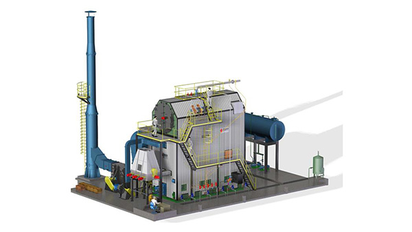
Wade Zhang

CEO of Taishan Group Taian Boao International Trade Co., Ltd. 30 years experience in Global industrial boiler market,  Over 300 boiler projects experience, including 21+ EPC projects. Projects span 30+ countries & regions, involving industries such as nuclear power, energy & electricity, municipal heating, mining, textiles, tires etc.

Key Factors Influencing Heat Transfer and Combustion Efficiency in Industrial Coal-Fired Boilers Read More »

Environmental and Emission Regulations Impacting Industrial Steam Boiler Selection

Environmental and Emission Regulations Impacting Industrial Steam Boiler Selection

In an era of tightening environmental policies and growing climate accountability, environmental and emission regulations are now among the most critical factors influencing the selection of industrial steam boilers. These regulations not only govern the types and levels of pollutants a boiler can emit but also impact decisions about fuel type, burner design, flue gas treatment, monitoring equipment, and long-term operational strategies. Failing to comply with local or international emission standards can result in fines, permit delays, legal penalties, and costly retrofits.

Environmental and emission regulations impact industrial steam boiler selection by setting strict limits on pollutants such as nitrogen oxides (NOx), sulfur oxides (SOx), carbon monoxide (CO), carbon dioxide (CO₂), particulate matter (PM), and volatile organic compounds (VOCs). These requirements influence decisions on fuel sources, combustion technologies, emission control systems (like SCR, ESP, FGD), boiler sizing, and the necessity of continuous emissions monitoring (CEMS). Regulatory bodies such as the U.S. EPA, EU IED, and national environmental agencies enforce these standards through permits and compliance reporting.

Understanding and designing for regulatory compliance from the start ensures that your boiler investment remains viable, legal, and sustainable.

What Are the Key Regulated Emissions for Industrial Steam Boilers?

Industrial steam boilers are critical to sectors like power generation, textiles, paper, chemicals, and food processing. However, these boilers are also significant sources of air pollutants, especially when burning coal, oil, biomass, or waste fuels. To minimize environmental and public health risks, most countries enforce strict emission limits on specific pollutants released from the boiler stack. Understanding which emissions are regulated—and why—is essential for designing compliant systems, selecting the right fuel and technology, and implementing effective emission control strategies.

The key regulated emissions for industrial steam boilers include nitrogen oxides (NOₓ), sulfur oxides (SOₓ), particulate matter (PM), carbon monoxide (CO), carbon dioxide (CO₂), volatile organic compounds (VOCs), and heavy metals such as mercury (Hg). These pollutants are regulated due to their roles in smog formation, acid rain, climate change, respiratory illness, and environmental toxicity. Emission limits vary by country, fuel type, boiler capacity, and regulatory framework, but all require continuous or periodic monitoring and control.

Compliance with emission regulations is a legal obligation and a foundation of sustainable boiler operation.

Industrial steam boilers are regulated for emissions such as NOx, SOx, PM, CO, CO2, and mercury.True

These pollutants have serious health and environmental impacts and are subject to strict national and international emission standards.


🔍 Overview of Key Regulated Boiler Emissions

PollutantFull NamePrimary ConcernMajor Sources
NOₓNitrogen OxidesGround-level ozone (smog), lung irritationHigh-temp combustion
SOₓSulfur OxidesAcid rain, metal corrosionSulfur in fuel (coal, oil, biomass)
PMParticulate MatterRespiratory disease, haze, equipment foulingAsh, soot, unburned fuel
COCarbon MonoxideToxic gas, incomplete combustionPoor combustion control
CO₂Carbon DioxideGreenhouse gas, climate changeCombustion of all carbon-based fuels
VOCsVolatile Organic CompoundsSmog formation, toxic exposureOrganic compounds in some fuels
HgMercuryNeurotoxin, bioaccumulation in ecosystemsTrace in coal and biomass

Each pollutant is regulated for a specific health or environmental reason.


📏 Typical Emission Limits by Region (mg/Nm³)

PollutantEU IEDUS EPA MACTIndia CPCBChina GB13271
NOₓ150–200180–250300–450200–300
SOₓ150–200250100–600200–400
PM10–2025–3030–5020–30
CO100–150150100–200100–150
Hg0.03–0.050.001–0.002Not specified0.03–0.05
CO₂Regulated by carbon market or taxClimate programsPAT scheme (intensity-based)Carbon ETS (pilot)

→ Standards vary based on fuel (e.g., coal, gas, biomass), boiler size, and load.


🛠 Pollutant-Specific Emission Control Technologies

PollutantCommon Control MethodsEfficiency (%)
NOₓLow-NOx burners, SNCR, SCR50–95%
SOₓFGD (wet/dry), limestone injection80–98%
PMESP, baghouse, multicyclone95–99.9%
COBurner tuning, air-fuel ratio controlUp to 90%
CO₂Efficiency improvement, CCS (emerging)5–90% (CCS)
HgActivated carbon injection (ACI), baghouse80–95%

→ Most compliant boilers use multi-layered systems to address all regulated emissions simultaneously.


📊 Example: Emission Profile of a 10 TPH Biomass Boiler (Wood Chips)

PollutantUncontrolled (mg/Nm³)Controlled (mg/Nm³)Compliance with CPCB Norms?
NOₓ420250✅ Yes
SOₓ280180✅ Yes
PM12028✅ Yes
CO300130✅ Yes

→ Achieved using SNCR, bag filter, and O₂ trim system.


🔍 Monitoring Requirements for Regulated Emissions

PollutantMonitoring FrequencyMonitoring Tool
NOₓ, SOₓ, COContinuous (CEMS required)Infrared or chemiluminescence analyzers
PMContinuous or periodicOpacity monitor, gravimetric sampler
CO₂Continuous or calculatedFlow-based GHG calculators, CEMS extension
HgContinuous (in US/EU), periodic elsewhereSorbent traps, mercury CEMS
VOCsPeriodicGC-FID analyzers, flame ionization detector

→ CEMS (Continuous Emissions Monitoring Systems) are mandatory in most jurisdictions for large boilers.


🧪 Real-World Case Study – Industrial Steam Boiler Compliance in China

  • Boiler: 20 TPH coal-fired

  • Issue: PM and SO₂ exceedances during audit

  • Solutions:

    • Installed baghouse for PM <30 mg/Nm³

    • Upgraded to wet FGD system

    • Burner tuning to reduce NOₓ below 250 mg/Nm³

  • Result:

    • Full compliance with GB13271-2014

    • Permit retained, eligible for tax incentives

    • CO₂ emission intensity reduced by 7.2%


🛠 Engineering Considerations for Emission Compliance

Design DecisionEmission Impact
Fuel Type (coal vs. biomass)High-S or high-ash fuels = more SOx/PM
Combustion SystemLow-NOx burner reduces NOx formation
Heat Recovery & EfficiencyLower CO₂ emissions per unit of output
Post-Combustion ControlsEssential to meet tight PM and Hg limits

Choosing a compliant boiler is as much about emission management as it is about steam output.


In conclusion, industrial steam boilers must control and monitor a specific set of emissions—including NOₓ, SOₓ, PM, CO, CO₂, VOCs, and Hg—to comply with environmental regulations and protect public health. These emissions are tightly regulated due to their toxic, corrosive, or climate-changing properties. For plant operators and engineers, emission management is no longer optional—it is integral to design, operation, and long-term viability of industrial steam systems.

Which Global and Regional Environmental Regulations Apply to Steam Boiler Systems?

As industrial steam boilers continue to serve critical roles across sectors like manufacturing, power, and process industries, they are also major sources of air pollutants. Governments around the world enforce strict environmental regulations to control emissions from these systems. These rules differ by region, but they all aim to limit pollutants such as NOₓ, SOₓ, PM, CO, CO₂, and toxic metals through technology mandates, emission thresholds, and continuous monitoring requirements. Whether you’re operating a coal-fired, gas-fired, oil-fired, or biomass boiler, understanding and adhering to these frameworks is essential for permit approval, legal operation, and long-term environmental compliance.

Steam boiler systems are subject to various global and regional environmental regulations, including the European Union’s Industrial Emissions Directive (EU IED), the U.S. EPA’s National Emission Standards for Hazardous Air Pollutants (NESHAP/MACT), China’s GB13271 emission standard, and India’s CPCB 2017 boiler norms. These regulations mandate limits on pollutants such as NOₓ, SOₓ, PM, and CO₂, require emissions monitoring, and often specify allowable fuels and combustion technologies. Compliance is necessary for operating permits, environmental certifications, and avoidance of penalties.

Global boiler regulation is no longer just about emissions—it’s about climate alignment, fuel selection, and technology readiness.

Steam boiler systems are regulated under international and national emission standards depending on region and fuel type.True

Laws like the EU IED, US EPA MACT, and India's CPCB norms mandate emission limits, control technologies, and monitoring requirements for steam boilers.


🌍 Key Global and Regional Environmental Regulations for Steam Boilers

Regulation/AgencyRegionKey Focus
EU IED (2010/75/EU)European UnionIntegrated emission limits for SOₓ, NOₓ, PM, and CO₂; BAT-based approach
BREF for LCPEUBest Available Techniques for Large Combustion Plants (>50 MWth)
US EPA MACT (Boiler Rule)United StatesHazardous air pollutants (HAPs), NOₓ, SO₂, PM; applies to major and area sources
China GB13271-2014ChinaEmission limits for pollutants from stationary sources, tailored by fuel and size
India CPCB 2015 & 2017IndiaPM, NOₓ, SOₓ limits by capacity, age, and location of boilers
South Africa AQASouth AfricaAir Quality Act governs industrial emissions including boilers
ISO 14001 / GHG ProtocolGlobal (voluntary)Environmental and climate disclosure frameworks including boiler GHG emissions

📏 Emission Limits in Major Jurisdictions (mg/Nm³ unless noted)

RegionPM (mg/Nm³)NOₓ (mg/Nm³)SO₂ (mg/Nm³)CO (mg/Nm³)Hg (µg/Nm³)CEMS Required
EU (IED)≤10–30≤150–200≤150≤100≤30Yes
USA (EPA MACT)≤20–30≤180–250≤250≤150≤5Yes
China (GB13271)≤20–30≤300≤200–400≤100–150≤30Yes (≥10 TPH)
India (CPCB 2017)≤30–50≤300–450≤100–600≤150–200Not SpecifiedYes (≥10 TPH)

→ Regulations differ by fuel type (coal, gas, biomass) and boiler capacity (e.g., <10 TPH vs. >50 MWth).


🛠 Technologies Mandated or Encouraged by Regulation

RegulationTechnology Encouragements or Mandates
EU IED / BREFLow-NOx burners, SCR/SNCR, ESP or baghouse, FGD, energy recovery
EPA MACT (USA)PM control (ESP/baghouse), Hg capture (ACI), combustion tuning
China GB13271CEMS, SNCR, ash handling, desulfurization systems
India CPCB 2017SNCR/SCR, bag filter/ESP, O₂ monitoring, wet scrubber

Non-compliant plants risk penalties, shutdowns, or revocation of environmental clearance.


📊 Real-World Example – Regulation-Driven Upgrade (India)

Project ComponentBefore Regulation (2015)After CPCB 2017 Compliance
Boiler Size35 TPH Coal-FiredSame
PM Emissions95 mg/Nm³28 mg/Nm³ (Baghouse installed)
NOₓ ControlNoneSNCR with urea dosing system
SO₂ ControlLime injection addedEmissions <450 mg/Nm³
MonitoringManual logbookCEMS integrated with CPCB
ResultLegal compliance, GHG reduction credits unlocked 

→ Ensured permit renewal and alignment with ESG targets.


📈 Penalties and Incentives in Global Boiler Regulation

RegionNon-Compliance PenaltiesCompliance Incentives
EUFines, shutdown, denial of permit renewalsCarbon trading eligibility, green financing
USAEPA fines ($25,000+/day), injunctive reliefENERGY STAR and tax credits
ChinaPublic violation notices, production haltsPreferential electricity pricing
IndiaCPCB closure notices, fines, legal actionPAT scheme energy savings certificates
South AfricaEmission tax, criminal chargesCarbon offset mechanisms

→ Environmental compliance is not just about avoiding penalties—it opens doors to incentives.


🌐 Alignment with Global Climate and ESG Frameworks

Global FrameworkRelevance to Boiler Emissions
UNFCCC / Paris AgreementTargets CO₂ and GHG reduction
ISO 14001Environmental management system certification
SBTi (Science-Based Targets)Requires scope 1 emissions reduction (including boilers)
GHG Protocol (Scope 1)Boiler CO₂ and CH₄ emissions are reportable
CDP Climate DisclosureCompanies must report industrial combustion emissions

Boiler systems must now fit into corporate decarbonization plans and ESG disclosures.


🧪 Compliance Roadmap for Boiler Projects

StepAction
Step 1Identify applicable national regulations
Step 2Assess boiler fuel type, size, and age
Step 3Conduct emission audit or baseline study
Step 4Retrofit or design appropriate control systems
Step 5Install CEMS and set up reporting to regulators
Step 6Align with ESG/climate reporting obligations

Early alignment reduces compliance risk and improves long-term operational resilience.


In conclusion, steam boilers are subject to a variety of global and regional environmental regulations that govern their emissions, fuel types, and monitoring systems. Whether you’re operating in Europe, the U.S., Asia, or Africa, staying compliant requires a thorough understanding of applicable laws and integrating emission control technologies accordingly. Beyond avoiding penalties, regulatory compliance offers access to carbon markets, green finance, and reputational value in today’s climate-conscious economy.

How Do Fuel Type and Burner Design Affect Regulatory Compliance?

Fuel type and burner design are not just technical variables—they’re core determinants of regulatory compliance in industrial boiler systems. From particulate matter in coal combustion to nitrogen oxides in gas burners, different fuels inherently produce different emissions. The burner’s ability to mix air and fuel, control flame temperature, and promote complete combustion plays a critical role in limiting these emissions. Regulatory agencies worldwide impose specific pollutant limits that vary based on fuel source and combustion technology, making the right fuel-burner combination essential for legal operation and emissions control.

Fuel type and burner design directly impact regulatory compliance by determining the quantity and type of pollutants emitted during combustion. Fuels such as coal and biomass produce higher PM and SOx, requiring more advanced emission controls, while gas emits lower PM but more NOx under high-temperature flames. Burner design affects how efficiently fuel burns, influencing CO, NOx, and unburned hydrocarbons. A mismatch between fuel characteristics and burner capability can lead to regulatory exceedances, permit violations, and penalties.

In modern boiler systems, compliance starts at the fuel feeder and burner nozzle—not just the stack.

Fuel type and burner design directly impact emission levels and regulatory compliance.True

Different fuels emit different pollutants, and burner design affects how completely and cleanly the fuel burns, which in turn determines whether emission standards are met.


🔍 How Fuel Type Influences Emission Profiles

Fuel TypePMNOxSOxCOHgCO₂
CoalHighMedium–HighHighMediumHighHigh
BiomassMedium–HighMediumLow–MediumMediumLowNeutral–Medium
Natural GasVery LowHigh (thermal NOx)NegligibleLowNegligibleMedium
Fuel OilMediumMedium–HighMedium–HighMediumMediumHigh
Waste Fuels (RDF)HighVariableVariableHighHighHigh

→ Regulatory requirements are stricter for dirtier fuels due to their pollutant load.


🔧 Burner Design Features That Influence Compliance

Burner FeatureEmission ImpactRelevance to Regulation
Air-Fuel MixingAffects CO, PM, VOCsPoor mixing = high CO, visible smoke
Flame Temperature ControlAffects NOx formationLower flame temp = less thermal NOx
Atomization (for liquids)Affects combustion completenessFine droplets = less unburned fuel
Swirl/Staging DesignImproves combustion stability and burnoutHelps meet low-NOx targets
Turn-Down RatioSupports stable combustion at low loadsPrevents CO and cycling-related emissions

→ Burners must be designed or tuned to match fuel combustion characteristics for compliance.


📏 Region-Specific Fuel and Burner Regulations (Examples)

RegionFuel-Based RegulationBurner/Technology Requirement
EU (IED)Fuel-specific BAT limits for NOx, SOx, PMRequires low-NOx burners, staged combustion
USA (EPA MACT)HAP limits for solid/liquid/gas boilersBurner tuning, O₂ control, PM filters
China (GB13271)Differentiated limits for biomass, coal, gasBurner and CEMS verification
India (CPCB 2017)Limits by fuel and boiler sizeBurner optimization + emission control tech

Non-compliance can result in denied permits, operational shutdowns, or heavy fines.


📊 Example – Burner-Fuel Pairing and Compliance Risk

Fuel + Burner SetupPM (mg/Nm³)NOx (mg/Nm³)CO (ppm)Regulatory Status
Coal + basic burner (no staging)120420250❌ Exceeds limits
Biomass + stoker + bag filter28260140✅ Compliant
Natural Gas + low-NOx burner712035✅ Compliant
HFO + pressure jet burner45320180⚠ Requires scrubber

→ Even clean fuels like gas require correct burner design to control NOx emissions.


🛠 Matching Fuel and Burner for Compliance Success

Fuel TypeRecommended Burner TypeRequired Controls for Compliance
CoalPulverized coal burner or CFBESP/baghouse, FGD, low-NOx design
BiomassMoving grate or FBCMulticyclone or fabric filter, staged air
GasLow-NOx premix or staged burnerO₂ trim, flue gas recirculation (FGR)
Fuel OilAir or steam-atomized burnerSCR/SNCR, soot blowers, CO tuning
Waste RDFRotary kiln or hybrid burnerACI for Hg, high-temp staging, baghouse

Correct pairing ensures regulatory compliance and stable boiler operation.


🧪 Real-World Case – Compliance Upgrade via Burner Retrofit

  • Plant: 15 TPH biomass boiler

  • Problem: NOx > 400 mg/Nm³, CO > 200 ppm

  • Root Cause: Inadequate air-fuel mixing in stoker burner

  • Solution:

    • Replaced with staged combustion burner

    • Added O₂ sensor for trim control

    • Installed bag filter for PM

  • Result:

    • NOx reduced to 230 mg/Nm³

    • CO reduced to 80 ppm

    • Achieved full CPCB 2017 compliance

    • Efficiency improved by 4.2%


📈 Burner-Fuel Design Checklist for Emission Compliance

Design AreaCompliance Function
Fuel Analysis (CV, moisture, ash)Informs burner air-fuel matching
Burner Air StagingControls NOx and CO
Flame Shape OptimizationEnsures full burnout
Atomization Type (for oils)Prevents soot and CO formation
Burner Control IntegrationReal-time efficiency and emission feedback

→ Compliance is achieved not by emission controls alone—but by engineering combustion correctly.


In conclusion, fuel type and burner design are foundational to regulatory compliance in steam boiler systems. Each fuel presents unique combustion and emission challenges, and burner performance determines whether those challenges are managed effectively. Choosing the right burner for your fuel—and maintaining optimal air-fuel mixing and flame control—is essential not just for efficiency, but for legal and environmental integrity. In modern boiler operations, compliance starts with combustion.

What Emission Control Technologies Are Required to Meet NOx, SOx, and PM Limits?

Industrial steam boilers, particularly those firing solid and liquid fuels, are significant point sources of air pollutants such as nitrogen oxides (NOx), sulfur oxides (SOx), and particulate matter (PM). These emissions are tightly regulated across the globe due to their harmful effects on human health, air quality, and ecosystems. Achieving compliance with regional and international emission standards requires the deployment of dedicated flue gas cleaning systems—each tailored to control specific pollutants. Selection of appropriate emission control technologies depends on fuel type, combustion method, stack flow rates, and regulatory limits.

To meet emission limits for NOx, SOx, and PM in industrial boiler systems, a combination of Selective Catalytic Reduction (SCR) or Selective Non-Catalytic Reduction (SNCR) for NOx, Flue Gas Desulfurization (FGD) systems for SOx, and Electrostatic Precipitators (ESP) or fabric filters (baghouses) for PM is typically required. These technologies are often used in series to ensure each pollutant is captured before discharge, ensuring compliance with EU, US EPA, India CPCB, and China GB13271 regulations.

Each component plays a vital role in delivering a clean, regulation-compliant exhaust stream.

Emission control technologies like SCR, FGD, and ESP are required to meet NOx, SOx, and PM limits in industrial boilers.True

These technologies are designed to remove specific pollutants and are often required by law to meet regional and international air quality standards.


🔍 Overview of Primary Emission Control Technologies

PollutantControl TechnologyRemoval Efficiency (%)Common Application
NOxSNCR (urea or ammonia injection)30–60%Biomass, coal, oil
 SCR (catalyst-based)80–95%Natural gas, coal
SOxDry FGD (lime injection)70–90%Biomass, RDF
 Wet FGD (limestone slurry)90–98%Coal, oil
PMElectrostatic Precipitator (ESP)95–99.5%Coal, biomass
 Baghouse (Fabric Filter)98–99.9%Biomass, RDF, waste

→ Systems are often combined into multi-stage pollution control trains.


📊 Example – Flue Gas Cleaning System for a 30 TPH Coal Boiler

EmissionRaw Stack LevelControl Tech UsedFinal EmissionRegulation Met?
NOx420 mg/Nm³SNCR (urea)210 mg/Nm³✅ (EU < 200, India < 300)
SOx520 mg/Nm³Wet FGD80 mg/Nm³✅ (All regions)
PM110 mg/Nm³ESP28 mg/Nm³✅ (India < 30)

→ Final stack emissions fully compliant with CPCB, EU IED, and China GB13271 norms.


🛠 NOx Control Technologies: SNCR vs. SCR

FeatureSNCRSCR
ProcessUrea or ammonia injected into furnaceSame reagent passed through catalyst bed
Temp. Range850–1100°C300–400°C
Reduction Efficiency30–60%80–95%
CostLower CAPEXHigher CAPEX + OPEX
Fuel CompatibilityBiomass, coal, oilGas, coal, oil
MaintenanceModerateCatalyst inspection/replacement

→ SCR preferred in gas-fired and high-efficiency plants.


💨 SOx Control Technologies: FGD Systems

TechnologyTypeKey Features
Wet FGDLimestone slurryMost effective, high SO₂ absorption (>95%)
Dry FGDHydrated lime injectionSimpler, used for smaller units
Semi-dry FGDAtomized lime sprayHybrid between wet and dry, 85–90% removal
In-furnace DesulfurizationLimestone with fuelLower efficiency (~50–60%)

FGD systems are essential for high-sulfur fuels like coal or petcoke.


🌫 PM Control Technologies: ESP vs. Baghouse

FeatureESPBaghouse
Collection MethodElectrostatic chargeMechanical filtration
Efficiency95–99.5%98–99.9%
Fuel Type SuitabilityCoal, biomassHigh-ash, variable-fuel blends
Sensitivity to MoistureYesLess affected
MaintenanceLower filter change rateRequires periodic bag replacement

→ Baghouses are preferred for biomass and waste with variable ash content.


📏 Global Emission Limits Driving Control Technology Use

RegionNOx (mg/Nm³)SOx (mg/Nm³)PM (mg/Nm³)CEMS RequiredControl Tech Expectation
EU (IED)≤200≤150≤10–30YesSCR, FGD, baghouse/ESP
USA (MACT)≤180–250≤250≤20–30YesSCR or SNCR, FGD, ESP
China GB13271≤300≤400≤20–30YesSNCR, semi-dry FGD, baghouse
India CPCB≤300–450≤100–600≤30–50YesSNCR, dry FGD, ESP

→ Each region imposes strict requirements, influencing boiler and emissions system design.


🧪 Real-World Upgrade: 20 TPH Biomass Boiler (India CPCB 2017 Compliance)

  • Problem: PM = 90 mg/Nm³, NOx = 430 mg/Nm³

  • Actions Taken:

    • Installed baghouse filter → PM < 28 mg/Nm³

    • Added SNCR with urea dosing → NOx = 220 mg/Nm³

    • Implemented oxygen trim and CO monitoring

  • Result:

    • Full regulatory compliance

    • Improved boiler efficiency by 5.2%

    • Reduced CO₂ intensity by 6.7%


📈 Integrated Emission Control Strategy for Modern Boilers

Control StageTarget PollutantTechnology Used
Combustion OptimizationCO, NOxBurner tuning, O₂ trim
In-furnace ControlNOx, SOxStaged air, limestone injection
Flue Gas ConditioningSOx, PMFGD, ammonia injection
Final Particulate CapturePMESP or bag filter
Continuous MonitoringAllCEMS and DAHS

→ A layered approach ensures legal compliance and operational reliability.


In conclusion, emission control technologies such as SCR/SNCR, FGD systems, and ESPs or baghouses are essential to meet NOx, SOx, and PM limits in industrial steam boiler systems. Each technology targets a specific pollutant and must be selected based on fuel characteristics, local regulations, and boiler capacity. In today’s regulatory environment, emission control is not optional—it is a critical design and operational requirement for any responsible and future-ready steam generation system.

Why Is Continuous Emissions Monitoring (CEMS) Essential for Compliance?

Environmental regulations for steam boiler systems are becoming increasingly stringent across the globe. Simply installing pollution control equipment is no longer enough—regulators demand proof that emission limits are being met at all times. This is where Continuous Emissions Monitoring Systems (CEMS) come into play. These systems provide real-time, continuous data on pollutant emissions directly from the stack, ensuring accurate reporting, early warning of deviations, and robust evidence for compliance audits. Without CEMS, plants face a higher risk of violations, penalties, or permit rejections due to incomplete or inaccurate emissions reporting.

Continuous emissions monitoring (CEMS) is essential for regulatory compliance because it provides real-time, verifiable, and continuous data on key pollutants like NOx, SOx, CO, CO₂, and PM. It ensures that emissions remain within permitted limits, supports mandatory reporting to environmental authorities, detects control system failures early, and proves compliance during audits. Many regions—including the EU, USA, China, and India—require CEMS by law for medium to large-capacity boilers.

In modern environmental governance, “If you didn’t measure it, you didn’t comply.”

CEMS is essential for emissions compliance in regulated industrial boiler systems.True

It provides continuous, accurate, and verifiable data on pollutant emissions, which is required by most environmental authorities for legal operation and auditing.


🔍 What Does a CEMS Monitor?

PollutantWhy It’s MonitoredRegulatory Threshold Examples (mg/Nm³)
NOxContributes to smog and ozoneEU ≤ 150, India ≤ 300, China ≤ 300
SOxCauses acid rainEU ≤ 150, India ≤ 100–600
COIndicates incomplete combustionEU ≤ 100, US ≤ 150
CO₂Climate regulation, carbon marketsVaries (GHG intensity limits, carbon tax)
PMRespiratory hazardEU ≤ 10–30, India ≤ 50
O₂Required for combustion control validationTarget range: 3–6%
OpacityVisual emissions indicatorOften required in coal or waste boilers

→ CEMS ensures pollutants are continuously below limits—not just during annual inspections.


🛠 Components of a Typical CEMS Setup

ComponentFunction
Gas Sampling ProbeExtracts flue gas from stack
Sample Conditioning UnitRemoves particulates, moisture, and cools sample
AnalyzersMeasure NOx, SOx, CO, CO₂, O₂, VOCs, etc.
Data Acquisition System (DAHS)Stores, formats, and transmits data
Stack Opacity MonitorMonitors visible emissions (PM proxy)

→ CEMS is often integrated with SCADA or PLC systems for automated control and alerting.


📏 Regulatory Requirements for CEMS

RegionCEMS MandateParameters Required
EU IEDRequired for >50 MWthNOx, SO₂, CO, CO₂, PM, O₂
US EPA (40 CFR Part 60 & 75)Required for major sources (>25 MMBtu/hr)NOx, SOx, CO, CO₂, Hg, Opacity
India CPCB 2017Mandatory for boilers ≥10 TPHPM, NOx, SOx, CO, O₂
China MEERequired for all industrial boilers >10 TPHNOx, SOx, PM, CO, O₂

→ Missing or faulty CEMS can lead to permit suspension or environmental penalties.


📊 Example – Compliance Dashboard from CEMS

ParameterMeasured ValueLimitStatus
NOx198 mg/Nm³250✅ OK
SOx158 mg/Nm³300✅ OK
PM28 mg/Nm³50✅ OK
CO180 ppm200✅ OK
O₂4.2%3–6%✅ Optimal

→ These readings are stored in the DAHS and transmitted to the environmental authority portal.


🎯 Benefits of CEMS for Regulatory and Operational Compliance

BenefitDescription
Regulatory ReportingEnables real-time submission to pollution control boards
Audit ReadinessHistorical data proves continuous compliance
Early Fault DetectionAlerts on spikes in CO, NOx, or O₂ deviation
Control System FeedbackReal-time input for SNCR, FGD, or burner adjustment
Avoids Manual ErrorsEliminates gaps and inaccuracies from manual logs
Supports Carbon AccountingValidates CO₂ footprint and ESG disclosures

Plants without CEMS are often flagged as non-transparent or high-risk operations.


🧪 Real-World Case Study – Biomass Boiler (India, CPCB CEMS Mandate)

  • Boiler: 12 TPH stoker-fired biomass

  • Compliance Risk: Manual PM reporting flagged as non-conforming

  • Solution:

    • Installed multi-gas CEMS + opacity meter

    • Integrated with local CPCB online monitoring portal

    • Configured alert limits for NOx and CO exceedance

  • Outcome:

    • 24/7 data compliance

    • PM reduced to 25 mg/Nm³

    • Secured pollution clearance renewal + ISO 14001 audit pass


🛑 Risks of Not Using CEMS

RiskConsequence
Non-complianceFines, shutdowns, denial of permit
Emission Spikes Go UndetectedLegal liability and community health risk
Audit FailureLost certifications (ISO, ESG, etc.)
Manual Data TamperingPenalties under environmental protection acts

→ Increasingly, CEMS is not optional—it’s mandatory for medium-to-large industrial boilers.


In conclusion, Continuous Emissions Monitoring Systems (CEMS) are essential tools for ensuring real-time regulatory compliance in steam boiler operations. By automatically measuring and reporting key pollutants, CEMS provides transparency, accountability, and legal assurance. As environmental laws tighten globally, having CEMS is no longer just a best practice—it’s a compliance cornerstone.

How Can Regulatory Foresight Help Future-Proof Your Boiler Selection?

Choosing an industrial boiler isn’t just an engineering decision—it’s a long-term business commitment. While today’s models may meet current emissions requirements, regulations evolve rapidly due to tightening environmental laws, carbon targets, and public health priorities. If your boiler cannot adapt to future standards, you may face unexpected upgrade costs, operational restrictions, or even forced retirement. This is where regulatory foresight becomes essential. It enables plant designers, procurement teams, and owners to anticipate emerging rules, integrate flexibility into system design, and choose technologies that will remain compliant for decades—not just today.

Regulatory foresight helps future-proof boiler selection by anticipating upcoming emissions standards, carbon policies, and fuel restrictions, allowing plant owners to choose adaptable systems that can meet both current and future environmental requirements. This proactive approach reduces the risk of compliance violations, costly retrofits, stranded assets, and missed opportunities in carbon markets. Boilers selected with foresight incorporate features like modular control systems, flexible fuel compatibility, and space for future emission controls.

Without it, today’s investment can become tomorrow’s liability.

Regulatory foresight allows companies to select boiler systems that remain compliant as emissions and carbon standards evolve.True

Anticipating future regulations ensures boilers are equipped or upgradeable to meet long-term legal and environmental requirements.


🔍 Key Regulatory Trends That Influence Boiler Selection

Regulatory DriverEmerging RequirementImpact on Boiler Selection
Decarbonization TargetsCO₂ caps, carbon pricing, ETSFavor high-efficiency or low-carbon fuel boilers
Stricter NOx and PM LimitsLower thresholds in urban or non-attainment zonesRequire low-NOx burners, bag filters
CEMS MandatesReal-time emissions trackingMust include space and ports for sensors
Fuel Use RestrictionsCoal bans, biomass limits, fossil fuel phaseoutsRequire fuel flexibility or alternative energy integration
Green Certification (ISO, ESG)Scope 1 emissions disclosure, lifecycle impactLow-carbon design and monitoring-ready systems

Ignoring these trends can lead to early obsolescence and non-compliance penalties.


📏 Comparing Short-Term vs. Future-Proof Boiler Choices

Boiler FeatureShort-Term FocusedFuture-Proof Focused
NOx ControlBasic burnerLow-NOx or staged combustion system
Fuel FlexibilityDesigned for single fuelMulti-fuel compatible (biomass, RDF, gas)
Emission MonitoringManual or spot measurementCEMS-ready with data integration
Carbon ManagementNo CO₂ trackingGHG-calibrated, net-zero alignment
Upgrade CapabilityFixed configurationModular design for later retrofits

→ Future-proofing is not about maximum capacity, but about maximum adaptability.


🛠 Key Features to Include in a Future-Ready Boiler Design

Design ConsiderationLong-Term Benefit
High Turndown BurnerHandles fluctuating loads with low emissions
Integrated or Allowance for SCR/SNCRReady for NOx limit tightening
Space for Baghouse or ESPAllows PM compliance as norms tighten
Stack Ports for CEMSEnables quick compliance setup
Hybrid Fuel SystemSupports fossil-to-biomass or gas transitions
Condensing EconomizerImproves CO₂ efficiency
Smart Boiler ControlsEnables auto-compliance with O₂ trim and alerts

These features ensure compliance without future retrofit disruption.


📊 Example – Cost Impact of Reactive vs. Proactive Selection

ScenarioReactive (Upgrade Required)Proactive (Future-Proof Boiler)
Initial Boiler Cost$850,000$1,000,000
Retrofit for NOx Compliance$180,000 (SCR)Included
Bag Filter Installation$120,000Pre-installed
Lost Production (downtime)5 days0 days
Compliance Status (2028)⚠ Risk of violation✅ Fully compliant
Net 10-Year Cost$1.2M+$1.0M

→ The proactive choice costs less over time and ensures regulatory continuity.


🧪 Case Study: Biomass Boiler – Future-Ready Investment

  • Sector: Food processing

  • Boiler Type: 10 TPH multi-fuel fluidized bed

  • Foresight Applied:

    • Integrated ports for CEMS and CO₂ tracking

    • SCR mounting flanges included

    • Space allocated for future baghouse

    • Fuel system designed to switch from rice husk to wood pellets

  • Result:

    • CPCB 2017 compliant from start

    • Avoided $250,000 in upgrades after state PM limits reduced

    • Qualified for renewable energy credit in India’s PAT scheme


📈 Global Regulations Likely to Tighten (Next 5–10 Years)

RegionExpected Regulatory ChangeForesight-Driven Response
EUCO₂ intensity reduction, tighter NOx in urban zonesChoose low-NOx condensing gas boiler
USAExpanded MACT for area sources, carbon reportingSelect SCR-ready boiler + DAHS integration
ChinaPM tightening in eastern provincesPrefer baghouse over ESP
IndiaUrban NOx zones, biomass restrictionsAvoid stoker-type, use low-NOx FBC

Select now what regulations will demand later.


🎯 Strategic Boiler Selection Roadmap

StepAction
1. Regulatory ScanReview national and local emissions forecasts
2. Fuel Future AssessmentEvaluate fuel availability and policy trends
3. Tech Flexibility AuditChoose boilers with upgrade and control options
4. CO₂ and GHG PlanningSelect systems compatible with carbon frameworks
5. Permit Future-ProofingInclude space and layout for control system expansion

A future-proof boiler selection strategy aligns with engineering, regulatory, and ESG goals.


In conclusion, regulatory foresight is a powerful tool for making boiler selection decisions that stand the test of time. By anticipating how emissions, carbon, and reporting rules will evolve, you can invest in systems that adapt with minimal disruption and maximum ROI. Rather than react to each new regulation with costly retrofits, smart boiler owners design with the future in mind—ensuring long-term compliance, efficiency, and environmental responsibility.

🔍 Conclusion

Environmental and emission regulations are no longer an afterthought—they are a defining element of industrial steam boiler selection. From initial design to long-term operation, every decision must be made with compliance in mind. A properly selected, regulation-compliant boiler system not only helps you avoid costly penalties but also supports your sustainability goals, operational efficiency, and public reputation in today’s environmentally conscious world.


📞 Contact Us

💡 Need expert support selecting a steam boiler that meets environmental regulations? We specialize in low-emission boiler system design, regulatory consulting, and turnkey installation for a wide range of industrial sectors.

🔹 Reach out today and build an environmentally compliant steam boiler system with confidence! ♨️🌍✅

FAQ

What environmental regulations apply to industrial steam boilers?

Industrial steam boilers must comply with regulations such as the U.S. EPA Clean Air Act, EU Industrial Emissions Directive (IED), and various regional air quality regulations. These set strict limits on NOx, SO₂, CO₂, particulate matter (PM), and CO emissions, directly impacting boiler design and fuel choices.

Why is NOx regulation significant for steam boilers?

Nitrogen oxides (NOx) are tightly regulated due to their role in smog and acid rain. Compliance may require the use of low-NOx burners, flue gas recirculation (FGR), or selective catalytic reduction (SCR) systems to keep emissions within legal limits.

How do SO₂ and fuel sulfur content influence boiler design?

Steam boilers burning high-sulfur fuels like coal or heavy oil must include flue gas desulfurization (FGD) systems such as wet scrubbers or use low-sulfur fuels to reduce SO₂ emissions in compliance with air quality standards.

What technologies are used to control particulate emissions in steam boilers?

Particulate matter, especially PM2.5 and PM10, is controlled using cyclone separators, electrostatic precipitators (ESPs), or baghouse filters. These are crucial in solid-fuel and biomass-fired steam boilers.

How do greenhouse gas (GHG) regulations affect steam boiler selection?

To reduce CO₂ emissions, steam boilers must meet efficiency standards and may be required to integrate condensing technology, use renewable fuels, or support carbon capture systems. Some regions offer incentives for using biomass or cleaner fuels.

References

  1. EPA Industrial Boiler Regulationshttps://www.epa.gov

  2. EU Industrial Emissions Directive (IED)https://www.europa.eu

  3. NOx Control Guidelines for Steam Boilershttps://www.sciencedirect.com

  4. SO₂ Emissions and Flue Gas Treatmenthttps://www.researchgate.net

  5. Boiler Particulate Control Technologieshttps://www.bioenergyconsult.com

  6. Greenhouse Gas Reduction in Boilershttps://www.mdpi.com

  7. Boiler Emission Compliance Strategieshttps://www.energysavingtrust.org.uk

  8. Steam Boiler Efficiency and CO₂ Impacthttps://www.iea.org

  9. Air Quality and Emission Standards for Industryhttps://www.automation.com

  10. Industrial Boiler Regulations by Fuel Typehttps://www.asme.org
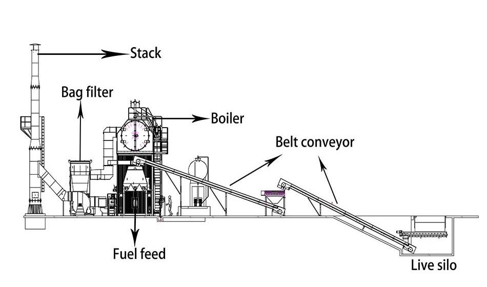
Wade Zhang

CEO of Taishan Group Taian Boao International Trade Co., Ltd. 30 years experience in Global industrial boiler market,  Over 300 boiler projects experience, including 21+ EPC projects. Projects span 30+ countries & regions, involving industries such as nuclear power, energy & electricity, municipal heating, mining, textiles, tires etc.

Environmental and Emission Regulations Impacting Industrial Steam Boiler Selection Read More »

Key Factors Influencing Heat Transfer and Combustion Efficiency in Industrial Oil-Fired Boilers

Key Factors Influencing Heat Transfer and Combustion Efficiency in Industrial Oil-Fired Boilers

For industrial facilities relying on oil-fired boilers, maximizing heat transfer and combustion efficiency is crucial to achieve optimal fuel utilization, lower emissions, and reduced operational costs. However, many operations suffer from hidden losses due to poor combustion control, fouling, or mismatched burner configurations. Without a clear understanding of the factors that influence these efficiencies, boiler performance can decline significantly over time, leading to increased maintenance and energy waste.

The heat transfer and combustion efficiency in industrial oil-fired boilers are influenced by multiple interrelated factors, including burner design, fuel atomization quality, excess air levels, flue gas temperature, soot buildup, and the cleanliness of heat transfer surfaces. Efficient combustion ensures complete fuel burning with minimal unburned carbon or pollutants, while effective heat transfer maximizes the capture of combustion heat by the water or steam system. Poor combustion or heat exchange leads directly to energy losses, higher fuel bills, and reduced boiler life.

Let’s dive into the key factors you must monitor and optimize to keep your oil-fired boiler operating at peak efficiency.

How Does Burner Design and Fuel Atomization Impact Combustion Efficiency?

At the heart of any efficient boiler lies the combustion process—and burner design is the engine of that process. Whether in gas, oil, or biomass systems, the quality of combustion determines how well fuel energy is converted into heat. Poor burner performance doesn’t just reduce efficiency—it leads to fuel waste, excess emissions (like CO and NOₓ), and maintenance headaches. One of the most critical but often overlooked aspects of burner performance is fuel atomization—the way the burner converts fuel into a fine spray for ignition. If atomization is poor, efficiency plummets, no matter how good the boiler or controls are.

Burner design and fuel atomization directly affect combustion efficiency by influencing flame stability, air-fuel mixing, and the completeness of fuel burn. A well-designed burner ensures optimal atomization of liquid fuels or proper mixing of gas and air, creating a uniform flame and high combustion temperature. This minimizes unburnt fuel, lowers CO and particulate emissions, and improves heat transfer—leading to higher boiler thermal efficiency.

In short, efficient combustion begins with precise burner mechanics.

Burner design and fuel atomization affect combustion efficiency by influencing how completely fuel is burned.True

Efficient atomization and mixing allow more thorough combustion, which improves thermal efficiency and reduces emissions.


🔧 How Burner Design Affects Combustion Efficiency

Burner FeatureRole in CombustionEfficiency Impact
Flame Geometry (Shape/Length)Controls heat distribution and furnace absorptionUneven flames can cause poor heat transfer
Air-Fuel Mixing MechanismEnsures all fuel particles contact oxygenPoor mixing leads to unburnt fuel/CO
Turn-Down RatioMaintains combustion quality across load rangesLow turn-down = inefficient low-load burn
Swirl and Recirculation ZonesStabilize flame and promote complete burnHelps reduce NOₓ and improve burnout
Staged Combustion DesignReduces flame temp to minimize NOₓBalances efficiency with emission control

A well-designed burner maintains optimal combustion even during dynamic load changes.


🔬 Fuel Atomization: The Hidden Key to Efficient Burn

What is Atomization?Why It Matters
Breaking liquid fuel into fine dropletsIncreases surface area for vaporization and burning
Occurs at the burner nozzleAffects ignition, flame stability, and emissions
Depends on pressure, temperature, and nozzle designCrucial for oil and biomass slurry fuels

Types of Atomization in Boilers

MethodFuel TypeProsChallenges
Pressure AtomizationDiesel, HFOSimple, no air requiredSensitive to pressure and viscosity
Air AtomizationHFO, waste oilsFine droplets, better mixingNeeds compressed air system
Steam AtomizationHigh-viscosity fuelsGood for heavy fuelsHigh steam consumption
Rotary/MechanicalBiomass slurryUsed in special burnersMaintenance-intensive

→ Poor atomization = fuel droplets burn incompletely, forming CO, soot, and loss of efficiency.


📊 Impact of Atomization Quality on Combustion Efficiency – Example

Atomization QualityCO Emissions (ppm)Unburnt Carbon in Ash (%)Measured Thermal Efficiency (%)
Optimal (Fine Spray)<50<0.587.2
Moderate1201.282.9
Poor (Coarse Spray)2502.578.4

Efficiency loss of nearly 9% caused solely by sub-optimal fuel atomization.


🛠 Real-World Case Study: 10 TPH Heavy Fuel Oil Boiler

  • Problem: Excessive fuel use and high CO emissions

  • Findings:

    • Fuel nozzle clogged → coarse spray

    • Flame irregular and elongated

    • O₂: 4.5%, CO: 280 ppm

  • Solution:

    • Replaced nozzles

    • Upgraded to steam-assisted atomizing system

    • Burner re-tuned with air modulation

  • Result:

    • CO dropped to <60 ppm

    • Thermal efficiency improved from 79.5% to 86.3%

    • Annual fuel savings: $32,000


🔍 Burner Design by Fuel Type – Selection Guide

Fuel TypeRecommended Burner TypeAtomization Requirement
Natural GasLow-NOx premix burnerUniform air-fuel mixing
Diesel / LDOPressure jet burnerFine, stable spray
HFO / Waste OilAir or steam atomizing burnerAdjustable for viscosity/temp
Biomass SlurryRotary atomizing burnerHigh-shear atomization
Pulverized BiomassMulti-fuel burner with swirlFast mixing, staged ignition

Proper burner-fuel matching is essential for combustion efficiency and emission control.


📈 Monitoring and Optimization Tools for Burners

InstrumentPurpose
O₂ + CO Flue Gas AnalyzerMeasures combustion completeness
Infrared ThermographyChecks flame shape and burner symmetry
Atomization Pressure GaugeVerifies nozzle pressure for stable spray
Fuel Viscosity ControllerEnsures correct atomization temp/flow
Burner Management System (BMS)Automates ignition, modulation, and alarms

These tools support diagnostics, tuning, and safety.


In conclusion, burner design and fuel atomization are critical to achieving high combustion efficiency. They ensure complete fuel burnout, minimize pollutant formation, and enable responsive flame control across load ranges. Poor atomization or mismatched burners result in avoidable fuel waste, increased emissions, and unstable operations. For any boiler system—especially oil or biomass-fired—investing in the right burner and maintaining proper atomization is one of the most cost-effective paths to efficiency.

Why Is Maintaining the Correct Air-to-Fuel Ratio Critical for Optimal Combustion?

In any combustion system—whether firing natural gas, oil, coal, or biomass—the air-to-fuel ratio is a decisive factor in efficiency, safety, and emissions control. Too little air leads to incomplete combustion and the formation of carbon monoxide (CO) and soot. Too much air, on the other hand, dilutes the flame, lowers the temperature, and sends valuable heat energy out the stack with the excess oxygen. For boilers, especially, maintaining the optimal air-to-fuel ratio is essential to maximize energy extraction from the fuel while minimizing emissions and fuel costs.

Maintaining the correct air-to-fuel ratio is critical for optimal combustion because it ensures complete fuel burn, maximizes heat release, and minimizes losses through unburned fuel or excess flue gas. Insufficient air causes incomplete combustion, producing CO and particulates, while excessive air cools the flame and increases flue gas heat loss. An optimal ratio improves thermal efficiency, reduces emissions such as CO, NOₓ, and PM, and ensures safe, stable operation of the boiler.

Getting this balance right is one of the most powerful levers to improve boiler performance and environmental compliance.

Maintaining the correct air-to-fuel ratio ensures complete combustion and high thermal efficiency.True

Too much or too little air results in heat loss and unburned fuel, reducing efficiency and increasing emissions.


🔧 Understanding the Stoichiometric and Actual Air-Fuel Ratio

TermDefinition
Stoichiometric RatioExact air needed to chemically burn all fuel (no excess)
Actual Air-Fuel RatioAir actually supplied, often higher than stoichiometric
Excess Air (%)Additional air above stoichiometric to ensure complete burn
O₂ in Flue Gas (%)Common measurement to indicate actual excess air

For example, natural gas requires ~10:1 air-to-fuel ratio by volume for stoichiometric combustion.


📊 Recommended Excess Air Levels by Fuel Type

Fuel TypeStoichiometric AirPractical Excess Air (%)Flue Gas O₂ (%)
Natural Gas~10:15–10%1–3%
Light Fuel Oil~14:110–15%2–4%
Coal / Biomass~10–11:120–40%5–8%

→ These levels ensure complete combustion while minimizing thermal losses.


🔍 What Happens When the Air-to-Fuel Ratio Is Incorrect?

ConditionEffect on CombustionEfficiency ImpactEmission Impact
Too Little AirIncomplete combustion, CO formation↓ Efficiency↑ CO, soot, unburned hydrocarbons
Too Much AirFlame cooling, excess flue gas losses↓ Efficiency↑ NOₓ (at high flame temps), higher O₂
Correct RatioFull combustion, steady flame, optimal heat✅ Maximum efficiency✅ Lowest emissions

Fluctuations in this ratio can reduce efficiency by up to 5–10% and increase CO by 300–500 ppm.


🧪 Example – 10 TPH Gas-Fired Boiler Efficiency vs. Air Ratio

Excess Air (%)O₂ in Flue Gas (%)CO (ppm)Thermal Efficiency (%)
21.235083.5
102.9<5091.0
205.6<3087.4
307.3<2084.2

→ Best efficiency occurs at O₂ = 2.5–3.5%, matching ideal combustion.


🛠 Tools and Strategies to Maintain Optimal Air-Fuel Ratio

MethodDescription
O₂ Trim SystemAutomatically adjusts air dampers based on flue O₂
Flue Gas AnalyzerMeasures CO, O₂, and NOₓ to fine-tune ratio
Variable Frequency Drives (VFDs)Modulate combustion air fan speed
Burner Tuning and Air StagingEnsures correct distribution and mixing
Real-Time Monitoring DashboardsAlerts operators to deviations

Modern systems combine sensors and logic controllers to keep the ratio in optimal range at all loads.


📈 Benefits of Maintaining the Correct Ratio

BenefitHow It Helps
Fuel SavingsAvoids overfeeding fuel or over-aerating
Improved Heat TransferHot, stable flame ensures better absorption
Lower CO & Unburned FuelCleaner combustion
Reduced NOₓ FormationControlled flame temperature
Stable OperationPrevents flameouts, surges, or shutdowns

Even a 1–2% drop in excess air can save thousands in annual fuel cost.


In conclusion, maintaining the correct air-to-fuel ratio is one of the most important control levers in boiler combustion. It impacts everything from thermal efficiency and fuel economy to emissions compliance and equipment longevity. With the help of real-time monitoring and automation, modern boiler operators can continuously fine-tune this balance to maximize performance and minimize environmental impact.

How Does Flue Gas Temperature Reflect Heat Transfer Performance?

In steam boilers, the ultimate goal is to transfer as much energy from combustion as possible into the water or steam—not into the atmosphere. Flue gas temperature, the temperature of gases exiting the boiler at the stack, is a powerful indicator of how much heat was successfully transferred to the working fluid—and how much was wasted. A high flue gas temperature means that a significant portion of fuel energy went up the chimney instead of being captured. A low temperature, on the other hand, signals effective heat absorption—but if it drops too low, it may also cause corrosion or condensation issues. That’s why flue gas temperature is more than just a number—it’s a performance gauge for the boiler’s heat exchange system.

Flue gas temperature reflects heat transfer performance by indicating how much thermal energy has been extracted from the combustion gases before they exit the boiler. A high flue gas temperature suggests poor heat transfer and energy loss, while a properly reduced flue gas temperature (without falling below acid dew point) indicates efficient energy recovery. Monitoring and optimizing flue gas temperature helps maximize boiler efficiency, minimize fuel waste, and maintain safe operation.

It’s one of the simplest yet most critical metrics in evaluating boiler effectiveness.

Flue gas temperature indicates how effectively a boiler is transferring heat to produce steam.True

Higher flue gas temperatures typically mean less energy was absorbed by the water or steam system, reflecting poor heat transfer.


🌡️ Flue Gas Temperature as a Heat Transfer Indicator

ParameterRelevance to Heat Transfer
Flue Gas TemperatureMeasures leftover heat not absorbed by the boiler
Boiler Exit Gas TemperatureInfluenced by load, fouling, excess air, and economizer performance
Feedwater/Steam TemperatureProvides the heat sink reference point

→ The greater the drop between flame temp and flue temp, the better the energy capture.


📏 Ideal vs. High Flue Gas Temperatures by Fuel Type

Fuel TypeIdeal Stack Temp (°C)Concern Threshold (°C)Action Required at High Temp
Natural Gas140–180>200Inspect heat exchange surfaces
Fuel Oil180–230>260Check air-fuel ratio, fouling
Coal / Biomass200–250>280–300Soot blowers, fouling removal

A consistently high flue gas temperature can reduce thermal efficiency by 3–7% or more.


🔍 Factors That Elevate Flue Gas Temperature

CauseHeat Transfer Effect
Fouled Heat Transfer SurfacesAsh or soot reduces metal contact area
High Excess AirDilutes heat, increases stack losses
Poor Economizer PerformanceLess heat recovered to feedwater
Low Water Flow or ScaleLimits heat pickup on the steam side
Oversized Burner FlameCombustion extends beyond heat zones

→ All of these raise stack temperature and reduce boiler efficiency.


📊 Efficiency Loss from Flue Gas Temperature Rise (Biomass Boiler Example)

Flue Gas Temp (°C)Efficiency (%)Fuel Loss (%)Remarks
18084.50%Optimal
22081.2~4%Begin heat recovery review
26077.5~8%Indicates major fouling or excess air
30072.8~13%Severe loss; maintenance required

Every 20–30°C rise above baseline typically equates to a 1–2% drop in efficiency.


🛠 Tools and Strategies to Optimize Flue Gas Temperature

Tool or TechniquePurpose
Stack Temperature SensorProvides real-time performance feedback
Economizer InstallationRecovers heat to preheat feedwater
Air PreheaterTransfers waste heat to combustion air
Soot Blowers (Manual/Auto)Removes ash from tubes to restore transfer
O₂ Trim SystemMaintains optimal air-fuel ratio
Deslagging and Tube CleaningRestores fouled internal boiler surfaces

→ Plants using stack heat recovery see up to 5–10% efficiency gain.


🧪 Case Study: 25 TPH Biomass Boiler – Flue Gas Monitoring and Optimization

  • Baseline Stack Temp: 260°C

  • Fuel: 40% moisture wood chips

  • O₂ in Flue Gas: 6.5%

  • Interventions:

    • Soot blowing added on superheater and economizer

    • Excess air reduced via burner tuning

    • Economizer finned tube retrofit

  • Post-Optimization Stack Temp: 185°C

  • Efficiency Improvement: +7.3%

  • Fuel Savings: 420 tons/year

  • CO₂ Reduction: 1,100 tons/year


📈 Interpreting Flue Gas Data in Real Time

MetricValueInterpretation
Flue Temp = 190°CWithin range✅ Good heat transfer
Flue Temp = 245°CElevated⚠ Review fouling, air ratio
Flue Temp = 290°CExcessive❌ Efficiency loss, maintenance needed

Combining flue temp with O₂, CO, and steam output gives a full picture of combustion and transfer quality.


In conclusion, flue gas temperature is a direct and powerful indicator of heat transfer performance in boiler systems. A low, stable temperature signals efficient energy use, while elevated temperatures flag energy losses, fouling, or poor combustion. Tracking and optimizing this metric is a low-cost, high-impact strategy to improve thermal efficiency, reduce fuel waste, and cut emissions. For any boiler operator, the stack temperature is more than a number—it’s a window into your system’s heart.

WNS Oil Gas (7)

What Effect Does Soot and Fouling Have on Heat Exchanger Surfaces?

One of the most persistent threats to boiler efficiency and reliability is soot and fouling on heat exchanger surfaces. These unwanted deposits—resulting from unburned fuel particles, ash, and fly ash carried by flue gas—form insulating layers on the surfaces where heat transfer should be taking place. Whether in fire-tube, water-tube, or economizer sections, soot acts like a thermal blanket, blocking heat flow from the hot combustion gases to the steam or water inside the tubes. The consequences are not just lower efficiency, but higher fuel use, elevated emissions, overheating risks, and even unplanned shutdowns.

Soot and fouling reduce heat transfer efficiency by creating insulating layers on boiler heat exchanger surfaces. These deposits increase thermal resistance, causing higher flue gas temperatures, reduced steam output, and increased fuel consumption. Over time, fouling can lead to localized overheating, corrosion under deposits, and mechanical damage to tubes. Regular cleaning and soot-blowing are essential to maintain boiler efficiency, protect components, and ensure compliance with energy and emissions targets.

Unchecked fouling can reduce boiler efficiency by 5–15%, significantly raising operational costs.

Soot and fouling reduce boiler efficiency by insulating heat exchanger surfaces and restricting heat transfer.True

Deposits from combustion products form a thermal barrier, preventing effective energy transfer and leading to higher fuel consumption and emissions.


🔍 What Causes Fouling and Soot Formation?

CauseDescription
Incomplete CombustionUnburned fuel particles and hydrocarbons form soot
High Ash Fuels (biomass, coal)Ash condenses on tubes and sticks to hot surfaces
Low-Quality AtomizationLarger fuel droplets burn poorly, causing carbon residue
Excessive MoistureLeads to cooler flames and more ash condensation
Excess Air or Low Flame TempInefficient burn creates particulate-laden flue gas

These issues typically occur in furnace walls, superheaters, economizers, and air preheaters.


📏 Measurable Impacts of Soot and Fouling on Heat Transfer

ConditionEffect on Boiler Performance
Tube Fouling Thickness = 1 mm↓ Heat transfer by ~10–12%
Flue Gas Temp Increase = 40°C↓ Efficiency by ~2–4%
Backpressure Rise↑ Blower energy, ↑ risk of fan overloading
Steam Output Reduction↓ Load capacity due to reduced heat exchange
Tube Wall Overheat↑ Risk of failure, ↑ corrosion under deposits

→ Even thin layers of soot act as powerful thermal insulators.


📊 Example: Biomass Boiler Efficiency Loss Due to Fouling

ConditionFlue Gas Temp (°C)Steam Output (TPH)Thermal Efficiency (%)
Clean Tubes18512.085.4
Light Fouling21511.380.2
Heavy Soot Deposits26010.174.1

→ Fouling decreased efficiency by 11.3% and reduced output by nearly 2 TPH.


🛠 Effects on Different Heat Exchanger Zones

Heat Exchanger SectionFouling Effect
Furnace WallsReflects heat back into flame → tube overheat risk
Superheater TubesReduces steam temp control, increases slagging
Economizer TubesCuts feedwater preheating → higher fuel use
Air PreheaterLowers combustion air temp → drops combustion quality

Fouling anywhere in the system creates cascading efficiency losses.


🔧 Preventing and Managing Fouling: Key Strategies

StrategyPurpose
Soot Blowers (manual or auto)Remove ash/soot during operation
Fuel Pre-Treatment (drying, screening)Reduces moisture and particulate load
Combustion TuningEnsures clean flame and complete burn
Tube Cleaning (offline)Removes hardened deposits in planned shutdowns
Deposit-Resistant CoatingsReduces ash adhesion, especially on superheaters

🔁 Soot blowing frequency should match ash production rate and boiler load patterns.


🧪 Real-World Case: 45 TPH Rice Husk Boiler

  • Problem: High flue gas temps, frequent ESP blockages

  • Root Cause:

    • Ash buildup on furnace walls and economizer tubes

    • Soot blowers inoperative due to actuator failure

  • Corrective Actions:

    • Installed retractable air soot blowers

    • Tuned excess air ratio

    • Introduced feedstock moisture control (pre-dryer)

  • Results:

    • Stack temperature reduced by 55°C

    • Efficiency improved from 72.4% to 79.1%

    • PM emissions reduced by 30% due to cleaner combustion


📈 Monitoring Tools to Detect Fouling Impact

ToolWhat It Detects
Flue Gas Temperature SensorIndicates rising stack temps from fouling
Steam Flow vs. Fuel RatioDrop suggests lower heat transfer
O₂ + CO AnalyzerImbalanced combustion = soot risk
Differential Pressure GaugesDetect backpressure from clogged heat surfaces
Infrared Inspection CameraSpots hot spots and slag zones on tubes

Early detection allows cleaning before critical derating or shutdowns.


In conclusion, soot and fouling drastically impair heat transfer in boiler systems by forming insulating layers on heat exchanger surfaces. This leads to higher flue gas temperatures, reduced efficiency, increased emissions, and operational stress on equipment. Preventive maintenance and combustion optimization are essential to combat fouling. In every boiler, the cleanest surface is also the most efficient—and most profitable.

How Does Boiler Load and Turndown Ratio Affect Combustion Stability and Efficiency?

In industrial boilers, combustion systems are often designed to perform best at or near full load. However, in real-world operations, boilers frequently run at partial or fluctuating loads. The ability of a burner to maintain stable, efficient combustion over a range of loads is defined by its turndown ratio—the ratio of maximum to minimum firing capacity. If this range is too narrow, or if the burner operates too far below its optimal range, combustion becomes unstable, emissions spike, and thermal efficiency drops. Understanding how boiler load and turndown ratio affect combustion performance is essential for operational flexibility, fuel savings, and emissions control.

Boiler load and turndown ratio significantly affect combustion stability and efficiency because they determine whether the burner can operate cleanly and completely across a range of steam demands. At low loads, burners with poor turndown may cycle on and off or operate with excess air, leading to incomplete combustion, fuel waste, and elevated emissions. A higher turndown ratio allows continuous, modulated firing and better air-fuel control, resulting in more stable flame, higher efficiency, and reduced pollutant formation.

Getting the turndown ratio right ensures your boiler runs efficiently under all operating conditions—not just at peak.

Boiler turndown ratio and load level affect combustion stability and thermal efficiency.True

Operating a burner too far below its optimal range can cause poor flame stability, excess air, and lower efficiency, while a good turndown ratio allows flexible, clean combustion.


🔧 What Is Turndown Ratio and Why Does It Matter?

TermDefinition
Turndown RatioRatio of burner’s maximum to minimum controllable output
Boiler LoadActual steam demand as a % of maximum output
Modulated CombustionBurner adjusts output without cycling on/off

Examples:

  • 10:1 turndown → Boiler runs smoothly from 100% to 10% of max capacity

  • 3:1 turndown → Below 33% load, burner must shut off and restart (inefficient)


📏 Typical Turndown Ratios by Fuel and Burner Type

Fuel TypeCommon Burner Turndown RatioLoad Range Capability
Natural Gas8:1 to 15:1Excellent low-load stability
Fuel Oil5:1 to 10:1Moderate flexibility
Biomass Grate2:1 to 3:1Poor low-load stability
CFB / FBC Systems4:1 to 6:1Stable but needs air control
Pulverized Coal3:1 to 5:1Moderate modulation

→ Systems with higher turndown ratios perform more efficiently at part loads.


📊 Effects of Load and Turndown on Efficiency and Emissions

Boiler Load (%)Low Turndown Burner (3:1)High Turndown Burner (10:1)
100%Stable, efficientStable, efficient
70%StableStable
40%Cycling startsStable modulation
20%Off/on cycles, poor flameStable, but near minimum limit
<15%Shutdown requiredMay maintain with lower O₂

→ High turndown reduces cycling losses and maintains combustion integrity.


🔍 Problems at Low Load with Inadequate Turndown

ProblemEffect on Combustion and Efficiency
On-Off CyclingThermal shock, increased fuel use
Increased Excess AirFlame cooling → efficiency drops
Flame Instability or BlowoutIncomplete combustion → higher CO, PM
Low Stack TempPoor draft, condensation → corrosion risk
Slow Response to Load ChangesDelayed steam supply → poor process control

Cycling losses alone can waste 5–10% of fuel in poorly tuned systems.


🧪 Case Study – 8 TPH Gas Boiler with 3:1 vs. 10:1 Burner

Parameter3:1 Turndown Burner10:1 Turndown Burner
Minimum Stable Load (%)33%10%
Flue Gas Temp @ 30% Load235°C188°C
CO Emissions @ 25% Load240 ppm<50 ppm
Thermal Efficiency @ 25% Load78.2%86.5%
Burner Cycling Frequency5–8/hr0 (modulated firing)

→ Upgraded burner saved $14,500/year in fuel and reduced CO₂ emissions by ~90 tons/year.


🛠 Solutions to Improve Low-Load Efficiency

SolutionBenefit
Upgrade to High-Turndown BurnerSupports smooth modulation and cleaner low-load burn
O₂ Trim with Air ModulationMaintains proper air-fuel ratio across loads
Economizer or Condensing Heat RecoveryCompensates for efficiency loss at low loads
Parallel Boiler OperationRotates duty across units to maintain load zone
Insulation & Condensate RecoveryMinimizes baseline heat loss

→ Always match turndown capability to process load variability.


📈 Combustion Stability and Efficiency Dashboard Metrics

MetricIndicator of Turndown Performance
Flue Gas Temp StabilityRapid swings = cycling
O₂ & CO ConcentrationsHigh fluctuation = unstable combustion
Burner On/Off FrequencyMore than 4 cycles/hr = poor turndown use
Steam/Fuel Ratio VariabilityHigh deviation = inefficiency at part load

Advanced boiler control systems can track and optimize these in real-time.


In conclusion, boiler load and turndown ratio are key factors influencing combustion stability, efficiency, and emissions. A burner with poor turndown will struggle at partial loads, resulting in cycling, fuel waste, and regulatory non-compliance. Investing in high-turndown burners and load-matched control systems ensures smooth, efficient, and clean combustion—regardless of demand fluctuations.

What Maintenance Practices Are Essential for Sustaining Heat Transfer Efficiency?

Boiler systems are designed to convert fuel energy into steam or hot water efficiently—but without proper maintenance, their heat transfer performance quickly degrades. Over time, ash, soot, scale, and corrosion build up on both the fire-side and water-side of the heat exchanger surfaces, acting as thermal insulators that reduce heat transfer. This forces the boiler to burn more fuel to achieve the same output, driving up operational costs and emissions. Without routine and proactive maintenance, what begins as a minor fouling issue can escalate into serious efficiency loss or mechanical failure.

Essential maintenance practices for sustaining heat transfer efficiency include regular soot blowing, descaling of water-side surfaces, inspection and cleaning of economizer and air preheater elements, monitoring of burner performance, and flue gas analysis. These activities prevent the buildup of thermal barriers like soot and limescale, ensure optimal flame shape and temperature, and maintain clean heat transfer pathways, keeping fuel consumption low and boiler efficiency high.

A well-maintained boiler transfers heat like a brand-new unit—regardless of its age.

Routine maintenance such as soot blowing and descaling is essential for preserving boiler heat transfer efficiency.True

Soot and scale deposits act as insulators on heat exchange surfaces, reducing thermal conductivity and increasing fuel consumption.


🔧 Fire-Side Maintenance: Managing Soot and Ash Deposits

TaskFrequencyPurpose
Soot Blowing (manual or auto)Daily to weeklyRemoves soot and ash from furnace, superheater, and economizer tubes
Ash Hopper CleaningWeekly to monthlyPrevents backpressure and ash blockage
Infrared InspectionQuarterlyDetects uneven heat patterns and slag buildup
Flue Gas Temperature MonitoringContinuousIndicates soot accumulation by rising stack temps

→ Each 1 mm layer of soot can reduce heat transfer by 7–10%.


💧 Water-Side Maintenance: Preventing Scaling and Corrosion

TaskFrequencyPurpose
Water Softening/RO System CheckDaily to weeklyEnsures feedwater is low in hardness and silica
Chemical Dosing MonitoringDailyMaintains pH, phosphate, oxygen scavenger levels
Boiler Blowdown ControlDaily or automatedRemoves dissolved solids and sludge
Descaling (acid or mechanical)Semi-annually to annuallyRemoves calcium and silica scaling from tubes
Boiler Water Quality TestingDaily to weeklyPrevents scaling and pitting through early detection

Scale deposits just 1.6 mm thick can cut efficiency by up to 12%.


🔍 Burner and Combustion System Maintenance

TaskFrequencyPurpose
Burner Tuning and AdjustmentQuarterly or after load changesEnsures optimal air-fuel ratio and flame stability
Fuel Atomizer InspectionMonthlyVerifies fine droplet formation and uniform burn
O₂ and CO Analyzer CalibrationMonthlyMaintains reliable combustion data and emissions control
Flame Scanner CleaningMonthlyEnsures safe burner operation

Burners directly influence flame temperature and shape, which in turn affect heat flux and surface wear.


📊 Example – Maintenance Impact on Heat Transfer Efficiency

Maintenance ActivityPre-Maintenance ValuePost-Maintenance ValueEfficiency Improvement
Flue Gas Temperature255°C190°C+4.7%
Steam Output (kg/hr)9,20010,000+8.7%
O₂ in Flue Gas (%)6.53.2Better combustion
Fuel Consumption (kg/hr)3,1002,730−12%

→ Combined routine maintenance restored over 6% thermal efficiency in just 10 days.


🛠 Heat Exchanger Zone-Specific Maintenance Tasks

Heat Exchanger ZoneKey Maintenance Actions
Furnace TubesSoot blowing, refractory inspection
SuperheaterAsh cleaning, tube metal temp monitoring
EconomizerPressure drop tracking, tube brushing
Air Preheater (APH)Basket cleaning, seal inspection, differential pressure check
Condensing Section (if any)Flue gas condensate drain and cleaning

→ Ignoring any of these areas can create system-wide energy bottlenecks.


📈 Maintenance Schedule and Tool Checklist

IntervalMaintenance ActivityTools Required
DailyBlowdown check, water test, ash removalWater test kits, spanners, gloves
WeeklySoot blower operation, visual inspectionThermal camera, soot blower keys
MonthlyBurner inspection, analyzer calibrationGas analyzer, calibration gas, pressure gauge
QuarterlyRefractory check, tube inspectionInspection camera, ultrasonic thickness tester
AnnuallyFull chemical clean or descalingAcid pump, safety PPE, neutralizer

Scheduled downtime for maintenance prevents forced downtime later.


🧪 Real-World Case Study: 35 TPH Biomass Boiler

  • Issues:

    • Flue temp >270°C

    • Tube leakage after 8 months

    • Inconsistent steam output

  • Actions Taken:

    • Full water-side descaling

    • Burner air damper recalibration

    • Installation of automatic retractable soot blowers

    • Economizer fin cleaning

  • Results:

    • Efficiency restored from 73.8% to 82.6%

    • Steam reliability improved

    • Reduced maintenance interventions by 45% annually


In conclusion, routine and targeted maintenance is the backbone of heat transfer efficiency in boiler systems. Whether it’s cleaning fouled tubes, tuning burners, or ensuring water chemistry, every task contributes to keeping heat flowing from the flame to the fluid—not to the atmosphere. With the right practices and schedules in place, your boiler can deliver peak performance for years—efficiently, safely, and sustainably.

🔍 Conclusion

Combustion and heat transfer efficiency are cornerstones of oil-fired boiler performance. To maximize output and minimize costs, operators must continuously monitor and optimize factors like air-fuel ratio, burner function, fuel quality, and heat exchanger cleanliness. Proactive management of these variables ensures your system stays efficient, reliable, and compliant with emissions regulations—delivering the best possible return on fuel investment.


📞 Contact Us

💡 Looking to improve your oil-fired boiler’s efficiency? Our engineers offer combustion tuning, heat transfer analysis, and maintenance support to help you cut fuel costs and boost system performance.

🔹 Contact us today for a detailed efficiency audit of your oil-fired boiler system! 🛢🔥📈

FAQ

What factors influence heat transfer in an industrial oil-fired boiler?

Key factors include:

  • Heat exchanger surface area and cleanliness

  • Boiler tube design and arrangement

  • Water flow rate and turbulence

  • Soot formation and scaling on heat surfaces
    Efficient heat transfer depends on maintaining clean and optimally designed surfaces that allow maximum thermal exchange from hot gases to water or steam.

How does burner design impact combustion efficiency?

Burner design affects air-fuel mixing, flame stability, and combustion temperature. High-quality atomization, adjustable turndown ratios, and low excess air contribute to complete combustion, minimizing unburnt fuel and emissions.

Why is fuel quality important in oil-fired boiler efficiency?

Fuel oil with low sulfur, low ash, and consistent viscosity ensures cleaner combustion and reduces fouling in the heat exchanger. Poor fuel quality increases soot, clogs nozzles, and lowers heat transfer rates, requiring frequent maintenance.

How do air-to-fuel ratios influence combustion performance?

An optimized air-to-fuel ratio ensures complete combustion. Too much excess air reduces flame temperature and increases heat loss through flue gases; too little leads to incomplete combustion, carbon monoxide formation, and soot deposits.

What operational practices improve boiler heat and combustion efficiency?

  • Regular cleaning of boiler tubes and burners

  • Oxygen trim systems for precise air control

  • Preheated combustion air for enhanced ignition

  • Routine monitoring of flue gas composition and stack temperature
    These practices help maintain ideal thermal and combustion efficiency, extend equipment life, and reduce fuel consumption.

References

  1. Boiler Combustion and Heat Transfer Fundamentalshttps://www.energy.gov

  2. Oil Burner Performance Optimizationhttps://www.sciencedirect.com

  3. Impact of Fuel Properties on Boiler Efficiencyhttps://www.researchgate.net

  4. Boiler Heat Exchanger Design & Fouling Preventionhttps://www.epa.gov

  5. Best Practices for Combustion Efficiencyhttps://www.bioenergyconsult.com

  6. Air-Fuel Ratio Management in Oil Boilershttps://www.mdpi.com

  7. Maintaining Oil-Fired Boiler Efficiencyhttps://www.energysavingtrust.org.uk

  8. Flue Gas Analysis and Boiler Tuninghttps://www.iea.org

  9. Boiler Maintenance and Thermal Performancehttps://www.automation.com

  10. Oil Combustion and Heat Recovery Systemshttps://www.asme.org
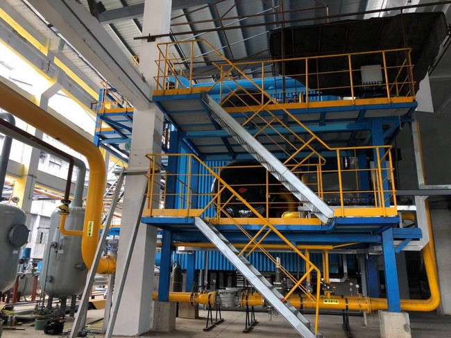
Wade Zhang

CEO of Taishan Group Taian Boao International Trade Co., Ltd. 30 years experience in Global industrial boiler market,  Over 300 boiler projects experience, including 21+ EPC projects. Projects span 30+ countries & regions, involving industries such as nuclear power, energy & electricity, municipal heating, mining, textiles, tires etc.

Key Factors Influencing Heat Transfer and Combustion Efficiency in Industrial Oil-Fired Boilers Read More »

How to Measure the Thermal Efficiency of an Industrial Biomass Boiler

How to Measure the Thermal Efficiency of an Industrial Biomass Boiler

Industrial biomass boilers are increasingly adopted for their renewable energy potential, carbon-neutral benefits, and cost-effectiveness. However, to ensure they deliver real value, operators must accurately measure thermal efficiency—the benchmark for how well the system converts the energy content of biomass fuel into useful heat or steam. Without proper measurement, facilities risk inefficient combustion, excessive fuel consumption, and higher operational costs.

The thermal efficiency of an industrial biomass boiler is calculated by comparing the useful heat output (usually in the form of steam or hot water) to the energy input from the biomass fuel. This is typically done using two accepted methods: the Direct Method (based on output-to-input ratio) and the Indirect Method (based on accounting for heat losses). Due to the variable nature of biomass (moisture content, ash, and calorific value), precise measurement depends on accurate fuel analysis, combustion monitoring, and flue gas evaluation.

Let’s explore how to properly measure and manage the efficiency of a biomass boiler system.

biomass power station

What Is Thermal Efficiency and Why Is It Important in Biomass Boilers?

Biomass boilers are widely chosen for their renewable fuel source and lower carbon footprint, but their real-world performance depends heavily on thermal efficiency—the percentage of fuel energy successfully converted into useful heat. Unlike fossil fuels, biomass comes in many forms with varied moisture, ash, and energy content. This makes it even more important to monitor and maximize how efficiently the boiler system extracts energy from the fuel. Low thermal efficiency doesn’t just mean more wood burned—it means higher costs, more emissions, and poorer environmental returns on your investment.

Thermal efficiency in biomass boilers refers to the ratio of useful heat output (in the form of steam or hot water) to the total energy content of the biomass fuel input. It measures how effectively the boiler converts the chemical energy in biomass into usable thermal energy. High thermal efficiency reduces biomass consumption, cuts operational costs, improves sustainability outcomes, and ensures compliance with energy and emissions standards.

In short, thermal efficiency is the performance heartbeat of every biomass boiler—whether in industry, district heating, or agriculture.

Thermal efficiency measures how much of the biomass fuel's energy is converted into usable heat in a boiler system.True

It is a critical indicator of biomass boiler performance, affecting fuel use, emissions, and overall operational costs.


🔍 How Thermal Efficiency Is Defined and Measured in Biomass Boilers

ConceptDescription
Fuel Input EnergyThe total calorific value (energy content) of biomass fuel used
Useful Output EnergyThe heat transferred to steam or hot water for end-use
Thermal Efficiency (%)Ratio of output energy to input energy, expressed as a percent

🛠 Thermal efficiency is typically calculated using either:

  • The Direct Method (based on fuel consumption and steam output), or

  • The Indirect Method (by subtracting all heat losses from 100%)


🌾 Why Thermal Efficiency Matters in Biomass Boiler Systems

Importance AreaExplanation
Fuel ConsumptionHigher efficiency = less biomass burned for the same output
Operating CostReduces delivery, storage, and handling costs
Emission ReductionLower fuel use means fewer particulates and CO₂ emitted
System LifespanEfficient combustion reduces fouling and corrosion
Sustainability ImpactValidates renewable energy targets and carbon reduction goals

Efficient boilers can cut biomass usage by 15–25%, depending on design and maintenance practices.


📊 Typical Efficiency Ranges for Biomass Boilers

Boiler TypeThermal Efficiency (%)Notes
Fixed Grate Boiler65–75Simple design, higher losses
Moving Grate/Stoker75–80Better fuel-air control
Fluidized Bed (FBC/CFB)80–88High combustion efficiency, multi-fuel capable
Gasification Boilers85–90High efficiency but higher CAPEX
Condensing Biomass Units90–92Recovers latent heat; best for low-temp systems

System design, fuel quality, and operation practices all influence where in this range a system performs.


🧪 Case Example: 10 TPH Wood Chip-Fired Biomass Boiler

ParameterValue
Fuel Input (Wood Chips)3,000 kg/hr (CV = 3,200 kcal/kg)
Steam Output10,000 kg/hr
Steam Enthalpy660 kcal/kg
Feedwater Temp85°C (Enthalpy ~85 kcal/kg)
Thermal Efficiency~81.5% (Direct Method)

→ Efficiency optimization strategies reduced fuel use by 18%, saving $39,000/year and avoiding 78 tons CO₂/year.


🛠 Key Factors Affecting Thermal Efficiency in Biomass Boilers

FactorImpact on EfficiencyOptimization Strategy
Fuel Moisture ContentHigh moisture lowers combustion temp and efficiencyUse drier fuel or install fuel dryers
Combustion Air ControlToo much or too little air reduces burn qualityInstall O₂ trim system and tune dampers
Heat Recovery SystemsUnused energy exits via flue gasesAdd economizer or air preheater
Boiler InsulationPoor insulation leads to radiation lossUpgrade refractory and pipe insulation
Ash Handling and FoulingAsh buildup reduces heat transferImplement soot blowers and regular cleaning
Boiler Load ControlLow part-load operation drops efficiencyMatch load using smart modulation systems

→ Addressing these variables can boost thermal efficiency by up to 10%.


📈 Biomass Boiler Efficiency Monitoring Tools

ToolPurpose
Fuel Flow MeterTracks biomass input in real time
Steam Flow and Pressure SensorMonitors thermal output
O₂/CO Flue Gas AnalyzerIndicates combustion efficiency
Stack Temperature SensorDetects energy losses in exhaust gas
Online Efficiency DashboardCombines all data to calculate and trend efficiency

Efficient systems rely on continuous data—not assumptions.


In conclusion, thermal efficiency is the defining metric of performance for biomass boiler systems. It governs how much fuel is needed, how cleanly it burns, and how much steam or heat is delivered. With increasing pressure to lower emissions and prove carbon neutrality, optimizing and maintaining high thermal efficiency is essential—not just for cost savings, but for the credibility and sustainability of the entire biomass energy strategy.

How Is the Direct Method Used to Measure Thermal Efficiency of a Biomass Boiler?

Biomass boilers come in many configurations—from fixed grates to circulating fluidized beds—and operate using fuels with varying moisture, calorific values, and ash content. This variability makes it essential to accurately measure thermal efficiency to ensure the system performs optimally. One of the most practical and widely accepted techniques is the Direct Method, especially during routine performance audits or operator checks. It focuses purely on real-world measurable values without requiring complex combustion analysis.

The Direct Method calculates the thermal efficiency of a biomass boiler by dividing the useful heat output (steam or hot water produced) by the energy input from the biomass fuel. It requires basic measurements like steam output rate, feedwater temperature, fuel consumption rate, and biomass calorific value. This method is fast, field-friendly, and ideal for routine efficiency assessments of biomass boiler systems.

While it doesn’t provide insights into why efficiency may be low, it effectively tells you how well your boiler is performing in real time.

The Direct Method measures biomass boiler thermal efficiency using actual steam output and fuel energy input.True

It is a practical way to assess boiler performance by comparing how much useful energy is produced versus how much fuel energy is consumed.


🔧 What Parameters Are Needed for the Direct Method?

ParameterPurposeMeasurement Method
Steam Output Rate (kg/hr)Measures useful heat deliveredSteam flow meter (vortex, DP, etc.)
Steam Pressure and TemperatureUsed to find steam enthalpy from steam tablesPressure/temperature transmitters
Feedwater Temperature (°C)Baseline energy level before steam is producedRTD or thermocouple sensor
Biomass Fuel Consumption Rate (kg/hr)Total fuel energy inputGravimetric or belt scale
Calorific Value of Biomass (kcal/kg or MJ/kg)Converts fuel quantity to energyBomb calorimeter test or supplier data

The accuracy of each parameter directly impacts the reliability of the final efficiency calculation.


📏 Direct Method Formula (Without Complex Math)

To avoid using complex equations your editor can’t recognize, here’s the conceptual format of the Direct Method in plain terms:

Thermal Efficiency (%) = (Heat output in steam) ÷ (Heat input from fuel) × 100

🛠 To find:

  • Heat output in steam: Multiply steam flow by the energy each kg of steam carries (steam enthalpy − feedwater enthalpy)

  • Heat input from fuel: Multiply fuel consumption by the calorific value of the biomass


📊 Example Calculation – 6 TPH Wood Chip-Fired Boiler

ParameterValue
Steam flow rate6,000 kg/hr
Steam pressure10 bar (saturated steam)
Steam enthalpy~665 kcal/kg
Feedwater temperature80°C (enthalpy ~85 kcal/kg)
Biomass fuel used (wood chips)2,500 kg/hr
Calorific value of wood chips3,100 kcal/kg

🧮

  • Heat output = (665 − 85) × 6,000 = 3,480,000 kcal/hr

  • Heat input = 2,500 × 3,100 = 7,750,000 kcal/hr

  • Efficiency = (3,480,000 ÷ 7,750,000) × 100 = 44.9%

📉 Note: The low efficiency suggests issues like high moisture content, excess air, or heat losses—not uncommon in under-optimized systems.


✅ Advantages of the Direct Method for Biomass Boilers

BenefitExplanation
SimplicityRequires only basic operational data
SpeedEfficiency can be calculated in minutes
Field-FriendlyDoesn’t need lab-based gas or ash analysis
VersatilityWorks for all boiler types: stoker, FBC, CFB
Ideal for Routine MonitoringEnables regular operator performance checks

It’s a powerful tool for daily, weekly, or post-maintenance evaluations.


⚠️ Limitations of the Direct Method

LimitationConsequence
No insight into loss causesDoesn’t show if loss is due to flue gas, moisture, etc.
Depends on measurement accuracyErrors in fuel flow or steam sensors skew results
Assumes steady-state operationTransient loads can misrepresent real performance

For in-depth diagnostics, use the Indirect Method in parallel with Direct Method data.


📈 Best Practices to Improve Accuracy of Direct Method

PracticeReason
Calibrate steam and fuel meters regularlyAvoids drift in readings
Test biomass calorific value periodicallyMoisture and source variation impact CV
Record at stable load periodsReduces variability in steam/fuel readings
Use real-time efficiency dashboardsEnables trend monitoring, alerts, and optimization

Modern biomass boiler control systems often integrate Direct Method analytics with SCADA or cloud platforms.


In conclusion, the Direct Method is a simple yet effective way to measure the thermal efficiency of biomass boilers, especially when real-time decision-making is required. It helps quantify boiler performance based on fuel consumed and steam produced—without needing complex heat loss analysis. While not diagnostic by itself, it serves as a first-line tool for efficiency monitoring, energy audits, and compliance validation in biomass-based heating and power systems.

How Does the Indirect Method Identify Key Heat Losses in Biomass Combustion?

Unlike the Direct Method, which simply compares energy input and output, the Indirect Method (or Heat Loss Method) offers a deeper dive. It doesn’t just tell you how efficient a biomass boiler is—it tells you why it’s not more efficient. This makes it an invaluable tool for diagnosing energy losses and improving combustion processes. Biomass combustion presents unique challenges, such as variable moisture, ash content, and volatile organic matter. The Indirect Method is especially suited to identifying and quantifying key loss pathways that sap thermal performance in such systems.

The Indirect Method identifies key heat losses in biomass combustion by analyzing flue gas composition, fuel properties, and operational parameters to calculate energy lost through dry flue gases, water vapor, unburned carbon, radiation, and convection. By subtracting these losses from 100%, it reveals actual boiler efficiency and pinpoints the sources of inefficiency, enabling targeted performance improvements.

It is widely used in detailed energy audits and performance tuning of biomass boilers across industries.

The Indirect Method identifies biomass boiler heat losses by calculating specific inefficiencies such as flue gas and moisture losses.True

It provides diagnostic insights into combustion inefficiency, helping engineers understand and reduce fuel waste.


🔧 Major Heat Losses Identified by the Indirect Method

Loss CategoryDescriptionTypical Share (%)
Dry Flue Gas LossHeat carried away by hot combustion gases5–12%
Evaporation of Moisture in FuelEnergy used to evaporate water in biomass3–10%
Hydrogen in Fuel (Latent Loss)Heat lost from forming water vapor during combustion4–8%
Radiation and Convection LossHeat escaping from boiler surface and piping1–2%
Unburnt Carbon in AshFuel particles not combusted, removed with ash1–6%
Incomplete Combustion (CO loss)Energy lost as CO instead of full CO₂ combustion0.5–3%

→ These losses vary based on biomass type, combustion quality, boiler design, and operating conditions.


🧾 Required Parameters for Indirect Method (Biomass Boiler)

ParameterMeasurement Tool or Source
Flue gas temperatureStack thermocouple
Ambient temperatureOnsite thermometer
O₂ concentration in flue gasZirconia analyzer or flue gas probe
CO / CO₂ levelsFlue gas analyzer
Fuel moisture content (%)Laboratory moisture analyzer or handheld probe
Fuel composition (C, H, N, S)Lab elemental analysis
Ash carbon contentProximate analysis of ash samples

These inputs are used in standard efficiency equations or spreadsheet-based calculation tools.


📊 Real-World Example – 10 TPH Biomass Boiler (Wood Chips)

Parameter / Loss CategoryValue
Flue gas temp220°C
O₂ in flue gas6.5%
Fuel moisture content35%
Unburned carbon in ash4.2%
CO in flue gas180 ppm
Dry flue gas loss7.8%
Moisture evaporation loss6.4%
H₂ combustion loss4.6%
Unburnt carbon loss3.1%
CO loss1.2%
Radiation & convection loss1.5%
Total losses24.6%
Efficiency (100 − losses)75.4%

→ Result: Efficiency improved to 82.2% after adjusting combustion air and improving ash burnout.


🔍 Interpretation of Each Heat Loss

1. Dry Flue Gas Loss

  • Cause: High excess air or high flue gas temp

  • Solution: Use O₂ trim control and economizer

2. Fuel Moisture Loss

  • Cause: High water content in biomass fuel

  • Solution: Pre-dry fuel or switch to lower-moisture feedstock

3. Hydrogen Combustion Loss

  • Cause: Natural hydrogen in biomass forms water vapor

  • Solution: Cannot be eliminated, but minimize excess air to reduce impact

4. Unburned Carbon in Ash

  • Cause: Poor combustion, low furnace temperature

  • Solution: Adjust grate speed, air distribution, or bed temperature

5. CO (Incomplete Combustion) Loss

  • Cause: Improper air-fuel ratio

  • Solution: Improve burner design or air staging

6. Radiation/Convection Loss

  • Cause: Heat radiated from boiler casing and piping

  • Solution: Upgrade insulation


📈 Comparative Heat Loss Breakdown by Fuel Type

Fuel TypeMoisture LossAsh LossCO LossTotal Loss Range (%)
Wood Chips (35% MC)HighMediumLow22–28
Bamboo ResidueMediumHighMedium25–30
Pellets (<10% MC)LowLowLow15–20
RDF / Waste BiomassMedium–HighHighHigh28–35

High-moisture and high-ash fuels require enhanced combustion control and post-combustion cleaning.


🛠 Benefits of Using the Indirect Method in Biomass Systems

BenefitExplanation
Pinpoints Loss SourcesHelps target upgrades where they matter most
Improves Combustion EfficiencyIdentifies air/fuel balance and burnout problems
Supports Maintenance PlanningReveals buildup or wear causing heat loss
Guides Fuel SelectionCompares performance across biomass feedstocks
Aligns with ISO 50001Supports energy management certification

Auditors and engineers use this method to validate performance guarantees and efficiency improvement ROI.


In conclusion, the Indirect Method is the most diagnostic and insightful tool for measuring thermal efficiency in biomass combustion. It reveals exactly where energy is lost—from flue gases and moisture to incomplete combustion and poor insulation. For biomass boilers that face wide fuel variability and complex combustion behavior, this method offers clarity, control, and a roadmap to optimization.

What Factors Unique to Biomass (e.g., Moisture Content, Ash) Affect Efficiency Readings?

Biomass is a highly diverse and renewable fuel source, but its variable nature presents unique challenges in boiler operation and efficiency measurement. Unlike standardized fossil fuels, biomass can range from dry wood pellets to high-moisture agri-residues or waste-derived fuels, each with different combustion behavior, ash characteristics, and energy content. These variations not only affect the actual performance of the boiler but also distort how thermal efficiency is calculated—especially when using standard methods like the Direct or Indirect Method.

Unique biomass characteristics such as moisture content, ash content, volatile matter, and fuel variability significantly affect efficiency readings by altering combustion temperature, increasing flue gas losses, causing unburnt residues, and complicating accurate calorific value assessments. These factors introduce both actual and apparent inefficiencies, which must be accounted for during efficiency evaluation to avoid underestimating or misinterpreting boiler performance.

Accurate efficiency interpretation in biomass systems must therefore be tailored to fuel properties—not just boiler design.

Biomass fuel properties like moisture and ash content affect boiler efficiency readings.True

These characteristics influence combustion quality, heat loss, and the accuracy of both Direct and Indirect Method efficiency calculations.


🌾 Key Biomass Fuel Characteristics That Affect Efficiency Readings

Biomass FactorEffect on Efficiency and MeasurementTypical Range in Biomass Fuels
Moisture Content (%)Reduces calorific value and increases heat loss via evaporation10–55%
Ash Content (%)Increases unburnt loss and fouling, affects PM removal systems0.5–15%
Volatile Matter (%)Alters combustion dynamics and flame stability60–85%
Fixed Carbon (%)Determines sustained heat release10–30%
Particle Size / Bulk DensityAffects combustion uniformity and feeding rateVaries widely
Inorganic Content (e.g., Cl, K, Na)Increases corrosion, slagging, and emission complexityVaries with waste biomass

These factors fluctuate not only between biomass types but even within the same supply batch, especially in agri-residues.


🔍 Moisture Content: The Primary Efficiency Modifier

Impact AreaEffect on Efficiency
Combustion TemperatureHigh moisture absorbs heat, lowering furnace temp
Flue Gas LossesMore latent heat lost as steam
Calorific Value (CV)Lower CV = more kg of biomass needed per unit output
Drying Energy RequirementBoiler must first evaporate internal water
Biomass TypeMoisture (%)Net CV (kcal/kg)Thermal Efficiency Range (%)
Wood Pellets8–12~4,200–4,50085–90
Fresh Wood Chips40–55~1,800–2,40060–75
Straw Bales15–25~3,200–3,60070–80
Sugarcane Bagasse45–55~1,600–2,20058–72

→ Efficiency readings drop not because of poor boiler design, but due to energy wasted evaporating water.

🛠 Solution: Pre-drying fuel or installing fuel drying systems.


🧪 Ash Content and Its Effect on Apparent Efficiency

ImpactExplanation
Unburnt Carbon LossesAsh may carry unburned carbon out of combustion zone
Fouling and Heat Transfer LossAsh deposits reduce heat exchange efficiency
Ash Disposal Energy CostHigh ash increases operational energy loss
Induced PM Removal LoadsESPs or baghouses work harder, adding pressure drops
Fuel TypeAsh Content (%)Common Impact
Wood Pellets<1.0Minimal impact
Bamboo / Palm Shells3–7Fouling and bag filter loading
Rice Husk15+Slagging, tube erosion
RDF (Waste)10–20High unburned loss + baghouse load

→ High ash fuels require advanced combustion and ash handling design to maintain efficiency.


📏 Volatile Matter and Combustion Behavior

| High Volatile Fuels | Burn quickly, release energy fast (may spike CO if not managed) |
| Low Volatile Fuels | Require longer residence time and hotter combustion zones |
| Impact on Efficiency Readings | Incomplete combustion = higher CO and unburnt losses (low Indirect efficiency) |

Efficiency will appear lower if burner setup doesn’t match volatile release timing.


📊 Example – Effect of Moisture and Ash on Efficiency Calculation

ScenarioWood Chips (40% MC, 2% Ash)Pellets (10% MC, 0.5% Ash)
Steam Output (kg/hr)10,00010,000
Fuel Input (kg/hr)3,4002,200
Fuel CV (kcal/kg)2,2004,400
Heat Input (kcal/hr)7.48 million9.68 million
Thermal Efficiency (Direct)73.2%91.0%

→ Same boiler, same steam output—but efficiency appears 18% lower due to fuel moisture.


🛠 Tips to Improve Efficiency Interpretation in Biomass Boilers

PracticeBenefit
Test CV of each fuel batchAvoid using assumed values; moisture skews CV
Dry fuel when possibleReduces latent heat loss from moisture evaporation
Analyze ash for unburnt carbonIdentifies real combustion inefficiency vs. apparent loss
Monitor CO and O₂ levelsIndicates if fuel is burning completely
Adjust air-fuel ratio by fuel typeImproves burn quality for volatile-rich fuels

Also consider using both Direct and Indirect Methods together for accurate insights.


In conclusion, biomass fuel properties—especially moisture and ash content—uniquely affect boiler efficiency readings. These fuels behave differently from fossil fuels and introduce additional complexity in combustion, heat transfer, and emissions. Understanding how these characteristics distort efficiency metrics is essential for accurate boiler evaluation, fuel management, and performance optimization. In the world of biomass combustion, efficiency is not just about numbers—it’s about understanding your fuel.

What Instruments and Data Are Required for Accurate Efficiency Measurement?

Thermal efficiency is the key metric that defines how effectively a boiler converts fuel into useful heat. Whether you use the Direct Method or the Indirect Method, your calculation is only as accurate as the data you feed into it. In biomass, gas, or coal-fired systems, conditions fluctuate—so relying on assumptions or outdated readings results in incorrect efficiency values, misguided maintenance, and avoidable fuel waste. To ensure trustworthy and actionable efficiency insights, a specific set of instruments and real-time data inputs is essential.

Accurate boiler efficiency measurement requires instruments that can precisely monitor steam output, fuel consumption, flue gas composition, combustion air parameters, and temperature points. Key devices include steam flow meters, fuel flow meters, flue gas analyzers (O₂, CO, CO₂), thermocouples for flue gas and feedwater temperature, and data acquisition systems. These sensors provide the real-time, high-resolution data needed to calculate both Direct and Indirect Method efficiencies with confidence.

Without these tools, efficiency numbers are unreliable—and so are any energy-saving decisions based on them.

Reliable efficiency measurement depends on accurate monitoring of fuel input, steam output, flue gas composition, and temperature.True

Each variable directly affects the heat input or output used to calculate thermal efficiency. Inaccurate instruments can result in misleading efficiency results.


🔍 Required Instruments for the Direct Method

InstrumentPurposeAccuracy Needed
Steam Flow MeterMeasures useful heat output in steam±1–2% (vortex or DP type)
Steam Pressure SensorHelps determine steam enthalpy±0.5% or better
Steam Temperature SensorNeeded for superheated steam calculations±1°C or better
Feedwater Temperature ProbeDetermines energy gain per kg of steam±0.5°C (RTD preferred)
Fuel Flow MeterMeasures biomass, oil, or gas input rate±1% (belt scale or Coriolis)
Fuel Calorific Value (CV)Converts mass or volume to energy content±1% (lab tested per batch)

→ These inputs feed into the thermal efficiency formula: useful energy out / fuel energy in × 100%.


🔬 Additional Instruments for the Indirect Method

InstrumentPurposeSensor Type/Notes
Flue Gas Temperature ProbeMeasures exhaust heat lossHigh-temp thermocouple
Ambient Air Temperature SensorNeeded to calculate net stack heat lossDigital RTD or thermocouple
Oxygen (O₂) AnalyzerDetermines excess air and combustion conditionZirconia probe or paramagnetic
CO / CO₂ Gas AnalyzerMeasures combustion completeness and CO lossInfrared gas sensor
Ash Sampling and AnalyzerMeasures unburnt carbon in ash for solid fuelsLab proximate analysis
Fuel Moisture AnalyzerDetermines evaporation loss in wet fuelsOven-dry or online NIR sensor
Air Flow Meter (optional)Assists in air-fuel tuning for NOₓ controlVane, ultrasonic, or pitot tube

→ These tools allow loss-specific calculations, such as flue gas, hydrogen, CO, and ash losses.


📊 Boiler Efficiency Instrumentation Matrix

InstrumentDirect MethodIndirect MethodRequired for Biomass Systems?
Steam Flow MeterOptional
Fuel Flow Meter
Calorific Value Tester✅ (high fuel variability)
Flue Gas Temp Sensor
Oxygen Analyzer (O₂)
CO/CO₂ Gas Analyzer
Feedwater Temp SensorOptional
Ambient Temp Sensor
Fuel Moisture Meter✅ (especially agri-residue)
Ash Analyzer✅ (for fixed bed systems)

🛠 Instrument Calibration and Integration

Best PracticeReason/Benefit
Calibrate flow meters quarterlyEnsures measurement accuracy over time
Install signal filtersReduces sensor noise in real-time data logging
Integrate into DCS/SCADAEnables live efficiency dashboards and alarms
Use DAHS (Data Acquisition System)Stores time-stamped records for audits
Synchronize sensor timestampsPrevents time mismatch in hourly performance reporting

Proper calibration and integration are as important as the sensors themselves.


🧪 Example – Real-Time Efficiency Monitoring in a 12 TPH Biomass Boiler

InstrumentValue
Steam Output12,000 kg/hr
Steam Enthalpy660 kcal/kg
Feedwater Enthalpy85 kcal/kg
Biomass Input3,300 kg/hr
Biomass CV2,900 kcal/kg
O₂ in Flue Gas5.4%
Flue Gas Temp230°C
CO in Flue Gas110 ppm

→ Calculated Efficiency:

  • Direct Method: ~79.6%

  • Indirect Method: ~78.1% (losses identified: 8.2% dry gas, 6.4% moisture, 2.1% unburned carbon)

→ Enabled fuel feed adjustment and air tuning for a 3.5% efficiency improvement.


📈 Benefits of a Fully Instrumented Efficiency Monitoring System

BenefitResult
Higher Operational EfficiencyContinuous tuning based on real conditions
Fuel SavingsDetects unnecessary fuel use or load mismatches
Better Emission ControlSupports cleaner combustion with fewer NOₓ and CO
Audit-Ready ReportingSupports compliance with ISO 50001 and regulators
Predictive MaintenanceEarly warning of burner, sensor, or tube fouling

Boiler plants that invest in full instrumentation typically see 3–10% efficiency improvement over time.


In conclusion, accurate efficiency measurement is only possible with a complete and calibrated set of instrumentation, covering steam production, fuel consumption, combustion quality, and flue gas analysis. Whether applying the Direct or Indirect Method, these tools turn raw operational data into insights that drive lower fuel costs, higher uptime, and regulatory compliance. For any serious boiler operator, measurement is the first step toward meaningful performance improvement.

How Can Regular Efficiency Tracking Help Optimize Fuel Use and Reduce Emissions?

Boiler systems are one of the most energy-intensive assets in any industrial facility. Yet many operations run their boilers on static settings without tracking how efficiently fuel is being converted into steam. This results in hidden fuel waste, increased emissions, and missed opportunities for savings. Regular efficiency tracking is the game-changer—it transforms boilers from “set-and-forget” machines into dynamic systems of continuous improvement. Whether for biomass, gas, or coal-fired boilers, consistent performance monitoring helps uncover losses, guide maintenance, and verify real-world emission reductions.

Regular efficiency tracking optimizes fuel use and reduces emissions by continuously measuring boiler performance, identifying inefficiencies such as poor combustion or heat losses, and enabling timely adjustments. This leads to improved fuel-to-steam ratios, reduced CO₂, NOₓ, and SOₓ emissions, and better alignment with energy-saving and climate targets. Efficiency tracking also supports predictive maintenance and operational accountability, making it a core strategy for decarbonization and cost control.

If you can measure it, you can manage it—and in boiler operations, that means lower fuel bills and fewer emissions.

Regular efficiency tracking helps optimize boiler fuel use and reduce harmful emissions.True

Continuous monitoring allows real-time detection of performance issues and enables immediate corrective action, reducing waste and pollution.


📈 How Regular Tracking Drives Fuel Optimization

Efficiency InsightHow It Affects Fuel Use
Steam-to-Fuel RatioHelps detect fuel overuse or steam underproduction
Flue Gas TemperatureHigh stack temps = wasted heat → optimize recovery
Excess Air / O₂ ReadingsToo much air = energy loss in exhaust
Fuel CV TrackingMatches real fuel energy value to combustion control
Load vs. Efficiency CurveReveals best efficiency operating points

Plants that monitor these metrics regularly achieve 5–15% lower fuel consumption over time.


🔍 Emission Reduction Through Efficiency Monitoring

Parameter TrackedImpact on Emissions
CO / CO₂ Levels in Flue GasIndicates combustion quality, avoids CO spikes
NOₓ Trends vs. O₂Helps fine-tune air-fuel ratio for low-NOx burn
SO₂ vs. Fuel SulfurTracks effectiveness of desulfurization units
PM Levels with Fuel/Air LoadHelps adjust filters and reduce visible emissions

Each 1% increase in efficiency cuts CO₂ emissions by ~2.5% for fossil fuels.


🧪 Case Study: Efficiency Monitoring in a 12 TPH Biomass Boiler

Initial PerformanceAfter 3 Months of Tracking
Efficiency74.8%
Biomass Fuel Use (kg/hr)3,200
CO in Flue Gas180 ppm
CO₂ Emissions (tons/month)220

Savings:

  • Fuel cost reduction: $18,500/month

  • CO₂ reduction: ~35 tons/month

  • Payback on sensors and dashboard: <5 months


📊 Efficiency Tracking Dashboard Metrics (Live Example)

MetricTarget RangeCurrent ValueStatus
Thermal Efficiency (%)≥85%83.2%⚠ Monitoring
Flue Gas Temp (°C)<180198❌ Too High
O₂ (%)3–4%6.8❌ Excess Air
CO (ppm)<100120⚠ Needs Tuning
Steam/Fuel Ratio≥3.2 kg steam/kg fuel2.8❌ Inefficient

→ Based on these alerts, the operator retunes the air control and burner—resulting in immediate performance gain.


🛠 Tools for Implementing Regular Efficiency Tracking

ToolRole and Benefit
Steam & Fuel Flow MetersProvide live input/output ratio
Flue Gas AnalyzerDetects combustion quality and excess air
O₂ + CO SensorsIdentify burner inefficiency or load mismatch
Temperature Probes (Stack, Feedwater)Enable energy balance calculations
Online Efficiency DashboardTracks performance trends and provides alerts
CEMS (for emissions-linked sites)Validates real-time pollutant reductions

Modern plants use cloud dashboards with weekly and monthly analytics for performance reviews.


🔧 Efficiency Tracking Enables Operational Optimization

Action Triggered by MonitoringResult
Combustion tuning (O₂ high)Lower excess air → higher flame temp → lower fuel use
Soot blowing when temp risesClears ash fouling → restores heat transfer
Fuel feeder calibrationPrevents overfeeding → saves fuel
Air preheater tuningRecovers stack heat → increases efficiency
Filter/ESP maintenanceImproves PM capture → reduces pressure loss

Over time, these small adjustments add up to massive savings.


In conclusion, regular efficiency tracking transforms boiler performance from reactive to optimized. By identifying fuel waste, preventing emission spikes, and informing smarter operations, it becomes a powerful lever for both economic and environmental goals. In a decarbonizing world where energy costs and regulations are rising, those who monitor efficiency consistently will lead in cost control, compliance, and sustainability.

🔍 Conclusion

Measuring the thermal efficiency of an industrial biomass boiler is essential for maximizing its environmental and economic performance. By applying the Direct or Indirect Method and factoring in fuel quality, combustion characteristics, and system losses, operators can gain a clear understanding of how efficiently their biomass boiler performs. Regular efficiency assessments support fuel savings, better system maintenance, and long-term operational success.


📞 Contact Us

💡 Need assistance evaluating or improving the efficiency of your biomass boiler? Our team provides fuel analysis, combustion tuning, and energy optimization services for biomass systems across all industries.

🔹 Reach out today and unlock the full efficiency potential of your biomass boiler system! 🌿🔥📊

FAQ

What is thermal efficiency in an industrial biomass boiler?

Thermal efficiency refers to how effectively the energy from biomass fuel is converted into useful heat (typically steam or hot water). High thermal efficiency means better fuel utilization and lower operating costs.

What are the two standard methods to measure biomass boiler efficiency?

  1. Direct Method (Input-Output)

  2. Indirect Method (Heat Loss Analysis)
    These are globally recognized methods used to evaluate boiler performance and efficiency.

How does the Direct Method work for a biomass boiler?

The Direct Method calculates boiler efficiency as:

Efficiency (%) = (Steam Output × Enthalpy Gain) / (Fuel Input × Calorific Value) × 100
It’s simple and provides a quick efficiency snapshot, but doesn’t identify energy loss sources.

What does the Indirect Method involve?

The Indirect Method measures and sums all heat losses—such as flue gas loss, moisture loss, unburned fuel, and radiation—and subtracts the total from 100%.

Efficiency (%) = 100 – (Sum of Heat Losses)
This method is more comprehensive and diagnostic, helping improve combustion and fuel efficiency.

What specific factors affect thermal efficiency in biomass boilers?

Efficiency is influenced by moisture content, ash content, volatile matter, and fuel consistency. Wet or inconsistent biomass reduces combustion quality, increases flue gas loss, and lowers efficiency. Proper fuel prep and combustion control are key.

References

  1. Boiler Efficiency Methods Explainedhttps://www.energy.gov

  2. Direct and Indirect Boiler Efficiency Testinghttps://www.sciencedirect.com

  3. Biomass Fuel and Boiler Performancehttps://www.researchgate.net

  4. Combustion Efficiency in Biomass Systemshttps://www.bioenergyconsult.com

  5. Energy Loss Analysis in Industrial Boilershttps://www.epa.gov

  6. Fuel Moisture and Boiler Efficiency Correlationhttps://www.mdpi.com

  7. Biomass Combustion Technologieshttps://www.iea.org

  8. Steam Output and Boiler Performance Toolshttps://www.automation.com

  9. Industrial Biomass Boiler Optimization Guidehttps://www.energysavingtrust.org.uk

  10. Thermal Efficiency Standards for Biomass Boilershttps://www.asme.org
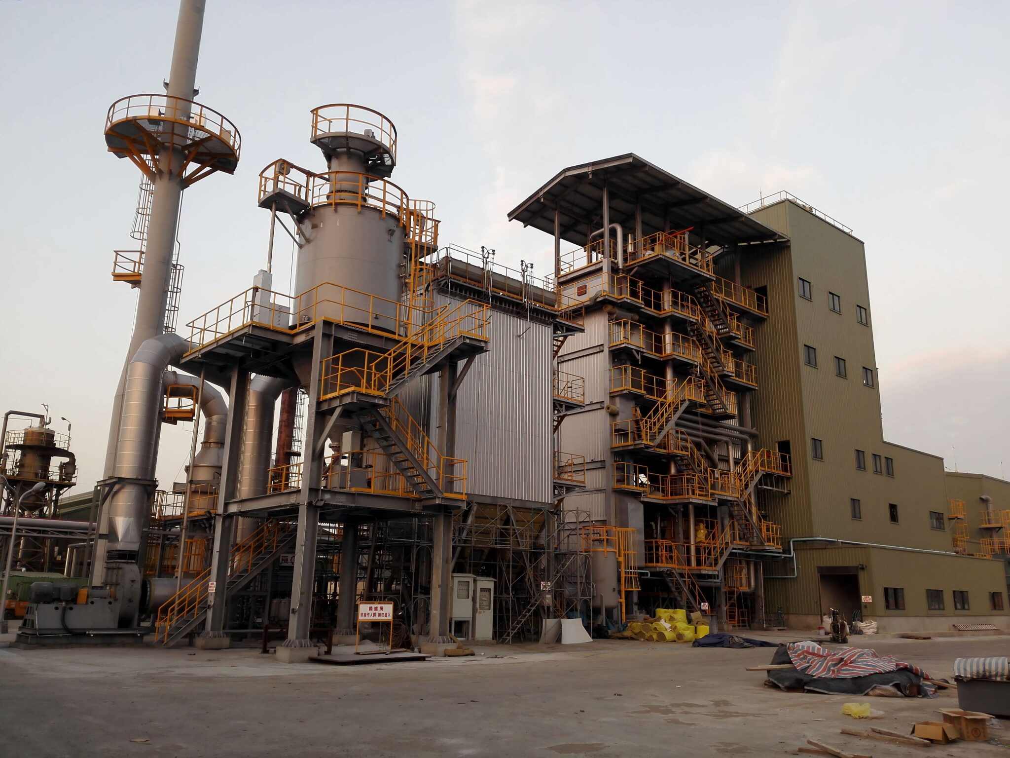
Wade Zhang

CEO of Taishan Group Taian Boao International Trade Co., Ltd. 30 years experience in Global industrial boiler market,  Over 300 boiler projects experience, including 21+ EPC projects. Projects span 30+ countries & regions, involving industries such as nuclear power, energy & electricity, municipal heating, mining, textiles, tires etc.

How to Measure the Thermal Efficiency of an Industrial Biomass Boiler Read More »

Scroll to Top

Get Quick Support

Taishan Group
Make an appointment with us to meet at exhibition
Quick Contact