How to Optimize Circulating Fluidized Bed Boiler Performance for Lower Operating Costs

How to Optimize Circulating Fluidized Bed Boiler Performance for Lower Operating Costs
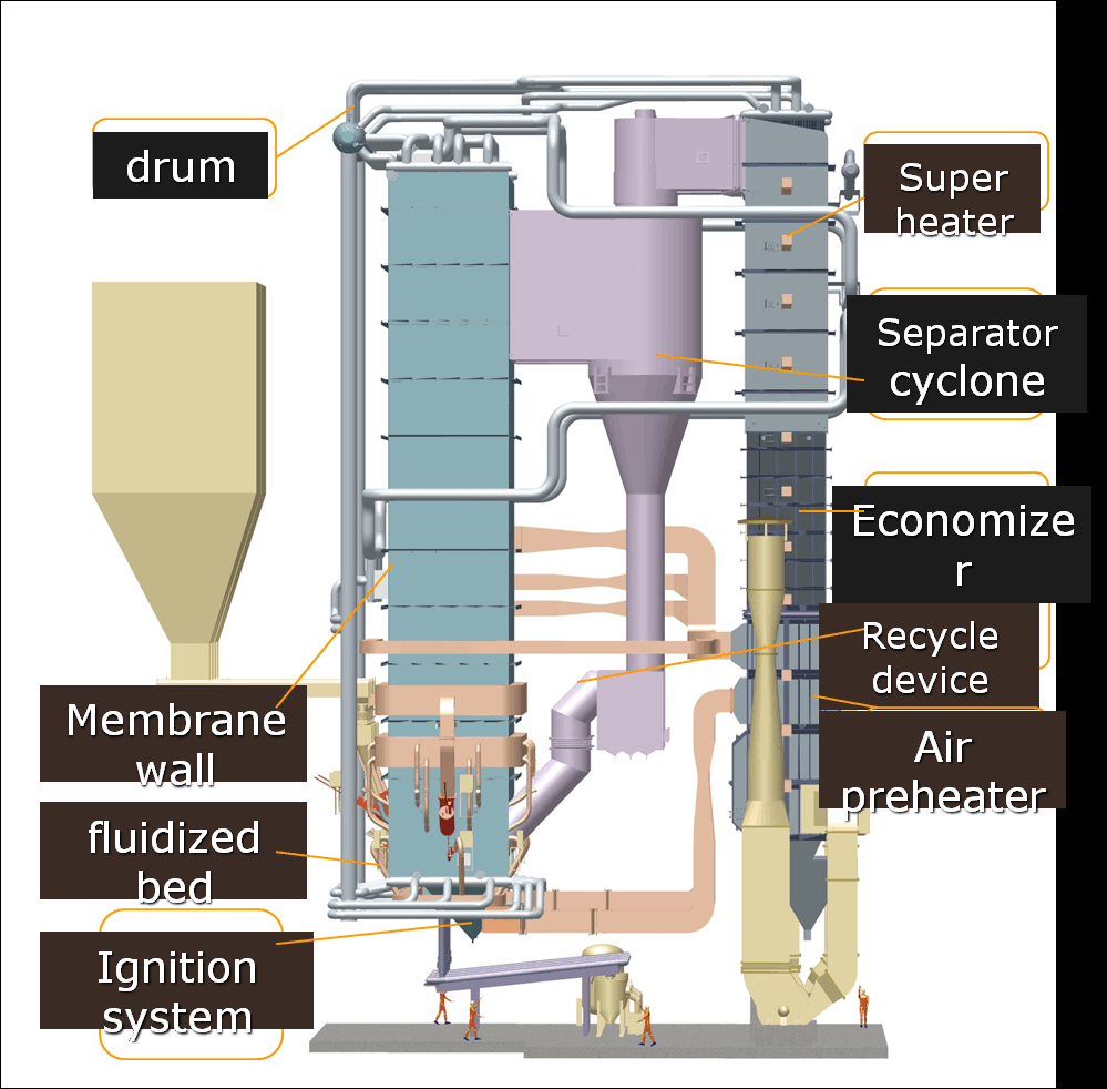
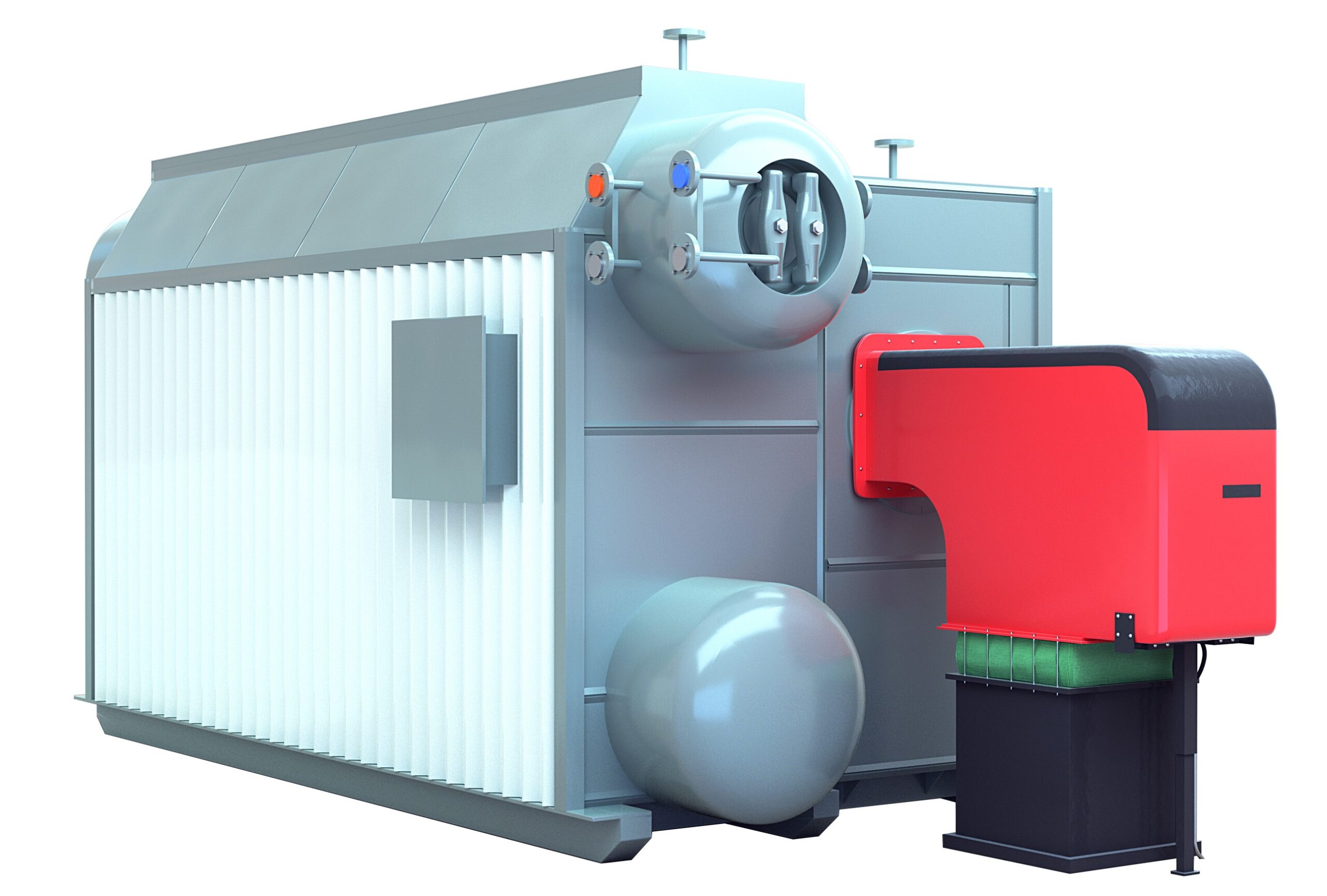
Circulating Fluidized Bed (CFB) boilers are favored in industrial and utility applications for their fuel flexibility, low emissions, and high combustion efficiency. However, without proper operational control and system optimization, these advantages can be undercut by excessive fuel use, ash handling issues, heat losses, and maintenance-related downtime—all of which raise operating costs. Efficient CFB boiler management is key to maximizing output while minimizing energy and maintenance expenses.
To optimize CFB boiler performance for lower operating costs, focus on critical areas such as fuel sizing and quality control, bed temperature management, air distribution tuning, ash handling optimization, and flue gas heat recovery. Additional efficiency gains can be achieved by implementing predictive maintenance, real-time monitoring, and combustion tuning strategies. Ensuring a stable fluidization regime and minimizing erosion or fouling in heat exchangers will also significantly reduce lifecycle costs.
Here’s a targeted guide to enhancing your CFB system’s cost-effectiveness and performance.
How Does Fuel Size, Moisture Content, and Calorific Value Impact CFB Combustion Efficiency?
Circulating Fluidized Bed (CFB) combustion is renowned for its fuel flexibility and low emissions. However, the efficiency of CFB systems heavily depends on the physical and chemical properties of the fuel—particularly particle size, moisture content, and calorific value. Poorly matched fuel can reduce combustion temperature, disrupt fluidization, and lead to incomplete burnout or increased ash handling costs. Understanding and optimizing these parameters is critical to maintaining stable, efficient combustion in CFB systems, especially when using diverse biomass, coal, or waste-derived fuels.
Fuel size, moisture content, and calorific value directly impact CFB combustion efficiency by influencing fluidization behavior, combustion temperature, and residence time. Fine and uniform particle size enhances burnout but may increase elutriation, while large particles reduce surface area and slow combustion. High moisture content lowers flame temperature and increases energy used for drying, reducing net efficiency. Calorific value determines how much useful energy is released; lower-grade fuels require more handling and produce more ash. Optimizing these fuel properties ensures complete combustion, minimizes heat losses, and maintains stable bed operation in CFB boilers.
In flexible-fuel CFB systems, fuel preparation and selection are as important as equipment design for sustained performance and emissions control.
Fuel particle size affects fluidization quality and combustion completeness in CFB systems.True
Smaller particles combust more completely but must be balanced to avoid entrainment; optimal sizing ensures stable bed dynamics and efficient burnout.
🔬 Fuel Particle Size and CFB Combustion
Particle size affects how fuel behaves in the fluidized bed:
| Size Range (mm) | Combustion Impact | Efficiency Consideration |
|---|---|---|
| <1 mm (fine) | Rapid burnout but risk of entrainment | May increase cyclone load, fly ash loss |
| 1–6 mm (optimal) | Good fluidization and complete combustion | Balanced burnout and minimal losses |
| >10 mm (coarse) | Poor surface area, slow ignition | Leads to unburned carbon and ash |
Ideal CFB Fuel Size Distribution:
| Fuel Type | Target Particle Size (mm) | Notes |
|---|---|---|
| Pulverized coal | 0.5–3 mm | Uniform sizing for optimal burnout |
| Biomass chips | 3–10 mm | Pre-shredded to minimize bridging |
| RDF pellets | <15 mm | Must be screened to remove oversize |
Oversized fuel particles increase combustion efficiency by extending burn duration.False
Oversized particles combust slowly and may not burn completely within the residence time, lowering efficiency and increasing unburned carbon.
💧 Moisture Content: The Hidden Efficiency Killer
High moisture content reduces combustion efficiency by absorbing energy for evaporation before ignition.
| Moisture Content (%) | Effect on Combustion | Efficiency Loss (%) |
|---|---|---|
| 5–15 | Ideal range for most fuels | Baseline |
| 20–30 | Longer ignition time, lower flame temp | 5–10% |
| >40 | Flame instability, risk of bed collapse | 10–20% |
For every 10% increase in moisture, the net calorific value drops by ~5–6%, requiring more fuel to maintain output. High moisture can also increase sorbent consumption and corrosion risk due to lower combustion temperatures.
🔥 Calorific Value and Fuel Energy Density
Calorific value (CV) determines how much usable energy the fuel contains.
| Fuel Type | Calorific Value (MJ/kg) | Ash Content (%) | CFB Efficiency Impact |
|---|---|---|---|
| Bituminous Coal | 24–30 | 10–15 | High CV supports stable bed temp |
| Wood Chips (dry) | 16–19 | 1–3 | Medium efficiency with good prep |
| Biomass (wet) | 8–14 | 1–7 | Lower bed temp, higher consumption |
| RDF/Sludge | 10–18 | 15–25 | High ash, requires combustion tuning |
Higher CV fuels provide more thermal energy per unit mass, improving combustion temperatures and supporting better sorbent reactivity for SO₂/NOx control. However, high-CV fuels must be balanced with CFB material flow to avoid excessive temperatures.
Low-calorific fuels require higher mass flow to maintain boiler load, increasing ash production and fuel costs.True
More fuel must be burned to deliver the same energy output, increasing handling requirements and reducing thermal efficiency.
📊 Combined Fuel Property Impact on CFB Efficiency
| Property | Ideal Range | Efficiency Influence |
|---|---|---|
| Particle Size | 1–6 mm | Enables complete combustion and good fluidization |
| Moisture Content | 10–20% | Minimizes drying losses and maintains flame temperature |
| Calorific Value | 18–25 MJ/kg | Provides stable bed operation and heat recovery potential |
Combining high moisture with large particle size and low CV is particularly harmful—leading to incomplete combustion, high unburned carbon, and excessive fuel feeding rates.
🧪 Case Study: Biomass CFB Retrofit
A CFB boiler at a pulp and paper mill was converted from coal to biomass. Initial efficiency dropped by 12%.
Challenges Identified:
Fuel size: 20–50 mm, irregular chips
Moisture: ~45% (green wood)
CV: ~12 MJ/kg
Corrective Measures:
Installed shredder to reduce fuel size to <10 mm
Added belt dryer to reduce moisture to 15%
Blended with RDF to raise average CV
Results:
Combustion efficiency improved by 14.6%
Bed temperature stabilized at 850–870°C
Unburned carbon reduced by 65%
Fuel feed rate decreased by 21%
Combustion temperature in CFBs can be stabilized by managing fuel properties like size and moisture.True
Proper fuel preparation ensures predictable burn rates and thermal profiles in the fluidized bed, maintaining efficiency.
🔧 Optimization Strategies for CFB Fuel Management
| Strategy | Target Parameter | Benefit |
|---|---|---|
| Pre-Screening and Shredding | Particle size uniformity | Enhances bed fluidity, avoids hot spots |
| Fuel Drying Systems | Moisture control | Improves net calorific value, reduces corrosion |
| Calorific Value Blending | Energy density | Stabilizes bed temperature and output |
| Ash Removal Scheduling | Unburned carbon control | Maintains heat exchange and air distribution |
| Bed Temperature Monitoring | Real-time combustion | Guides air/fuel ratio and load adjustments |
CFB plants with advanced fuel preparation lines often experience 3–5% higher efficiency and 30–50% less fouling and slagging.
Summary
In CFB combustion, fuel properties are not just inputs—they are performance drivers. Particle size, moisture content, and calorific value shape how fuel burns, how heat transfers, and how emissions form. Optimizing these characteristics through preparation, drying, and blending is essential for maintaining high combustion efficiency, bed stability, and fuel economy. In a CFB boiler, the key to sustained performance lies in controlling not just the fire—but the fuel feeding it.
Why Is Bed Temperature Control Crucial for Stable Combustion and Fuel Flexibility?
Circulating Fluidized Bed (CFB) combustion systems are designed for high-efficiency, low-emission performance with the ability to handle a wide range of fuels. But their fuel flexibility and combustion stability are only achievable with precise bed temperature control. If the bed gets too cold, combustion becomes unstable and incomplete. If it gets too hot, agglomeration, slagging, and emission spikes may occur. Bed temperature is the anchor point of the entire combustion process—affecting flame stability, sorbent reactivity, fuel burnout, and ash behavior. Managing it accurately is essential for reliable and efficient operation.
Bed temperature control is crucial in CFB combustion because it ensures stable combustion conditions, enables the efficient burning of diverse fuels, and protects system integrity. The optimal bed temperature (typically 800–900°C) allows complete fuel burnout, effective SO₂ and NOₓ reduction, and avoids agglomeration or defluidization. Deviations from this range can lead to flame instability, increased emissions, incomplete combustion, and operational failures. Temperature control enables fuel flexibility by allowing different fuels to burn under uniform thermal conditions.
In fluidized bed systems, the temperature of the bed is the temperature of success.
Bed temperature control in CFB boilers is essential for achieving complete combustion and stable operation.True
Stable temperatures maintain proper reaction kinetics, sorbent effectiveness, and fluidization characteristics.
🌡️ What Is Bed Temperature in a CFB Boiler?
In a CFB, the bed is a mixture of fuel particles, ash, and inert materials (like sand or limestone) suspended by high-velocity air. Combustion occurs within this fluidized bed, where:
Heat is transferred rapidly
Combustion reactions take place over extended residence time
Sorbents (like limestone) react with acid gases
The bed temperature must be maintained uniformly across the furnace volume—typically between 820°C and 870°C depending on fuel and design.
| Temperature Range (°C) | Combustion Effect | Operational Impact |
|---|---|---|
| <750 | Incomplete combustion, CO spike | Flame instability, unburned carbon |
| 800–850 | Ideal for most fuels | Stable combustion, efficient sorbent use |
| 900–950 | Agglomeration risk | Bed sintering, fluidization collapse |
| >1,000 | Slagging, tube overheating | Equipment damage, shutdown risk |
Bed temperatures above 950°C are beneficial for all fuels in CFB systems.False
Excessive temperatures can cause bed material to sinter, leading to defluidization and severe operational issues.
🔄 Why Temperature Affects Combustion Stability
| Parameter Influenced | Bed Temperature Role |
|---|---|
| Fuel Burnout | Sufficient temperature ensures complete combustion over extended residence time. |
| SO₂ Removal Efficiency | Limestone sorbents react best between 820–880°C. |
| NOₓ Formation Control | Uniform lower temperatures limit thermal NOₓ formation. |
| Fluidization Dynamics | Stable temperature prevents sticky particles and bed collapse. |
| Emission Compliance | Controls CO, NOₓ, and unburned hydrocarbons. |
If temperature fluctuates, combustion reactions slow, and unburned carbon increases, which reduces boiler efficiency and raises emissions.
📉 Impact of Poor Bed Temperature Control
| Symptom | Cause | Efficiency Consequence |
|---|---|---|
| Incomplete combustion | Bed too cold | Fuel waste, high CO emissions |
| Agglomeration in bed | Bed too hot | Shutdown for cleaning |
| Increased limestone use | Sub-optimal SO₂ capture | Higher O&M costs |
| Fly ash carryover | Poor particle conversion | Higher particulate emissions |
| Load swings and flameout | Rapid temp changes | Boiler instability |
In one biomass-fueled CFB plant, poor temperature control caused flame instability during load ramping, forcing operators to reduce turndown capacity by 25%.
🔧 Methods for Controlling Bed Temperature
| Method | Description | Effectiveness |
|---|---|---|
| Fuel Feed Rate Adjustment | More fuel raises temperature, less lowers it | Primary control method |
| Secondary Air Injection | Enhances mixing, improves combustion stability | Supports temperature homogenization |
| Recycled Flue Gas Control | Dilutes oxygen and temp to manage heat release | Helps with high-CV fuels |
| In-Bed Heat Exchangers | Extracts heat to prevent over-temperature zones | Especially useful in waste-burning CFBs |
| Automated PID Control Loops | Uses real-time data to modulate operations | Maintains stable thermal profile |
CFB systems rely solely on manual fuel adjustments to control bed temperature.False
Modern CFBs use automated systems that integrate feedback from temperature sensors, fuel flow, and air distribution to optimize temperature control.
📊 Case Study: Multi-Fuel CFB Optimization
A 100 MW CFB unit in a pulp and paper plant burns wood chips, sludge, and coal.
Initial Issues:
Bed temps fluctuating 790–930°C
Poor burnout of wet sludge
High limestone usage
Actions Taken:
Installed bed thermocouples at multiple zones
Implemented fuel-specific feed modulation logic
Upgraded PID controller for tighter temperature feedback
Results:
Bed temp stabilized at 840 ±15°C
Fuel flexibility improved (30% sludge share)
Limestone consumption dropped by 18%
Overall efficiency rose by 6.3%
Bed temperature control is a key enabler of fuel flexibility in CFB boilers.True
Different fuels require different combustion conditions; maintaining stable temperature ensures all fuels can burn efficiently.
📋 Monitoring and Instrumentation for Temperature Control
| Tool | Role |
|---|---|
| In-bed Thermocouples | Measure real-time temperature at various depths |
| Infrared Cameras | Detect hot spots across bed surface |
| Fuel Moisture Sensors | Predict fuel heating value and drying needs |
| Air Flow Meters | Control primary/secondary air delivery |
| Combustion Control PLC/SCADA | Integrates all sensors to optimize setpoint control |
Advanced CFB systems use digital twins to simulate temperature responses to changing fuels, allowing predictive temperature adjustments before efficiency loss occurs.
Summary
In CFB combustion systems, bed temperature is the foundation of efficiency, stability, and fuel adaptability. It governs everything from fuel burnout and emissions to heat recovery and equipment longevity. Proper control allows diverse fuels—including low-grade biomass, sludge, and refuse—to combust completely and cleanly. Without stable bed temperatures, even high-quality fuel won’t burn effectively. By integrating advanced sensors, fuel modulation, and automated feedback control, operators can keep CFB boilers running at peak efficiency—even under variable load and mixed-fuel conditions. In fluidized bed technology, temperature control isn’t just a parameter—it’s the performance gatekeeper.
How Can Optimal Air Distribution Reduce Excess Air Losses and Improve Combustion?
In combustion systems, air is as important as fuel—but more isn’t always better. Supplying too much air beyond the stoichiometric requirement results in excess air, which carries heat away with the flue gases and lowers system efficiency. Poor air distribution—such as uneven primary, secondary, or tertiary air—can also cause incomplete combustion, flame instability, and increased pollutant formation. Conversely, optimal air distribution ensures efficient fuel burnout, maximizes thermal output, and reduces losses associated with excess air. Mastering airflow control is key to unlocking high-efficiency, low-emission combustion.
Optimal air distribution reduces excess air losses and improves combustion by delivering the right amount of air, in the right place, at the right time. Properly balanced primary, secondary, and tertiary air ensures complete mixing with fuel, stabilizes the flame, and prevents hot and cold zones within the combustion chamber. This minimizes the need for excess air, thereby reducing stack losses, improving thermal efficiency, and lowering emissions such as CO and NOₓ. Real-time airflow control, burner geometry, and feedback systems enable precise distribution to match load and fuel conditions.
Air is free—but moving too much of it through a combustion system comes at a significant energy cost.
Optimal air distribution in combustion systems reduces the need for excess air and improves efficiency.True
Even air delivery ensures complete combustion with minimal heat loss through the stack, maximizing usable energy from the fuel.
🔬 Understanding Air Distribution in Combustion
| Air Type | Function | Typical Air Ratio (of total air) |
|---|---|---|
| Primary Air | Transports and mixes with fuel initially | 20–40% |
| Secondary Air | Supports complete combustion, stabilizes flame | 30–60% |
| Tertiary Air | Finishes burnout, reduces NOₓ | 0–20% |
| Excess Air | Extra oxygen to ensure complete burn | Typically 10–25% above stoichiometric |
Each air stream serves a role in the combustion sequence. If misaligned—either over- or under-supplied—it leads to flame instability, incomplete combustion, or unnecessary heat loss.
📉 How Excess Air Reduces Efficiency
Excess air lowers combustion temperature and increases stack losses:
| Excess Air (%) | Flue Gas O₂ (%) | Efficiency Loss (%) | Comment |
|---|---|---|---|
| 10 | ~2 | Minimal | Ideal zone |
| 25 | ~4 | 2–3% loss | Acceptable in many systems |
| 50 | ~8 | 5–7% loss | Efficiency starts to drop |
| 100 | ~11 | 10–12% loss | Severe loss and flame cooling |
Excess air requires heating more nitrogen and oxygen, which leaves the stack as wasted energy. In gas-fired systems, every 1% O₂ above optimal can reduce efficiency by ~0.5–1%.
Excess air improves fuel efficiency in industrial combustion systems.False
Excess air reduces flame temperature and increases heat loss through flue gases, decreasing overall system efficiency.
🔧 Benefits of Optimal Air Distribution
| Benefit | Description |
|---|---|
| Improved Flame Stability | Consistent ignition and complete fuel burnout |
| Reduced CO/NOₓ Emissions | Uniform temperature reduces thermal NOₓ and CO |
| Lower Stack Temperature | More heat is absorbed into the system |
| Higher Combustion Efficiency | Less air heated unnecessarily |
| Better Heat Transfer | Even flame front improves exchanger performance |
In solid-fuel boilers, poor air staging often leads to carbon carryover or unburned fuel in ash. Optimized air zones improve carbon burnout and reduce ash disposal costs.
🧪 Case Study: Refinery Furnace Retrofit
A petroleum refinery faced high stack temperatures and CO emissions due to excess air averaging 60%.
Upgrades:
Added damper controls for primary/secondary air
Installed flue gas oxygen analyzers
Rebalanced burner air registers
Results:
Reduced excess air from 60% to 18%
CO emissions dropped by 65%
Stack temperature reduced by 40°C
Efficiency improved by 7.2%
Fuel savings: $130,000 annually
Better burner air staging improves emissions and fuel economy.True
Air staging enhances combustion completeness and reduces thermal NOₓ and unburned carbon.
📋 Key Tools for Air Distribution Optimization
| Tool/Technology | Function |
|---|---|
| Oxygen Trim Systems | Adjusts air delivery based on flue gas O₂ |
| VFD-Controlled Fans | Matches air flow to burner demand |
| Damper Control Systems | Balances flow between air zones |
| CFD Burner Modeling | Optimizes burner and air nozzle geometry |
| Air-Fuel Ratio Sensors | Measures mix accuracy in real-time |
With these tools, facilities can minimize excess air while avoiding flameout risks, even during load fluctuations.
📊 Practical Air Distribution Configurations
| Combustion System Type | Typical Air Distribution (%) | Optimization Notes |
|---|---|---|
| Natural Gas Burner | Primary: 30, Secondary: 70 | Minimize excess air to 10–15% |
| Pulverized Coal Boiler | Primary: 25, Secondary: 60, Tertiary: 15 | Use dynamic O₂ controls |
| Biomass CFB | Primary: 35, Secondary: 65 | Ensure deep fuel penetration and even burn |
| Rotary Kiln Burner | Primary: 20, Secondary: 50, Tertiary: 30 | Staging critical for NOₓ reduction |
Each fuel and system demands a unique air profile for optimal efficiency. Adjusting air staging per fuel type ensures clean, complete combustion.
🧠 Advanced Approaches: AI and Adaptive Control
| Technology | Role | Benefit |
|---|---|---|
| AI Combustion Optimization | Learns from data to tune air-fuel ratio | Maintains ideal O₂ and excess air levels |
| Digital Twins | Simulates airflow impact on combustion | Helps design better air staging strategies |
| Real-Time Thermal Imaging | Detects flame and bed temp distribution | Identifies air imbalance or fuel maldistribution |
Facilities using AI-based airflow tuning have reported 2–4% gains in efficiency and 30–50% emission reductions under dynamic loads.
Summary
Optimal air distribution is not just about how much air you supply—it’s about how you deliver it. Poor distribution leads to excess air, heat loss, and unstable combustion. Precise control of primary, secondary, and tertiary air flows ensures that fuel and oxygen meet at the right time and place for efficient, complete combustion. With the right monitoring tools and control systems, plants can significantly reduce fuel use, emissions, and maintenance. In combustion engineering, balanced air equals balanced performance—and a balanced budget.

What Role Does Ash Management and Bottom Bed Material Control Play in Reducing Costs?
In Circulating Fluidized Bed (CFB) boilers and other solid-fuel combustion systems, ash is an inevitable byproduct. But how it’s managed—and how the bottom bed material is maintained—has a major impact on operational efficiency, fuel consumption, maintenance costs, and environmental compliance. Improper ash handling leads to buildup, wear, clogging, and unplanned shutdowns. Uncontrolled bed material behavior disrupts combustion and fluidization, requiring more fuel and more maintenance. On the flip side, effective ash management and bed material control lower operating costs and improve combustion stability.
Ash management and bottom bed material control reduce costs by maintaining optimal fluidization, preventing system wear, minimizing unburned carbon losses, and reducing the need for frequent material replenishment. Proper ash extraction ensures continuous operation without slagging or ash buildup, while maintaining the right bed particle size and composition enhances combustion efficiency, stabilizes bed temperature, and prevents damage to cyclones, ash coolers, and feed systems. These practices reduce fuel use, downtime, and disposal expenses, directly translating into lower operating costs and higher reliability.
Efficient combustion doesn’t end with ignition—it continues through the careful management of what remains.
Effective ash and bed material control in CFB systems helps reduce maintenance and operating costs.True
By preventing clogs, slagging, and abrasion, these controls extend component life and reduce the need for shutdowns and cleaning.
🧱 Types of Ash in CFB and Their Impact
| Ash Type | Location | Characteristics | Management Concern |
|---|---|---|---|
| Bottom Ash | Bed zone and furnace floor | Coarse, heavy, contains bed material | Can cause bridging, fluidization issues |
| Fly Ash | Captured in cyclones/ESP | Fine, light, carries unburned carbon | Loss of energy and high emissions |
| Agglomerated Ash | Formed from sintered particles | Sticky, high-melting ash lumps | Can lead to bed defluidization |
If ash accumulates or changes particle size distribution significantly, it leads to reduced fluidization, poor combustion, and uneven temperature distribution.
📉 Cost Consequences of Poor Ash and Bed Control
| Issue | Root Cause | Cost Impact |
|---|---|---|
| Bed Defluidization | High fines, sticky ash, low airflow | Boiler trip, unplanned shutdowns |
| Abrasive Wear | Large ash particles, high velocity | Tube/piping failure, increased downtime |
| High Unburned Carbon in Ash | Poor mixing, temp imbalance | Fuel waste, ash reprocessing cost |
| Ash Handling Blockages | Moisture, inconsistent removal | Maintenance time, cleaning labor |
| Excessive Bed Material Refill | Improper control or losses | High inert cost, disposal cost |
Even small disruptions from poor ash control can halt operations, especially in high-ash fuels like lignite, biomass, or RDF.
Accumulated ash in the bed improves combustion efficiency by insulating the furnace.False
Excess ash disrupts airflow and fluidization, causing combustion instability and reduced efficiency.
🔧 Key Practices for Ash and Bed Material Optimization
| Practice | Function | Cost Reduction Mechanism |
|---|---|---|
| Continuous Ash Extraction | Prevents ash buildup in furnace bed | Avoids defluidization and shutdowns |
| Ash Cooling and Handling | Conditions ash before disposal or reuse | Reduces mechanical wear and handling downtime |
| Bed Material Sieving | Separates fines and oversize ash particles | Maintains ideal particle size distribution |
| Inert Addition Management | Replenishes sand/limestone as needed | Minimizes unnecessary material purchases |
| Ash Quality Monitoring | Tracks carbon content, temperature, and moisture | Improves combustion feedback and reuse |
Most modern CFBs now use automated ash control systems with real-time data from cyclone and bed temperature sensors to maintain flow and performance.
📊 Ash and Bed Control Parameters: Ideal Targets
| Parameter | Optimal Range | Monitoring Tool |
|---|---|---|
| Bed Material Size | 0.5–2.5 mm | Sieve analysis |
| Unburned Carbon in Ash | <5% | LOI (Loss on Ignition) testing |
| Bed Temperature Stability | ±10°C of setpoint (e.g. 850°C) | In-bed thermocouples |
| Ash Extraction Rate | 1–3% of total bed mass/hour | Ash hopper flow sensors |
| Inert Addition Frequency | Based on pressure and wear | Bed pressure drop sensors |
When bed material control is off-target, fluidization weakens, emissions rise, and fuel usage increases.
Uncontrolled ash particle size can cause air distribution and combustion imbalance in CFB boilers.True
Oversized or overly fine particles affect fluid dynamics, flame shape, and heat transfer, reducing combustion stability.
🧪 Case Study: Biomass CFB with High Ash Content
A 50 MW CFB boiler burning agricultural residues experienced:
Frequent bed temperature fluctuations
High LOI in fly ash (~12%)
Overloading of ash removal system
Corrective Actions:
Introduced sieving and recirculation for bed material
Optimized ash extraction frequency via PLC controls
Installed second-stage ash cooler for bottom ash
Results:
Bed temperature stabilized ±7°C
Unburned carbon reduced to 4.5%
Ash handling labor reduced by 40%
Net combustion efficiency gain: 5.8%
Annual savings: $85,000 in fuel and maintenance
📋 Advanced Ash and Bed Monitoring Technologies
| Technology | Purpose | Benefit |
|---|---|---|
| Real-Time Ash Flow Sensors | Monitor ash removal rates and blockages | Prevents ash surges and overload |
| LOI Monitoring | Measures carbon in fly ash online | Provides feedback for combustion tuning |
| Particle Size Analyzers | Detects fines or large particle accumulation | Ensures stable bed fluidization |
| Bed Pressure Sensors | Detect changes in fluidizing dynamics | Detects need for inert addition or cleanup |
| Automated Ash Valves | Timed or load-responsive ash removal | Improves control and minimizes manual labor |
Advanced systems reduce manual intervention and avoid downtime by responding dynamically to system conditions.
Summary
Ash management and bottom bed material control are often overlooked but fundamentally important components of cost-efficient combustion. When managed properly, they stabilize fluidization, ensure complete fuel burnout, reduce handling and maintenance costs, and extend system life. Through controlled ash extraction, optimal particle sizing, and monitored inert addition, operators can avoid energy loss, mechanical wear, and unscheduled shutdowns. In a CFB system, managing what’s left behind is just as critical as managing the flame itself. The smarter the ash and bed strategy, the lower the operating cost—and the higher the return on combustion investment.
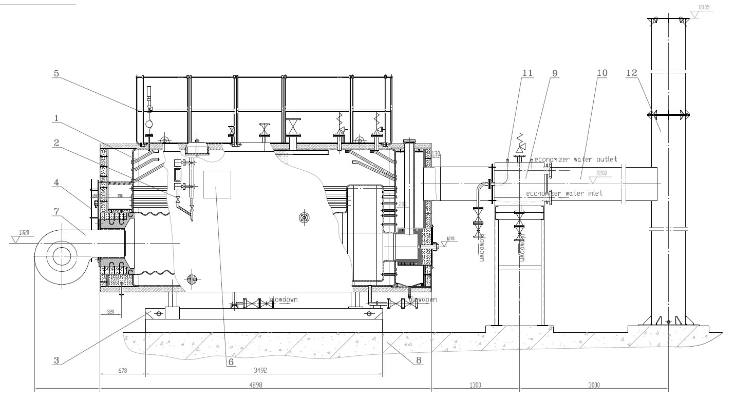
How Does Flue Gas Heat Recovery (Economizers, Air Preheaters) Improve Thermal Efficiency?
Combustion systems in boilers and furnaces typically waste a significant portion of energy in the form of hot flue gases escaping the stack. These gases still contain usable thermal energy, but without a recovery system, this energy is lost to the environment. Economizers and air preheaters are heat recovery devices designed to capture that waste heat and transfer it back into the process—either by preheating feedwater or combustion air. The result? Reduced fuel demand, lower flue gas temperatures, and improved thermal efficiency. Integrating these systems is one of the most effective ways to increase overall energy performance without increasing fuel input.
Flue gas heat recovery improves thermal efficiency by capturing residual heat from exhaust gases and transferring it to feedwater (via economizers) or combustion air (via air preheaters). This reduces the fuel required to reach desired steam or heat outputs, as the system begins the process at a higher energy state. Heat recovery reduces stack losses, lowers flue gas temperature, and can improve overall boiler efficiency by 5% to 20%, depending on fuel type, system load, and recovery configuration.
In any fuel-fired process, flue gas heat recovery is not just a sustainability step—it’s a smart economic strategy.
Economizers and air preheaters reduce stack losses and improve boiler thermal efficiency.True
By capturing waste heat from flue gases and transferring it to water or air, these devices reduce the energy needed from fuel combustion.
🔁 How Flue Gas Heat Recovery Works
| Device | Target Medium | Energy Transfer Mechanism |
|---|---|---|
| Economizer | Feedwater | Transfers sensible heat from flue gas |
| Air Preheater | Combustion air | Transfers heat from flue gas to air |
These devices are installed in the flue gas path after the combustion chamber but before the stack, intercepting heat that would otherwise be wasted.
Diagram of Heat Flow:
Fuel + Air → Combustion → Hot Gases →
→ Heat Exchanger (Economizer/Preheater) →
→ Recovered Heat to Feedwater/Air →
→ Cooler Flue Gases to Stack
Flue gas heat recovery is not viable for modern high-efficiency boilers.False
Even modern boilers benefit from heat recovery, as flue gas still exits at temperatures far above the required levels for water or air heating.
📉 Effect on Thermal Efficiency
| Flue Gas Temp Before Recovery (°C) | After Recovery (°C) | Feedwater/Air Temp Increase (°C) | Efficiency Gain (%) |
|---|---|---|---|
| 230 | 140 | +35 (air), +40 (water) | 6–8% |
| 200 | 110 | +50 (water) | 9–12% |
| 170 | 90 | +60 (air) | 13–15% |
| 140 (condensing) | 55 | +70 | 16–20% |
Efficiency gain depends on:
Initial flue gas temperature
Type of fuel (natural gas, oil, biomass)
System load and feedwater return temperature
Surface area and configuration of the heat recovery device
🔧 Types of Heat Recovery Devices
| Device Type | Application | Key Benefit |
|---|---|---|
| Bare Tube Economizer | Standard gas and oil boilers | Simple and durable |
| Finned Tube Economizer | Compact, high surface area | High heat recovery in tight space |
| Condensing Economizer | Natural gas systems | Captures latent and sensible heat |
| Rotary Air Preheater (RAPH) | Large utility boilers | Efficient and continuous recovery |
| Tubular Air Preheater | Smaller industrial units | Easier maintenance, high flow rates |
🧪 Case Study: Textile Mill Boiler Retrofit
A textile plant with a 6 TPH natural gas boiler installed a finned tube economizer and a tubular air preheater.
Pre-Retrofit:
Flue gas temp: 240°C
Feedwater temp: 60°C
O₂ level: 5.5%
Fuel usage: 9,600 m³/day
Post-Retrofit:
Flue gas temp: 135°C
Feedwater temp: 95°C
Combustion air temp: 120°C
Fuel usage: 8,300 m³/day
Efficiency gain: 12.6%
Annual savings: ~$64,000
Condensing economizers can improve efficiency by recovering both sensible and latent heat from flue gases.True
Condensing economizers operate below the dew point, allowing them to recover additional energy from moisture in the flue gas.
📋 Advantages of Flue Gas Heat Recovery
| Benefit | Description |
|---|---|
| Reduced Fuel Consumption | Less energy needed to heat feedwater or air |
| Lower Flue Gas Temperature | Reduces stack losses and thermal pollution |
| Improved Steam Production | Quicker pressure ramp-up and higher throughput |
| Enhanced Combustion | Preheated air supports flame stability |
| Emissions Reduction | Lower fuel use means less CO₂, NOₓ, and CO |
| Lower O₂ in Flue Gas | More complete combustion, less unburned fuel |
📊 Impact by Fuel Type
| Fuel Type | Recovery Potential | Common Recovery Device |
|---|---|---|
| Natural Gas | High (condensing) | Condensing economizer + air preheater |
| Heavy Fuel Oil | Medium | Non-condensing economizer |
| Biomass | Medium–High | Ash-resistant tubular preheater |
| Coal | Medium | Rotary or regenerative air preheater |
In systems burning high-moisture fuels, such as biomass or RDF, flue gas heat recovery also helps evaporate fuel moisture, improving combustion quality.
🧠 Monitoring and Controls for Optimal Performance
| Technology | Role |
|---|---|
| Flue Gas Temp Sensors | Ensure target heat recovery is achieved |
| O₂ Trim Systems | Optimize combustion and minimize excess air |
| Condensate Drainage Controls | Manage acidic water in condensing systems |
| Fouling Detectors | Alert when heat exchanger surfaces need cleaning |
| SCADA or PLC Integration | Automates adjustments for dynamic loads |
Maintenance is essential to ensure heat exchanger surfaces remain clean and effective, especially in ash-laden systems.
Summary
Flue gas heat recovery through economizers and air preheaters offers one of the most effective and affordable pathways to increase thermal efficiency in combustion systems. By reclaiming waste heat and using it to preheat feedwater or combustion air, these systems reduce fuel consumption, improve combustion quality, and lower emissions. With potential efficiency gains of 5–20%, flue gas heat recovery is a proven, scalable solution for any boiler or furnace operator aiming to lower energy costs and improve performance. In thermal systems, the energy you reuse is the energy you don’t have to buy.
How Do Automation, Diagnostics, and Predictive Maintenance Lower Operational Risks?
In industrial combustion and thermal systems, equipment failures and process disruptions can result in significant losses—from fuel waste and unplanned downtime to costly repairs and safety hazards. Traditional maintenance strategies, such as time-based or reactive approaches, leave operations vulnerable to unexpected breakdowns. Fortunately, modern automation, real-time diagnostics, and predictive maintenance technologies enable operators to anticipate and prevent failures before they occur, lowering risk and improving system resilience.
Automation, diagnostics, and predictive maintenance lower operational risks by continuously monitoring system performance, identifying early warning signs of faults, and enabling proactive interventions. Automation ensures process stability by reducing human error and maintaining optimal operating parameters. Diagnostics use real-time data to detect anomalies, while predictive maintenance leverages historical trends and machine learning to forecast failures. These strategies minimize unplanned downtime, reduce maintenance costs, extend equipment life, and enhance operational safety and reliability.
Smart, data-driven systems don’t just react—they predict, protect, and prevent.
Predictive maintenance reduces operational risks by identifying equipment issues before failure occurs.True
By using real-time and historical data to predict failures, predictive maintenance enables proactive repair and prevents unplanned outages.
🤖 The Role of Automation in Operational Risk Reduction
| Function | Automation Role | Risk Reduction Impact |
|---|---|---|
| Air-Fuel Ratio Control | Maintains optimal combustion | Prevents fuel waste and unstable flames |
| Boiler Load Control | Adjusts firing rate based on demand | Avoids overpressure and low-load cycling |
| Alarm and Shutdown Logic | Triggers safety actions on critical faults | Prevents catastrophic failure or explosions |
| Feedwater and Pressure Control | Ensures consistent steam output | Protects turbines, heat exchangers, and pipes |
| Combustion Optimization | Reduces emissions and energy use | Improves compliance and efficiency |
By replacing manual intervention with logic-driven control systems, human error is minimized, and response times are greatly improved.
Automation reduces human error and speeds up fault response times in industrial systems.True
Automated systems consistently manage processes and respond faster than manual operations, preventing process deviation and failure.
🔍 Diagnostics: Real-Time Fault Detection
Diagnostics refer to the detection, analysis, and interpretation of system anomalies using sensor data and analytics tools.
Examples of Diagnostic Parameters:
| Parameter | Measured By | What It Detects |
|---|---|---|
| O₂ and CO Levels | Flue gas analyzers | Incomplete combustion, burner malfunction |
| Vibration | Accelerometers | Pump or motor bearing wear |
| Temperature Drift | Thermocouples, IR cameras | Fouling, insulation loss, hot spots |
| Pressure Drop | Differential pressure sensors | Tube fouling or blockage |
| Stack Temperature | Thermocouples | Heat exchanger inefficiency, soot buildup |
Early detection enables operators to correct problems before they escalate, avoiding unscheduled downtime.
🧠 Predictive Maintenance: From Data to Prevention
Predictive maintenance uses AI, machine learning, and historical trends to forecast when components are likely to fail and schedule maintenance accordingly.
| Technology | Use Case | Predictive Benefit |
|---|---|---|
| Digital Twins | Simulate real-time equipment behavior | Test “what-if” failure scenarios |
| Machine Learning Models | Analyze past failures to predict future issues | Prevent unplanned outages |
| Condition-Based Monitoring | Track wear indicators in real time | Extend equipment service life |
| SCADA with Analytics | Centralize data for trend analysis | Support risk-informed decision-making |
In one study, predictive maintenance reduced unscheduled downtime by up to 45% and maintenance costs by 30–40% annually.
Predictive maintenance increases overall maintenance costs due to more frequent repairs.False
It reduces costs by replacing parts only when necessary, avoiding unnecessary preventive maintenance and emergency repairs.
📉 Operational Risks Without Smart Monitoring
| Operational Risk | Root Cause | Resulting Consequence |
|---|---|---|
| Unplanned Shutdown | Undetected component failure | Lost production, restart delays |
| Safety Incident | Overpressure or flame instability | Injury, regulatory penalties |
| Fuel Waste | Faulty burners or airflow imbalance | High operating cost, high emissions |
| Heat Exchanger Rupture | Fouling or scaling left unchecked | Equipment damage, steam leaks |
| Environmental Violation | Emission spike from inefficient combustion | Fines, permit suspension |
Each failure not only increases cost, but also undermines reliability, sustainability, and stakeholder confidence.
🧪 Case Study: Chemical Plant Boiler Optimization
A 30 TPH gas-fired boiler was prone to CO spikes, refractory failures, and emergency shutdowns.
Challenges:
No combustion feedback loop
No predictive failure tracking
Reactive maintenance only
Implemented:
Real-time combustion diagnostics
Predictive maintenance software for burner nozzles
PLC-integrated alarm logic
Results:
Unplanned shutdowns reduced by 60%
Fuel use optimized (O₂ trimmed from 6.2% to 3.4%)
Maintenance labor costs down by 33%
98.7% equipment availability achieved
AI-driven predictive systems help prioritize maintenance activities based on actual risk levels.True
They assess component health and recommend actions, reducing downtime and focusing resources where most needed.
📋 Comparison: Maintenance Strategies
| Strategy | Trigger | Pros | Cons |
|---|---|---|---|
| Reactive | After failure | Low upfront cost | High downtime, costly emergencies |
| Preventive | Time or usage interval | Predictable scheduling | May replace parts unnecessarily |
| Predictive | Based on condition and trends | Optimized resource use, fewer failures | Requires sensor/data infrastructure |
Predictive strategies offer the best balance between cost, uptime, and reliability—especially for large-scale combustion systems.
Summary
Automation, diagnostics, and predictive maintenance are essential tools for reducing operational risks in modern combustion and thermal systems. They eliminate guesswork, minimize failure impacts, and enable proactive management of assets. Real-time monitoring and intelligent controls maintain process stability, while data-driven analytics ensure timely interventions and extend equipment life. The result is lower fuel use, fewer shutdowns, improved safety, and better long-term ROI. In today’s high-demand energy environment, your best defense against failure is foresight powered by data.
🔍 Conclusion
Optimizing a Circulating Fluidized Bed boiler system requires an integrated approach that aligns fuel properties, combustion control, air management, and heat recovery. When properly maintained and tuned, CFB boilers deliver stable, efficient, and low-emission performance—even with low-grade or variable fuels. By addressing these efficiency drivers and integrating smart controls, operators can realize significant savings in fuel, maintenance, and emissions-related costs.
📞 Contact Us
💡 Need expert help optimizing your CFB boiler? Our engineering team offers fuel analysis, bed fluidization tuning, heat recovery integration, and maintenance planning customized to your operating conditions.
🔹 Contact us today and turn your CFB boiler into a high-efficiency, low-cost power solution! 🔄🔥📉
FAQ
What are the top strategies to optimize CFB boiler performance?
Key strategies include:
Maintaining optimal bed temperature (typically 800–900°C)
Balancing primary and secondary air distribution
Controlling fluidization velocity
Monitoring and adjusting fuel feed rate
Implementing advanced control systems for air-fuel ratio and bed pressure
How does bed temperature affect combustion efficiency in a CFB boiler?
Bed temperature must be kept within the ideal range to ensure complete combustion while minimizing NOx formation and avoiding ash agglomeration. Deviations can cause incomplete burning or operational instability.
What role does fuel management play in CFB boiler cost reduction?
CFB boilers can burn a wide range of fuels—including biomass, coal, petcoke, and waste. Proper fuel blending, pre-drying, and sizing enhance combustion stability, reduce unburned carbon, and lower fuel costs per unit of steam generated.
How can heat recovery systems improve efficiency and reduce fuel consumption?
Installing economizers, air preheaters, and steam reheaters helps recover waste heat from flue gas, improving thermal efficiency by 5–10%. This lowers the boiler’s fuel demand and reduces emissions.
What maintenance practices ensure consistent boiler performance?
Frequent inspection and cleaning of cyclone separators and heat exchanger surfaces
Monitoring for erosion of tubes and refractory wear
Calibrating pressure, temperature, and O₂ sensors regularly
Maintaining proper ash handling and removal systems
These actions reduce unplanned downtime and ensure optimal combustion and heat transfer.
References
CFB Boiler Optimization and Operation Manual – https://www.energy.gov
Combustion Control in Fluidized Bed Boilers – https://www.sciencedirect.com
Advanced CFB Fuel Management Techniques – https://www.researchgate.net
Thermal Efficiency in Industrial Boilers – https://www.epa.gov
Heat Recovery Solutions in CFB Plants – https://www.bioenergyconsult.com
Air Distribution and Combustion Efficiency in CFBs – https://www.mdpi.com
CFB Boiler Maintenance Best Practices – https://www.energysavingtrust.org.uk
Boiler Performance Monitoring Technologies – https://www.automation.com
Fluidization and Fuel Flexibility in CFB Boilers – https://www.iea.org
CFB Boiler Emissions and Efficiency Trends – https://www.asme.org

Andy Zhao

Wade Zhang
How to Optimize Circulating Fluidized Bed Boiler Performance for Lower Operating Costs Read More »

")


")
-scaled.jpg)


(1)")


")