Industry News

What Are the Key Components of a Power Plant Boiler?

What Are the Key Components of a Power Plant Boiler?

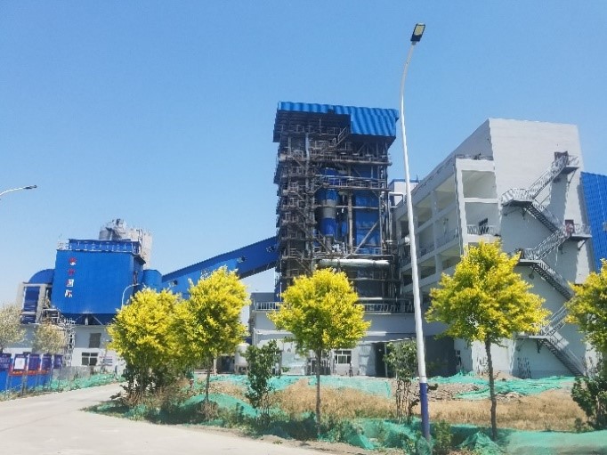
Power plant boilers are the heart of modern energy production, converting fuel into steam that drives turbines to generate electricity. However, due to the high temperatures, pressures, and continuous load demands, these systems must operate with precision and reliability. Without a clear understanding of their key components, operators risk reduced efficiency, safety hazards, and costly unplanned outages. Mastering the structure of a power plant boiler is crucial for ensuring optimal energy output, long-term durability, and environmental compliance.

The key components of a power plant boiler include the furnace (or combustion chamber), water walls, superheater, reheater, economizer, air preheater, and control system. These elements work together to ensure efficient fuel combustion, effective heat transfer, and reliable steam production for turbine operation. Modern power boilers also incorporate advanced emission control systems to reduce pollutants and meet regulatory standards.

Understanding how each of these components functions—and how they interact—is essential for improving performance, reducing operational costs, and maintaining safe, continuous energy generation.
What is the role of the furnace in a power plant boiler?

![Power Plant Boiler Furnace Section]
Prompt: Power plant boiler furnace section + cutaway diagram showing flame, water walls, and combustion process + large-scale industrial setting + realistic technical rendering + dynamic and energetic mood + high-temperature lighting effects

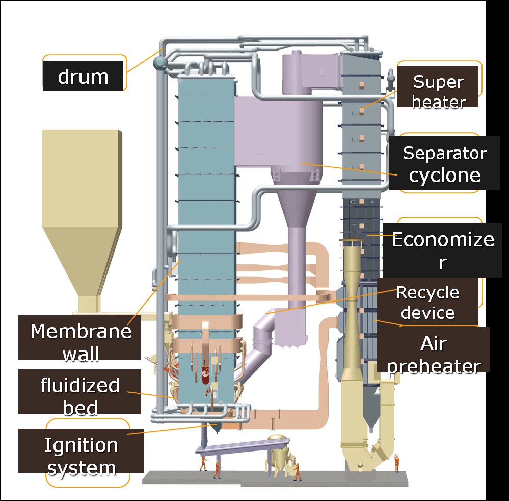
In thermal power generation, the furnace is the heart of the boiler system—the location where the fuel’s chemical energy is first transformed into usable heat. If the furnace is poorly designed, mismanaged, or damaged, combustion becomes inefficient, fuel is wasted, emissions increase, and the boiler may suffer critical failures. As such, the performance of the furnace has a direct impact on a power plant’s thermal efficiency, operational stability, and environmental compliance. To maintain reliable steam production, consistent fuel combustion, and safety, understanding the furnace’s function is essential.

The furnace in a power plant boiler serves as the primary combustion chamber where fuel—such as coal, gas, oil, or biomass—is burned to release thermal energy. This heat is transferred to surrounding water walls, converting water into high-pressure steam. The furnace plays a vital role in flame stabilization, heat generation, emission control, and energy transfer efficiency, forming the foundation of the entire power generation cycle.

Whether in pulverized coal-fired units, circulating fluidized bed (CFB) boilers, or gas-fired systems, the furnace must be optimized to support high combustion efficiency, low emissions, and structural integrity under extreme conditions.

Functional Role of the Furnace in the Boiler System

FunctionDescription
Combustion of FuelProvides the controlled environment where fuel is ignited and burned
Heat GenerationProduces the thermal energy needed to generate steam
Radiant Heat TransferTransfers energy through radiation to water-cooled furnace walls
Flame StabilizationMaintains steady flame shape and location for safe and efficient combustion
Emission Formation ControlImpacts formation of pollutants like NOx, CO, and unburned carbon

The furnace is lined with membrane water walls made of steel tubes, which absorb most of the radiant heat and convert water into steam. The size, shape, and design parameters of the furnace directly influence how well this heat transfer occurs.

Types of Furnaces in Power Plant Boilers

Furnace TypeDescriptionCommon Fuel Type
Pulverized Fuel FurnaceBurns finely ground coal with tangential or wall-mounted burnersCoal
Fluidized Bed FurnaceUses air to suspend fuel particles in a turbulent bedBiomass, coal, waste
Oil/Gas-Fired FurnaceBurns atomized fuel in a flame envelopeNatural gas, diesel
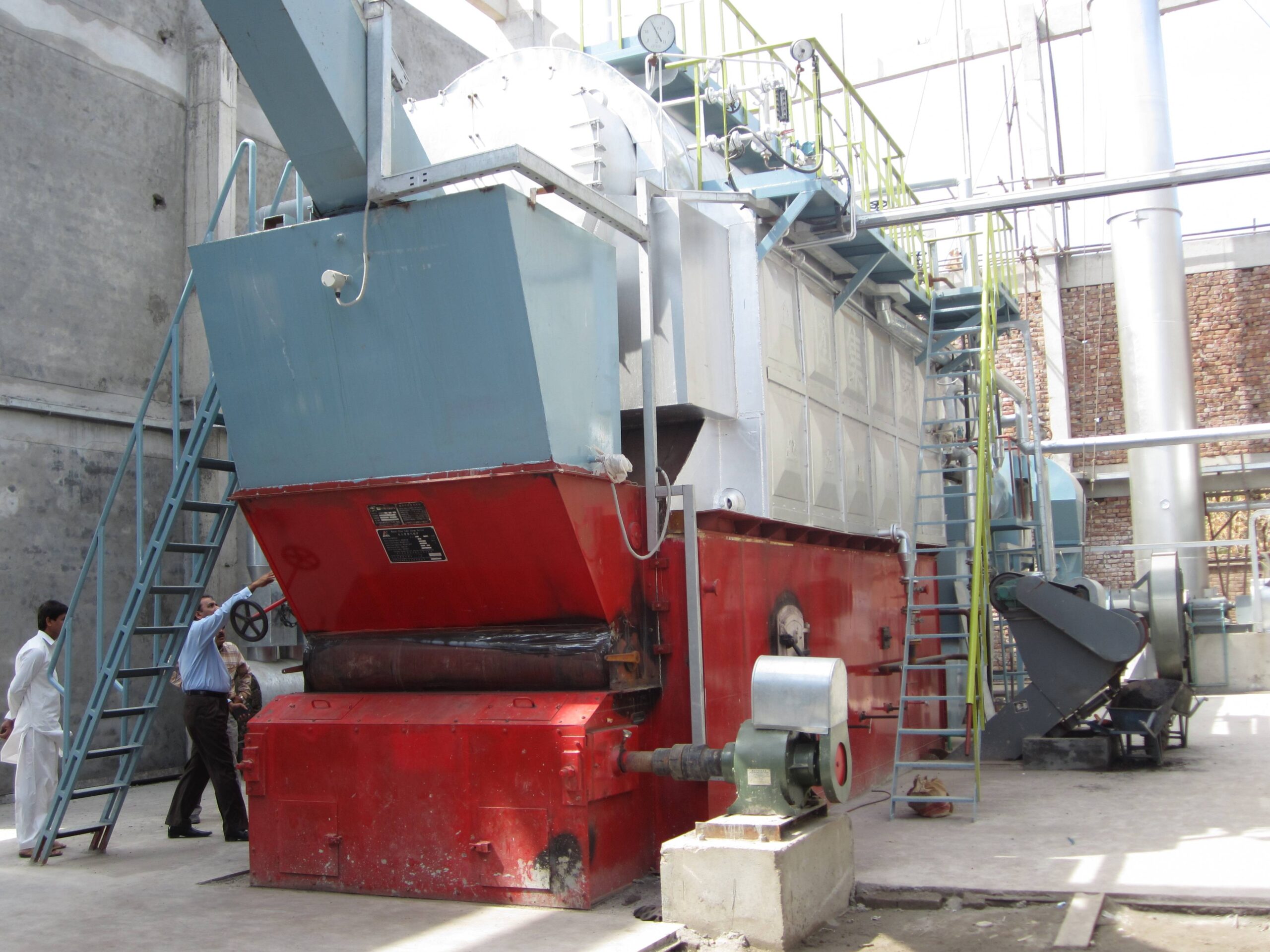
Stoker FurnaceUses mechanical grates for solid fuel combustionWood, coal, waste biomass

Each type is engineered based on fuel characteristics, heat demand, and plant load flexibility.

Thermal and Combustion Dynamics

The furnace must provide three essential elements for combustion, often known as the “fire triangle”:

  1. Fuel – Solid, liquid, or gaseous

  2. Oxygen (from air) – Supplied by forced or induced draft fans

  3. Heat (Ignition Source) – Ignition via burners or pilot flame

Key parameters that influence furnace performance:

ParameterOptimal RangeEffect on Operation
Combustion Temp1,200–1,500°C (coal/gas/oil)Affects flame stability and NOx formation
Residence Time1–2 secondsDetermines completeness of combustion
Excess Air10–20% above stoichiometricEnsures complete combustion but lowers efficiency if too high
Furnace Exit Gas Temp (FEGT)900–1,200°CImpacts heat transfer and slagging risk

Heat Transfer and Energy Conversion Role

The furnace contributes approximately 40–50% of the total heat absorbed in a boiler. This occurs primarily via radiation, as opposed to the convection-dominated zones downstream (e.g., superheaters and economizers).

Heat Transfer ZoneMechanismContribution (%)
Furnace (Water Walls)Radiation45–50%
Superheater, ReheaterConvection20–30%
EconomizerConvection10–15%
Air PreheaterConvection5–10%

Water circulating in the furnace walls absorbs heat and turns into saturated steam. In once-through and high-pressure boilers, this steam goes directly to the superheater.

Emissions Control via Furnace Design

The furnace design can significantly reduce pollutant formation at the source. For example:

  • Low-NOx burners and staged combustion control the flame temperature and oxygen availability to reduce nitrogen oxide formation.

  • Flue Gas Recirculation (FGR) lowers flame temperature and dilutes combustion gases.

  • Sorbent injection inside fluidized bed furnaces captures SO₂ during combustion.

PollutantFormation ZoneMitigation Strategy
NOxHigh-temperature flameStaged air, low-NOx burners, FGR
COIncomplete combustionProper air-fuel ratio and residence time
SO₂From sulfur in fuelLimestone injection or post-treatment
PMUnburned particlesBetter burnout and furnace exit controls

Design Considerations and Best Practices

A well-designed furnace must address the following:

Design FactorImportance
Furnace VolumeMust allow sufficient residence time for combustion
Height-to-Width RatioAffects heat flux and flame path
Water Wall Surface AreaDictates heat absorption capacity
Slagging and Fouling ControlPrevents heat transfer losses and corrosion
Material SelectionHandles high temperatures and corrosive gases

In CFB boilers, the furnace is typically taller and narrower to allow for vertical fluidization and particle recirculation, which further enhances combustion efficiency and reduces unburned carbon.

Monitoring and Control of Furnace Operations

Modern power plants use control systems to manage furnace conditions via:

  • Bed/furnace temperature sensors

  • Flame scanners for burner operation

  • Pressure differential monitoring

  • Continuous Emission Monitoring Systems (CEMS)

  • Furnace Exit Gas Temperature (FEGT) thermocouples

These tools feed data into DCS (Distributed Control Systems) to adjust:

  • Burner firing rate

  • Air/fuel ratio

  • Feedwater flow

  • Sootblower operation

Summary: Furnace as the Energy Core

RoleFunction
Combustion ChamberConverts fuel to heat energy
Radiant Heat Transfer ZoneTransfers heat to water walls to generate steam
Flame StabilizationMaintains safe and efficient combustion
Emission Formation SiteDetermines NOx, CO, SOx levels based on design and control
Steam Generation SourceSupplies energy for turbine-driven power generation

In short, the furnace is where the transformation of fuel into usable thermal energy begins. Its performance governs not just steam output, but the entire thermal efficiency and environmental footprint of the power plant. With advances in design, materials, and automated control, modern furnace systems continue to be the centerpiece of reliable and sustainable power production.
How do water walls contribute to steam generation and heat absorption?

![Water Wall Tubes in a Power Plant Boiler]
Prompt: Industrial water wall tubes inside a boiler furnace + high-resolution cutaway diagram + showing radiant heat transfer to water-filled steel tubes + flames and combustion zone in background + large-scale power plant setting + thermal-focused atmosphere + intense warm lighting

In the heart of every power plant boiler, the efficient conversion of fuel energy into steam begins with radiant heat transfer. If this step is compromised—through inadequate heat absorption or poor circulation—the boiler’s efficiency suffers, steam output drops, and risk of overheating or failure increases. Water walls, also known as furnace walls or membrane walls, are the primary surfaces responsible for absorbing the radiant heat from combustion inside the furnace. These vertical tube panels line the boiler’s interior, playing a vital role in energy capture and steam generation.

Water walls in a boiler are heat-absorbing tube panels that form the internal walls of the furnace, capturing radiant energy emitted by fuel combustion and converting feedwater inside them into steam or high-temperature water. Their function is critical for efficient thermal absorption, maintaining uniform furnace temperature, initiating the water-to-steam phase change, and supporting overall boiler efficiency and safe operation.

Understanding the mechanics of how water walls work is essential for engineers, plant operators, and maintenance teams to optimize steam generation and protect boiler integrity in high-temperature environments.

Structural and Thermal Function of Water Walls

Water walls are comprised of vertical steel tubes that are either:

  • Bare tubes (in older designs), or

  • Membrane walls: Tubes joined by steel membranes welded in between to form gas-tight furnace walls (modern design standard)

FeatureFunction
Water-Cooled SurfaceAbsorbs radiant energy from combustion flame
Heat Exchange MediumWater or steam-water mixture flows inside the tubes
Steam Generation Start PointWater begins phase change due to intense heat
Structural SupportForms the pressure boundary and furnace enclosure

These walls form the boundary of the furnace and are directly exposed to the intense radiation emitted by burning fuel (temperatures often exceeding 1,200–1,500°C).

Heat Transfer Mechanism

Radiant heat transfer from the flame to the water wall tubes follows Stefan-Boltzmann law, where radiation increases exponentially with temperature. In water walls:

  • Radiation is the dominant heat transfer mode (not convection)

  • Heat flux can range from 150–300 kW/m² depending on furnace size and fuel

  • Water or steam-water mixture inside the tubes carries the heat away to the steam drum or separators

Heat Absorption Process

  1. Water enters the water wall tubes from the bottom headers (cold-end).

  2. As water ascends the tube, radiant heat is absorbed, and temperature rises.

  3. At certain point (saturation temp), phase change begins—water starts turning to steam.

  4. Mixture of water and steam exits the top header and goes to the steam drum for separation.

Region of Water Wall TubeThermal State of Water
BottomSubcooled liquid
MiddleSaturated boiling mixture
TopSteam-water mixture

Contribution to Steam Generation

Water walls are responsible for 35% to 50% of the total steam generation in a large utility boiler, particularly due to:

  • High heat absorption area: Vertical panels line four furnace walls

  • Long exposure time: Tall furnaces increase residence time for heat exchange

  • Optimized flow rate: Designed to match mass flow and boiling characteristics

Design Parameters and Operating Conditions

ParameterTypical Range
Tube Diameter38–76 mm (outer)
Tube MaterialCarbon steel, alloy steel
Wall Thickness3–6 mm
Pressure RatingUp to 300 bar
Water Flow Velocity1–3 m/s
Heat Flux Exposure150–300 kW/m²
Wall Temperature350–500°C (outer wall)

In high-pressure, once-through boilers (like in supercritical power plants), water walls serve as evaporator circuits, and the entire steam generation process begins and completes inside these tubes before entering the superheater.

Types of Water Wall Designs

TypeCharacteristicsApplications
Bare Tube WallsOlder design, gaps between tubes, less efficientLow-pressure boilers
Membrane WallsTubes joined by metal fins/membranes, gas-tight enclosureModern utility & industrial boilers
Tangentially Fired Furnace WallsDesigned for corner-firing flame patternsPulverized coal units
Spiral and Vertical PanelsFor once-through designs; promote stable flowSupercritical boilers

Performance Impact: Efficiency and Safety

A. Efficiency Contributions

  • Absorbs up to 50% of total furnace heat input

  • Reduces heat load on superheaters and economizers

  • Improves boiler thermal efficiency by preventing energy loss to refractory walls

B. Safety Enhancements

  • Prevents furnace wall overheating and material failure

  • Ensures uniform heat absorption to avoid hot spots

  • Forms gas-tight barrier to contain combustion gases and protect the boiler casing

Monitoring and Maintenance Best Practices

ActionPurpose
Thermal imaging scansDetect hot spots or tube overheating
Thickness testing (UT)Monitor for tube erosion or corrosion
Inspection of headers and weldsIdentify cracking or joint degradation
Boiler blowdown and water chemistry controlPrevent internal scaling/fouling
Proper circulation designPrevents tube dry-out and heat flux imbalance

Inadequate water flow or poor thermal transfer can lead to boiler tube failure, steam blanketing, and dangerous thermal stresses, which is why regular monitoring is essential.

Summary of Water Wall Functions

Function AreaContribution of Water Walls
Steam GenerationInitiates phase change of feedwater via radiant heat
Thermal AbsorptionCaptures majority of radiant furnace energy
Pressure ContainmentForms part of the boiler pressure boundary
Combustion EnclosureMaintains furnace geometry and isolates heat
Safety AssurancePrevents flame impingement on boiler casing

Water walls are not just passive components—they are active, high-performance elements that define the boiler’s ability to efficiently and safely produce steam under extreme conditions. Their proper design, operation, and maintenance are critical to modern thermal power generation.
What are superheaters and reheaters, and how do they improve steam quality?

![Superheaters and Reheaters in Power Plant Boilers]
Prompt: Industrial superheaters and reheaters inside a power plant boiler + high-temperature steam tubes with radiant and convective zones + labeled cross-section showing steam flow + realistic thermal engineering setting + high-tech atmosphere + glowing orange lighting

In thermal power generation, the quality and efficiency of steam directly impact the performance of turbines, overall plant output, and fuel economy. Saturated steam generated in the boiler drum contains moisture, which can cause erosion, inefficiency, and mechanical damage in turbine blades. To overcome this, superheaters and reheaters are integrated into modern boiler systems. Without them, steam turbines would operate with lower thermal efficiency and require more frequent maintenance. These heat exchanger components raise steam temperature well above saturation, significantly improving energy transfer, system reliability, and efficiency.

Superheaters and reheaters are heat exchanger components in power plant boilers that elevate the temperature of steam beyond its saturation point without increasing pressure. Superheaters convert saturated steam into dry or superheated steam before it enters the high-pressure turbine, while reheaters reheat partially expanded steam exiting the high-pressure turbine for reuse in the intermediate or low-pressure turbine stages. Together, they improve steam quality, reduce turbine moisture content, increase cycle efficiency, and enable higher thermal outputs.

Both components are crucial for plants using Rankine or combined-cycle systems, particularly in high-capacity steam turbines where even small improvements in steam quality can lead to large gains in power generation efficiency and durability.

Superheaters: Structure, Function, and Role

Superheaters are positioned in the convective and radiant zones of the boiler and are made up of tube bundles that absorb heat from flue gases to increase steam temperature. The steam entering a superheater is saturated (wet) steam, and it exits as superheated (dry) steam, with a temperature up to 540°C or higher.

ParameterTypical Range
Inlet Steam Temp~300–350°C (saturated steam)
Outlet Steam Temp500–600°C (superheated)
Steam Pressure100–250 bar (depending on boiler)
Heat SourceRadiant + convective flue gas
LocationUpper furnace, flue gas pass

Benefits of Superheating:

  • Increases turbine efficiency by raising enthalpy drop across stages

  • Prevents blade erosion by eliminating moisture

  • Allows higher power output from same mass flow

  • Supports dry expansion, improving turbine life

Types of Superheaters

TypeDescriptionApplication
Radiant SuperheaterAbsorbs heat directly from furnace radiationHigh-temperature boost zone
Convective SuperheaterLocated in flue gas path, uses convection heatingSecondary superheating or control
Platen SuperheaterPositioned near the upper furnace, facing the flameHandles large heat loads
Pendant/HorizontalHung in convection path for additional heat pickupStabilizes final outlet temperature

Reheaters: Function and Thermodynamic Impact

After high-pressure steam expands in the high-pressure (HP) turbine, it loses energy and becomes partially wet. This partially expanded steam is routed back into the reheater, where it is reheated before being sent into the intermediate-pressure (IP) or low-pressure (LP) turbine for further expansion.

Reheater RoleDescription
Inlet Steam QualityPartially wet, ~300–400°C
Outlet Steam TemperatureReheated to ~500–560°C
Cycle IntegrationBetween HP and IP/LP turbine stages
Main BenefitMaintains dryness of steam throughout turbine path

Advantages of Reheating:

  • Avoids moisture condensation in turbine LP stages

  • Enhances thermodynamic efficiency of Rankine cycle

  • Reduces blade corrosion and wear

  • Enables multiple expansion stages for higher output

Performance Improvement via Superheaters and Reheaters

AspectSaturated Steam CycleSuperheated/Reheated Cycle
Thermal Efficiency~30–35%~38–45%
Steam Turbine DamageHigher risk (due to moisture)Significantly reduced
Specific Steam ConsumptionHigher (~4.5 kg/kWh)Lower (~3.5 kg/kWh)
Enthalpy DropLimitedMaximized (better energy extraction)
Boiler Output QualityWet steamDry, high-energy steam

Thermodynamic Visualization: T-s Diagram

T (Temperature)
|
|               _______
|             /        \
|            /          \
|        A–>B            C–>D
|       (Superheat)      (Reheat)
|     /                      \
|    /                        \
|___/                          \_________ S (Entropy)
  • A–B: Superheating of saturated steam

  • C–D: Reheating after partial expansion
    This improves the Mean Temperature of Heat Addition, increasing cycle efficiency.

Material and Design Considerations

Because of the extremely high temperatures and pressures, superheaters and reheaters must be built from high-grade materials:

ComponentMaterial ExamplesPurpose
TubesSA213 T91, Inconel, austenitic steelResist creep, corrosion, and stress
Supports & HangersAlloy steel with expansion featuresHandle thermal movement
HeadersForged steelWithstand high pressure/temperature

Proper thermal expansion management is essential. These components expand several centimeters under load and must be allowed to move without causing stress fractures.

Control and Monitoring in Operation

Control ElementRole
Attemperators (Desuperheaters)Regulate steam temperature by spraying water
Thermocouples/RTDsMonitor tube wall and steam temps
Flow Measurement DevicesEnsure uniform steam distribution
Bypass SystemsDivert flow during startup or maintenance

Common Challenges and Mitigations

IssueSolution/Prevention
Overheating or tube failureAccurate temp control, proper water chemistry
Thermal stress crackingExpansion joints, controlled ramp-up
Steam temperature fluctuationMulti-stage attemperation and feedback

Summary: How They Improve Steam Quality

ComponentFunctionImpact on Performance
SuperheaterIncreases steam temperature above saturationHigher turbine efficiency, dry steam
ReheaterReheats partially expanded steamExtends expansion process, prevents moisture
Combined EffectImproves thermodynamic efficiencyReduces fuel use, emissions, and turbine wear

In conclusion, superheaters and reheaters are fundamental components of high-performance power plant boilers. They upgrade raw steam into a powerful, dry, and efficient medium capable of delivering maximum energy to turbines with minimal wear. Without them, modern thermal power generation would be significantly less efficient and far more costly to maintain.
How does the economizer enhance thermal efficiency in a power plant boiler?

![Boiler Economizer Heat Recovery System]
Prompt: Economizer heat exchanger in a power plant boiler + cross-sectional industrial diagram + showing feedwater flowing through finned tubes and flue gas stream + steam generator background + technical environment + energy-efficient mood + warm industrial lighting

In thermal power plants, maximizing energy extraction from every kilogram of fuel is vital to improve efficiency and reduce emissions. A significant portion of energy from fuel combustion is lost through high-temperature flue gases. If not captured, this waste heat reduces overall boiler efficiency and increases fuel consumption. This is where the economizer comes into play. Positioned in the flue gas path, the economizer recovers sensible heat and uses it to preheat boiler feedwater—leading to substantial thermal savings and improved steam generation performance.

An economizer enhances the thermal efficiency of a power plant boiler by recovering residual heat from flue gases and transferring it to the incoming feedwater before it enters the boiler drum or evaporator section. This preheating process reduces the energy required to convert water into steam, thereby decreasing fuel consumption, lowering stack temperature, improving boiler responsiveness, and enhancing overall plant efficiency by 3–8%.

Economizers are essential components in coal, gas, oil, and biomass-fired boilers and are a proven solution for reducing operational costs and improving environmental compliance.

What Is an Economizer?

An economizer is a type of heat exchanger installed in the boiler flue gas duct after the combustion chamber but before the air preheater or stack. It consists of finned or bare tubes that carry boiler feedwater. As flue gases pass over the tube surface, their heat is transferred to the water inside.

ComponentFunction
Tubes (finned or smooth)Carry feedwater and absorb heat from flue gas
HeadersDistribute and collect water uniformly
Casing/DuctingEnsures controlled flue gas flow over heat transfer area
Drain & Vent SystemRemoves trapped air or condensate from water circuits

Economizers operate on the counterflow principle, where water and flue gases flow in opposite directions to maximize temperature gradient and heat transfer.

How the Economizer Improves Thermal Efficiency

The primary role of the economizer is to raise feedwater temperature before it enters the boiler drum or evaporator. This reduces the required fuel heat input for steam generation.

Efficiency Enhancement MechanismResult
Feedwater PreheatingLess energy needed in furnace to reach boiling point
Reduced Flue Gas TemperatureMinimizes heat loss through stack
Improved Heat UtilizationRecovers ~5–15% of energy lost in flue gas
Lower Fuel ConsumptionUp to 10% fuel savings depending on load/fuel
Shorter Startup TimesQuicker approach to boiling conditions

Performance Parameters of Economizers

ParameterTypical Range
Flue Gas Inlet Temp300–450°C
Flue Gas Exit Temp150–250°C
Feedwater Inlet Temp80–120°C
Feedwater Outlet Temp150–200°C
Heat Transfer Efficiency70–85%
Efficiency Gain (Overall Boiler)3–8%

Sample Energy Savings from Economizer Use

Plant Size (MW)Economizer Energy Recovery (kCal/hr)Annual Fuel Savings (tons)
50 MW~25 million~3,500
100 MW~50 million~7,200
300 MW~150 million~22,000

Types of Economizers

TypeDescriptionApplication
Bare Tube EconomizerSimple design with plain tubes; lower surface areaLow to medium-duty boilers
Finned Tube EconomizerEnhanced surface area using fins around tubesHigh-pressure, large boilers
Coil EconomizerCompact design for tight spacesPackage boilers
Condensing EconomizerRecovers latent heat from flue gas moisture (low temp)Natural gas and clean-burning fuels

Economizer in the Boiler Heat Path

Boiler Flow Path:
Combustion → Furnace (Radiant Heat) → Superheater → Reheater → Economizer → Air Preheater → Stack
                                                             ↑
                                                      Feedwater Flow
  • The economizer is the last step in the heat exchange path before the flue gas exits.

  • It is also the first point of heat gain for the feedwater entering the boiler.

Comparison: With vs Without Economizer

ParameterWithout EconomizerWith Economizer
Feedwater Inlet Temp60–90°C150–200°C
Flue Gas Exit Temp>300°C~200°C
Fuel ConsumptionHigherReduced by 5–10%
Boiler Thermal Efficiency78–82%85–88%
Stack Heat LossSignificantMinimized

Materials and Design Considerations

ComponentCommon MaterialReason
TubesCarbon steel, alloy steelHigh-temperature corrosion resistance
FinsStainless steel, aluminumHigh surface area, thermal conductivity
Support FramesMild steel with coatingsStructural durability

Economizers must also be designed to handle thermal expansion, soot accumulation, and acid dew point corrosion (especially in sulfur-containing fuels). Proper drainage and insulation are critical for long-term performance.

Operational Challenges and Maintenance

ChallengePrevention / Mitigation
Soot and ash foulingSootblowers or acoustic cleaning
Tube leakage or crackingProper water chemistry, inspection routines
Acid condensationMaintain flue gas temp above acid dew point (~150°C)
Flow imbalanceUniform header design and CFD modeling

Routine inspections and thermal imaging can help detect early signs of tube fouling or heat transfer degradation.

Integration with Boiler Control Systems

Modern economizers are monitored and controlled via DCS (Distributed Control Systems) and equipped with:

  • Temperature sensors (inlet/outlet water and gas)

  • Pressure transmitters

  • Flow meters

  • Bypass dampers (for load matching and emergency operation)

This integration enables dynamic optimization of energy recovery and protects the boiler against thermal imbalances.

Summary: Key Benefits of Economizers

BenefitDescription
Fuel EfficiencyReduces the need for fuel by recovering heat
Boiler Efficiency BoostIncreases total thermal efficiency by 3–8%
Emission ReductionLess fuel burned = fewer CO₂, SOx, and NOx emissions
Water PreheatingImproves heat absorption and reduces thermal shock
Extended Boiler LifeStabilizes boiler operation and reduces stress on components

The economizer is not just a supplementary device—it is a strategic component that bridges heat recovery with feedwater preconditioning. For any power plant aiming to enhance efficiency and reduce costs, an optimized economizer system is a critical investment.
What is the function of the air preheater in the boiler system?

![Air Preheater in Industrial Boiler System]
Prompt: Air preheater system in a thermal power plant boiler + cross-sectional diagram showing flue gas heating combustion air + rotary and tubular heat exchanger elements + clean industrial setting with labeled ducting and fans + high-efficiency mood + bright technical lighting

In a power plant boiler, maximizing combustion efficiency is crucial to optimize fuel use, reduce emissions, and boost overall thermal performance. However, if the combustion air enters the furnace at ambient or low temperatures, more fuel is needed to initiate and sustain the desired heat output. This not only increases operational costs but also causes more pollutants to be formed. The air preheater (APH) addresses this by utilizing residual heat from flue gases to preheat the incoming combustion air—resulting in improved efficiency, fuel savings, and reduced stack temperatures.

The air preheater in a boiler system functions as a heat recovery device that transfers residual heat from the flue gases to the incoming combustion air. By increasing the temperature of the air before it enters the furnace, the air preheater enhances fuel combustion efficiency, reduces fuel consumption, improves boiler thermal efficiency, and lowers exhaust gas temperature. It plays a vital role in boosting the overall energy balance and emission control of the boiler.

Let’s explore how the air preheater works, the types used in power plants, and its impact on boiler performance and environmental compliance.

How the Air Preheater Works

Air preheaters are installed at the exit of the economizer and before the flue gas stack, where the flue gas is still hot. Combustion air from the atmosphere is drawn in by forced draft (FD) fans and directed through the air preheater, where it absorbs heat from the outgoing flue gas.

Flow PathDescription
Flue Gas SideEnters air preheater after economizer at ~250–350°C
Air SideAmbient air enters and exits at ~120–200°C
Heat TransferConducted through tubes or plates between gas and air streams

This recovered heat reduces the fuel required to bring combustion air to ignition temperature, thus increasing combustion efficiency.

Types of Air Preheaters

TypeDescriptionCommon Application
Tubular Air PreheaterConsists of parallel tubes; flue gas outside, air inside or vice versaSmall to medium boilers
Rotary (Ljungström) Air PreheaterRotating matrix absorbs heat from flue gas and releases it to airLarge utility boilers
Plate-Type Air PreheaterStationary plates with alternating air and gas channelsCompact boilers, industrial systems

Key Design Elements

ComponentFunction
Heat Transfer MatrixProvides surface area for air and gas heat exchange
Sector PlatesSegregate air and gas flows in rotary units
Bearings & DrivesEnable rotation and sealing in rotary systems
DampersRegulate airflow and prevent pressure imbalances

Air Preheater Operating Parameters

ParameterTypical Range
Flue Gas Inlet Temp250–350°C
Flue Gas Exit Temp130–180°C
Air Inlet TempAmbient (~25–40°C)
Air Outlet Temp120–200°C
Heat Recovery Efficiency50–70%
Pressure Drop2–4 kPa (air side); 3–6 kPa (gas side)

Thermal Efficiency Enhancement

The air preheater improves boiler efficiency in the following ways:

  1. Preheating combustion air reduces fuel demand by lowering ignition lag.

  2. Flue gas temperature reduction recovers waste heat that would otherwise be lost.

  3. Improved flame temperature increases combustion completeness and reduces CO/NOx.

Boiler Efficiency MetricWithout APHWith APH
Boiler Thermal Efficiency82–85%86–89%
Specific Fuel ConsumptionHigherReduced
Stack Gas LossesHighLower
Startup TimeLongerShorter

Air Preheater in Boiler Heat Path

Furnace → Superheater → Reheater → Economizer → Air Preheater → Flue Stack
                                    ↑
                             Combustion Air → FD Fan → Air Preheater → Furnace

The APH sits at the end of the flue gas path and at the start of the air path, acting as the final opportunity to recover energy before the gases are released.

Emission Reduction and Environmental Role

Preheated combustion air enables:

  • Higher combustion temperatures = better burnout and lower CO

  • Stable air-fuel ratios = reduced formation of NOx and unburned hydrocarbons

  • Lower excess air requirements = minimized thermal losses

Sample Emission Improvements

PollutantTypical Reduction with APH
CO10–20%
NOx5–15%
SO₂ (indirect)Slight reduction due to less fuel burned

Challenges and Maintenance Considerations

ChallengeSolution or Mitigation
Ash and dust foulingUse sootblowers or rotary cleaning devices
Corrosion (acid dew point)Maintain flue gas outlet temp >130°C
Air leakage (rotary APH)Maintain seals and monitor differential pressures
Mechanical wear in rotary unitsSchedule inspections and replace seals/segments

Corrosion is particularly a risk when firing high-sulfur coal or biomass fuels that result in sulfuric acid condensation.

Monitoring and Integration

Modern APHs are equipped with:

  • Temperature sensors (inlet/outlet air and gas)

  • Pressure and flow meters

  • Seal leakage monitors (in rotary types)

  • Integration with DCS for combustion control optimization

Variable Frequency Drives (VFDs) on FD and ID fans allow dynamic control of air and gas flows to maintain optimal heat exchange.

Summary: Air Preheater’s Role in Boiler Performance

Function AreaContribution of Air Preheater
Fuel EfficiencyRecovers flue gas heat, reduces combustion fuel demand
Combustion StabilitySupplies warm air, supports complete fuel burn
Emission ControlEnables cleaner combustion with lower excess air
Thermal EfficiencyIncreases boiler output with less energy input
System IntegrationWorks with economizer and furnace for full-cycle optimization

The air preheater is more than just a supporting element—it is a critical energy recovery and efficiency component in any modern boiler system. Properly designed and maintained, it significantly enhances the sustainability and economic performance of thermal power generation.
How do control and emission systems optimize boiler performance and environmental compliance?

![Boiler Control and Emission Monitoring System in Industrial Plant]
Prompt: Boiler control and emission system integration + control panel with real-time data + stack emission monitoring equipment + digital interface with graphs and alerts + industrial boiler background + clean and efficient atmosphere + cool ambient lighting

In today’s power and industrial boiler systems, achieving high thermal efficiency alone is no longer sufficient. Regulatory pressure on air pollution, rising energy costs, and sustainability goals demand advanced solutions for both performance optimization and environmental compliance. Traditional boiler operations, when left to manual or isolated controls, often result in inefficient combustion, excessive emissions, fuel waste, and system failures. Modern control and emission systems work together to solve these issues—delivering automated precision, safety, and compliance with national and international environmental standards.

Control and emission systems in boiler operations function synergistically to optimize combustion, reduce fuel consumption, improve steam quality, and monitor/limit air pollutant emissions. Automated control systems use real-time sensor data and advanced logic to manage fuel-air ratios, temperature, pressure, and flow rates, while emission systems continuously track pollutants like NOx, SO₂, CO, and particulates, adjusting combustion and sorbent dosing to stay within permitted thresholds. This integrated approach ensures maximum thermal performance with minimal environmental impact.

This article explores how these systems function, their components, and the measurable benefits they deliver to both operational and environmental objectives.

Core Functions of Boiler Control and Emission Systems

System FunctionDescription
Combustion ControlMaintains ideal air-fuel ratio for efficient and complete combustion
Feedwater & Steam ControlRegulates pressure, drum level, and steam temperature
Oxygen Trim ControlAdjusts air input based on excess O₂ in flue gas
Emission Monitoring (CEMS)Continuously tracks NOx, SO₂, CO, O₂, and particulate levels
Flue Gas RecirculationReuses exhaust gases to reduce flame temperature and NOx formation
Sorbent Injection SystemsDoses limestone or activated carbon to neutralize SO₂ and mercury

Boiler Control Systems: Architecture and Optimization

Modern boilers rely on Distributed Control Systems (DCS) or Programmable Logic Controllers (PLC) to process signals from dozens or hundreds of sensors and execute coordinated control actions.

Key Subsystems:

SubsystemControlled Parameters
Combustion ManagementFuel feed, burner modulation, air dampers
Drum Level ControlFeedwater flow, steam outlet, drum level
Steam Temperature ControlAttemperator sprays, superheater bypass
Airflow ControlForced and induced draft fans, dampers
Load-Following ControlMatches boiler output to turbine or process demand

Advanced PID loops, fuzzy logic, and AI-based models are often integrated to ensure dynamic stability during transient loads.

Real-Time Performance Optimization

ParameterOptimization MethodBenefit
O₂ in Flue GasOxygen trim controlPrevents excess air, improves combustion
NOx FormationStaged combustion, low-NOx burnersLimits thermal NOx below regulatory limits
Steam TemperatureFeedforward control, attemperationProtects turbine, improves steam quality
Bed Pressure (CFB)Controls fluidization rateMaintains stable combustion in CFB systems
Fuel Moisture FluctuationAdaptive combustion logicPrevents flame instability, reduces CO

Emission Monitoring and Control Technologies

Regulatory agencies require Continuous Emissions Monitoring Systems (CEMS) for pollutants. These devices are typically installed in the stack and linked to the plant control network.

PollutantSource in BoilerControl Method
NOxHigh-temperature combustionStaged air, FGR, Low-NOx burners, SNCR/SCR
SO₂Sulfur in fuelLimestone injection, wet or dry scrubbers
COIncomplete combustionImproved fuel-air mixing, O₂ trim
Particulate MatterFly ash, unburned carbonCyclones, ESPs, bag filters
Hg (Mercury)Coal and waste combustionActivated carbon injection (ACI)

CEMS Components:

Device TypeFunction
Gas AnalyzerMeasures NOx, SO₂, CO, CO₂, O₂ concentrations
Opacity MonitorEstimates particulate concentration
Data Acquisition System (DAS)Logs, stores, and reports emissions data
Calibration SystemsEnsure sensor accuracy per EPA/EN standards

Efficiency Gains from Integrated Systems

MetricTraditional ControlModern Control & Emissions System
Boiler Efficiency80–85%88–92%
Specific Fuel ConsumptionHigherReduced by 5–10%
Steam Quality StabilityVariableHighly stable
CO and NOx EmissionsFluctuatingReduced by 30–60%
Operator InterventionFrequentMinimal (automatic optimization)

Case Study: Coal-Fired Boiler with Integrated Control and CEMS

A 200 MW coal-fired power plant in Eastern Europe upgraded its boiler control with AI-enhanced combustion logic and CEMS-linked emission feedback.

Results:

  • Fuel consumption reduced by 6.8%

  • NOx emissions decreased from 280 to 115 mg/Nm³

  • Plant availability improved from 94.3% to 97.1%

  • SO₂ capture improved via dynamic limestone injection feedback

This transformation brought the plant in line with EU Industrial Emissions Directive (IED) standards and significantly reduced operational costs.

System Integration Best Practices

PracticePurpose
Use of predictive analyticsDetect performance decline before failures occur
Regular calibration of CEMSMaintain accuracy of emissions data
Control loop tuningMinimize lag and overshoot in process response
Cybersecurity measuresProtect PLC/DCS from tampering or downtime
Staff training on HMI interfacesEnsure proper interpretation and override management

Summary: Why These Systems Matter

Optimization AreaContribution of Control & Emission Systems
EfficiencyImproved combustion accuracy, fuel savings
ReliabilityReduced manual intervention, increased operational uptime
ComplianceReal-time emission tracking and regulation adherence
FlexibilitySupports variable fuel quality and load conditions
SustainabilityEnables cleaner combustion and lower carbon footprint

In conclusion, control and emission systems form the intelligent backbone of modern boiler operations. They not only elevate efficiency and process control but also make regulatory compliance proactive, verifiable, and cost-effective. As emission standards tighten and energy demands increase, these systems will continue to be indispensable for sustainable boiler and power plant performance.

🔍 Conclusion

Power plant boilers are complex, high-performance systems designed to generate large volumes of high-pressure, high-temperature steam for electricity production. Each component—from the combustion chamber to the air preheater—plays a vital role in ensuring efficient, clean, and stable operation. A detailed understanding of these key parts empowers plant operators and engineers to optimize energy efficiency, extend equipment life, and ensure compliance with environmental regulations.

📞 Contact Us

💡 Need technical support or custom solutions for your power plant boiler? Our engineering team offers expert guidance on design, retrofitting, performance optimization, and compliance.

🔹 Contact us today to elevate your power generation system with trusted boiler technology! ⚡🔥

FAQ

What are the core components of a power plant boiler?

A power plant boiler includes critical components such as the furnace, steam drum, water walls, superheater, reheater, economizer, and air preheater, all working together to generate high-pressure steam.

What is the role of the furnace in a power plant boiler?

The furnace is where fuel combustion occurs, generating heat to convert water into steam in the boiler tubes lining the furnace walls.

What is a steam drum and why is it important?

The steam drum separates steam from water in the boiler system. It maintains pressure and ensures only dry steam is sent to the turbine for power generation.

What function does the superheater serve?

The superheater increases the temperature of saturated steam from the steam drum, producing high-temperature, high-pressure steam for improved turbine efficiency.

How do the economizer and air preheater improve boiler efficiency?

The economizer recovers heat from flue gases to preheat feedwater, while the air preheater warms incoming combustion air, both enhancing overall thermal efficiency.

References

  1. Power Plant Boiler Systems Overviewhttps://www.energy.gov

  2. Boiler Components and Operationhttps://www.sciencedirect.com

  3. Furnace Design in Power Boilershttps://www.researchgate.net

  4. Steam Drum Function and Importancehttps://www.epa.gov

  5. Role of Superheaters in Boilershttps://www.bioenergyconsult.com

  6. How Economizers Work in Boilershttps://www.mdpi.com

  7. Air Preheater Technologyhttps://www.energysavingtrust.org.uk

  8. Steam Generation for Power Plantshttps://www.iea.org

  9. Power Boiler Maintenance Best Practiceshttps://www.automation.com

  10. Steam Cycle Efficiency in Power Plantshttps://www.sciencedirect.com

Wade Zhang

CEO of Taishan Group Taian Boao International Trade Co., Ltd. 30 years experience in Global industrial boiler market,  Over 300 boiler projects experience, including 21+ EPC projects. Projects span 30+ countries & regions, involving industries such as nuclear power, energy & electricity, municipal heating, mining, textiles, tires etc.

What Are the Key Components of a Power Plant Boiler? Read More »

What Are the Key Components of an Industrial Gas-Fired Boiler?

What Are the Key Components of an Industrial Gas-Fired Boiler?

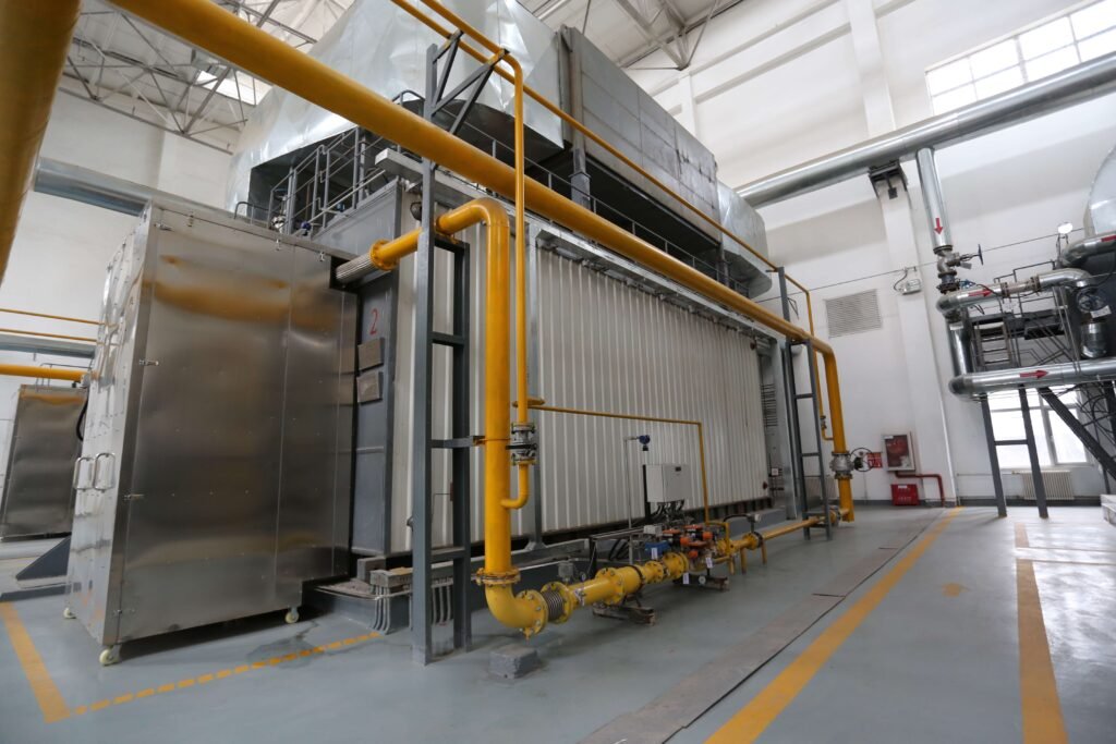
Industrial gas-fired boilers are widely adopted in manufacturing, processing, and energy sectors for their high thermal efficiency, cleaner combustion, and cost-effectiveness. However, without a clear understanding of the key components, businesses may face challenges such as incomplete combustion, system failures, and inefficient fuel usage. These issues can lead to higher operating costs and non-compliance with emission standards. Knowing the core components is essential for reliable operation, safety, and maximum efficiency.

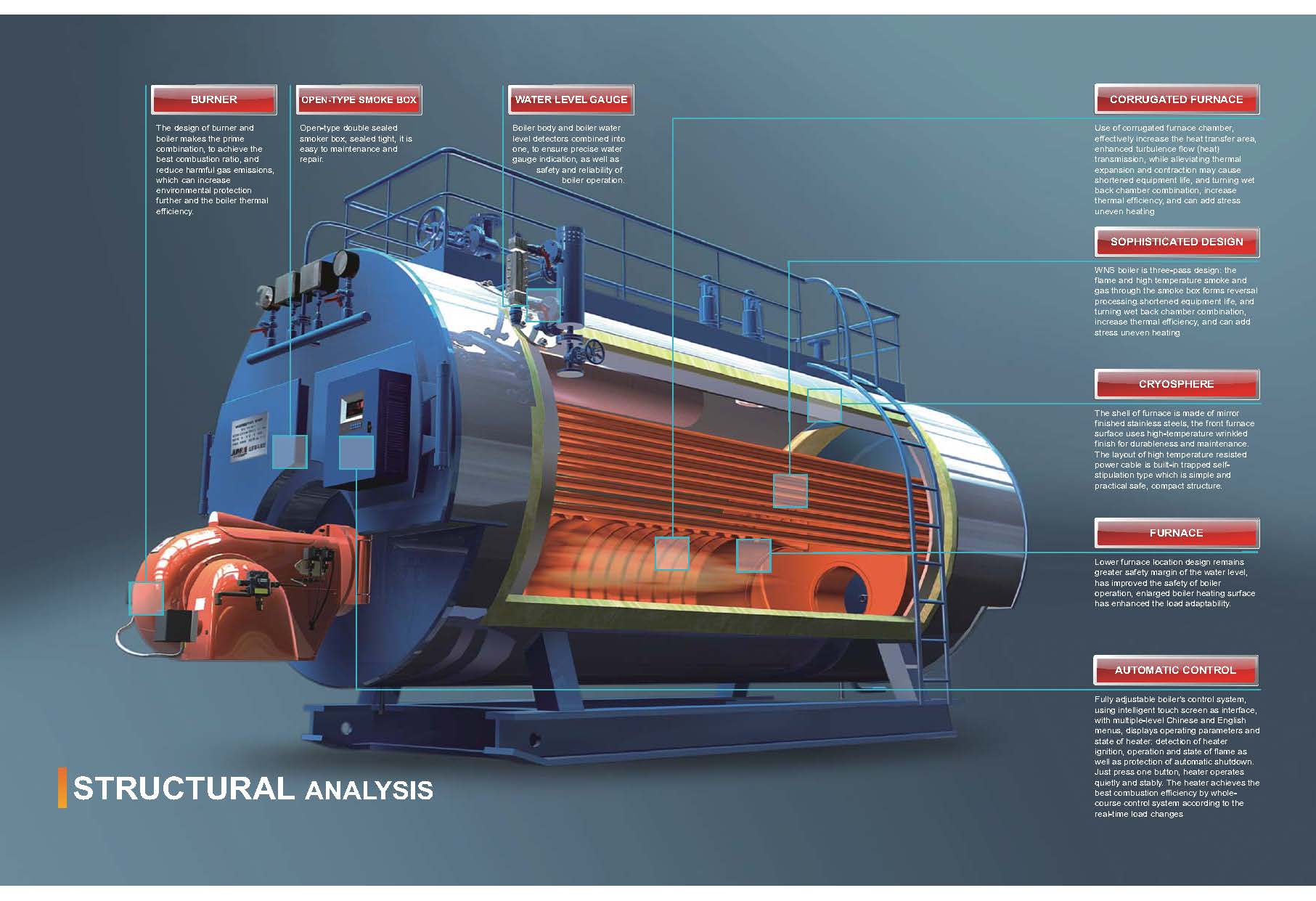
The key components of an industrial gas-fired boiler include the gas burner, combustion chamber, heat exchanger, fuel supply system, air and flue gas handling system, and control system. Each part is vital in achieving efficient gas combustion, optimal heat transfer, and emission control. Advanced gas-fired boilers are equipped with sophisticated monitoring and automation systems to ensure safe and efficient operation.

Understanding how these components function individually and as a system is essential for ensuring reliable performance, energy savings, and long-term operational success.

What Is the Function of the Gas Burner in an Industrial Gas-Fired Boiler?

In any industrial gas-fired boiler, one of the most critical elements for efficient and stable performance is the gas burner. If the burner malfunctions or is poorly designed, it can lead to incomplete combustion, excessive fuel consumption, emissions violations, and even dangerous explosions. For operators, engineers, and facility managers, understanding the true role and function of the gas burner is essential to ensuring optimal boiler operation, energy efficiency, and compliance with environmental standards.

The gas burner in an industrial gas-fired boiler is responsible for mixing the fuel gas with combustion air in precise proportions and igniting the mixture to produce a stable, controlled flame inside the combustion chamber. This process initiates the transfer of heat energy to the water or steam system, ensuring efficient fuel use, complete combustion, minimal emissions, and safe boiler operation.

To truly appreciate the function and impact of a gas burner, one must look beyond its ignition role. This article explains how it supports thermal efficiency, reduces environmental risks, and integrates with automation for advanced control.

How the Gas Burner Works in an Industrial Boiler

The gas burner acts as the core ignition and combustion interface between the boiler system and the fuel source. It operates in several coordinated stages:

1. Fuel-Air Mixing

The gas burner mixes fuel gas (natural gas, LPG, biogas, etc.) with fresh combustion air in a precise stoichiometric ratio. This ratio is critical for efficient combustion—too much air causes heat loss, and too little leads to incomplete burning and carbon monoxide formation.

  • Primary Air Supply: Pre-mixes with gas before ignition.

  • Secondary Air Supply: Supports full combustion during flame propagation.

ParameterTarget ValueImpact
Air-Fuel Ratio10:1 to 12:1Optimized for complete combustion
Excess Air10–20%Prevents CO and unburnt fuel
Flame Temperature1,000–1,900°CDetermines boiler efficiency

2. Ignition Sequence

Using a pilot burner or electric igniter, the gas-air mixture is ignited at the burner nozzle tip. Once a stable flame is detected by flame sensors, the system enters a continuous firing mode.

  • Spark Ignition or Pilot Flame: Starts combustion.

  • Flame Detection Devices: Ensure ignition success and monitor safety.

3. Flame Stabilization and Shaping

Burners are designed to maintain flame stability by managing swirl patterns and flame geometry. Flame shaping is essential to ensure:

  • Complete combustion inside the chamber

  • Prevention of flashback or flame blowout

  • Uniform heat distribution for maximum transfer

Burners can be mono-block (compact, integrated with controls) or duo-block (separate fan and burner unit for larger capacities).


 Types of Industrial Gas Burners

Gas burners vary based on operating principles and system compatibility:

Burner TypeDescriptionTypical Use
Pre-mix BurnerAir and gas are mixed before combustionLow-NOx applications
Surface BurnerFlame propagates across porous materialSpace-constrained systems
Nozzle-mix BurnerAir and gas mixed at the burner tipHigh-turbulence boilers
Modulating BurnerAdjusts flame output to match demandEnergy-efficient boilers

Key Functions and Contributions of the Gas Burner

🔹 Efficient Heat Generation

The burner provides high-temperature flame directly within the combustion chamber, ensuring:

  • Rapid heat transfer to water/steam systems

  • Quick startup times and thermal responsiveness

  • High fuel conversion efficiency (>90%)

🔹 Emission Control

Modern burners are equipped with Low-NOx or Ultra-Low-NOx technology that reduces nitrogen oxide formation by controlling flame temperature and mixing rates.

  • FGR (Flue Gas Recirculation): Reduces peak flame temperatures

  • Staged Combustion: Limits oxygen zones to suppress NOx

  • O2 Trim Controls: Maintain optimum combustion in real time

🔹 System Safety and Flame Monitoring

Burners include redundant flame scanners, pressure switches, and gas valves that protect against backfire, flame loss, or gas leakage. A gas burner integrates into safety loops that:

  • Initiate shutdown during unsafe flame conditions

  • Lockout fuel valves when anomalies are detected

  • Prevent re-ignition until systems are cleared and reset


Gas Burner Performance Optimization

To ensure peak burner efficiency and long-term safety, modern systems use smart control systems and tuning tools:

Optimization FeatureFunctionBenefit
O2 Trim ControlAdjusts combustion airImproves fuel efficiency
Burner TuningAdjusts gas valves and nozzlesMaximizes flame stability
Variable-Speed FansModulate air inputReduces energy use
SCADA/PLC IntegrationReal-time monitoringAutomated alerts and adjustments

Burner Maintenance: Keeping It Reliable

Routine checks are vital for sustaining burner performance. Recommended actions include:

  • Cleaning burner nozzles and flame sensors

  • Verifying gas pressure levels and air damper settings

  • Inspecting ignition systems and safety interlocks

  • Tuning burners quarterly for optimal output

How does the combustion chamber affect energy conversion and emissions?

In industrial boiler systems, especially those powered by biomass, gas, oil, or coal, a common performance bottleneck lies in the combustion chamber. If poorly designed or maintained, it results in incomplete combustion, heat losses, excessive fuel consumption, and elevated emissions of pollutants such as CO, NOx, and particulates. To mitigate these risks and ensure optimal thermal performance, understanding the combustion chamber’s role in energy conversion and emissions is essential for operators and engineers aiming for energy efficiency and environmental compliance.

The combustion chamber serves as the core zone where fuel is ignited and burned, converting chemical energy into thermal energy used for steam or hot water generation. Its design directly affects combustion completeness, heat transfer efficiency, and pollutant formation. A well-optimized combustion chamber ensures maximal energy output from fuel while minimizing unburnt residues and emissions by maintaining ideal temperature, turbulence, residence time, and air-fuel mixing.

Professionals aiming to improve boiler performance must look into how the geometry, insulation, and airflow design of the combustion chamber influence both energy efficiency and emission control.

Key Factors Linking Combustion Chamber Design to Energy Conversion

The combustion chamber’s structure and internal environment determine how efficiently chemical energy in the fuel is transformed into usable thermal energy. The key elements influencing this process include:

  • Temperature Distribution: High and uniform temperatures ensure complete combustion and consistent energy yield.

  • Residence Time: The duration fuel stays in the hot zone affects how completely it burns.

  • Turbulence and Mixing: Enhanced mixing of fuel and combustion air increases reaction speed and completeness.

  • Radiative Heat Transfer: A well-insulated chamber with high-emissivity walls promotes radiative heat transfer, enhancing energy conversion.

Table: Optimal Combustion Parameters for Energy Conversion

ParameterIdeal RangeImpact on Energy Conversion
Combustion Temp850–1,400°CEnsures full fuel oxidation and heat yield
Turbulence IntensityHigh (via swirl/nozzles)Promotes rapid and complete combustion
Residence Time1.5–3.0 secondsAvoids unburnt particles, maximizes heat
Chamber Wall Emissivity>0.9Maximizes radiative heat transfer

The combustion chamber must be lined with refractory material capable of withstanding high temperatures and minimizing heat loss to the environment. High-efficiency designs also incorporate multi-stage combustion zones that extend residence time and allow for optimized burnout of volatile gases and char particles.


Combustion Chamber’s Role in Emissions Formation and Reduction

Besides energy conversion, the combustion chamber plays a pivotal role in determining the type and quantity of emissions produced during fuel combustion. Emissions such as nitrogen oxides (NOx), carbon monoxide (CO), unburnt hydrocarbons, and particulate matter can all be directly traced to combustion conditions.

Emission TypeCause of Formation in ChamberMitigation via Chamber Design
NOxHigh peak temperatures (>1,300°C)Staged combustion, flue gas recirculation
COIncomplete combustion, short residenceImprove air-fuel mix, increase residence
ParticulatesUnburned fuel or ash entrainmentAdd secondary combustion zones or filters
VOCsLow-temperature or poor mixing zonesUniform temp field and air staging

Low-emission combustion chambers employ advanced features such as:

  • Air staging (primary and secondary air ports)

  • Fuel staging (progressive fuel introduction)

  • Flue Gas Recirculation (FGR)

  • Oxygen trim systems (real-time air optimization)

These techniques reduce the flame temperature gradient and oxygen concentration during peak combustion, limiting the formation of thermal NOx without sacrificing energy efficiency.


Case Study: Biomass Boiler Combustion Chamber Optimization

A recent case in a wood-pellet-fired boiler plant involved retrofitting the combustion chamber to reduce stack emissions and fuel costs. The changes included:

  • Installation of swirl vanes to enhance turbulence

  • Repositioning of secondary air inlets

  • Replacement of the refractory lining with a higher emissivity variant

  • Integration of a real-time O2 monitoring system

The results were a 7.8% increase in thermal efficiency, 22% reduction in NOx, and 15% drop in CO emissions within six months of deployment. This illustrates how even modest design enhancements in the combustion chamber significantly influence both output and regulatory compliance.


Design Elements That Maximize Combustion Chamber Efficiency

To achieve high performance from industrial combustion chambers, engineers focus on:

  • Chamber Shape and Geometry: Cylindrical or rectangular with optimized length-to-diameter ratios.

  • Air Injection Technique: Tangential or radial air inlets for enhanced mixing.

  • Flame Stabilization: Swirl burners or flame holders to anchor flame position.

  • Thermal Insulation: High-quality refractory bricks or ceramic fiber boards to retain heat.

Advanced systems use Computational Fluid Dynamics (CFD) modeling during design to simulate flame behavior, temperature distribution, and pollutant formation inside the combustion zone. This helps predict real-world performance and reduce prototyping errors.


Integration with Boiler Control Systems

Modern combustion chambers are no longer passive cavities but active components in the boiler’s control and automation loop. Sensors embedded inside or near the chamber provide data on:

  • Temperature gradients

  • Oxygen levels

  • Flame stability

  • Combustion efficiency

These values feed into PLC or DCS control systems, allowing for real-time adjustment of air/fuel ratio, burner modulation, and safety interlocks. With proper integration, the combustion chamber not only sustains efficiency but also responds dynamically to load changes and environmental conditions.

What role does the heat exchanger play in steam or hot water production?

In industrial boiler systems, insufficient heat transfer leads to poor fuel efficiency, rising energy costs, and inconsistent steam or hot water output. Over time, even minor inefficiencies in the heat exchange process can escalate into major operational bottlenecks—forcing shutdowns, reducing process productivity, or causing thermal imbalance in industrial processes. To overcome these issues, industries depend on the heat exchanger, which plays a pivotal role in converting thermal energy from fuel combustion into usable hot water or steam. In this article, we’ll explore how the heat exchanger works and why it is central to the performance of any steam or hot water system.

The heat exchanger in an industrial boiler is responsible for transferring the thermal energy generated by the combustion of fuel (such as gas, oil, coal, or biomass) into the water or steam system without direct contact between the combustion gases and the working fluid. This component ensures efficient heat absorption, turning cold feedwater into high-temperature hot water or steam. By optimizing the heat transfer surface area, flow dynamics, and thermal conductivity of materials, the heat exchanger significantly boosts the system’s energy efficiency, fuel economy, and thermal reliability.

For professionals managing steam or hot water production, understanding the performance and maintenance of the heat exchanger offers powerful leverage over energy costs, emission targets, and operational uptime. Let’s examine how it works in detail.

How the Heat Exchanger Works Inside an Industrial Boiler

A heat exchanger’s job is to isolate the working fluid (usually water) from the combustion gases while allowing heat to flow efficiently between them. This occurs through thermally conductive materials—typically steel or copper—in one of several standard configurations:

  • Fire-tube design: Combustion gases flow inside tubes surrounded by water. Heat transfers from the gases through the tube walls to the water.

  • Water-tube design: Water circulates inside tubes heated externally by combustion gases—suitable for high-pressure steam applications.

  • Shell-and-tube design: Found in economizers or auxiliary heating applications; one fluid flows through tubes, while another flows around them in the shell.

  • Plate-type heat exchangers: Composed of multiple metal plates with thin flow paths, maximizing heat transfer area—common in compact, high-efficiency boilers.

These exchanger designs vary in complexity and application, but all share a common function: to transfer as much thermal energy as possible with minimal loss.

Common Types of Heat Exchangers and Their Characteristics

Heat Exchanger TypeApplication AreaEfficiency RatingPressure ToleranceMaintenance Needs
Fire-TubeLow-pressure steam/hot waterModerateLow to MediumEasy
Water-TubeHigh-pressure industrial steamHighHighModerate
Shell-and-TubeHeat recovery and economizersMediumMediumModerate
Plate-TypeHot water loops, compact systemsVery HighLowEasy

These configurations allow system designers to balance performance with cost, pressure requirements, and space constraints.

Heat Transfer Efficiency: Technical Performance Insights

Several variables influence how effectively the heat exchanger converts combustion heat into usable thermal output:

  • Temperature differential (ΔT): Greater temperature difference between the flue gas and water results in faster and more effective heat transfer.

  • Thermal conductivity: Materials like copper and aluminum improve heat transfer due to their high thermal conductivity.

  • Surface area: More surface contact between the heat source and the working fluid enables more energy exchange.

  • Flow dynamics: Turbulent flow in pipes or plates can boost heat exchange, although it increases system pressure drop.

Sample Efficiency Curve of Heat Exchanger Performance

Soot Layer Thickness (mm)Heat Transfer Loss (%)
0.00%
0.53%
1.07%
2.012%
3.018%

Even a small buildup of soot or scale can dramatically reduce efficiency, which is why regular cleaning and inspection are critical.

Integration in Steam vs. Hot Water Systems

The role of the heat exchanger differs slightly based on the intended output:

  • Steam Boilers: The exchanger must elevate water temperature beyond 100°C, boiling it under pressure into saturated or superheated steam. This steam is then used in turbines, sterilization, heating, or drying applications.

  • Hot Water Boilers: The exchanger heats water to specific temperature thresholds (usually between 60°C–90°C) for use in heating systems, industrial washing, or hydronic processes.

Each application demands different materials, flow velocities, and heat retention strategies.

Secondary Heat Recovery via Economizers and Condensers

To maximize thermal utilization, modern systems often use a secondary heat exchanger—called an economizer—to extract additional energy from flue gases:

  • Economizers preheat incoming feedwater using flue gas residual heat.

  • Condensing heat exchangers recover latent heat from flue gases by condensing water vapor, increasing overall efficiency above 90%.

This two-stage process minimizes energy loss, reduces fuel consumption, and supports compliance with emission regulations.

Key Technical Benefits of Well-Designed Heat Exchangers

  • Improved fuel-to-steam conversion ratio

  • Enhanced thermal stability across load variations

  • Minimized thermal loss to the environment

  • Reduced scaling and fouling risk with proper materials

  • Support for higher system pressure and temperature

Maintenance Recommendations for Optimal Performance

To maintain top-tier performance, heat exchangers require:

  • Regular internal inspection and tube cleaning

  • Monitoring for pressure drop or temperature anomalies

  • Use of descaling agents to remove mineral buildup

  • Thermal imaging for detecting hot spots or blockages

A preventive maintenance schedule not only extends the life of the heat exchanger but also ensures uninterrupted heat output.

In conclusion, the heat exchanger is more than just a passive component—it’s the heart of thermal energy conversion in industrial boiler systems. By ensuring efficient, consistent, and safe heat transfer, it enables industries to produce steam and hot water at scale, with precision and economy. For any boiler operator or plant engineer, investing in heat exchanger performance is a direct investment in reliability, efficiency, and regulatory compliance.

How does the fuel (gas) supply system ensure consistent and safe operaton?

Gas-fired industrial boilers rely on a continuous and stable fuel supply to maintain efficient heat production and safe operation. If the fuel (gas) supply system fails to deliver gas at the correct pressure or composition, it can result in flame instability, incomplete combustion, equipment damage, or even hazardous explosions. These risks underline the importance of a robust and well-regulated fuel gas supply infrastructure that includes multiple safety layers, pressure controls, and monitoring systems. In this article, we’ll explore how modern fuel gas systems are engineered to ensure both reliability and safety in industrial boiler environments.

The fuel gas supply system ensures consistent and safe operation in an industrial boiler by using a series of pressure regulators, gas filters, safety shut-off valves, control valves, and monitoring sensors to deliver the correct volume of gas at a stable pressure and composition. It protects the burner from pressure fluctuations, contamination, or gas leakage, while maintaining precise control over the fuel-air ratio required for efficient and low-emission combustion. Integrated safety interlocks and alarms enable automatic shutdown in case of abnormalities, thereby preventing operational hazards and ensuring compliance with industrial safety standards.

Understanding how each part of the gas supply system works can help plant engineers and technicians better maintain system integrity, reduce downtime, and comply with increasingly strict emissions and safety codes.

Key Components of the Fuel Gas Supply System

The gas supply system feeding an industrial boiler typically includes the following major components:

ComponentFunction
Gas Pressure RegulatorEnsures gas is supplied at optimal burner pressure
Safety Shut-Off Valve (SSOV)Automatically shuts gas flow in emergencies
Gas Filter/StrainerRemoves particles and impurities from incoming gas
Control ValveModulates gas flow according to demand
Gas Flow MeterMeasures gas consumption for performance tracking
Gas Leak DetectorDetects and alarms any gas leaks in the supply system
Pressure Relief ValveReleases excess gas to avoid over-pressurization
Flame Safeguard ControllerMonitors ignition and flame stability
Low/High Gas Pressure SwitchesTriggers alarms or shutdown if pressure is outside safe range

These components work in a coordinated loop to protect the system while ensuring efficient delivery of fuel to the combustion chamber.

How the System Ensures Consistency

1. Pressure Regulation

The gas entering the plant from an external supplier (e.g., utility pipeline or storage tank) is often at high pressure. A pressure regulator reduces this to a burner-suitable range (typically 20–300 mbar for low-pressure systems). Maintaining consistent pressure is crucial because fluctuations can affect flame characteristics and combustion efficiency.

2. Flow Modulation

The control valve adjusts fuel flow based on boiler load, which varies according to steam or hot water demand. Modulating gas flow ensures consistent combustion and prevents over-firing or under-firing, which could damage equipment or reduce efficiency.

3. Contaminant Removal

Gas filters or strainers trap dust, rust, or oil residues before they reach sensitive components like burners or flow meters. Clean gas promotes stable flame quality and reduces maintenance needs.

4. Redundancy and Monitoring

Modern systems often feature dual regulators, dual shut-off valves, and independent gas trains for backup. Sensors monitor parameters like gas pressure, flow, and temperature, with digital displays feeding into SCADA or DCS platforms for real-time diagnostics.

How the System Ensures Safety

Safety is built into every layer of the gas supply system. Here’s how each mechanism contributes:

Safety FeaturePurpose
Double Shut-Off Valves (SSOV)Stops gas flow in case of emergency or burner failure
Low/High-Pressure SwitchesDetects abnormal pressure and trips system
Gas Leak Detection AlarmsTriggers automatic shutdown if leakage is detected
Flame Supervision (UV or IR)Confirms flame presence; shuts system if flame is lost unexpectedly
Manual Reset MechanismRequires manual intervention to restart after shutdown

These interlocks ensure that in the event of gas supply failure, valve malfunction, or burner issues, the system shuts down immediately to prevent accidents.

Real-World Application: Gas Flow Diagram

Below is a simplified schematic representing a typical industrial boiler gas supply system.

Natural Gas Source → Gas Filter → Pressure Regulator → Control Valve
→ Safety Shut-off Valves (1 & 2) → Flow Meter → Burner

Additional branches might include bypass lines, gas heaters (for LPG systems), or mixing manifolds for dual-fuel capability.

Monitoring and Smart Control Integration

Industrial gas supply systems are increasingly integrated with smart control platforms. These systems provide:

  • Real-time data on pressure, flow, and gas quality

  • Predictive maintenance alerts when filters or valves show signs of wear

  • Integration with burner management systems (BMS) to optimize fuel-air ratio

  • Remote diagnostics for centralized boiler operation

Such capabilities improve both safety response and efficiency monitoring, particularly in multi-boiler installations or large-scale energy plants.

Benefits of a Well-Designed Fuel Gas Supply System

  • Stable combustion: Consistent gas pressure and flow produce optimal flame profiles

  • Energy efficiency: Proper modulation prevents waste and supports low-NOx combustion

  • Longer equipment life: Clean and controlled fuel supply reduces burner wear

  • Regulatory compliance: Safety and emission standards are easier to meet

  • Operational uptime: Redundancy and smart alerts reduce the risk of unscheduled shutdowns

Maintenance Tips for Reliability and Safety

  • Regularly inspect and clean gas filters and strainers

  • Test pressure switches and SSOVs for correct response times

  • Check for gas leakage using calibrated detectors

  • Validate control valve calibration to maintain modulation accuracy

  • Periodically test flame supervision systems

A robust preventive maintenance strategy is the backbone of gas boiler safety and performance.

In summary, the fuel gas supply system is not just a passive pipeline—it’s a dynamic, safety-critical infrastructure that directly impacts the operational integrity and regulatory compliance of industrial boilers. Through precise control, real-time monitoring, and multiple safety redundancies, it ensures reliable fuel delivery, stable combustion, and secure plant operation under a wide range of operating conditions.

What is the importance of the air and flue gas handling system?

In an industrial boiler, efficient combustion and regulatory emissions control are impossible without a well-designed air and flue gas handling system. If air delivery is inconsistent or exhaust gases are not properly treated, the combustion process becomes unstable, fuel consumption increases, and pollutants exceed permissible limits—posing environmental, operational, and safety risks. To prevent these issues, industrial boilers integrate sophisticated systems to manage combustion air intake and flue gas outflow. This article explores the critical role these systems play in maintaining energy efficiency, emission compliance, and system reliability in boiler operations.

The air and flue gas handling system in an industrial boiler ensures proper combustion by delivering the correct volume of air, removing combustion by-products, recovering heat, and controlling pollutant emissions. Primary and secondary air fans regulate airflow for optimal fuel-air mixing, while induced draft (ID) fans and economizers manage exhaust flow and energy recovery. This integrated system guarantees efficient fuel burn, reduces excess air losses, supports heat recovery, and ensures emissions meet environmental regulations.

Understanding the strategic role and technical components of air and flue gas systems is essential for plant managers, energy engineers, and boiler operators aiming to optimize performance and environmental compliance.

Key Functions of the Air and Flue Gas Handling System

FunctionDescription
Air Supply for CombustionDelivers controlled air volume to support stable and complete combustion
Flue Gas RemovalExtracts combustion gases and expels them safely through the stack
Heat RecoveryRecovers residual heat from flue gases using economizers or air preheaters
Emission ControlFilters particulates, NOx, SOx, and other pollutants from flue gases
Pressure Balance and Draft ControlMaintains stable pressure and draft conditions within the boiler

The system ensures the right air-fuel ratio, thermal efficiency, and emissions output across all operational conditions.

Major Components and Their Roles

ComponentFunction
Forced Draft (FD) FanSupplies air to the burner; regulates combustion air volume
Primary Air FanDelivers air to the base of the furnace for drying and transporting fuel
Secondary Air FanEnhances turbulence and air-fuel mixing at the burner level
Induced Draft (ID) FanDraws flue gases from the furnace and pushes them to the stack
EconomizerRecovers heat from exhaust gases to preheat feedwater
Air Preheater (APH)Recovers flue gas heat to preheat combustion air
Flue Gas DuctsChannels flue gases between furnace, economizer, filters, and stack
Stack (Chimney)Safely releases treated flue gases into the atmosphere
Dampers & VFDsModulate flow rates and pressures for air and flue gas

These components form a continuous loop that enables optimal combustion and exhaust management.

Combustion Air System: Ensuring Stable Flame and Efficiency

The air system is responsible for delivering sufficient oxygen to combust the fuel efficiently. Combustion requires three air classifications:

  1. Primary Air: Supports fuel drying and helps transport pulverized coal or biomass into the furnace.

  2. Secondary Air: Injected at the burner zone for complete combustion and flame shaping.

  3. Tertiary Air (optional): Enhances turbulence and helps reduce NOx emissions in advanced systems.

Key operational targets:

  • Maintain proper air-fuel ratio (stoichiometric or slightly excess)

  • Avoid oxygen deficiency (leads to incomplete combustion and CO formation)

  • Avoid excess air (leads to heat losses and lower efficiency)

A combination of dampers, sensors, and Variable Frequency Drives (VFDs) regulate airflow dynamically based on load demand and combustion quality feedback.

Flue Gas Handling System: Extracting, Treating, and Recovering

Flue gases—composed of CO₂, H₂O, N₂, O₂, NOx, SOx, and particulates—are managed through:

  • Induced Draft Fan (ID Fan): Maintains furnace vacuum by drawing out combustion gases.

  • Flue Ducts and Expansion Joints: Direct gases safely to treatment and recovery units.

  • Economizer: Transfers residual flue gas heat to incoming feedwater, reducing fuel demand.

  • Air Preheater: Heats incoming combustion air using exhaust gas heat, improving thermal efficiency.

  • Emission Control Units: Includes cyclones, bag filters, electrostatic precipitators (ESP), DeNOx/DeSOx scrubbers.

Stack emissions are monitored via Continuous Emissions Monitoring Systems (CEMS) to ensure regulatory compliance.

Energy Efficiency Through Heat Recovery

Flue gases typically exit furnaces at 200–400°C. Instead of wasting this thermal energy:

  • Economizers recover heat to raise feedwater temperature (e.g., from 60°C to 120°C), reducing energy required in the boiler drum.

  • Air Preheaters boost the temperature of incoming combustion air (e.g., from ambient 30°C to 150°C), enhancing combustion kinetics.

Heat Recovery UnitFeedwater Temperature GainEfficiency GainFuel Savings
Economizer+50–70°C3–5%Significant
Air Preheater+80–100°C2–4%Moderate

This reduces overall fuel consumption and improves thermal performance, particularly in coal, biomass, or oil-fired boilers.

Emissions Control and Compliance

Flue gas systems are critical in environmental compliance by reducing:

  • Particulate Matter (PM) using cyclones, baghouses, or ESPs

  • Nitrogen Oxides (NOx) via staged combustion, Low-NOx burners, or Selective Catalytic Reduction (SCR)

  • Sulfur Oxides (SOx) through limestone scrubbers or flue gas desulfurization (FGD)

  • Carbon Monoxide (CO) by ensuring complete combustion via optimized air delivery

PollutantPrimary SourceControl TechnologyReduction Efficiency
PMUnburnt ash/residueCyclone, Bag Filter, ESP90–99.9%
NOxHigh temp combustionLow-NOx Burners, SCR, staged air60–95%
SOxSulfur in fuelWet/Dry Scrubbers, FGD80–98%
COIncomplete combustionBurner tuning, oxygen control>99% (with tuning)

Integration with Boiler Control Systems

The entire air and flue gas handling system is integrated with the Boiler Management System (BMS) and Distributed Control System (DCS) for:

  • Automated startup/shutdown sequencing

  • Dynamic load adjustment

  • Alarm generation for airflow/flue gas faults

  • Air-fuel ratio optimization through real-time feedback

Smart sensors and actuators enable real-time adjustments, reducing operator workload and improving responsiveness to load variations or process changes.

Why It Matters for Plant Efficiency and Compliance

A properly designed and maintained air and flue gas handling system provides several critical benefits:

  • Improved fuel efficiency (2–10% depending on recovery strategy)

  • Reduced maintenance by limiting soot and unburnt residues

  • Enhanced combustion stability and flame reliability

  • Lower emissions meeting regulatory targets

  • Operational safety with managed furnace pressure and combustion atmosphere

In short, the air and flue gas handling system is the circulatory and respiratory system of the boiler—it ensures that fuel is burned completely, waste is removed safely, energy is recovered, and emissions are controlled. It’s not just a support system but a core pillar of modern boiler operation strategy.

How do modern control systems enhance boiler performance and safety?

Industrial boilers are the heart of many manufacturing and energy systems, and their performance and safety are crucial to a facility’s efficiency, productivity, and regulatory compliance. However, managing the complex variables involved in boiler operations—like fuel flow, air-to-fuel ratios, pressure, temperature, and emissions—can be challenging without automation. Manual operation leads to human error, energy waste, potential safety incidents, and increased maintenance. Modern control systems eliminate these inefficiencies by delivering precise automation, real-time monitoring, fault detection, and intelligent process optimization. In this article, we explore how these systems revolutionize boiler operations by enhancing both performance and safety.

Modern control systems enhance boiler performance and safety by automating key processes such as fuel-air ratio control, temperature regulation, pressure balance, feedwater management, and alarm handling. These systems use Programmable Logic Controllers (PLCs), Distributed Control Systems (DCS), sensors, actuators, and Human-Machine Interfaces (HMIs) to continuously monitor and optimize operations. This integration leads to improved thermal efficiency, reduced emissions, predictive maintenance, faster troubleshooting, and superior compliance with safety protocols.

Understanding the structure and function of modern boiler control systems is essential for plant managers, engineers, and operators looking to maximize operational uptime, reduce energy costs, and improve workplace safety.

Key Functional Components of a Modern Boiler Control System

ComponentRole
Programmable Logic Controller (PLC)Executes control logic, sequences, safety interlocks
Distributed Control System (DCS)Coordinates control loops across boiler subsystems for stability
Human-Machine Interface (HMI)Provides user dashboard for real-time monitoring and control
Sensors and TransmittersDetect temperature, pressure, flow, and oxygen levels
Actuators and Control ValvesAdjust fuel flow, air dampers, feedwater, steam valves
Safety Interlock SystemsShuts down boiler during unsafe conditions (low water, high pressure)
Alarm and Event Management ModuleNotifies operators of deviations or equipment faults

Each component is integrated into a centralized or distributed control environment, ensuring fast response, precision tuning, and real-time diagnostics.

Core Functions of Boiler Control Systems

  1. Combustion Management System (CMS)

    • Controls the air-fuel ratio for optimal combustion.

    • Uses feedback from oxygen sensors and temperature probes.

    • Minimizes excess air, preventing heat losses and NOx formation.

  2. Feedwater Control System

    • Maintains drum level via three-element control: feedwater flow, steam flow, and drum level.

    • Prevents low water conditions (a major safety hazard).

    • Ensures stable steam output for process requirements.

  3. Drum Pressure and Steam Temperature Control

    • Regulates burner output and fuel valve positioning.

    • Adjusts desuperheater sprays or attemperators for temperature regulation.

    • Maintains steam within tight pressure bands to avoid equipment stress.

  4. Purge and Startup Sequencing

    • Automates safe boiler startup with furnace purging and ignition controls.

    • Ensures proper fan speeds, valve positions, and flame detection.

    • Reduces operator dependency during critical transitions.

  5. Alarm, Safety, and Trip Logic

    • Detects unsafe conditions (e.g., high pressure, flame failure).

    • Initiates automatic shutdown procedures.

    • Logs alarms and sequences for diagnostics.

  6. Emissions Monitoring and Reporting

    • Tracks NOx, CO, SO₂, and particulate levels using Continuous Emissions Monitoring Systems (CEMS).

    • Adjusts combustion parameters for compliance.

Performance Benefits of Modern Boiler Controls

Performance AreaTraditional BoilersModern Control Systems
Fuel EfficiencyManual tuning, higher fuel lossAuto-optimization, better fuel economy
Steam Pressure StabilityFluctuations, risk of trippingTight regulation, high reliability
Oxygen Trim ControlAbsent or delayed responseReal-time excess O₂ adjustment
Load FollowingManual ramp-up/downSmooth load transitions
Heat RateVariableConsistent and lower heat rate

Modern control algorithms allow adaptive learning from load patterns and equipment behavior, further improving outcomes over time.

Safety Enhancements from Integrated Control

Modern systems not only optimize performance but also significantly boost safety:

  • Redundant logic in critical paths ensures safety interlocks always trigger on faults.

  • Flame scanners detect flame presence and initiate immediate shutdown on failure.

  • High-temperature cutoffs and pressure relief valve monitoring prevent overpressure or overheating.

  • Fail-safe valve positions and power redundancy protect the system during electrical outages.

Safety FeatureFunction
Burner Management System (BMS)Manages ignition, flame supervision, purge cycles
Safety Instrumented System (SIS)Independently verifies critical limits and executes emergency shutdown
Emergency Shutdown (ESD) LogicTrips boiler upon any breach of safe operational limits
Historical Event RecordingSupports investigation and root-cause analysis of faults and incidents

These layers of safety help meet regulatory codes such as NFPA 85 (Boiler and Combustion Systems Hazards Code) and IEC 61511 (SIS for Process Industries).

Advanced Features: Digital Twin and Predictive Maintenance

Some modern control systems include:

  • Digital Twins: Real-time virtual models of boiler operations for simulation and diagnostics.

  • Predictive Maintenance Analytics: Uses vibration, temperature, and operational data to forecast equipment failures.

  • Remote Monitoring: Enables 24/7 off-site access for specialists via secure networks.

These capabilities reduce unplanned downtime, extend equipment life, and lower total cost of ownership (TCO).

FeatureValue Addition
Digital Twin ModelingScenario simulation, performance optimization
Predictive MaintenanceCondition-based servicing, reduced breakdowns
Remote Access and Cloud SyncGlobal support, cross-plant performance comparison
AI/ML IntegrationAnomaly detection, combustion tuning, efficiency alerts

Integration with SCADA and Industrial IoT Platforms

Modern control systems are designed to integrate with Supervisory Control and Data Acquisition (SCADA) systems and Industrial Internet of Things (IIoT) platforms for:

  • Centralized monitoring of multiple boilers or plant units

  • Aggregated data visualization and reporting

  • Real-time energy consumption tracking

  • Environmental performance audits

This connectivity creates a digital ecosystem where operators can make data-driven decisions for efficiency, sustainability, and safety.

Real-World Impact and Industry Examples

In a pulp and paper plant in Finland, implementing a modern boiler control system led to:

  • 6% reduction in fuel consumption

  • 20% drop in unplanned downtime

  • Full compliance with EU industrial emissions directives

Similarly, a steel mill in India improved steam pressure stability from ±4 bar to ±0.8 bar, improving product consistency and reducing material rejection.

Industrial segments where control system benefits are particularly impactful include:

  • Chemical and petrochemical refineries

  • Power generation and cogeneration plants

  • Food processing and breweries

  • Pharmaceutical manufacturing

  • Textile dyeing and finishing

These industries often operate 24/7 and require precision steam control and fail-proof safety.

Final Thoughts

Modern boiler control systems are no longer optional add-ons—they are foundational to any high-performance industrial steam or thermal energy system. By delivering automation, precision, and predictive intelligence, these systems unlock significant improvements in fuel efficiency, emission reduction, equipment longevity, and plant safety. For industrial operators facing rising energy costs and tighter environmental regulations, investing in intelligent control systems is a strategic move toward operational excellence.


🔍 Conclusion

Understanding the key components of an industrial gas-fired boiler is crucial for achieving maximum efficiency, safe operation, and environmental compliance. Each element, from the gas burner to the control system, contributes to the boiler’s ability to deliver consistent and clean thermal energy. With proper knowledge and system optimization, industries can reduce fuel costs, enhance uptime, and extend the equipment’s lifespan.

📞 Contact Us

💡 Need expert insight on industrial gas-fired boilers? Whether you’re planning a new installation or upgrading your current system, our team offers customized solutions for efficiency, safety, and performance.

🔹 Contact us today to enhance your industrial gas boiler system! 🔧🔥

Wade Zhang

CEO of Taishan Group Taian Boao International Trade Co., Ltd. 30 years experience in Global industrial boiler market,  Over 300 boiler projects experience, including 21+ EPC projects. Projects span 30+ countries & regions, involving industries such as nuclear power, energy & electricity, municipal heating, mining, textiles, tires etc.

What Are the Key Components of an Industrial Gas-Fired Boiler? Read More »
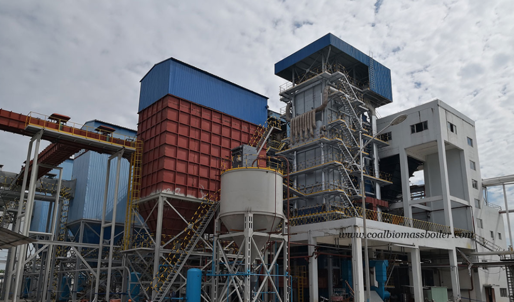
What Are the Core Components of an Industrial Oil-Fired Boiler?

What Are the Core Components of an Industrial Oil-Fired Boiler?

Industrial oil-fired boilers play a vital role in various industries, providing high-efficiency steam and hot water for manufacturing, processing, and power generation. However, inefficiencies, high fuel costs, and maintenance issues can arise if businesses do not fully understand the critical components of these systems. A thorough knowledge of their core parts helps in optimizing performance, reducing fuel consumption, and ensuring regulatory compliance.

The core components of an industrial oil-fired boiler include the burner, combustion chamber, heat exchanger, fuel supply system, exhaust system, and control unit. Each component is essential for ensuring efficient fuel combustion, effective heat transfer, and minimal emissions. Modern oil-fired boilers integrate advanced combustion technologies to improve energy efficiency, enhance safety, and meet environmental regulations.

To ensure optimal efficiency, cost-effectiveness, and longevity, industries must understand how each of these components functions and interacts. Below, we explore the essential parts of an industrial oil-fired boiler in detail.

What Is the Function of the Burner in an Industrial Oil-Fired Boiler?

Industrial oil-fired boilers rely on burners as a critical component for efficient fuel combustion. Without a properly functioning burner, the boiler’s efficiency drops, fuel consumption increases, and emissions rise, leading to higher operational costs and environmental concerns.

The burner in an industrial oil-fired boiler is responsible for atomizing fuel oil, mixing it with air, and igniting the mixture to create a controlled flame for heat generation. This process ensures efficient combustion, optimal heat transfer, and reduced emissions, enhancing boiler performance and fuel efficiency.

By integrating advanced burner designs, automated control systems, and precise fuel-air regulation, modern oil-fired boilers achieve higher efficiency, lower fuel waste, and improved emissions compliance.


1. Key Functions of an Oil-Fired Boiler Burner

Burners in industrial oil-fired boilers play a crucial role in energy conversion.

A. Fuel Atomization and Injection

✅ Breaks down liquid fuel oil into fine droplets for better mixing with air.
✅ Ensures complete combustion and minimizes unburned fuel losses.

B. Air-Fuel Mixture Control

✅ Precisely regulates air and fuel proportions for optimal combustion efficiency.
✅ Prevents excess air, which reduces efficiency, and incomplete combustion, which increases emissions.

C. Stable and Controlled Flame Generation

✅ Produces a stable flame for consistent heat transfer.
✅ Maintains steady steam production in industrial processes.

FunctionPurposeEfficiency Impact
Fuel AtomizationCreates fine fuel dropletsImproves combustion quality
Air-Fuel ControlRegulates mixture ratioReduces energy loss
Flame StabilizationEnsures steady heat outputPrevents temperature fluctuations

2. Types of Burners Used in Oil-Fired Boilers

Modern industrial oil-fired boilers use different burner designs to enhance performance.

A. Pressure Jet Burners

✅ Uses high-pressure fuel injection to atomize oil.
✅ Common in large industrial applications due to high efficiency.

B. Rotary Cup Burners

✅ Uses a rotating cup to break fuel into fine mist.
✅ Suitable for low-viscosity fuels and offers stable combustion.

C. Steam or Air-Assisted Burners

✅ Uses compressed air or steam to atomize heavy oils.
✅ Ideal for burning residual fuels with higher viscosity.

Burner TypeFuel CompatibilityEfficiency
Pressure JetLight & medium oilsHigh
Rotary CupLight oilsMedium
Steam/Air-AssistedHeavy & residual oilsHigh

3. How Modern Burners Improve Efficiency and Reduce Emissions

A. Low NOx Burner Technology

✅ Reduces nitrogen oxide (NOx) emissions by controlling flame temperature.
✅ Uses staged combustion and flue gas recirculation to lower NOx levels.

B. Oxygen Trim Control

✅ Continuously monitors oxygen levels in flue gases.
✅ Adjusts air supply to prevent excess air and maximize efficiency.

C. Advanced Flame Monitoring & Control

✅ Uses infrared and ultraviolet sensors to detect flame stability.
✅ Prevents fuel wastage and unburned hydrocarbons.

TechnologyEfficiency GainEmissions Reduction
Low NOx Burner5-10%Reduces NOx emissions
Oxygen Trim Control2-6%Minimizes excess air losses
Flame Monitoring3-7%Prevents fuel wastage

4. Challenges in Burner Operation and Maintenance

Despite their efficiency, burners require regular maintenance to prevent performance issues.

A. Fuel Quality Issues

Impurities in oil can clog nozzles and reduce combustion efficiency.
Solution: Use proper filtration systems and preheat heavy fuels.

B. Burner Fouling and Deposits

Soot and carbon buildup reduce flame efficiency.
Solution: Regular burner cleaning and airflow adjustments.

C. Wear and Tear of Components

Nozzle erosion and fan degradation impact performance.
Solution: Routine inspection and replacement of worn-out parts.

ChallengeSolutionImpact on Efficiency
Fuel ImpuritiesFiltration & preheatingPrevents nozzle clogging
Burner FoulingRegular cleaningMaintains steady combustion
Component WearTimely replacementPrevents unexpected failures

5. Future Trends in Oil Burner Technology

Burner technology is continuously evolving to meet stricter efficiency and emission standards.

A. AI-Based Burner Optimization

✅ Uses machine learning to predict fuel demand and optimize combustion.
✅ Adjusts burner settings in real time to maximize efficiency.

B. Hybrid Burners (Multi-Fuel Capability)

✅ Designed to switch between oil, gas, and alternative fuels.
✅ Enhances fuel flexibility and reduces dependence on fossil fuels.

C. Ultra-Low Emission Burners

✅ Uses advanced air staging and recirculation techniques.
✅ Minimizes CO2 and NOx emissions, aligning with environmental regulations.

Future TechnologyEfficiency ImpactEnvironmental Benefit
AI Optimization8-12%Reduces fuel wastage
Multi-Fuel Burners5-10%Enhances fuel flexibility
Ultra-Low NOx Burners10-20%Meets stricter emission standards


How Does the Combustion Chamber Contribute to Heat Generation?

The combustion chamber is the core component of an industrial boiler where fuel combustion occurs, generating heat energy for steam production. Its design directly impacts boiler efficiency, fuel consumption, and emission levels. A well-optimized combustion chamber maximizes heat transfer, minimizes fuel wastage, and ensures complete combustion, enhancing overall system performance.

1. Functions of the Combustion Chamber in Heat Generation

The combustion chamber plays a vital role in heat production by facilitating efficient fuel combustion.

A. Fuel-Air Mixing for Complete Combustion

✅ Precisely blends fuel and air to achieve optimal combustion efficiency.
✅ Prevents incomplete combustion, which can lead to heat loss and higher emissions.

B. High-Temperature Heat Transfer

✅ Converts chemical energy from fuel into thermal energy.
✅ Transfers heat to boiler water through radiation and convection, producing high-pressure steam.

C. Flame Stabilization for Consistent Heating

✅ Ensures a steady and controlled flame to maintain uniform heat distribution.
✅ Reduces temperature fluctuations, preventing thermal stress on boiler components.

FunctionPurposeImpact on Heat Generation
Fuel-Air MixingEnsures complete combustionMaximizes energy conversion
Heat TransferTransfers thermal energy to waterGenerates steam efficiently
Flame StabilizationMaintains steady combustionReduces temperature variations

2. Key Components of a Combustion Chamber

A combustion chamber consists of multiple elements designed to enhance heat generation.

A. Burner Assembly

✅ Injects fuel into the chamber in an atomized form for efficient burning.
✅ Regulates the fuel-air ratio for optimal combustion conditions.

B. Refractory Lining

✅ High-temperature insulating material that retains heat within the chamber.
✅ Protects the boiler structure from thermal damage and reduces heat loss.

C. Air and Gas Flow Control

✅ Manages the supply of combustion air to maintain efficiency.
✅ Ensures proper exhaust gas flow to prevent heat buildup and pressure imbalances.

ComponentFunctionBenefit
BurnerFuel injection and mixingEfficient combustion
Refractory LiningInsulation and heat retentionReduces energy loss
Air/Gas FlowControls combustion atmosphereImproves efficiency

3. Factors Affecting Combustion Chamber Efficiency

Several factors influence how effectively a combustion chamber generates heat.

A. Fuel Quality and Atomization

✅ High-quality fuel with low moisture and consistent calorific value burns efficiently.
✅ Proper atomization ensures fine fuel droplets, enhancing the combustion process.

B. Air-Fuel Ratio Control

Precise air regulation prevents excess oxygen (which reduces efficiency) and unburned fuel (which increases waste).
✅ Advanced oxygen sensors and trim systems optimize air input dynamically.

C. Chamber Design and Insulation

✅ A well-designed chamber with optimized flame pathways maximizes heat transfer.
✅ Proper insulation reduces heat dissipation losses, keeping temperatures stable.

FactorEffect on EfficiencyOptimization Strategy
Fuel QualityHigher calorific value = more heatUse refined fuel & preheating
Air-Fuel RatioPrevents incomplete combustionInstall oxygen trim controls
Chamber InsulationMinimizes heat lossUse high-quality refractory materials

4. How Modern Combustion Chambers Enhance Performance

A. Low NOx Combustion Technology

✅ Uses staged combustion and flue gas recirculation to lower nitrogen oxide (NOx) emissions.
✅ Reduces excess air demand, improving heat generation efficiency.

B. High-Efficiency Heat Transfer Designs

✅ Incorporates multi-pass flame paths to maximize radiation and convective heat absorption.
✅ Improves steam production rate with minimal fuel consumption.

C. Smart Combustion Control Systems

✅ Uses AI-driven sensors to adjust fuel injection, air supply, and temperature in real time.
✅ Prevents overheating or inefficient burning, ensuring optimal heat output.

TechnologyEfficiency ImpactOperational Benefit
Low NOx Combustion5-10% increaseReduces emissions
Multi-Pass Heat Transfer8-12% gainMaximizes energy use
AI Combustion Control10-15% gainAdjusts real-time settings

5. Challenges in Combustion Chamber Operation

Despite advancements, some challenges impact combustion chamber performance.

A. Soot and Carbon Deposits

Excess carbon buildup reduces heat transfer efficiency.
Solution: Implement regular cleaning and soot blowers.

B. Thermal Stress and Cracking

Extreme temperature variations cause cracks in the refractory lining.
Solution: Use high-durability refractory materials and gradual heating during startup.

C. Improper Fuel-Air Mixing

Uneven air distribution leads to hot spots and uneven combustion.
Solution: Install advanced burner designs and dynamic air control systems.

IssueImpactSolution
Carbon DepositsLowers heat transferRegular cleaning & soot blowers
Thermal StressCracks refractory wallsUse high-durability materials
Poor Air MixingUneven flame distributionAdvanced burner control

6. Future Innovations in Combustion Chamber Design

A. Ultra-Low Emission Combustion

✅ Uses oxygen-enriched combustion to burn fuel more cleanly and efficiently.
✅ Reduces carbon footprint without sacrificing performance.

B. Hybrid Combustion Systems

✅ Allows switching between fossil fuels and biofuels to enhance sustainability.
✅ Adapts to changing fuel availability and cost variations.

C. AI-Powered Self-Learning Burners

✅ Uses real-time data analytics to adjust air and fuel inputs dynamically.
✅ Prevents combustion inefficiencies and heat losses.

Future TrendEfficiency BenefitEnvironmental Impact
Oxygen-Enriched Combustion10-15% gainLower CO2 emissions
Hybrid Fuel Compatibility8-12% increaseGreater fuel flexibility
AI-Driven Burners12-18% boostMinimizes energy waste


What Role Does the Heat Exchanger Play in Steam and Hot Water Production?

The heat exchanger is a critical component in steam and hot water production, responsible for transferring thermal energy from a heat source to water. It ensures efficient energy utilization, temperature regulation, and system longevity. An optimized heat exchanger enhances boiler efficiency, reduces fuel consumption, and maintains consistent steam or hot water supply.

1. Functions of a Heat Exchanger in Steam and Hot Water Production

The heat exchanger plays a fundamental role in thermal energy conversion within a boiler system.

A. Heat Transfer from Combustion Gases to Water

✅ Extracts thermal energy from hot flue gases generated during fuel combustion.
✅ Transfers this heat to water, converting it into steam or hot water.

B. Temperature Regulation for Process Efficiency

✅ Maintains optimal water temperature levels, preventing overheating or energy loss.
✅ Controls steam pressure to meet industrial process requirements.

C. Energy Conservation and Fuel Efficiency

✅ Maximizes heat absorption, reducing fuel consumption and operational costs.
✅ Enhances thermal efficiency, leading to improved boiler performance.

FunctionPurposeImpact on Steam & Hot Water Production
Heat TransferConverts fuel energy into thermal energyGenerates high-efficiency steam & hot water
Temperature RegulationMaintains stable thermal outputPrevents overheating & improves system control
Energy ConservationReduces heat loss & fuel wastageEnhances fuel economy & performance

2. Types of Heat Exchangers in Steam and Hot Water Systems

There are several types of heat exchangers designed for different industrial applications.

A. Shell-and-Tube Heat Exchangers

✅ Composed of multiple tubes enclosed within a cylindrical shell.
Hot gases flow over the tubes, transferring heat to water inside the tubes.

B. Plate Heat Exchangers

✅ Uses thin metal plates with high surface area for efficient heat exchange.
✅ Suitable for compact systems requiring rapid heat transfer.

C. Fin-Tube Heat Exchangers

✅ Incorporates extended surface fins to enhance heat absorption and transfer.
✅ Common in high-efficiency boiler applications.

Heat Exchanger TypeStructureEfficiencyCommon Application
Shell-and-TubeCylindrical shell with multiple tubesHighLarge-scale steam production
PlateMetal plates with narrow channelsVery HighHot water heating
Fin-TubeTubes with extended fin surfacesModerate-HighHigh-efficiency boilers

3. How the Heat Exchanger Enhances System Efficiency

Several design factors contribute to the effectiveness of a heat exchanger in a steam and hot water system.

A. Optimized Heat Transfer Surface Area

Larger surface areas allow greater heat absorption and faster temperature rise.
✅ Multi-pass designs increase contact time between water and heat source.

B. Efficient Fluid Flow Management

✅ Ensures uniform heat distribution, preventing localized overheating.
✅ Uses baffles and flow control valves to regulate heat transfer.

C. Condensation and Heat Recovery

✅ Captures latent heat from steam condensation, improving efficiency.
✅ Reduces wasted thermal energy, leading to lower fuel consumption.

Efficiency FactorEffect on PerformanceOptimization Strategy
Large Heat Transfer SurfaceIncreases heat absorptionUse finned or plate exchangers
Uniform Fluid FlowPrevents overheating & cold spotsInstall flow regulation systems
Heat RecoveryReduces energy lossIntegrate economizers & condensate recovery

4. Challenges in Heat Exchanger Operation

Despite their advantages, heat exchangers face operational challenges that impact performance.

A. Fouling and Scaling Build-Up

Mineral deposits and soot reduce heat transfer efficiency.
Solution: Regular cleaning and descaling with chemical treatments.

B. Corrosion and Material Degradation

❌ Exposure to high-temperature and corrosive gases weakens components.
Solution: Use corrosion-resistant alloys and protective coatings.

C. Pressure Drop and Flow Restrictions

❌ Accumulated deposits lead to reduced water flow and uneven heating.
Solution: Install automatic blowdown and monitoring systems.

IssueImpact on EfficiencySolution
Fouling & ScalingLowers heat transferRegular cleaning & water treatment
CorrosionWeakens componentsUse high-quality alloys
Flow RestrictionsUneven heatingImplement automatic monitoring

5. Future Advancements in Heat Exchanger Technology

Technological innovations are enhancing heat exchanger performance for steam and hot water production.

A. High-Efficiency Condensing Heat Exchangers

✅ Recaptures waste heat from exhaust gases for additional energy savings.
✅ Increases fuel efficiency by 10-15% compared to conventional designs.

B. Smart Sensor Monitoring for Predictive Maintenance

✅ Uses IoT-based sensors to track temperature, pressure, and fouling rates.
✅ Reduces unplanned shutdowns through real-time diagnostics.

C. Nanotechnology-Coated Heat Exchangers

Nano-coatings reduce fouling and corrosion, extending lifespan.
✅ Improves heat transfer rates by minimizing surface resistance.

InnovationEfficiency ImpactOperational Benefit
Condensing Heat Exchangers10-15% gainReduces fuel consumption
Smart Sensor Monitoring8-12% gainPrevents failures & improves reliability
Nano-Coatings12-18% boostMinimizes fouling & corrosion


How Does the Fuel Supply System Ensure Efficient Operation?

The fuel supply system is a critical component in industrial boilers and power generation systems. It ensures a consistent, controlled, and efficient delivery of fuel to maintain stable combustion, optimize energy output, and minimize waste. By integrating automated handling, precise metering, and real-time monitoring, fuel supply systems maximize operational efficiency, reduce emissions, and enhance cost-effectiveness.

1. Key Functions of the Fuel Supply System

The fuel supply system is responsible for fuel storage, transportation, metering, and regulation to ensure efficient energy generation.

A. Fuel Storage and Handling

✅ Maintains adequate fuel reserves for continuous operation.
✅ Uses sealed tanks or silos to prevent contamination and degradation.

B. Fuel Transportation to the Boiler

✅ Transfers fuel from storage units to combustion chambers via conveyors, pumps, or pipelines.
✅ Utilizes automated fuel feeders for consistent delivery rates.

C. Precise Fuel Metering and Regulation

✅ Ensures the correct amount of fuel is supplied based on system demand.
✅ Prevents fuel overloading or underfeeding, which can affect combustion stability.

D. Safety and Emission Control

✅ Monitors fuel pressure, temperature, and flow rates to avoid system failures.
✅ Incorporates filters, separators, and safety shutoffs to prevent contamination and hazards.

FunctionRole in EfficiencyImpact on Operation
Fuel StorageEnsures fuel availabilityPrevents supply shortages
Fuel TransportDelivers fuel smoothly to burnersAvoids combustion disruptions
Fuel MeteringControls fuel inputOptimizes combustion & minimizes waste
Safety MonitoringDetects leaks & prevents hazardsReduces risks & improves reliability

2. Types of Fuel Supply Systems in Industrial Applications

Different industries use fuel supply systems tailored to specific energy needs.

A. Solid Fuel Supply Systems (Coal, Biomass, Wood Chips)

✅ Uses conveyors, augers, or pneumatic systems to transport fuel.
✅ Includes crushers and feeders for size reduction and controlled feeding.

B. Liquid Fuel Supply Systems (Heavy Oil, Diesel, Kerosene)

✅ Employs pumps, pipelines, and preheaters for efficient oil transport.
✅ Uses fuel filters to remove impurities, ensuring cleaner combustion.

C. Gaseous Fuel Supply Systems (Natural Gas, LPG, Biogas)

✅ Delivers fuel through pressurized pipelines and safety valves.
✅ Incorporates pressure regulators and flow meters for consistent gas flow.

Fuel TypeSupply MethodEfficiency Consideration
Solid FuelsConveyor & auger feedersRequires size control & steady feed
Liquid FuelsPumps & filtersNeeds preheating & impurity removal
Gaseous FuelsPipelines & regulatorsRequires precise pressure control

3. Optimizing Fuel Supply for Maximum Efficiency

To achieve high operational efficiency, fuel supply systems must be optimized for consistent delivery, proper combustion, and minimal waste.

A. Fuel Preprocessing and Conditioning

Coal and biomass are pulverized or dried to improve combustion efficiency.
Heavy oils are preheated to reduce viscosity for smooth flow.
Gas fuels are pressure-regulated for stable burning.

B. Automated Fuel Feeding Systems

✅ Uses smart sensors and real-time monitoring to adjust fuel flow based on demand.
✅ Prevents over-fueling, which causes excessive emissions, and under-fueling, which leads to incomplete combustion.

C. Advanced Control and Monitoring Technologies

SCADA and IoT systems track fuel flow rates, pressure levels, and temperature changes.
✅ AI-based predictive maintenance reduces fuel wastage and prevents unexpected breakdowns.

Optimization MethodImpact on EfficiencyBenefit
Fuel PreprocessingEnhances combustionReduces emissions & fuel consumption
Automated Fuel FeedingAdjusts supply dynamicallyPrevents energy losses
Smart MonitoringDetects inefficienciesPrevents downtime & improves reliability

4. Challenges and Solutions in Fuel Supply Management

Despite technological advancements, fuel supply systems face operational challenges.

A. Fuel Quality Variability

Inconsistent fuel properties can lead to unstable combustion.
Solution: Implement fuel quality monitoring and preprocessing techniques.

B. Supply Disruptions and Shortages

Delivery delays or supply chain issues can halt production.
Solution: Maintain adequate fuel reserves and backup systems.

C. Equipment Wear and Tear

Pipelines, pumps, and conveyors degrade over time, affecting performance.
Solution: Implement regular maintenance and condition monitoring.

IssueImpact on Fuel EfficiencySolution
Fuel VariabilityCauses combustion instabilityUse fuel homogenization techniques
Supply DisruptionsLeads to operational downtimeMaintain backup storage
Equipment WearReduces fuel flow efficiencyConduct preventive maintenance

5. Future Trends in Fuel Supply System Optimization

Advancements in fuel supply technology continue to improve system efficiency.

A. AI-Powered Fuel Flow Optimization

✅ Uses machine learning to predict fuel demand and adjust flow rates automatically.
✅ Reduces fuel waste and energy losses.

B. Integration of Renewable Fuels

✅ Expanding the use of biofuels, hydrogen, and synthetic gases in industrial fuel supply systems.
✅ Decreases dependence on fossil fuels and reduces carbon footprint.

C. Smart Fuel Storage and Management Systems

Automated fuel inventory tracking ensures efficient supply chain management.
✅ Reduces fuel wastage and operational inefficiencies.

InnovationEfficiency ImpactOperational Benefit
AI-Powered Fuel Flow10-15% improvementReduces fuel consumption
Renewable Fuel Integration20-30% emissions reductionEnhances sustainability
Smart Storage Systems12-18% efficiency gainMinimizes supply risks

What Is the Purpose of the Exhaust System in an Oil-Fired Boiler?

An oil-fired boiler’s exhaust system is crucial for removing combustion byproducts, ensuring safe operation, and maintaining regulatory compliance. This system manages flue gases, recovers heat energy, and reduces harmful emissions. Without a properly functioning exhaust system, an oil-fired boiler could experience inefficiency, increased emissions, and safety hazards.

1. Key Functions of the Exhaust System

The exhaust system in an oil-fired boiler serves multiple essential functions to ensure efficiency, safety, and environmental compliance.

A. Safe Removal of Combustion Gases

✅ Channels flue gases, including carbon dioxide (CO₂), nitrogen oxides (NOx), sulfur oxides (SOx), and unburned hydrocarbons, away from the boiler.
✅ Prevents toxic gas buildup, reducing the risk of workplace hazards.

B. Emission Reduction and Pollution Control

✅ Uses filters, scrubbers, and catalytic converters to limit particulate matter, sulfur compounds, and nitrogen oxides.
✅ Meets environmental regulations such as EPA, EU emission standards, and ISO requirements.

C. Heat Recovery for Energy Efficiency

✅ Recovers heat from flue gases using economizers and heat exchangers to improve boiler efficiency.
✅ Reduces fuel consumption by preheating feedwater or air intake.

FunctionRole in Boiler OperationEfficiency Impact
Flue Gas RemovalPrevents toxic buildupEnsures safe combustion
Emission ControlReduces pollutantsMeets regulatory compliance
Heat RecoveryImproves fuel efficiencyLowers operating costs

2. Main Components of an Oil-Fired Boiler Exhaust System

The exhaust system consists of multiple components that work together to ensure efficient and compliant operation.

A. Flue Gas Stack (Chimney)

✅ Directs combustion gases safely into the atmosphere.
✅ Designed for proper height and diameter to optimize gas dispersion and prevent backpressure.

B. Economizer (Heat Recovery Unit)

✅ Captures waste heat from flue gases to preheat boiler feedwater.
✅ Enhances fuel efficiency by 5–10%, reducing operational costs.

C. Air Preheater

✅ Uses flue gas heat to pre-warm combustion air, increasing thermal efficiency.
✅ Improves fuel-to-air mixing, reducing excess fuel consumption.

D. Flue Gas Scrubber and Particulate Filters

✅ Removes SOx, NOx, and particulate matter using chemical reactions and filtration.
✅ Ensures compliance with environmental regulations.

E. Draft Fan (Induced Draft and Forced Draft Fans)

✅ Controls the movement of exhaust gases to maintain proper air-to-fuel ratios.
✅ Prevents flue gas backflow, maintaining consistent pressure.

ComponentFunctionEfficiency Benefit
Flue Gas StackExpels gases into the airPrevents hazardous gas buildup
EconomizerRecovers heatIncreases fuel efficiency by 5-10%
Air PreheaterPreheats combustion airReduces fuel consumption
Scrubber & FiltersRemoves pollutantsImproves air quality & compliance
Draft FanRegulates exhaust flowMaintains combustion stability

3. Importance of Heat Recovery in Exhaust Systems

Recovering heat from flue gases is one of the most effective ways to improve boiler efficiency.

A. How Heat Recovery Works

Economizers transfer flue gas heat to incoming feedwater, reducing energy loss.
Air preheaters increase combustion air temperature, reducing fuel demand.
Condensing heat exchangers extract additional heat by cooling flue gases below the dew point, capturing latent heat.

B. Energy Efficiency Gains

Standard heat recovery increases efficiency by 5–10%.
Advanced condensing economizers boost efficiency by 15–20%, especially in high-moisture fuel combustion.

Heat Recovery MethodEfficiency ImprovementFuel Savings
Economizer5-10%Moderate
Air Preheater5-7%Significant
Condensing Heat Exchanger15-20%High

4. Environmental Compliance and Emission Reduction

Exhaust systems help oil-fired boilers meet strict environmental regulations by controlling air pollutants.

A. Pollutants in Flue Gases

Sulfur oxides (SOx): Formed from sulfur in fuel oil, contributing to acid rain.
Nitrogen oxides (NOx): Produced at high combustion temperatures, leading to smog formation.
Particulate matter (PM): Includes soot, ash, and unburned hydrocarbons.

B. Emission Control Technologies

Scrubbers: Use chemical reactions to remove SOx and NOx.
Electrostatic Precipitators (ESP): Capture fine particulates from exhaust gases.
Selective Catalytic Reduction (SCR): Converts NOx into harmless nitrogen and water vapor.

PollutantSourceControl Method
Sulfur Oxides (SOx)Sulfur in fuel oilWet scrubbers
Nitrogen Oxides (NOx)High combustion tempsSCR system
Particulate Matter (PM)Incomplete combustionESP filters

5. Challenges and Solutions in Exhaust System Management

Despite advanced designs, exhaust systems face operational challenges that must be addressed.

A. Corrosion and Scaling

High-temperature gases and acidic condensation cause metal degradation.
Solution: Use corrosion-resistant materials and install drainage systems for condensation.

B. Backpressure Issues

❌ Improper stack height or fan failure can cause inefficient exhaust flow.
Solution: Use variable-speed draft fans to regulate pressure and airflow.

C. High Operating Costs for Emission Controls

❌ Scrubber systems and filters require maintenance and energy input.
Solution: Implement heat recovery to offset costs and adopt automated monitoring systems.

IssueImpact on EfficiencySolution
CorrosionReduces component lifespanUse corrosion-resistant materials
BackpressureDecreases combustion efficiencyInstall draft fans & adjust stack design
High Emission Control CostsIncreases operational expensesIntegrate heat recovery systems

6. Future Trends in Oil-Fired Boiler Exhaust Systems

Innovations are shaping the future of exhaust system efficiency and sustainability.

A. Smart Exhaust Monitoring Systems

✅ Uses IoT sensors to track emission levels and optimize air-to-fuel ratios in real-time.
✅ Reduces fuel consumption and enhances compliance.

B. Advanced Heat Recovery Systems

✅ Developments in nano-coated heat exchangers improve heat recovery rates.
Supercritical steam technology increases efficiency in industrial plants.

C. Transition to Cleaner Fuels

✅ Adoption of low-sulfur fuel oils and biofuel blends reduces emissions.
✅ Carbon capture and storage (CCS) technologies are emerging as long-term emission control solutions.

InnovationBenefit
Smart Exhaust MonitoringReal-time optimization & lower emissions
Advanced Heat RecoveryIncreased fuel efficiency
Cleaner Fuel TransitionLower environmental impact


How Do Modern Control Systems Enhance Efficiency and Safety in Industrial Boilers?

Industrial boilers are complex systems that require precise control to operate efficiently and safely. Modern control systems leverage automation, real-time monitoring, and advanced sensors to enhance performance, reduce fuel consumption, and minimize risks. Without an intelligent control system, a boiler can suffer from inefficiencies, safety hazards, and excessive emissions, leading to higher operational costs and environmental non-compliance.

1. Key Functions of Modern Boiler Control Systems

Modern control systems provide several critical functions that optimize performance, ensure safety, and comply with regulations.

A. Automation for Efficiency Optimization

Automated Fuel-Air Ratio Control: Adjusts fuel and air supply dynamically for optimal combustion efficiency.
Load Regulation: Adapts boiler operation to real-time demand fluctuations, reducing energy waste.

B. Real-Time Monitoring and Data Analysis

Continuous Temperature and Pressure Monitoring: Ensures stable operations by preventing overheating or pressure drops.
Predictive Maintenance Alerts: Uses AI and IoT to detect potential failures before they occur, reducing downtime.

C. Safety Enhancements and Emergency Shutdown

Automatic Safety Shutdown Mechanisms: Detects abnormal conditions like high pressure or low water levels and shuts down the system to prevent explosions.
Remote Monitoring & Control: Enables real-time adjustments and emergency response through cloud-based interfaces.

FunctionImpact on EfficiencyImpact on Safety
Fuel-Air Ratio ControlReduces fuel wastagePrevents incomplete combustion
Load RegulationAdapts to demandPrevents overheating
Temperature MonitoringOptimizes heat transferAvoids thermal stress damage
Predictive MaintenanceReduces downtimePrevents equipment failure
Emergency ShutdownPrevents explosionsEnsures operator safety

2. Components of a Modern Boiler Control System

Modern control systems integrate multiple components to ensure precise regulation, real-time diagnostics, and automation.

A. Programmable Logic Controller (PLC) & Distributed Control System (DCS)

Automates operations, eliminating manual errors.
Manages fuel input, water levels, and exhaust gas emissions with precision.

B. Smart Sensors and IoT Devices

Measure pressure, temperature, flow rate, and emissions in real-time.
Transmit data to a central control unit for continuous optimization.

C. Human-Machine Interface (HMI) & Remote Monitoring

✅ Allows operators to monitor system performance from a control room or remotely.
✅ Displays real-time alerts and diagnostics to detect anomalies early.

D. Advanced Safety Systems

Failsafe mechanisms prevent hazardous situations like pressure surges or flameouts.
Emergency shutdown protocols stop operations when safety thresholds are exceeded.

ComponentFunctionImpact on Operations
PLC/DCSAutomates controlImproves consistency & efficiency
IoT SensorsMonitors real-time dataEnables predictive maintenance
HMI & Remote ControlProvides real-time alertsReduces manual monitoring workload
Safety SystemsPrevents hazardous conditionsEnhances workplace safety

3. Efficiency Gains from Modern Control Systems

A well-optimized control system reduces energy consumption, minimizes downtime, and improves fuel efficiency.

A. Fuel Efficiency Improvements

Optimized combustion controls reduce excess air and unburned fuel losses.
Heat recovery integration adjusts steam production based on demand.

B. Reduced Downtime and Maintenance Costs

Predictive analytics detect minor faults before they cause failures.
Automated scheduling ensures timely maintenance, preventing costly breakdowns.

C. Energy Savings Through Smart Load Management

✅ Adjusts boiler output based on real-time demand to reduce unnecessary fuel consumption.
✅ Integrates with smart grids to optimize energy use based on peak and off-peak hours.

Efficiency FactorBenefitCost Savings
Combustion OptimizationReduces fuel waste5-15% fuel cost reduction
Predictive MaintenancePrevents failures20-30% lower maintenance costs
Load ManagementMatches demandReduces excess fuel use

4. Safety Enhancements with Smart Boiler Controls

Modern control systems integrate advanced safety features to prevent accidents and ensure operational stability.

A. Automatic Fault Detection and Alarms

Detects leaks, pressure surges, and flame irregularities before they escalate.
Triggers alarms and automated shutdowns to prevent accidents.

B. Redundancy and Backup Systems

Failsafe mechanisms ensure continued operation during sensor malfunctions.
Backup power and redundant controllers prevent system crashes.

C. Compliance with Safety Regulations

Ensures adherence to OSHA, ASME, and NFPA codes for industrial boiler operation.
Automated reporting tools simplify compliance documentation.

Safety FeatureFunctionImpact on Risk Reduction
Automatic Fault DetectionIdentifies issues earlyPrevents explosions & shutdowns
Redundancy SystemsBackup for critical functionsEnsures continuous operation
Regulatory ComplianceMonitors safety standardsAvoids legal penalties

5. Future Trends in Boiler Control Systems

The future of boiler control systems is driven by AI, automation, and digital twin technology.

A. AI-Powered Predictive Maintenance

AI algorithms analyze data patterns to predict failures before they occur.
Self-learning systems optimize fuel-to-air ratios based on historical performance.

B. Digital Twin Technology for Real-Time Simulation

✅ Creates a virtual model of the boiler to simulate efficiency and safety scenarios.
✅ Helps operators test control settings without risking real-world failures.

C. Cloud-Based Remote Monitoring & Blockchain Integration

Allows global access to boiler performance data, enhancing multi-site management.
Blockchain ensures secure data logging, preventing manipulation of operational records.

InnovationAdvantageImplementation Impact
AI-Powered AnalyticsPredicts failuresReduces unplanned downtime
Digital Twin SimulationTests scenarios safelyImproves operational training
Cloud-Based MonitoringEnables remote accessEnhances efficiency & reporting


Wade Zhang

CEO of Taishan Group Taian Boao International Trade Co., Ltd. 30 years experience in Global industrial boiler market,  Over 300 boiler projects experience, including 21+ EPC projects. Projects span 30+ countries & regions, involving industries such as nuclear power, energy & electricity, municipal heating, mining, textiles, tires etc.

What Are the Core Components of an Industrial Oil-Fired Boiler? Read More »
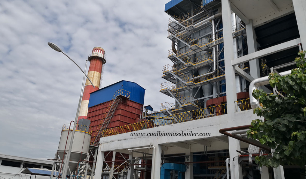
Taishan Group Coal-Fired Hot Oil Boiler Successfully Exported to Indonesia

Taishan Group Coal-Fired Hot Oil Boiler Successfully Exported to Indonesia

Taishan Group, a leading supplier of hot oil boilers and steam boilers, has successfully delivered a coal-fired thermal oil boiler to Best Industry Group, one of the largest palm oil refineries in Indonesia. The YLW-2300MA model coal-fired hot oil boiler, with a capacity of 2,000,000 kcal/h, ensures efficient and stable thermal energy supply for the palm oil production process.

Technical Specifications of the Coal-Fired Hot Oil Boiler

ParameterDetails
Boiler NameOrganic Fluid Boiler
ModelYLW-2300MA
Rated Thermal Power2300 kW
Working Pressure0.8 MPa
Design Pressure1.1 MPa
Max Working Temperature320°C
Medium Circulation Amount160 m³/h
Medium Volume3.5 m³
Design FuelA-ll Soft Coal
Lower Heating Value5500 kcal/kg
Fuel Consumption455 kg/h
Thermal Efficiency80.15%
Overall Size6500 × 2500 × 4600 mm
Total Weight34,385 kg
Case 11

Best Industry Group – A Leading Palm Oil Manufacturer

Best Industry Group has been a key player in Indonesia’s vegetable oil industry since 1982, specializing in palm oil production. Originally transitioning from coconut oil to palm oil, the company rapidly expanded its market share across East Java, Bali, West Nusa Tenggara, Central Java, West Java, Jakarta, and Sumatra. Today, the company exports palm cooking oil to China and various European countries, reinforcing its position as an internationally recognized brand.

Taishan Group has a long-standing partnership with Best Industry Group, having previously exported over 40 sets of coal-fired boilers, including:
10-30t/h steam boilers
2,000,000-6,000,000 kcal/h hot oil boilers

Global Leadership in Industrial Boiler Solutions

As a world-leading manufacturer of coal-fired and biomass boilers, Taishan Group provides customized industrial boiler solutions and power plant boilers for international clients. With partners in over 36 countries and regions, Taishan Group remains committed to delivering:
High-quality and efficient boiler solutions
Reliable and energy-saving thermal oil systems
Comprehensive after-sales service and technical support

🔹 Looking for a high-performance coal-fired hot oil boiler? Contact us today at sales@coalbiomassboiler.com for expert consultation and tailored solutions!

Andy Zhao

Senior Sales Manager
30+ boiler projects experience, focus on high-end customization, non-standard & special fuel boiler sales. Representative projects include waste heat boilers for Russian EVRAZ Steel, Coal CFB Boiler for Indonesia QMB New Energy Materials, HP drum & LP drum For Italian Nooter/Erisken, MP drum for Korean Hyundai Steel, LP drum for Korean POSCO Steel, 2 sets Air Cooling Coil for Finland Metso. Boiler Sales in Africa, Central Asia, Taiwan, etc.

Taishan Group Coal-Fired Hot Oil Boiler Successfully Exported to Indonesia Read More »
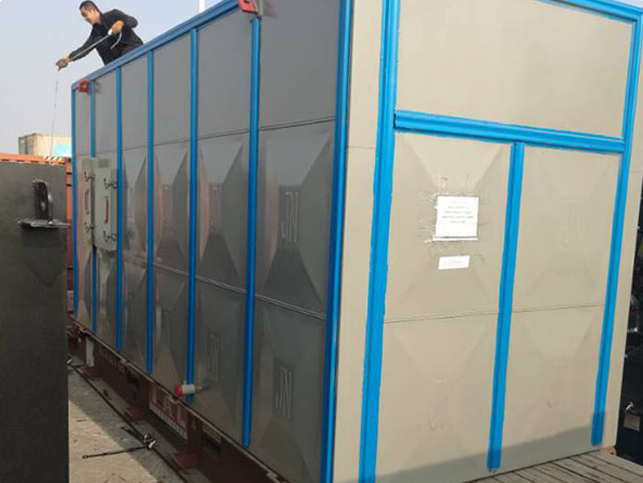
Taishan Group Chain Grate Boiler Successfully Operating in Pakistan’s Food Industry

Taishan Group Chain Grate Boiler Successfully Operating in Pakistan’s Food Industry

Chain grate boilers are among the most widely used coal-fired boilers, known for their efficiency, durability, and stable steam output. In July 2016, Taishan Group exported two coal-fired steam boilers to a leading food manufacturer in Multan, Pakistan. These included:

  • SZL25-1.6-All: 25t/h, 1.6MPa, double-drum, longitudinal layout, water tube chain grate boiler

  • DZL10-1.6-All: 10t/h, 1.6MPa, single-drum, longitudinal layout, water and fire tube chain grate boiler

After successful installation, commissioning, and trial operation in January 2018, both coal-fired boilers were put into operation, ensuring a stable steam supply for the packaging and drying processes of the food production line.

Case 10.1

Reliable Steam Supply for a Leading Food Manufacturer in Pakistan

The Multan-based food manufacturer is a well-established enterprise with over 5,000 employees and strong market influence in Pakistan’s food industry. The company has been a loyal customer of Taishan Group, sourcing coal-fired chain grate boilers from China for many years.

In 2012, the company purchased a 10t/h 1.6MPa coal boiler (SZL10-1.6-All), which has been operating smoothly and efficiently ever since. Impressed by the high quality and reliability of Taishan’s boilers, the company expanded its production in 2016, leading to another contract for:

  • 25t/h 1.6MPa coal-fired boiler (SZL25-1.6-All)

  • 4t/h 1.6MPa coal-fired chain grate boiler (DZL4-1.6-All)

Case 10.2

Long-Term Cooperation and Commitment to Quality

Since the first purchase contract in 2012, Taishan Group has maintained a strong and trustworthy relationship with this Pakistani food manufacturer. The company values boiler efficiency, durability, and steam stability, which have been key factors in their continued partnership.

Moving forward, Taishan Group remains committed to delivering:
Superior product quality for high-performance steam boilers
Tailored boiler solutions to meet specific industrial needs
Reliable after-sales support to ensure long-term efficiency

Your Trusted Partner for Chain Grate Boilers

As a leading manufacturer of coal-fired boilers and biomass boilers, Taishan Group provides:
Custom boiler design & fabrication
High-efficiency energy solutions
Professional installation & after-sales service

For inquiries about high-performance coal-fired boilers, contact us at sales@coalbiomassboiler.com—we are ready to assist you!

Andy Zhao

Senior Sales Manager
30+ boiler projects experience, focus on high-end customization, non-standard & special fuel boiler sales. Representative projects include waste heat boilers for Russian EVRAZ Steel, Coal CFB Boiler for Indonesia QMB New Energy Materials, HP drum & LP drum For Italian Nooter/Erisken, MP drum for Korean Hyundai Steel, LP drum for Korean POSCO Steel, 2 sets Air Cooling Coil for Finland Metso. Boiler Sales in Africa, Central Asia, Taiwan, etc.

Taishan Group Chain Grate Boiler Successfully Operating in Pakistan’s Food Industry Read More »
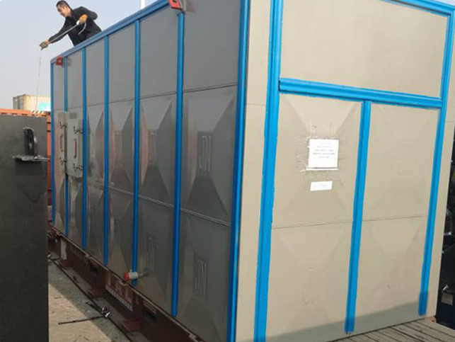
Taishan Group CFB Steam Boiler for EPC Project Successfully Running in Vietnam

Taishan Group CFB Steam Boiler for EPC Project Successfully Running in Vietnam

Taishan Group’s CFB Steam Boiler is a widely adopted solution for power generation across various industries. In 2017, Taishan Group secured a major CFB Steam Boiler EPC contract from a leading tyre manufacturer in Vietnam. The project involved supplying a DHX35-2.45-All model CFB steam boiler, featuring a 35-ton per hour steam capacity, a 2.45MPa steam pressure, and the capability to use soft coal as fuel.

Case 9.1

Vietnam Tyre Factory – A Leading Global Tyre Manufacturer

This CFB steam boiler project is located in Go Dau County, Tay Ninh Province, Vietnam, marking a significant investment in Vietnam’s tyre manufacturing industry. The factory is part of a globally recognized tyre production group that has expanded its operations through strategic mergers. It became the first A-listed private Chinese enterprise on the Shanghai Stock Exchange. The group operates modern tyre manufacturing bases in China (Qingdao, Dongying, Shenyang, Xining) and Vietnam, along with an OTR tyre production base in Thailand.

With an annual production capacity of:

  • 4.2 million TBR tyres

  • 32 million PCR tyres

  • Over 40,000 tons of OTR tyres

Their products are exported to over 100 countries worldwide, reinforcing their reputation as a global leader in the tyre industry.

Taishan Group’s First International CFB Steam Boiler EPC Project

This Vietnam EPC project is a milestone for Taishan Group, marking its first overseas CFB steam boiler EPC contract. The project scope covered:
System design
CFB boiler manufacturing
Logistics and delivery
On-site installation
Commissioning and acceptance

Taishan Group is a qualified EPC contractor, having obtained the Grade II Thermal Power Plant Design Qualification.

Case 9.2

Efficient Project Execution and High Customer Satisfaction

Following the contract signing, Taishan Group promptly initiated the CFB boiler design, production, and logistics planning. The installation team ensured seamless assembly and commissioning. Within just six months, the CFB steam boiler was successfully installed and operational, receiving high praise from the client for its efficiency and reliability.

With this successful CFB Steam Boiler EPC project in Vietnam, Taishan Group continues to expand its global footprint in the industrial boiler industry, delivering high-performance, energy-efficient steam solutions for international clients.

Why Choose Taishan Group for Your CFB Steam Boiler EPC Needs?

🔹 Industry-Leading Expertise – Decades of experience in CFB steam boiler manufacturing and EPC solutions
🔹 Customized Boiler Solutions – Tailored to meet specific industrial power needs
🔹 Proven Global Success – Trusted by clients in over 100 countries
🔹 Fast and Reliable Execution – Efficient project management, from design to commissioning

Looking for a high-performance CFB steam boiler for your industrial power generation needs? Contact Taishan Group today!

Andy Zhao

Senior Sales Manager
30+ boiler projects experience, focus on high-end customization, non-standard & special fuel boiler sales. Representative projects include waste heat boilers for Russian EVRAZ Steel, Coal CFB Boiler for Indonesia QMB New Energy Materials, HP drum & LP drum For Italian Nooter/Erisken, MP drum for Korean Hyundai Steel, LP drum for Korean POSCO Steel, 2 sets Air Cooling Coil for Finland Metso. Boiler Sales in Africa, Central Asia, Taiwan, etc.

Taishan Group CFB Steam Boiler for EPC Project Successfully Running in Vietnam Read More »
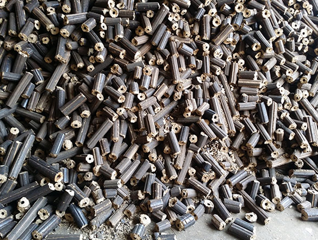
Taishan Group Showcases Coal-Fired Boilers at IGATEX Pakistan to Boost Textile Industry Demand

Taishan Group Showcases Coal-Fired Boilers at IGATEX Pakistan to Boost Textile Industry Demand

Expanding Presence in Karachi’s Textile Industry

While Karachi has historically had stable gas supply, limiting the demand for coal-fired boilers, we have steadily developed the market. In 2019, Taishan Group and our agent jointly established an office in Karachi to strengthen our sales of coal steam boilers for industrial applications.

From 2019 to 2021, Taishan successfully delivered 10 sets of coal-fired steam boilers to major textile factories in Karachi, with capacities ranging from 10 tons to 25 tons, making us a reliable boiler supplier in Pakistan.


Strong Interest from Major Textile Companies at IGATEX

During IGATEX 2021, our agent actively promoted industrial steam boilers to local and visiting companies. The booth attracted large textile enterprises from Karachi who showed strong interest in our high-performance and cost-effective coal boilers. Many expressed plans to visit our existing boiler installations after the event.

Our long-standing customers also visited the booth and praised the quality and efficiency of our products. They confirmed that Taishan Group remains their preferred coal boiler supplier for future projects.

新闻11

Reliable After-Sales Service in Pakistan

Our exclusive agent in Pakistan, STEAMMASTERS, continues to offer after-sales support and maintenance to ensure smooth boiler operation. After the exhibition, our agent scheduled several follow-up visits to prospective buyers to discuss procurement plans for new coal-fired boilers.


Why Choose Taishan Coal-Fired Steam Boilers for Textile Applications?

  • High Efficiency: Optimized combustion system for maximum energy utilization.
  • Tailored Solutions: Custom design for specific textile processes.
  • Proven Performance: Successful operations across Pakistan’s textile hubs.
  • Cost-Effective Energy: Competitive alternative to gas boilers in regions with limited gas supply.

Get in Touch with a Trusted Coal Boiler Manufacturer

If you are looking for a reliable coal steam boiler for textile industry or other industrial boiler solutions, Taishan Group offers a full range of customized, high-quality boilers to meet your plant’s needs. Visit our website for detailed product specifications and customer case studies: https://coalbiomassboiler.com/

Andy Zhao

Senior Sales Manager
30+ boiler projects experience, focus on high-end customization, non-standard & special fuel boiler sales. Representative projects include waste heat boilers for Russian EVRAZ Steel, Coal CFB Boiler for Indonesia QMB New Energy Materials, HP drum & LP drum For Italian Nooter/Erisken, MP drum for Korean Hyundai Steel, LP drum for Korean POSCO Steel, 2 sets Air Cooling Coil for Finland Metso. Boiler Sales in Africa, Central Asia, Taiwan, etc.

Taishan Group Showcases Coal-Fired Boilers at IGATEX Pakistan to Boost Textile Industry Demand Read More »

ASME Certified Waste Heat Boiler Successfully Delivered to South Korea for Steel Industry Giants POSCO and Hyundai

ASME Certified Waste Heat Boiler Successfully Delivered to South Korea for Steel Industry Giants POSCO and Hyundai

As a leading industrial boiler manufacturer in China, Taishan Group proudly completed the delivery of an ASME-certified waste heat boiler system to South Korea. This milestone marks our first successful shipment of steam boilers to the Korean market, setting the stage for long-term cooperation with top-tier steel producers like POSCO and Hyundai Steel.

What is a Waste Heat Boiler?

A waste heat boiler is a high-efficiency energy recovery solution that utilizes the hot flue gas from upstream industrial processes to produce steam. It plays a critical role in energy conservation, thermal efficiency enhancement, and environmental protection. Waste heat boilers are widely used in steel plants, chemical factories, cement manufacturing, and other heavy industries.

Each waste heat boiler must be custom-designed to match the unique flue gas conditions of the facility — including temperature, pressure, flow, and dust content — requiring manufacturers with rich expertise and strong technical capabilities.


Project Overview: Waste Heat Boiler Export to South Korea

In April 2020, Taishan Group received an order from a Korean client for multiple boiler components related to HRSG (Heat Recovery Steam Generator) systems. The order included:

  • Four steam drums
  • One deaerator
  • Two blowdown tanks
  • One flue gas duct

These components were manufactured according to ASME standards, ensuring full compliance with international regulations and performance expectations. The final users are none other than POSCO and Hyundai Steel, both of which are globally renowned steel manufacturers.

After nearly five months of meticulous design and precision fabrication, all equipment has been shipped and arrived safely at the project site, ready for installation and commissioning.

案例8.1
 Key Product Highlights

Here is a summary of the technical specifications of the waste heat boilers for POSCO and Hyundai Steel:

POSCO Waste Heat Boiler Specifications
ItemData
Design StandardASME Section I Edition 2017
Steam Flow18 t/h
Design Pressure19 barg
MAWP (Max Allowable Working Pressure)19 barg
Test Pressure28.5 barg
Design Temperature212°C
Operating Temperature212°C
MediumWater / Steam
Total Contents11,500 L
Corrosion Allowance1 mm
Hyundai Steel Waste Heat Boiler Specifications
ItemData
Design StandardASME Section VIII Div.1 Edition 2017
Steam Flow26.3 t/h
Design Pressure30 barg
MAWP (Max Allowable Working Pressure)30 barg
Test Pressure40 barg
Design Temperature236°C
Operating Temperature236°C
Minimum Design Metal Temperature+4°C
MediumWater / Steam
Total Contents16,900 L
Corrosion Allowance1 mm
案例8.2
 Why Choose Taishan Group as Your Waste Heat Boiler Supplier?
  • ASME-certified manufacturer with a strong track record in industrial steam boiler fabrication.
  • Over 40 years of experience serving global markets with high-quality thermal energy solutions.
  • Customized engineering based on customer specifications and local operating conditions.
  • Rich project experience in steel industry, power plants, cement plants, and chemical sectors.
  • Dedicated project teams offering full-cycle service from design to after-sales support.

Strengthening Global Partnerships

This delivery not only reflects the trust and confidence that major Korean enterprises place in Taishan Group, but also showcases our technical strength and manufacturing excellence in waste heat recovery solutions. We are committed to further developing our presence in the South Korean industrial boiler market and warmly welcome future cooperation opportunities from companies in Asia and beyond.

If you’re looking for a reliable waste heat boiler manufacturer or need customized ASME-certified steam boiler solutions, don’t hesitate to contact us or visit our official website for more details.https://coalbiomassboiler.com/

Andy Zhao

Senior Sales Manager
30+ boiler projects experience, focus on high-end customization, non-standard & special fuel boiler sales. Representative projects include waste heat boilers for Russian EVRAZ Steel, Coal CFB Boiler for Indonesia QMB New Energy Materials, HP drum & LP drum For Italian Nooter/Erisken, MP drum for Korean Hyundai Steel, LP drum for Korean POSCO Steel, 2 sets Air Cooling Coil for Finland Metso. Boiler Sales in Africa, Central Asia, Taiwan, etc.

ASME Certified Waste Heat Boiler Successfully Delivered to South Korea for Steel Industry Giants POSCO and Hyundai Read More »

Taishan Group First 440TPH Pulverized Coal Furnace Drum Successfully Delivered

Taishan Group First 440TPH Pulverized Coal Furnace Drum Successfully Delivered

 A Major Milestone in Taishan Group’s Industrial Boiler Manufacturing Capabilities

On October 22, 2023,  Taishan Group, a global leader in industrial boiler manufacturing, successfully completed and delivered the first 440 tons per hour (TPH) pulverized coal boiler steam drum. This marks a significant step forward in our ability to deliver high-capacity, high-performance components for power plants and large-scale industrial steam systems.

Also known as a pulverized fuel boiler, coal powder boiler, or powdered coal furnace, this type of coal-fired boiler is designed for the efficient combustion of pulverized coal, offering high thermal efficiency, stable operation, and low emissions—making it an ideal choice for modern industrial energy systems and thermal power stations.

新闻10

🔍 Key Product Highlights

ItemDetails
Product TypePulverized Coal Boiler Steam Drum
Capacity440 Tons Per Hour (TPH)
Drum SizeDN1600 × 65 × 14,650 mm
Weight51.5 Tons
Material13MnNiMo54 (High-Strength Alloy Steel)
Design StandardASME Certified
ApplicationThermal Power Plants, Industrial Steam Systems

🛠️ Complex Design, Precision Manufacturing

The steam drum’s production posed unique technical challenges due to its:

  • Large size and high-pressure resistance
  • Complex internal structure
  • High-alloy steel material with strict quality requirements
  • Numerous processing and testing steps

To ensure successful delivery, Taishan Group mobilized its top engineering and manufacturing teams. Group Chairman personally visited the production workshop multiple times for on-site supervision and guidance—despite the intense summer heat.

Before fabrication began, a series of technical review and deployment meetings were held. Senior engineers explained the manufacturing plan, process difficulties, and risk management strategies to the workshop staff. A dedicated project team was formed to ensure real-time monitoring, feedback, and resolution of critical technical issues.


🔧 Collaboration & Quality Control

  • The main production workshop tracked and assessed the quality and time nodes of each process.
  • The welding team overcame extreme weather conditions to complete precision manual welding.
  • Each phase of manufacturing followed strict ASME and internal quality standards to ensure the safety, durability, and performance of the final product.

Thanks to this coordinated, high-efficiency approach, the project was delivered on time and with full quality assurance.


🌍 Why It Matters: Global Impact & Innovation

This successful delivery represents much more than the completion of one component—it reflects Taishan Group’s growing capability to serve international markets with high-end, customized industrial boiler equipment. It also builds valuable experience for the future manufacturing of large-scale, high-tech boiler parts, especially for pulverized coal-fired boiler systems.

With increasing global demand for cleaner, more efficient energy solutions, the use of pulverized coal boilers is gaining traction due to their:

  • Higher combustion efficiency
  • Lower pollutant emissions
  • Better control of fuel economy

🚀 Looking Ahead

Moving forward, Taishan Group will continue to:

  • Expand investment in R&D and innovation
  • Upgrade its smart manufacturing systems
  • Offer tailor-made boiler system solutions for customers across power generation, petrochemical, metallurgical, and other industries

This milestone is another strong step in our journey to achieve a “Five-Year Leap Forward” development strategy and to continue leading the field of global industrial boiler manufacturing.

Andy Zhao

Senior Sales Manager
30+ boiler projects experience, focus on high-end customization, non-standard & special fuel boiler sales. Representative projects include waste heat boilers for Russian EVRAZ Steel, Coal CFB Boiler for Indonesia QMB New Energy Materials, HP drum & LP drum For Italian Nooter/Erisken, MP drum for Korean Hyundai Steel, LP drum for Korean POSCO Steel, 2 sets Air Cooling Coil for Finland Metso. Boiler Sales in Africa, Central Asia, Taiwan, etc.

Taishan Group First 440TPH Pulverized Coal Furnace Drum Successfully Delivered Read More »

Coal and Biomass Fuel Hot Oil Boiler Running in Pakistan

Coal and Biomass Fuel Hot Oil Boiler Running in Pakistan

Hot oil boiler is another name of thermal oil boiler, thermal oil heater, thermal fluid heater, thermal fluid boiler, thermal oil furnace, thermic fluid heater, hot oil heater. Thermal oil boiler and steam boiler manufacturer Taishan Group won two projects in abroad. One is 2,000,000kcal/h capacity biomass fuel (rice husk rod) thermal oil boiler in Bangladesh. Another is 2,000,000kcal/h and 4,000,000kcal/h capacity coal fired hot oil boiler in Pakistan. Below I will take the 4,000,000kcal/h thermal oil furnace as an example, and introduce its full detailed technical parameters.

新闻9.1
Detailed parameters of coal hot oil boiler

Name: Organic heat carrier boiler
Model: YLW-4700MA
Rated thermal power: 4700kW
Working pressure: 0.8MPa
Design pressure: 1.1MPa
Max working temperature: 320℃
Working medium: heat transfer oil
Medium circulation amount: 260m³/h
Medium volume: 6.5m³
Design fuel: soft coal
Lowering heating value: 5500kcal/kg
Fuel consumption: 910kg/h
Thermal efficiency: 80.1%
Overall size: 7750x3200x5200mm
Total weight: 54255kg
Transport size: 6900x3200x3200mm / 7750x3038x2000mm
Transport weight: 18386kg / 19317kg

FD fan: model GG10-1, flow 10000-22500m³/h, pressure 2690-1620Pa, power 15kW
ID fan: model GY10-15, flow 26320-32140m³/h, pressure 3802-3714Pa, power 55kW
Circulating oil pump: model WRY125-100-257, flow 260m³/h, head 70m, power 75kW
Oil filling pump: model 2CY3.3/3.3-1, flow 3.3m³/h, pressure 0.32MPa, power 1.5kw
Y-type oil filter: model YG41-16C, size DN200
Oil-gas separator: model FL200
Expansion tank: volume 4.5m³
Oil storage tank: volume 10m³
Grate gear governor: model GL-16P, power 1.1kW
Spiral slag remover: model CZX-6, power 1.5kW
Lifting coal feeder: model SMT-400, power 2.2kW
Chimney: diameter 600mm, height 18m
Multi-tube dust collector: model XZD-8, exhaust flow: 24000m3/h, dedusting efficiency 95%
Wet scrubber: model GXS-8, exhaust flow: 24000m3/h, desulfurizing efficiency 80%

So far, we have exported over thirty sets of coal and biomass fuel thermal oil boilers to Pakistan and Bangladesh. The capacity ranges from 2,000,000 kcal/h to 6,000,000kcal/h

Andy Zhao

Senior Sales Manager
30+ boiler projects experience, focus on high-end customization, non-standard & special fuel boiler sales. Representative projects include waste heat boilers for Russian EVRAZ Steel, Coal CFB Boiler for Indonesia QMB New Energy Materials, HP drum & LP drum For Italian Nooter/Erisken, MP drum for Korean Hyundai Steel, LP drum for Korean POSCO Steel, 2 sets Air Cooling Coil for Finland Metso. Boiler Sales in Africa, Central Asia, Taiwan, etc.

Coal and Biomass Fuel Hot Oil Boiler Running in Pakistan Read More »

Scroll to Top
Taishan Group
Make an appointment with us to meet at exhibition
Quick Contact

Get Quick Support