Industry News

What Are the Essential Parameters for Selecting a Power Plant Boiler?
What Are the Essential Parameters for Selecting a Power Plant Boiler?

Selecting the right boiler for a power plant is a critical engineering decision with long-term impacts on performance, reliability, efficiency, and environmental compliance. Choosing the wrong configuration can result in poor output, excessive emissions, costly downtime, and inflated operating costs. With so many options available—circulating fluidized bed (CFB), pulverized coal, supercritical, biomass, and more—what parameters really matter when selecting a power plant boiler?

The essential parameters for selecting a power plant boiler include steam output capacity, pressure and temperature requirements, fuel type and availability, boiler efficiency, emission compliance standards, and operational flexibility. These criteria ensure the boiler aligns with the power plant’s technical, environmental, and economic goals.

To avoid costly miscalculations, plant designers, procurement teams, and energy strategists must carefully evaluate all technical and logistical aspects. Read on as we break down the most important parameters that guide successful boiler selection for power generation.
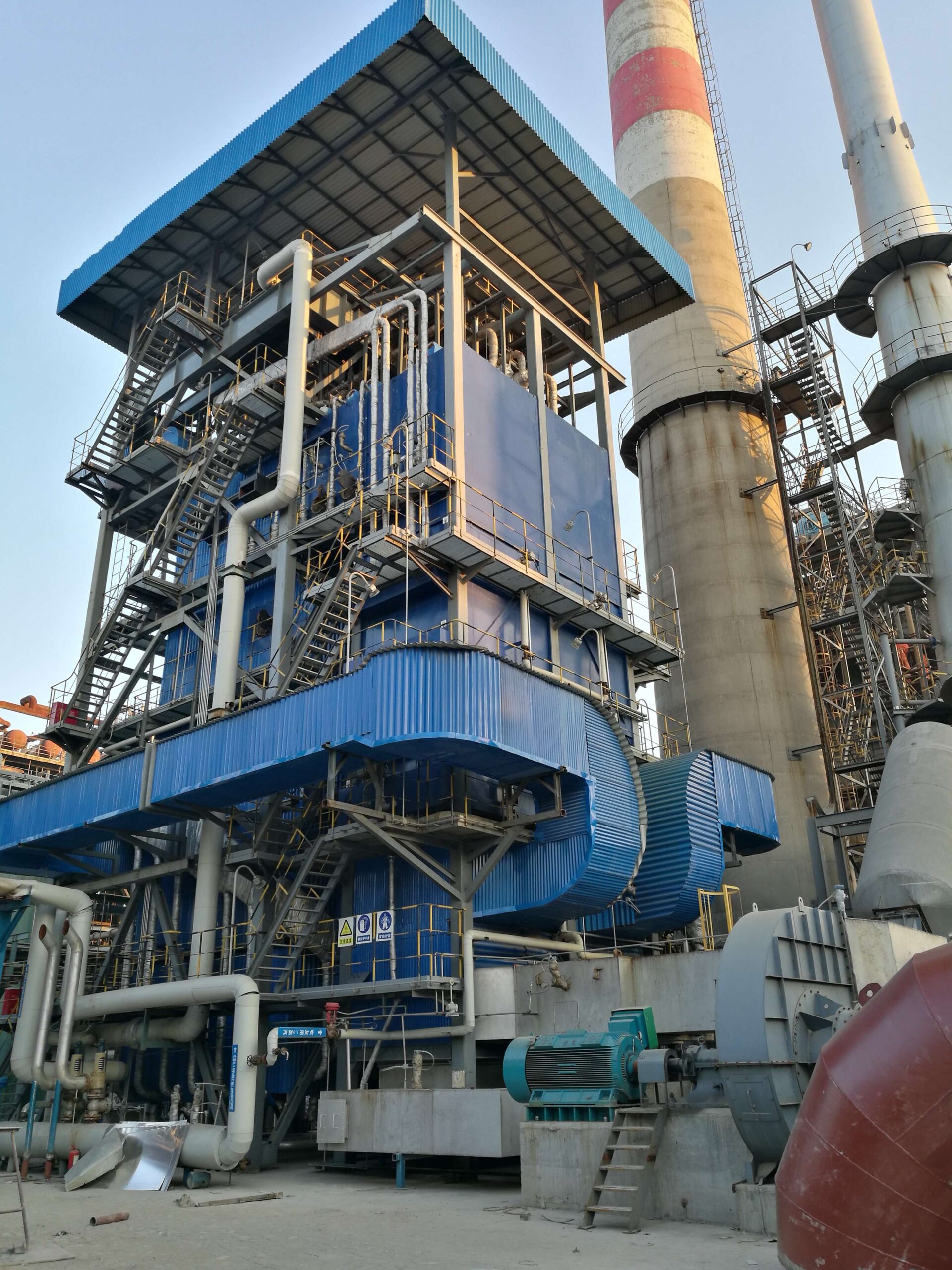
Why Is Steam Output Capacity a Critical Parameter for Power Plant Boiler Selection?

In the high-stakes world of power generation, the heart of the plant is the boiler—the unit responsible for converting chemical energy from fuel into high-pressure, high-temperature steam. This steam drives turbines, which generate electricity. A mismatch between boiler steam output capacity and plant load demand can lead to disastrous inefficiencies, bottlenecks, safety risks, or even structural damage. Simply put, steam output capacity is not just a specification—it’s the foundation of boiler performance, system integration, and long-term operational success.

Steam output capacity is a critical parameter for power plant boiler selection because it determines the volume of steam the boiler can generate at a given pressure and temperature to match the turbine’s load demand. Undersized boilers lead to power deficits, turbine instability, and overloading; oversized boilers suffer from cycling losses, poor combustion efficiency, and higher capital costs. Properly matching steam output to plant requirements ensures stable operation, optimal thermal efficiency, and reliable electricity generation.

Whether designing a new facility or upgrading an existing one, the steam capacity specification is the first and most crucial decision in boiler selection.

The steam output capacity of a boiler determines how much power the plant can generate.True

Boilers convert fuel into steam, which drives turbines to produce electricity. The more steam generated at the correct parameters, the higher the generation capacity.

Over-sizing a power plant boiler improves operational flexibility without efficiency losses.False

Oversized boilers may experience frequent low-load operation, cycling losses, and poor combustion performance, reducing efficiency and increasing wear.

🔍 What Is Steam Output Capacity?

Steam output capacity refers to the mass flow rate of steam a boiler can generate per unit time at a specified pressure and temperature.

MetricTypical UnitsUse
Steam OutputTons per hour (TPH)Sizing for power generation and process use
PressureBar or MPaDetermines turbine inlet conditions
Temperature°C (saturated/superheated)Affects thermal efficiency and turbine power

Boiler designs for power plants typically range from:

  • Industrial Boilers: 20–150 TPH

  • Utility Boilers: 200–2,000+ TPH

  • Ultra-Supercritical Units: >2,500 TPH


📊 Boiler Size vs. Turbine Demand Matching

Boiler Output (TPH)Steam ConditionsSupports Turbine Output (MW)
50 TPH60 bar, 450°C10–15 MW
150 TPH90 bar, 510°C30–50 MW
500 TPH135 bar, 540°C120–150 MW
1,000+ TPH250+ bar, 600°C300+ MW

The steam generation rate must align with turbine inlet flow requirements; otherwise, the turbine cannot maintain speed, pressure, and output under varying grid loads.


⚠️ Consequences of Incorrect Steam Capacity Selection

Undersized BoilerOversized Boiler
Cannot meet peak demandRuns inefficiently at low load
Frequent boiler trips or alarmsHigh capital and operating costs
Excessive pressure drop or steam starvationCombustion inefficiency and temperature swings
Reduced power output or turbine deratingIncreased wear from cycling and turn-down issues

In either case, the entire plant’s performance suffers—from grid reliability to emissions compliance.


🔧 Key Factors in Steam Output Capacity Calculation

🔹 1. Turbine Steam Flow Requirements

  • Must match the boiler steam capacity under full and part-load conditions

  • Consider steam bypass and venting provisions

🔹 2. Fuel Type and Calorific Value

  • Different fuels (coal, biomass, gas) have varying heat release characteristics

  • Low-CV fuels require larger boilers to generate the same steam output

🔹 3. Boiler Type

TypeBest Use Case
Water-Tube BoilerHigh capacity, high pressure
Once-Through BoilerSupercritical applications
Pulverized Coal BoilerLarge-scale baseload generation

🔹 4. Boiler Efficiency

  • A 90% efficient boiler generates more usable steam than an 82% efficient one using the same fuel

  • Impacts fuel consumption and operating cost


🧪 Real-World Example: Capacity Mismatch in a Cogeneration Plant

Plant Profile: 30 MW CHP facility using a 100 TPH coal-fired boiler
Issue: Boiler rated at 85 TPH installed to save cost
Results:

MetricExpectedActualImpact
Turbine Load (MW)3021–2420–30% capacity loss
Steam Pressure (bar)9075Inadequate turbine pressure
Efficiency (%)8678Fuel penalty of 10%
Downtime/Year (hrs)140Frequent boiler trips

Solution: Retrofitted an auxiliary boiler + optimized steam distribution → Full power output restored with improved load flexibility.


📈 Best Practices for Sizing and Managing Steam Output Capacity

✅ Perform Detailed Steam Demand Analysis

  • Analyze base, peak, and emergency steam loads

  • Include safety margins and future load growth

  • Model load profiles (hourly, daily, seasonal)

✅ Match Boiler-Turbine-Grid Integration

  • Ensure turbine steam requirements are met under ramping and steady-state

  • Use modulating controls for better turndown

  • Implement steam bypass stations for redundancy

✅ Use Modular Boiler Design (if appropriate)

  • Multiple small boilers offer better turndown and N+1 redundancy

  • Easier maintenance scheduling

  • Lower startup time and emissions during partial loads

✅ Combine with Heat Recovery Options

  • Maximize efficiency by integrating with economizers and air preheaters

  • Use condensate recovery to reduce water and energy losses

  • Consider combined heat and power (CHP) configurations


🌍 Impact on Efficiency, Emissions, and O&M

AspectWell-Matched CapacityPoorly Sized Capacity
Boiler Thermal Efficiency87–92%75–82%
Fuel Consumption (tons/day)Optimized for actual loadExcess due to cycling/inefficiency
Turbine Power OutputStable, predictableVolatile, derated
Emissions (NOₓ, CO₂)Lower per MWhHigher due to poor combustion
Maintenance CostsLower due to fewer tripsHigher due to thermal stress

📌 Technical Checklist for Capacity Matching

  • Define peak and base load steam requirements

  • Specify required pressure and temperature

  • Include load variation in sizing (turn-down ratio)

  • Evaluate fuel characteristics and system efficiency

  • Assess integration with turbines and process equipment

  • Ensure space and weight compatibility

  • Factor in redundancy, maintenance, and future expansion

  • Run simulations for both steady-state and transient loads


Steam output capacity is the most critical specification when selecting a power plant boiler—it determines the reliability, efficiency, cost-effectiveness, and flexibility of the entire generation system. By accurately defining your steam needs and choosing a boiler that meets those needs under all operating conditions, you ensure long-term performance, fuel savings, and regulatory compliance.
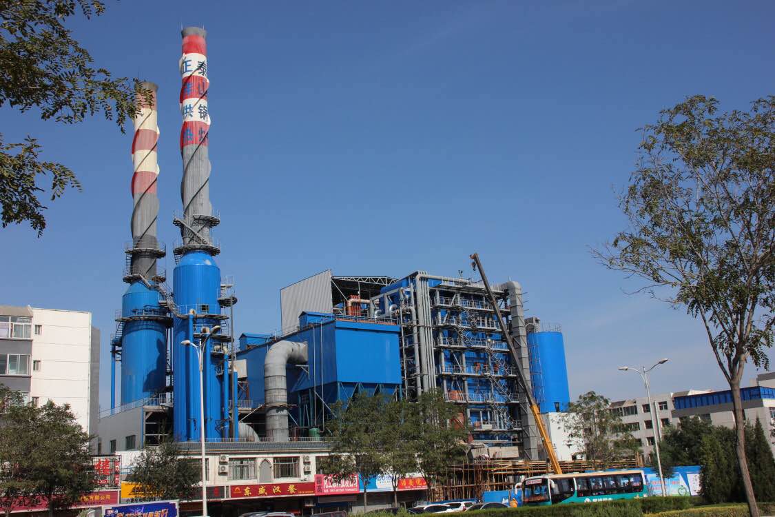
How Do Pressure and Temperature Specifications Influence Boiler Design and Performance?

Industrial boilers, particularly in high-demand sectors like power generation, oil refining, and chemical processing, are not one-size-fits-all systems. One of the most defining aspects of their design and long-term performance is the operating pressure and steam temperature they’re expected to deliver. These specifications determine the structural integrity, thermal efficiency, material selection, fuel usage, and even the type of turbine or downstream process that can be supported. Selecting inappropriate pressure or temperature parameters can lead to inefficiencies, safety risks, and costly equipment failure.

Pressure and temperature specifications directly influence boiler design and performance by defining the strength, material composition, thermal efficiency, and energy conversion potential of the system. Higher steam pressure and temperature improve thermal efficiency by allowing more energy to be extracted per unit of fuel but require stronger materials, advanced safety controls, and precise engineering. Boiler components such as drums, tubes, and headers must be engineered to withstand elevated thermal and mechanical stresses. Ultimately, pressure and temperature specifications dictate the boiler’s operational range, efficiency, maintenance needs, and lifecycle cost.

Designing a boiler without aligning it to the correct steam parameters is like building a car without knowing its top speed—it compromises every performance metric.

Higher boiler pressure and temperature increase thermal efficiency in steam cycles.True

Increasing pressure and temperature raises the enthalpy difference across turbines, improving energy conversion efficiency.

Boilers operating at higher pressures require the same design standards as low-pressure boilers.False

High-pressure boilers need enhanced materials, thicker walls, specialized welding, and more rigorous safety protocols.

🔍 The Thermodynamic Foundation: Why Pressure and Temperature Matter

The performance of a steam boiler is fundamentally tied to the Rankine cycle, which converts thermal energy into mechanical energy via steam expansion.

Steam ParameterInfluence on Boiler Design & Performance
Pressure (bar/MPa)Affects boiler wall thickness, drum design, and water-circulation patterns
Temperature (°C)Dictates material selection for superheaters, valves, and turbines
Steam QualityImpacts turbine lifespan, plant efficiency, and energy transfer

Higher pressure and temperature = higher steam enthalpy = more electricity per kg of steam


📊 Comparison: Boiler Design by Pressure/Temperature Range

Boiler ClassOperating PressureSteam TemperatureApplications
Low-Pressure Boiler<10 bar<180°CHVAC, laundry, small processes
Medium-Pressure Boiler10–45 bar180–300°CFood processing, small power plants
High-Pressure Boiler45–130 bar300–540°CIndustrial cogeneration, refineries
Supercritical Boiler220+ bar>600°CUtility-scale power generation

Higher categories allow for greater energy efficiency but require more complex design, monitoring, and control systems.


🔧 Engineering Implications of Pressure & Temperature Specs

🔸 1. Material Selection

ParameterDesign Impact
Pressure >60 barRequires chrome-molybdenum steel or alloyed tubes
Temperature >540°CUse of creep-resistant alloys like T91, Super304H, or Inconel
Fluctuating LoadsMaterials must handle thermal cycling and fatigue

🔸 2. Wall Thickness & Welding

  • Boiler walls must be thicker and precisely welded to resist stress

  • High-pressure systems follow ASME Section I and EN 12952 standards

  • Poorly designed welds in high-stress zones lead to creep failure or rupture

🔸 3. Water Circulation

  • Natural circulation is limited in high-pressure designs

  • 130 bar: forced circulation or once-through designs are required

  • Incorrect design causes tube overheating or drum priming


⚙️ Performance Impacts by Pressure & Temperature Range

SpecLow P/T BoilerHigh P/T Boiler
Thermal Efficiency (%)75–80%88–92%
Turbine Output (MW/TPH)6–810–12
Fuel ConsumptionHigherLower
Startup TimeShorterLonger (due to heating)
Maintenance ComplexityLowerHigher (materials, sensors)

While high-pressure boilers are more efficient, they come with greater operational discipline and cost.


🧪 Case Study: Boiler Upgrade for Higher Pressure and Temperature

Industry: Pulp and Paper
Old Boiler: 60 bar / 450°C → New Boiler: 105 bar / 525°C

MetricBeforeAfterImprovement
Steam Efficiency (kg/kWh)5.14.4+13.7%
Fuel Consumption (tons/day)11094-14.5%
CO₂ Emissions (tons/day)284243-14.4%
Steam Turbine Output (MW)1822+22.2%

ROI: ~2.2 years from fuel and emissions savings alone


🔍 Design Parameters That Must Align with Steam Specs

ComponentConsiderations for High P/T Design
Drums and ShellsMust resist internal and external pressure loads
Headers & NozzlesDesigned to avoid thermal stress fractures
Safety ValvesCalibrated for high-set pressure + rapid release
Tube BendsUse long-radius bends to avoid creep stress
Refractory & InsulationWithstand sustained 500°C+ surface temps

Improper design causes hot spots, tube failures, or system shutdowns under elevated load.


📈 Operational & Efficiency Strategies for High Pressure/Temperature Boilers

✅ Use oxygen trim control to optimize combustion at higher temps
✅ Install real-time monitoring of tube skin temperatures
✅ Apply AI-driven control loops for better load tracking
✅ Maintain feedwater quality to prevent stress-corrosion cracking
✅ Ensure daily blowdown and scale prevention routines
✅ Monitor creep life and stress margins in critical components


🌍 Environmental and Lifecycle Impact

Design ChoiceImpact Over 20-Year Lifecycle
High Pressure & Temp Design~20% lower fuel use
Improved Combustion EfficiencyReduced NOₓ and SO₂ emissions by 10–20%
Optimized Superheater SpecReduces excess stack temperature and heat losses
Longer Operational RangeAvoids derating during high demand or grid surges

A properly engineered high-P/T boiler pays back in fuel savings, emissions reduction, and longer operating windows—even with higher upfront costs.


🧩 Summary: Matching Steam Specs to Boiler Design

ParameterToo LowIdeal RangeToo High (Without Design)
PressurePoor efficiency, higher steam volume60–160 barWall rupture, drum instability
TemperatureLow turbine efficiency, wet steam risk450–600°COverheating, creep, corrosion, material failure
MismatchCan’t support turbineEfficient energy conversionUnsafe, reduced life

Pressure and temperature specifications are not just operating parameters—they define the entire structural and thermal foundation of a boiler system. From metallurgy to instrumentation, from fuel burn to emission control, everything depends on designing and operating within the right steam envelope.
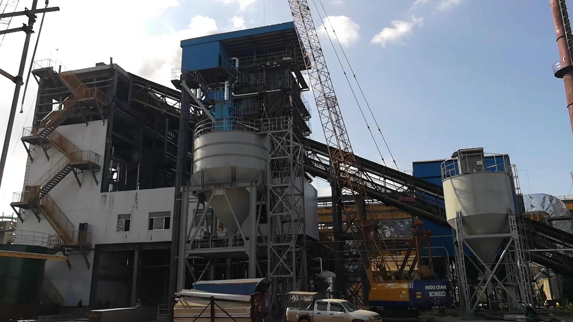
How Does Fuel Type and Availability Affect the Selection of a Power Plant Boiler?

When selecting a boiler for a power plant, most attention often goes to output capacity or thermal efficiency. But one foundational factor dictates nearly every other aspect of the boiler’s design, cost, and long-term viability: the type and availability of fuel. Fuel is the boiler’s lifeblood—and mismatching boiler design to fuel properties can lead to inefficiencies, structural damage, regulatory problems, or unsustainable operational costs. Conversely, aligning boiler specifications with the right fuel and its local availability ensures cost-effective, reliable, and emissions-compliant operation for decades.

Fuel type and availability are critical to power plant boiler selection because they directly determine combustion system design, boiler configuration, emissions control requirements, capital cost, and operational reliability. Different fuels vary in calorific value, moisture, ash content, combustion characteristics, and supply logistics. A boiler must be tailored to handle the specific thermal and physical properties of its intended fuel efficiently and cleanly. Fuel availability also affects long-term cost, plant location feasibility, supply chain risk, and environmental compliance strategies.

Selecting the wrong boiler for the available fuel—or the wrong fuel for the intended boiler—leads to cascading technical and economic failures.

Boilers can efficiently use any type of fuel without changes in design.False

Boilers must be specifically engineered to match the combustion and chemical characteristics of the fuel to operate efficiently and safely.

Fuel availability in the region affects the long-term feasibility of a power plant project.True

Fuel transport and supply logistics influence fuel costs, carbon footprint, and system reliability over the plant’s lifecycle.

🔍 The Thermodynamic and Economic Role of Fuel in Boiler Selection

Every power boiler is designed to convert chemical energy into steam, but each fuel releases energy in different ways. Critical fuel parameters include:

Fuel CharacteristicImpact on Boiler Design
Calorific Value (kcal/kg)Determines combustion chamber size and heat rate
Ash Content & Fusion TempAffects slagging, fouling, and soot blower design
Volatile MatterInfluences ignition and flame control
Moisture ContentIncreases flue gas volume, reduces efficiency
Sulfur/Chloride ContentTriggers corrosion; dictates emissions controls (e.g., scrubbers)
Particle SizeAffects burner, stoker, or feeder design

Fuel affects not only the boiler internals but also the entire balance-of-plant system—from handling to emissions.


📊 Comparison of Fuels Used in Power Plant Boilers

Fuel TypeTypical CV (kcal/kg)Ash Content (%)Moisture (%)Boiler Type Compatibility
Bituminous Coal5,800–6,80010–155–12Pulverized Coal (PC), Fluidized Bed
Sub-bituminous4,200–5,50010–2510–20CFBC, Stoker, Hybrid
Biomass2,500–4,5001–515–50Grate, CFBC, Gasifier-Boiler Hybrid
Natural Gas8,500–9,50000Package, HRSG, Once-Through
Fuel Oil9,000–10,000<0.10Package, Water Tube, Multi-fuel
Lignite2,000–3,50015–2530–60CFBC, Specialized Lignite Boilers
RDF (Waste)1,800–3,00010–2015–35Waste-to-Energy, CFBC

🧪 Case Study: Biomass vs. Coal in a 30 MW Plant

Scenario: Evaluating boiler selection for a renewable transition project
Location: Rural Southeast Asia
Fuel Options: Rice husk biomass (local) vs. imported coal

MetricBiomass (Rice Husk)Coal (Bituminous)
Calorific Value (kcal/kg)3,0006,200
Boiler Efficiency (%)82%88%
Fuel Cost ($/ton)18120
Fuel AvailabilityAbundant (local)Imported (port + truck)
CO₂ Emissions (tons/MWh)~0 (biogenic)1.0–1.2
CapEx (Boiler + Emission System)Higher (slagging mgmt.)Moderate

Result: Biomass CFBC boiler selected due to fuel availability, cost stability, and carbon neutrality despite lower efficiency.


🔧 How Fuel Type Drives Boiler Design Choices

🔸 Coal (High-Rank and Sub-Bituminous)

  • Requires pulverizers, large ash hoppers, air preheaters

  • Boilers are large, with intense slagging/fouling zones

  • Requires electrostatic precipitators (ESPs) and scrubbers

🔸 Biomass

  • Boiler needs large furnace volume (low energy density)

  • Prone to slagging, needs frequent soot blowing

  • Supports carbon-neutral operation, renewable incentives

🔸 Natural Gas

  • Compact, high-efficiency HRSGs or package boilers

  • Minimal ash/emissions → lower O&M

  • Fuel price volatility can be high without long-term contracts

🔸 Waste Fuels / RDF

  • Highly variable → requires robust feeding and combustion flexibility

  • High corrosion potential → advanced material linings


📉 Consequences of Fuel–Boiler Mismatch

Mismatch ScenarioImpact
Low-CV fuel in coal boilerPoor combustion, low output, high unburned carbon
High-ash fuel in PC boilerSlagging, erosion, lower heat transfer efficiency
High-moisture fuel without pre-dryingIncreased flue gas loss, corrosion
Fuel variability without controlsUnstable steam generation, unsafe combustion
Switching fuels post-designRetrofitting costs, emissions non-compliance

⚙️ Best Practices for Fuel-Based Boiler Selection

✅ Conduct fuel analysis (proximate + ultimate) for each candidate fuel
✅ Match CV, ash, sulfur, and moisture properties to combustion system
✅ Use CFD and heat balance modeling to simulate boiler performance
✅ Consider multi-fuel capability if supply uncertainty exists
✅ Integrate fuel handling system with boiler sizing
✅ Factor fuel logistics and contracts into LCOE (Levelized Cost of Energy)
✅ Evaluate emission control needs based on sulfur/nitrogen content
✅ Choose proven technologies for the fuel type in similar climates/applications


📊 Fuel Supply and Logistics: A Hidden Cost Factor

ParameterBiomass (Local)Coal (Imported)
Annual Fuel Cost ($/MWh)18–2540–70
Supply Chain ComplexityLowHigh (rail + port)
Delivery Lead Time1–2 days10–20 days
Regulatory BurdenLowHigh (import license, ash disposal)

Boiler selection should not just consider fuel specs, but also availability, reliability, and cost over decades.


🧩 Fuel Type Selection: Long-Term Impact on Performance

FactorFuel-Driven Influence
Thermal EfficiencyGas > Coal > Biomass > RDF
Carbon FootprintBiomass ≈ 0; Gas moderate; Coal highest
Emissions ComplianceCoal and RDF need more treatment systems
Maintenance FrequencyBiomass and RDF require more cleaning
Boiler Life ExpectancyHigher with cleaner fuels and stable combustion

Fuel type is the starting point of boiler selection—it determines everything from thermodynamics to environmental strategy. By choosing the right boiler for the available fuel, power plant operators ensure reliability, efficiency, and long-term cost control.

What Role Does Thermal Efficiency Play in Choosing the Right Power Plant Boiler?

Choosing the right boiler for a power plant isn’t just a matter of size or fuel—it’s a question of how effectively the system can convert fuel into usable energy. That’s where thermal efficiency becomes a defining parameter. Thermal efficiency determines the ratio of the fuel’s energy that actually gets converted into steam—and, ultimately, into electricity. Poor thermal efficiency results in fuel waste, higher emissions, larger environmental footprints, and excessive operational costs. When selecting a boiler, understanding and prioritizing thermal efficiency ensures optimal performance, fuel economy, and regulatory compliance across the plant’s lifespan.

Thermal efficiency plays a pivotal role in power plant boiler selection because it measures how effectively the boiler converts the chemical energy in fuel into usable thermal energy (steam). High-efficiency boilers require less fuel for the same steam output, lowering operational costs, improving carbon performance, and enabling more competitive electricity generation. It influences boiler type, design complexity, heat recovery integration, and fuel compatibility. Plants aiming for long-term sustainability and profitability must select boilers with high thermal efficiency aligned to their fuel and load profile.

Put simply, a boiler’s thermal efficiency determines the power plant’s fuel bill, emissions rate, and profitability—choosing the wrong efficiency level compromises all three.

Thermal efficiency determines how much of the fuel's energy is converted into usable steam.True

Thermal efficiency is the ratio of energy output (steam) to energy input (fuel) and directly impacts performance and operating costs.

All boiler systems operate at similar thermal efficiencies regardless of design.False

Boiler efficiencies vary significantly depending on design, fuel, heat recovery systems, and control mechanisms.


🔍 What Is Thermal Efficiency in a Power Plant Boiler?

Thermal efficiency is calculated using the formula:

η = (Heat Output as Steam / Heat Input from Fuel) × 100

It depends on:

  • Fuel combustion efficiency

  • Heat transfer rate

  • Flue gas losses

  • Radiation and convection losses

  • Blowdown and scale losses

Efficiency MetricTypical Value RangeExplanation
Combustion Efficiency95–99%Based on complete burning of fuel
Boiler Thermal Efficiency75–92%Real-world total conversion efficiency
Gross vs. Net EfficiencyGross = includes latent heat; Net = excludes it 

Higher thermal efficiency means less fuel is needed per unit of steam—which directly reduces operating costs and emissions.


📊 Thermal Efficiency by Boiler Type and Design

Boiler TypeTypical Thermal Efficiency (%)Best Use Case
Fire-tube Boiler70–78Small-scale applications, lower pressure
Water-tube Boiler82–88Medium- to large-scale industrial plants
Pulverized Coal Boiler (PC)84–90High-efficiency baseload generation
Circulating Fluidized Bed (CFBC)80–86Fuel flexibility, lower emissions
Natural Gas HRSG90–95Combined cycle power plants
Supercritical Boiler91–93Utility-scale high-efficiency operations

⚙️ Why Efficiency Should Be Central to Boiler Selection

Key AreaEfficiency Influence
Fuel ConsumptionHigher efficiency = lower fuel per MWh
Operating CostFuel cost typically makes up 60–70% of OPEX
Emissions ProfileLower fuel burn = reduced CO₂, SO₂, NOₓ
Boiler Size & WeightEfficient boilers require less volume for same output
Water Treatment NeedsEfficient heat use reduces blowdown and makeup water
Turbine CompatibilityHigh-efficiency boilers produce better steam quality

Example: A 1% increase in thermal efficiency can reduce fuel usage by 1.5–2%, saving thousands of tons of fuel annually in a 100 MW plant.


🧪 Case Study: Efficiency Impact on Cost and Emissions

Scenario: Selecting a boiler for a 100 MW coal-fired plant

Efficiency Level85% Efficient91% Efficient
Annual Fuel Use (tons)200,000187,000
Fuel Cost ($/ton)$100$100
Annual Fuel Cost ($)$20,000,000$18,700,000
CO₂ Emissions (tons/year)540,000504,000
Payback on High-Eff Boiler~2.4 years

Even modest efficiency gains can deliver six-figure savings annually with significant environmental benefits.


🔧 Design Features That Improve Thermal Efficiency

FeatureFunctionEfficiency Gain
EconomizerRecovers heat from flue gas to preheat feedwater+4–7%
Air Preheater (APH)Warms combustion air using exit flue gas+2–5%
Superheater & ReheaterIncreases steam temperature for better turbine efficiency+3–5%
Condensate RecoveryReduces makeup water and latent heat losses+1–2%
Low Excess Air ControlMinimizes flue losses without increasing CO+1–3%

Integrating these systems into the boiler design ensures high baseline efficiency and scalability.


📉 Risks of Choosing a Low-Efficiency Boiler

ConsequenceImpact
Increased Fuel Cost5–10% more fuel needed per MWh
Higher EmissionsCarbon taxes, regulatory penalties
Poor Load FlexibilityEfficiency drops sharply at part-load
Shorter Boiler LifeHigher internal stress from inconsistent combustion
Uncompetitive LCOEHigher power price vs. peers

📈 Efficiency Across Load Conditions

Load LevelHigh-Efficiency BoilerLow-Efficiency Boiler
100% (Full Load)91–92%84–86%
75%89–90%80–83%
50%87–88%75–78%
<30% (Low Load)82–84%70–75%

High-efficiency boilers maintain better performance at lower loads—critical for modern, variable-demand grids.


🧩 Thermal Efficiency Selection Checklist

✅ Identify fuel CV and combustion behavior
✅ Determine steam output and quality requirements
✅ Choose boiler type that balances efficiency vs. cost
✅ Integrate economizer, APH, and superheaters
✅ Analyze part-load efficiency profile
✅ Model total LCOE (Levelized Cost of Electricity)
✅ Prioritize emission reduction incentives or carbon limits
✅ Plan for long-term fuel cost fluctuation


🌍 Environmental and Regulatory Impacts

Regulation/Impact AreaThermal Efficiency Influence
CO₂ Emission CapsLower emissions per MWh = easier compliance
Carbon Tax/TradingReduced exposure to cost fluctuations
ESG and SustainabilityHigher efficiency = lower carbon intensity
Water Use and BlowdownReduced losses with improved heat transfer

Choosing an efficient boiler isn’t just good engineering—it’s good governance and climate-smart economics.


Thermal efficiency is the defining metric of boiler performance. It governs fuel use, emissions, cost, and capacity planning. A boiler with higher thermal efficiency provides better returns, lower environmental impact, and stronger operational reliability—making it an essential selection criterion in any modern power plant project.
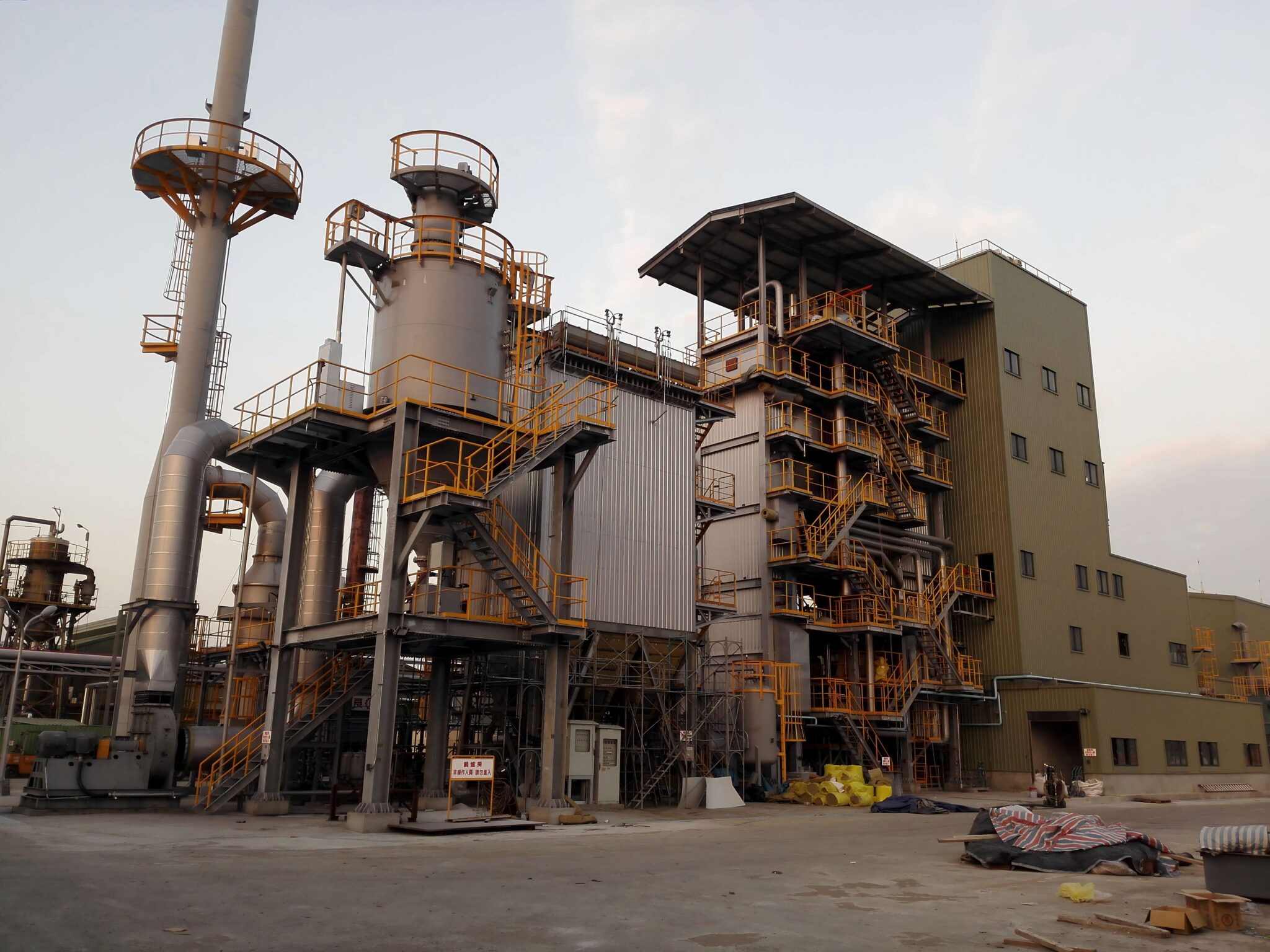
How Do Emission Regulations and Environmental Standards Shape Boiler Selection?

In the modern energy and manufacturing landscape, power generation is no longer evaluated by output alone. Growing global pressure to reduce air pollution and combat climate change means power plants must comply with strict emission regulations—from national policies like the U.S. Clean Air Act and EU Industrial Emissions Directive to international protocols like the Paris Agreement. These environmental standards directly impact how boilers are selected, especially in terms of fuel compatibility, combustion design, emission control systems, and long-term sustainability. Failing to align boiler design with these regulations can result in non-compliance, heavy penalties, plant shutdowns, or even legal consequences.

Emission regulations and environmental standards critically shape boiler selection by requiring technologies and designs that minimize harmful emissions such as nitrogen oxides (NOₓ), sulfur oxides (SO₂), particulate matter (PM), and carbon dioxide (CO₂). These regulations influence the choice of fuel, combustion method, boiler type, and pollution control systems. Modern boiler selection must incorporate design features like low-NOₓ burners, flue gas desulfurization, bag filters or ESPs, and efficiency enhancements to meet both current and anticipated environmental limits. Compliance ensures operational legality, reduced environmental impact, and eligibility for green financing and carbon incentives.

Emission standards are no longer optional guidelines—they are legally binding benchmarks that every new or retrofitted boiler must meet from day one.

Power plant boilers must comply with specific emission standards for pollutants like NOx, SO2, and CO2.True

Emission regulations require all new and operating boilers to stay within defined pollutant limits, which influence boiler design, fuel choice, and control systems.

Environmental regulations are optional considerations during boiler selection.False

Compliance with environmental laws is mandatory and shapes both boiler selection and project feasibility. Non-compliance can lead to severe financial and legal penalties.


🔍 Which Emissions Are Regulated—and How?

PollutantSourceEnvironmental ImpactTypical Control Methods
NOₓ (Nitrogen Oxides)High-temperature combustionSmog formation, acid rain, respiratory issuesLow-NOₓ burners, SNCR, SCR
SO₂ (Sulfur Dioxide)Sulfur in fuel (esp. coal, oil)Acid rain, aquatic ecosystem damageLimestone injection, FGD (wet/dry scrubbers)
PM (Particulate Matter)Ash, soot, fly ash in flue gasLung disease, visibility reductionESPs, baghouses, cyclones
CO (Carbon Monoxide)Incomplete combustionToxic gas, combustion inefficiency indicatorCombustion tuning, O₂ control
CO₂ (Carbon Dioxide)Combustion of any fossil fuelGreenhouse gas, climate change driverFuel switching, efficiency improvement, CCS
VOC & Hg (Volatiles, Mercury)Minor fuel contaminantsToxicity, bioaccumulationActivated carbon injection, fuel pre-treatment

📊 Global Emission Standards Comparison

Region/StandardNOₓ (mg/Nm³)SO₂ (mg/Nm³)PM (mg/Nm³)Notes
U.S. EPA (New Source)90–180130–20010–30Varies by plant type and fuel
EU Industrial Directive15020020For large combustion plants (>50 MW)
India CPCB II30010030Tightened in recent years for coal plants
China GB 13223-201110010030Among strictest for coal-fired units

Designing boilers to meet future tightening of these limits is increasingly vital.


🧪 Case Study: Emission-Limited Boiler Selection in a 120 MW Plant

Scenario: New power plant project in Europe with tight EU-IED limits
Fuel Options: Bituminous coal vs. biomass blend
Emission Targets:

  • NOₓ ≤ 150 mg/Nm³

  • SO₂ ≤ 200 mg/Nm³

  • PM ≤ 20 mg/Nm³

Boiler TypeEmissions Before ControlRequired Control SystemsFinal Selection?
Pulverized Coal (PC)NOₓ: 350, SO₂: 400, PM: 80SCR + FGD + ESP❌ Too costly to retrofit
Circulating Fluidized Bed (CFBC)NOₓ: 120, SO₂: 90, PM: 25Baghouse + limestone bed✅ Efficient compliance
Biomass Stoker BoilerNOₓ: 180, SO₂: negligible, PM: 35SNCR + baghouse❌ Borderline NOₓ level

Outcome: CFBC selected due to inherent low emissions and better regulatory alignment.


🔧 How Emission Rules Affect Boiler Design Choices

🔸 1. Fuel Type Compatibility

  • High-sulfur coal → more costly SO₂ control

  • Biomass → cleaner but needs PM filtration

  • Gas → low NOₓ and SO₂; easier to meet limits

🔸 2. Combustion System Design

Boiler TypeNatural NOₓ/SO₂ OutputEmission Control Cost
PC BoilerHighHigh
CFBC BoilerMedium (self-limiting)Medium
HRSG (Gas)LowLow

🔸 3. Heat Recovery and Efficiency Focus

  • Economizers reduce CO₂ intensity

  • Lower stack temperatures → less fuel = less emissions


⚙️ Required Emission Control Technologies by Fuel

Fuel TypeCommon Controls Required
CoalSCR/SNCR, FGD, ESP or baghouse, mercury controls
BiomassBaghouse or ESP, SNCR for NOₓ
Natural GasLow-NOₓ burner, optional SCR
Waste/RDFBaghouse + activated carbon + multi-pollutant control

Boilers must have space, access, and configuration to integrate these technologies without performance loss.


📉 Risks of Ignoring Emission Regulations in Boiler Selection

ConsequenceImpact
Non-compliance fines$100,000+ per violation (varies by region)
Operating license revokedPlant shutdown, reputational loss
Increased retrofitting costs15–40% more expensive than initial integration
Higher LCOEEmissions-related costs raise levelized energy cost
Environmental liabilityLegal action from communities or regulators

📈 Best Practices for Emission-Compliant Boiler Selection

✅ Understand current and future emission limits in the plant’s location
✅ Evaluate fuel quality and emissions profile via lab analysis
✅ Select boiler types with inherently low emissions where possible
✅ Design for modular integration of emission control systems
✅ Conduct CFD and combustion simulation to reduce NOₓ formation
✅ Incorporate real-time emission monitoring (CEMS) into design
✅ Seek green certification or tax credits by exceeding base standards


🌍 Long-Term Benefits of Emission-Driven Boiler Design

CategoryEmission-Compliant Boiler Advantage
Fuel CostLower with high-efficiency + low excess air
Carbon PenaltiesAvoided or reduced with compliant CO₂ performance
Community ApprovalEasier with clean air, transparent data
Sustainability GoalsSupports ESG, net-zero, and carbon offset goals
Operating StabilityFewer shutdowns or deratings for non-compliance

Emission-friendly boiler designs also qualify for green financing, carbon credits, and public-private project funding.


Environmental regulations have transformed boiler selection into an environmental engineering decision. The most successful power projects are those that integrate emissions compliance from the very first design meeting, ensuring the boiler is not only efficient—but also legal, sustainable, and future-ready.
Why Is Operational Flexibility Important in Modern Power Plant Boiler Systems?

In an era defined by fluctuating electricity demand, rising renewable energy integration, fuel price volatility, and tightening emission regulations, power plants are under constant pressure to respond quickly and efficiently. One key capability has emerged as indispensable: operational flexibility. It refers to a boiler system’s ability to adjust output quickly and reliably in response to load changes, grid fluctuations, and fuel variations—without sacrificing efficiency or exceeding emission limits. Inflexible boiler systems are increasingly obsolete in today’s dynamic energy ecosystem.

Operational flexibility is crucial in modern power plant boiler systems because it enables rapid, efficient, and safe adaptation to fluctuating power demands, intermittent renewable energy integration, variable fuel quality, and regulatory requirements. Flexible boilers can ramp up or down quickly, maintain thermal efficiency across a wider load range, tolerate fuel switching, and comply with emissions standards during dynamic operation. This ensures grid stability, economic performance, and long-term system viability in an increasingly volatile energy landscape.

Boilers that can’t adapt fast enough risk becoming stranded assets in a market that now favors agility, responsiveness, and multi-fuel resilience.

Flexible boiler systems are essential to support renewable energy sources in the grid.True

Because renewables like solar and wind are intermittent, flexible boilers help maintain grid balance by quickly adjusting power output.

Operational flexibility only matters in small industrial boilers.False

Flexibility is critical in all boiler systems, especially large-scale utility boilers that must respond to grid demand variations and regulatory pressures.


🔍 What Is Operational Flexibility in a Boiler?

Aspect of FlexibilityDefinition
Load-Following CapabilityBoiler’s ability to vary output based on real-time demand
Ramp RateSpeed of increase/decrease in steam output (tons/min)
Turn-Down RatioRatio of maximum to minimum stable output
Startup/Shutdown TimeTime required to reach full load from cold or warm state
Fuel FlexibilityAbility to operate on more than one type/grade of fuel

Modern boilers must perform optimally across a wide operating envelope without losing combustion efficiency or violating emission standards.


📊 Key Flexibility Metrics for Boiler Performance

MetricStandard BoilerFlexible BoilerImpact
Ramp Rate (tons/hr/min)2–35–10+Faster load response
Turn-Down Ratio3:15:1 to 10:1Broader load range capability
Cold Start Time (hours)8–123–6Faster grid readiness
Minimum Stable Load (%)50%20–30%Supports low-load operations
Fuel AdaptabilityFixedMulti-fuel capableSwitches based on cost/supply

🧪 Case Study: Grid Flexibility in a 500 MW Coal-Fired Plant

Challenge: Grid operator required fast ramping due to high solar penetration
Original Setup: Pulverized coal boiler, 3:1 turn-down, 4 tons/min ramp
Modification: Added VFD fans, AI-based combustion controls, steam bypass

Performance MetricBeforeAfter RetrofitImprovement
Minimum Load (%)50%25%+25% flexibility
Ramp Rate (tons/min)3.87.5+97% response
Efficiency at 60% Load (%)80.285.5+6.6%
Annual Grid Support Events2478+225% reliability

The flexible upgrade allowed this plant to remain competitive and compliant in a renewables-heavy market.


🔧 Key Design Features that Enable Operational Flexibility

Design ElementFunction in Flexible Operation
Advanced Combustion ControlsReal-time tuning of air/fuel ratios for stable combustion
Variable Speed Drives (VFDs)Dynamic control of fans and pumps to match load
Once-Through Boiler DesignEliminates drum constraints; ideal for fast startup/shutdown
Steam Bypass SystemsPrevent turbine overspeed during ramping
Modular Burner ConfigurationAllows sectional burner firing for low-load stability
Thermal Storage / AccumulatorsAbsorbs steam during oversupply, releases during demand

These elements must be integrated during boiler design—retrofitting later can be costly and limited.


⚙️ How Flexibility Supports Key Energy Trends

Energy TrendFlexibility Benefit
Renewable IntegrationCompensates for solar/wind intermittency
Carbon PricingEnables fuel switching or optimized low-carbon operation
Distributed GenerationResponds to local demand spikes or drops
Energy Trading/Ancillary ServicesParticipates in frequency response and spinning reserve markets
Seasonal/Hourly Demand FluctuationsMaintains high efficiency at partial loads

📉 Risks of Inflexible Boiler Operation

ProblemConsequence
Poor Low-Load PerformanceHigh unburned carbon, emissions spikes, combustion failure
Slow Ramp-UpMissed peak demand, grid penalties
Frequent ShutdownsThermal stress, tube damage, startup fuel waste
Fuel Lock-InEconomic losses if primary fuel becomes costly or banned
Non-Compliance with Grid CodesFines or market exclusion

📈 Best Practices for Ensuring Operational Flexibility

✅ Specify high turn-down ratio burners during design
✅ Integrate multi-mode combustion controls (manual, auto, AI-driven)
✅ Ensure turbine-boiler coordination logic for seamless load-following
✅ Include advanced instrumentation and diagnostics
✅ Use real-time data analytics to anticipate load changes
✅ Design with multi-fuel capability where feasible
✅ Maintain a flexibility scorecard tied to performance KPIs


🌍 Environmental & Economic Benefits of Flexible Boilers

Benefit AreaImpact from High Flexibility
Efficiency at Part Load4–8% higher than standard boilers
Emissions ComplianceFewer exceedances during ramping or low-load
Fuel OptimizationAbility to switch to cheaper/cleaner fuels
System AvailabilityFewer trips, faster recovery = >97% uptime
Revenue OpportunitiesAncillary grid services, carbon credit eligibility

Flexible boilers deliver not just technical superiority—but also strategic and financial resilience.


Operational flexibility is no longer a luxury—it is a strategic necessity. As grids decarbonize, regulations tighten, and energy prices fluctuate, boilers must not only produce steam, but also respond, adapt, and perform under a wide range of conditions. Boiler systems designed with flexibility in mind will define the next generation of clean, competitive, and intelligent power plants.

🔍 Conclusion

Choosing the right boiler involves more than matching output with demand—it requires a strategic approach that balances technical performance with cost-efficiency, fuel logistics, and regulatory compliance. Each parameter plays a vital role in long-term reliability and success.⚡🌱✅

FAQ

Q1: What are the most important technical parameters when selecting a power plant boiler?
A1: Key technical parameters include steam pressure, temperature, and capacity. High-pressure, high-temperature boilers enable better thermal efficiency and higher power output. Capacity determines the amount of steam the boiler can generate, directly impacting power plant performance. Selecting the right pressure-temperature combination ensures efficient operation and longer service life under demanding industrial conditions.

Q2: How does fuel type influence boiler selection for power plants?
A2: The choice of fuel—coal, natural gas, biomass, or oil—directly affects boiler design, combustion system, and emissions control. For instance, coal-fired boilers require slag handling and emissions filtering, while natural gas systems are cleaner and more compact. Availability, cost, and environmental regulations also play a role. Selecting a boiler compatible with your fuel type ensures optimized combustion and reduced environmental impact.

Q3: Why is boiler efficiency a crucial selection factor?
A3: Boiler efficiency determines how well the boiler converts fuel into usable energy. High-efficiency boilers reduce fuel consumption, lower operating costs, and minimize emissions. Factors such as heat recovery systems, insulation, and burner performance influence overall efficiency. A high-efficiency boiler is essential for sustainable and cost-effective power generation.

Q4: What role does load demand play in choosing a power plant boiler?
A4: Load demand influences the required boiler size and its ability to handle base and peak loads. Boilers should be matched to the plant’s average and peak load requirements to avoid inefficiencies from under or over-sizing. Some plants may require multiple boilers or modulating capacity to meet variable load conditions without sacrificing performance.

Q5: How do environmental and regulatory standards affect boiler selection?
A5: Power plant boilers must comply with local and international environmental regulations, including limits on NOx, SOx, CO2, and particulate emissions. Compliance often dictates the inclusion of pollution control equipment such as scrubbers, selective catalytic reduction (SCR), and electrostatic precipitators. Selecting a boiler that meets these standards is essential to avoid penalties and ensure sustainable operations.

References

  1. Boiler Selection Considerations – https://www.cleaverbrooks.com/reference-center/boiler-selection-guide.aspx – Cleaver-Brooks

  2. Power Plant Boiler Efficiency – https://www.energy.gov/eere/amo/boiler-systems-efficiency – U.S. Department of Energy

  3. Fuel Choices for Boilers – https://www.eia.gov/energyexplained/biomass/biomass-and-the-environment.php – U.S. Energy Information Administration

  4. Emissions Compliance for Boilers – https://www.epa.gov/stationary-sources-air-pollution – U.S. Environmental Protection Agency

  5. Boiler Design Parameters – https://www.sciencedirect.com/topics/engineering/boiler-design – ScienceDirect

  6. Industrial Steam Boiler Load Management – https://www.tlv.com/global/TI/steam-theory/load-matching.html – TLV Corporation

  7. Steam Boiler Pressure and Temperature – https://www.engineeringtoolbox.com/boiler-steam-capacity-d_1111.html – The Engineering Toolbox

  8. Combustion Systems for Power Boilers – https://www.babcock.com/home/products/boilers/ – Babcock & Wilcox

  9. Power Generation Standards and Compliance – https://www.iso.org/standard/66580.html – International Organization for Standardization (ISO)

  10. Energy Efficiency in Power Plants – https://www.iea.org/topics/power – International Energy Agency

Wade Zhang

CEO of Taishan Group Taian Boao International Trade Co., Ltd. 30 years experience in Global industrial boiler market,  Over 300 boiler projects experience, including 21+ EPC projects. Projects span 30+ countries & regions, involving industries such as nuclear power, energy & electricity, municipal heating, mining, textiles, tires etc.

What Are the Essential Parameters for Selecting a Power Plant Boiler? Read More »
Top 5 Key Factors Affecting Coal-Fired Boiler Efficiency

Top 5 Key Factors Affecting Coal-Fired Boiler Efficiency

Coal-fired boilers remain a mainstay in many industrial sectors due to their high energy output and cost-effectiveness. However, operating these boilers efficiently is a growing concern, especially with increasing energy costs and stricter environmental regulations. Poor efficiency not only drives up fuel consumption and emissions but also leads to higher maintenance costs and reduced equipment lifespan. The good news? Several controllable factors directly influence how well a coal-fired boiler performs.

The top 5 key factors affecting industrial coal-fired boiler efficiency are: coal quality and preparation, combustion air control, boiler design and heat transfer surface area, soot blowing and slagging control, and load variation management. Optimizing these elements leads to higher thermal efficiency, reduced emissions, and lower operational costs.

Understanding these key factors is essential for plant managers, engineers, and maintenance teams looking to reduce fuel waste and increase boiler performance. Let’s explore each aspect in detail to help you make data-driven improvements.

How Does Coal Quality and Preparation Affect Coal-Fired Boiler Efficiency?

Coal-fired boilers remain a dominant force in power generation and industrial steam production, particularly in regions where coal is economically favorable. However, coal is not a uniform fuel. Variations in its chemical composition, moisture, ash content, and size can significantly alter combustion characteristics, heat output, slagging behavior, and emissions—ultimately affecting overall boiler efficiency. Many operational inefficiencies and excessive maintenance issues in coal-fired plants stem from poor coal quality or inadequate coal preparation.

Coal quality and preparation directly affect the efficiency of coal-fired boilers by influencing combustion completeness, heat transfer, slagging and fouling rates, and the calorific value delivered per unit mass. High-moisture or high-ash coal requires more energy to burn and produces more waste, while improperly sized coal reduces combustion uniformity. Proper preparation—such as washing, drying, sizing, and blending—ensures more stable combustion, better heat rate, and lower emissions, resulting in improved thermal efficiency and boiler reliability.

Even with advanced boiler technology, if the coal fuel input is subpar, system performance will degrade. That’s why understanding the nuances of coal quality and preparation is critical to optimizing efficiency and reducing operating costs.

All types of coal burn equally well in coal-fired boilers.False

Different coal grades have varying calorific values, moisture, ash content, and combustion behavior, which greatly impact efficiency and performance.

Improved coal preparation reduces slagging and enhances boiler efficiency.True

Removing impurities and optimizing particle size improves combustion uniformity, reduces unburned carbon, and minimizes deposits on heat transfer surfaces.

🔍 Key Coal Properties That Affect Boiler Efficiency

PropertyImpact on Boiler Efficiency
Calorific Value (CV)Determines how much energy is released per unit of coal
Moisture ContentHigh moisture absorbs heat during evaporation, reducing net thermal output
Ash ContentInert material that doesn’t combust, contributes to slagging and heat transfer loss
Volatile MatterAffects ignition temperature, flame stability, and combustion speed
Fixed CarbonMain contributor to sustained combustion
Sulfur ContentInfluences SO₂ emissions and corrosion risks
Grindability (HGI)Impacts how easily coal can be pulverized for proper burner feeding
Particle SizeToo coarse → incomplete combustion; Too fine → handling issues and increased PM emissions

📊 Comparative Efficiency Based on Coal Grades

Coal TypeCalorific Value (MJ/kg)Moisture (%)Ash (%)Typical Boiler Efficiency (%)
Anthracite28–332–58–1285–88
Bituminous Coal24–305–1510–1580–86
Sub-Bituminous Coal18–2415–2515–2075–82
Lignite (Brown Coal)10–1830–5020–2565–75

Coal-fired boilers must be designed or adapted to the type of coal they burn. Burning a low-rank coal in a system designed for high-rank fuel leads to efficiency losses, slagging, and excessive wear.


🔧 How Coal Preparation Enhances Boiler Efficiency

Coal preparation involves various processes to improve the consistency and quality of the fuel before combustion:

🔹 1. Coal Washing

  • Removes rock, soil, and sulfur compounds

  • Reduces ash content by up to 10–15%

  • Enhances CV and reduces SO₂ emissions

🔹 2. Drying and Moisture Reduction

  • Lignite and sub-bituminous coals benefit greatly

  • Every 1% moisture reduction increases efficiency by 0.8–1%

  • Methods: thermal drying, hot air, or waste heat recovery

🔹 3. Sizing and Pulverization

  • Ensures uniform particle size for complete combustion

  • Ideal particle size: 70–80% passing through 200 mesh

  • Reduces unburned carbon losses

🔹 4. Blending Coals

  • Mixes high-CV and low-CV coals to stabilize combustion

  • Reduces slagging and enhances flame temperature consistency


📉 Efficiency Loss from Poor Coal Quality

Coal ConditionEfficiency Impact
High moisture (>25%)-5% to -12%
High ash (>20%)-4% to -10%
Oversized particles (>10 mm)Incomplete combustion, >5% fuel waste
High sulfur (>3%)Corrosion, extra flue gas treatment needed
Variable CV in mixed batchesFlame instability, inconsistent heat rate

🔥 Combustion Stability and Slagging Behavior

Slagging (molten ash deposits on heat surfaces) drastically reduces heat transfer and leads to costly shutdowns.

FactorEffect on Slagging
Ash Fusion TemperatureLower fusion temp = higher slagging risk
Mineral CompositionSodium and iron increase slag potential
Combustion TemperatureHigh furnace temp exacerbates slag formation
Coal SizingUniform size reduces local hot spots

Solution: Use low-ash, high-fusion point coals and proper burner design to mitigate slag risk.


🧪 Case Study: Efficiency Boost via Coal Blending and Drying

Industry: Cement manufacturing
Boiler: 40 TPH pulverized coal-fired boiler
Coal Used: Initially raw lignite (38% moisture)
Intervention:

  • Installed coal dryer using flue gas

  • Blended 30% sub-bituminous coal with lignite

  • Added size classifier for uniformity

MetricBeforeAfterImprovement
Boiler Efficiency (%)7281+9%
Moisture Content (%)3820-18%
Steam Output (TPH)3842+4 TPH
Ash Handling Cost (Monthly)$11,000$7,400-33%

🛠️ Best Practices for Managing Coal Quality in Boilers

  1. Install coal analyzers for CV, ash, and sulfur content monitoring

  2. Implement coal sampling and lab testing at delivery points

  3. Use pulverizers with adjustable grinding settings

  4. Apply smart feeder systems to regulate coal flow rates

  5. Maintain air-fuel ratio tuning based on coal properties

  6. Clean burners and heat surfaces regularly to remove slag and fouling

  7. Use computational fluid dynamics (CFD) for combustion optimization


🌍 Environmental and Economic Implications

Impact AreaPoor Coal QualityOptimized Coal Quality
Fuel EfficiencyHigher fuel use for same outputLower fuel cost per ton of steam
Emissions (SO₂, NOₓ)More pollutants, harder to controlEasier emissions compliance
Boiler LifeIncreased wear, slagging, corrosionLonger life, fewer shutdowns
Maintenance CostsFrequent tube cleaning, repairsReduced maintenance intervals

Coal quality and preparation are critical levers for driving the efficiency, cost, and environmental performance of coal-fired boilers. Plants that invest in coal treatment, size control, moisture reduction, and blending routinely outperform those that treat coal as a “fixed” input. Even slight improvements in coal characteristics can yield major returns in fuel savings and boiler longevity.

Why Is Combustion Air Control Critical for Improving Coal-Fired Boiler Performance?

Coal-fired boilers are complex thermal systems where fuel quality, combustion conditions, and heat transfer must align perfectly to achieve maximum efficiency. Among the many variables that influence boiler performance, combustion air control stands out as one of the most impactful. Air is required to oxidize the coal’s carbon content during combustion, but too much or too little air can drastically reduce efficiency, increase emissions, and damage equipment. Intelligent air control ensures stable flames, full fuel burn, and optimal heat recovery—making it a cornerstone of high-performance coal boiler operation.

Combustion air control is critical for improving coal-fired boiler performance because it directly affects combustion efficiency, heat transfer, emissions, and fuel consumption. Properly balanced primary and secondary airflows ensure complete fuel burnout, minimize unburned carbon losses, reduce excess air heat losses, and optimize flame temperature. Poor air control leads to incomplete combustion, high CO and NOₓ emissions, reduced steam output, and increased slagging. Advanced air control systems with real-time oxygen trim and airflow modulation significantly enhance boiler stability and thermal performance.

Effective air management isn’t optional—it’s fundamental to maximizing fuel value and ensuring environmental compliance.

Coal-fired boilers operate best with the maximum possible combustion air.False

Excessive air leads to heat loss through the stack, reducing thermal efficiency. The optimal air-to-fuel ratio ensures complete combustion without excess air.

Controlling primary and secondary airflows helps optimize flame shape and reduce emissions.True

Proper air staging stabilizes the flame, reduces localized hot spots, and limits NOₓ formation, improving efficiency and air quality.

🔍 The Role of Combustion Air in Coal-Fired Boilers

In coal combustion, oxygen is essential to react with carbon and hydrogen in the fuel to produce heat. This oxygen is delivered through combustion air, which is usually divided into:

Air TypePurpose
Primary Air (PA)Transports and dries pulverized coal, initiates ignition
Secondary Air (SA)Supports full combustion, controls flame shape and turbulence
Tertiary Air (TA)Sometimes used to reduce NOₓ or support staged combustion

🔥 Ideal Air-to-Fuel Ratios

To fully combust 1 kg of coal:

  • Theoretically required air: ~10–12 kg of air

  • Real-world systems require: 15–20% excess air

Fuel TypeStoichiometric Air (kg/kg fuel)Recommended Excess Air (%)
Bituminous Coal~10.515–20%
Sub-Bituminous~9.020–25%
Lignite~8.525–30%

Too little air → incomplete combustion, CO, smoke
Too much air → excess heat loss, lower flame temperature


📉 Impact of Poor Air Control on Boiler Efficiency

Air Control IssueEffect
Excess AirCarries heat out of stack → up to 10% efficiency loss
Insufficient AirIncomplete combustion → high CO and unburned carbon
Unbalanced AirflowFlame instability, tube damage, uneven heat distribution
Delayed Air AdjustmentInefficient load response, steam pressure swings

🔎 Efficiency and Emissions by Excess Air Levels

Excess Air (%)Efficiency ImpactCO EmissionsNOₓ Formation
<5%Flame instabilityHighLow
15–20%Optimal zoneLowControlled
>30%Heat loss ↑, efficiency ↓LowHigh (due to temp)

⚙️ Technologies for Airflow Measurement and Control

Modern coal-fired boilers use a combination of hardware and digital systems to manage air distribution precisely.

🔹 Key Technologies

SystemFunction
Oxygen Trim Control (OTC)Adjusts secondary air based on flue gas O₂ levels
Dampers and VFD FansRegulate PA/SA flow rates for different loads
Airflow Meters (Venturi, V-cone)Provide real-time air mass flow data
Combustion Optimization SoftwareUses AI/algorithms to tune air-fuel balance dynamically

Benefits of intelligent combustion air control:

  • Fuel savings of 3–7%

  • CO reduction by up to 60%

  • Improved steam pressure stability

  • Fewer tube failures and slagging incidents


🧪 Real-World Case Study: Air Control Optimization

Plant Type: 120 MW Coal Power Station
Problem: High stack temperatures, low efficiency, CO peaks during load changes
Solution:

  • Installed oxygen trim controller

  • Added airflow dampers on SA ducts

  • Calibrated air-fuel ratio control loop

MetricBeforeAfterImprovement
Boiler Efficiency (%)81.586.2+4.7%
Stack Temperature (°C)260220-40°C
CO Emissions (mg/Nm³)17065-62%
Load Response Time6 min3.5 minFaster modulation

🔧 Best Practices for Combustion Air Control

  1. Calibrate oxygen sensors and airflow meters regularly

  2. Monitor flue gas O₂, CO, and temperature continuously

  3. Balance primary and secondary air for each burner zone

  4. Use variable speed drives on FD/PA fans for fine tuning

  5. Implement air preheating to reduce air density and save fuel

  6. Train operators to adjust for changing coal quality

  7. Use AI-powered combustion tuning systems for dynamic response


🌍 Environmental and Operational Benefits

AspectImprovement from Air Control
Fuel Efficiency3–7% savings
CO₂ EmissionsReduced by up to 10%
Unburned Carbon LossesCut by 30–50%
NOₓ ControlUp to 20% reduction via staged combustion
System ReliabilityFewer flameouts, less slagging

Combustion air control is not just a tuning adjustment—it is a strategic performance lever for every coal-fired boiler. With smart airflow management and real-time optimization, plants can extract more energy per ton of coal, cut emissions, and extend boiler service life—unlocking major operational and environmental value.

How Do Boiler Design and Heat Transfer Surface Area Impact Efficiency?

Efficiency is the heartbeat of every industrial boiler system, especially in sectors where steam is a core utility. Many assume that efficiency is dictated solely by the fuel used or the type of burner installed. While these are critical factors, one of the most fundamental drivers of boiler efficiency is the design of the boiler itself—specifically, the heat transfer surface area. The more effectively a boiler can transfer heat from the combustion gases to the water or steam system, the more energy-efficient and cost-effective it becomes. Poor design or inadequate surface area results in wasted heat, increased fuel use, and higher emissions.

Boiler design and heat transfer surface area directly impact efficiency by determining how much heat can be absorbed from combustion gases into water or steam. Larger and more optimized heat transfer surfaces increase thermal exchange, reduce flue gas temperatures, minimize heat loss, and improve overall fuel-to-steam conversion. Modern multi-pass and water-tube designs outperform older configurations by exposing water to more surface area, enabling faster and more complete heat absorption, which boosts boiler thermal efficiency by 5–15%.

Failing to consider the role of surface area in boiler design is a common mistake that leads to avoidable fuel costs and system inefficiencies. Let’s explore exactly how and why this matters.

Increasing the heat transfer surface area of a boiler improves thermal efficiency.True

A larger surface area allows more heat to be transferred from combustion gases to water, reducing exhaust temperatures and improving energy utilization.

All boiler designs have the same heat transfer effectiveness regardless of shape or layout.False

Different designs—such as fire-tube vs. water-tube, or single-pass vs. multi-pass—offer significantly different heat transfer efficiencies.

🔍 The Science Behind Boiler Heat Transfer

Boiler efficiency is largely a function of how effectively it can transfer heat from the flue gases to the working fluid (usually water). This process is governed by:

Heat Transfer ModeRole in Boilers
ConductionHeat moves through metal tubes or plates
ConvectionGases or fluids carry heat across surfaces
RadiationEmitted from the flame to surrounding surfaces

The heat transfer rate is determined by the formula:

Q = U × A × ΔT

Where:

  • Q = Heat transferred

  • U = Overall heat transfer coefficient

  • A = Heat transfer surface area

  • ΔT = Temperature difference between flue gas and fluid

Increasing A (surface area) allows more heat to be absorbed per unit time—raising the boiler’s thermal efficiency.


🧱 Key Boiler Design Factors That Influence Heat Transfer

Design ElementImpact on Heat Transfer Efficiency
Surface Area (ft² or m²)Larger surface = more heat absorbed = higher efficiency
Number of Gas PassesMore passes = more time in contact with tubes = better heat extraction
Tube Size and ArrangementSmaller, denser tubes = greater area per volume
Baffle DesignDirects flue gases for even contact with all surfaces
Water Circulation MethodForced or natural flow affects exposure to heated walls
Boiler GeometryCompact vs. elongated shapes impact residence time and turbulence

📊 Efficiency Comparison by Boiler Design and Surface Area

Boiler TypeTypical Surface Area (m² per TPH)Efficiency (%)
Single-Pass Firetube6–875–80
Three-Pass Firetube10–1382–86
Four-Pass Firetube14–1685–88
Water-Tube Boiler (High Pressure)18–2588–92
Condensing Boiler20–30 (includes economizer area)90–98

The more heat-exchange surface the flue gases encounter before exiting the stack, the more efficient the boiler becomes.


🔥 Example: Multi-Pass Design vs. Single-Pass Design

Scenario: Industrial plant upgrades from single-pass to three-pass firetube boiler.

MetricSingle-PassThree-PassImprovement
Surface Area (m²)813+62%
Stack Temp (°C)260195-65°C
Fuel Use (per TPH steam)1.35 kg1.18 kg-12.5%
Efficiency (%)7887+9%

By exposing water to more flue gas over more surface area, the upgraded boiler achieves higher efficiency at every load level.


📉 Consequences of Inadequate Surface Area

Boilers with insufficient heat transfer area suffer from:

  • High stack temperatures (more heat lost)

  • Incomplete combustion due to poor thermal feedback

  • Increased fuel use to maintain output

  • Short-cycling or pressure instability

  • Lower ROI and higher emissions

A stack temperature >230°C is often a red flag that indicates insufficient surface area or heat recovery design.


🛠️ Heat Transfer Enhancements for Efficiency

🔹 Add Surface Area with Economizers

  • Recover heat from exhaust gases

  • Increase feedwater temperature

  • Reduce stack temperature by 40–100°C

🔹 Use Fin-Tube or Spiral Tube Designs

  • Increase effective heat area per linear meter

  • Improve convective heat transfer coefficients

🔹 Install Heat Exchangers for Blowdown and Condensate

  • Capture heat from discharged water

  • Preheat makeup water, improving overall system efficiency

🔹 Enhance Tube Cleaning and Maintenance

  • Fouling reduces U (heat transfer coefficient)

  • 1 mm soot or scale can reduce efficiency by 2–5%


🧪 Case Study: Heat Transfer Upgrade with Tube Redesign

Plant: Chemical processing unit
Boiler: 15 TPH steam production, 3-pass firetube
Intervention: Retrofitted extended-surface finned tubes + economizer

MetricBeforeAfterImprovement
Surface Area (m²)185250+35%
Stack Temp (°C)245175-70°C
Efficiency (%)84.291.3+7.1%
Fuel Savings (%)11.8%

Payback Period: 1.7 years, with lifetime emissions savings >1,400 tons CO₂/year


🔧 Best Practices to Maximize Boiler Heat Transfer Efficiency

  1. Select boiler design with multiple passes and larger heat surfaces

  2. Size the boiler appropriately for the steam demand to operate at optimal capacity

  3. Use economizers and condensers to extend the effective heat recovery zone

  4. Choose advanced materials (stainless, alloyed steel) for aggressive fuels

  5. Clean waterside and fireside tubes regularly to maintain U-factor

  6. Use computational fluid dynamics (CFD) to model flue gas flow and optimize design

  7. Integrate thermal insulation to reduce shell and radiation losses


Heat transfer surface area is the core design variable that determines how efficiently a boiler operates. Whether selecting a new system or upgrading an existing one, prioritizing optimal surface area, pass design, and clean heat exchange pathways will yield significant efficiency improvements, fuel savings, and emission reductions across any industrial application.

What Role Do Slagging and Soot Blowing Play in Maintaining Coal-Fired Boiler Efficiency?

Coal-fired boilers rely heavily on the continuous and efficient transfer of heat from combustion gases to water and steam through radiant and convective surfaces. However, slagging (molten ash deposits) and soot (carbon-based particulate buildup) are natural byproducts of burning coal—especially lower-grade or high-ash fuels. These deposits accumulate on boiler tubes, drastically reducing heat transfer, blocking flue paths, increasing pressure drops, and raising exhaust temperatures. Left unchecked, they can lead to severe derating of the boiler’s efficiency, increased fuel consumption, and even unplanned shutdowns.

Slagging and soot blowing play a vital role in maintaining coal-fired boiler efficiency by preventing and removing ash and soot deposits that insulate heat transfer surfaces. Slagging reduces radiant heat absorption, while soot buildup impairs convective heat exchange, causing increased flue gas temperatures, reduced steam generation, and higher fuel use. Soot blowing—through steam, air, or acoustic methods—is a critical maintenance operation that restores clean surface conditions, sustains optimal heat transfer, and protects boiler integrity. Regular slag and soot control can improve thermal efficiency by 2–10% and prevent costly operational disruptions.

When it comes to high-efficiency boiler operation, clean surfaces are just as important as clean combustion. Let’s dive into why slagging and soot blowing are crucial to efficiency and how they should be managed.

Soot buildup has minimal impact on the efficiency of coal-fired boilers.False

Even 1 mm of soot can reduce heat transfer efficiency by 5–8%, leading to increased fuel consumption and stack temperature.

Regular soot blowing is essential for maintaining optimal boiler heat transfer and reducing fuel waste.True

Soot blowing removes insulating deposits on boiler tubes, ensuring efficient heat absorption and reducing emissions.

🔍 Understanding Slagging and Fouling in Coal-Fired Boilers

TermDefinition
SlaggingMolten ash deposits on furnace walls and radiant heat surfaces
FoulingSolid, sticky ash and soot deposits in convective sections or flue passages
SootUnburned carbon particles that settle on tubes due to incomplete combustion

Causes of Slagging and Fouling:

  • High ash content in coal

  • Low ash fusion temperature

  • Inconsistent fuel sizing and combustion

  • Inadequate air-fuel ratio

  • High furnace temperatures or poor flame control

📉 Efficiency Loss Due to Slag and Soot

Deposit ThicknessEfficiency Drop (%)Effect on Heat Transfer
0.5 mm2–3Minor loss in convective sections
1 mm5–8Significant rise in flue gas temperature
2 mm+10–12Severe efficiency loss, likely forced outage
Slag LayerVariableCan block radiant heat and deform furnace walls

Slag not only insulates heat exchange areas but also alters furnace geometry, causing flame deflection and incomplete combustion.


🔧 What Is Soot Blowing and How Does It Work?

Soot blowing is the process of removing ash and soot deposits from boiler tube surfaces to restore proper heat transfer. It’s performed during operation (online) or during outages (offline), using:

Type of Soot BlowerMedium UsedTypical LocationUsage Frequency
Steam BlowersHigh-pressure steamFurnace walls, superheaters, economizersDaily to weekly
Compressed Air BlowersDry airConvective sections, low-moisture areasDaily
Water LancesHigh-pressure waterCleaning during shutdownsMaintenance periods
Acoustic CleanersSound wavesNon-invasive areas like hoppersContinuous or periodic

📊 Boiler Efficiency Gains Through Soot Blowing

Before CleaningAfter CleaningImprovement
Stack Temp: 280°CStack Temp: 220°C-60°C
CO₂ Emissions: 820 g/kWhCO₂ Emissions: 740 g/kWh-9.8%
Fuel Use: 1.5 kg/TPHFuel Use: 1.36 kg/TPH-9.3%
Efficiency: 78%Efficiency: 85.5%+7.5%

Note: Soot blowing’s ROI is often realized within weeks due to reduced fuel usage and avoided downtime.


🧪 Case Study: Automated Soot Blowing System Integration

Industry: Pulp and Paper
Boiler Type: 50 TPH pulverized coal-fired boiler
Problem: Rapid fouling in economizer and superheater sections
Solution: Installed intelligent soot blowing system with flue gas temperature feedback

MetricBeforeAfterChange
Soot Blowing FrequencyManual, 2x/dayAutomated, 6x/day+200% coverage
Downtime per quarter (hrs)186-66%
Boiler Efficiency (%)79.286.1+6.9%
Fuel Savings per Year~$68,000ROI in <8 months

⚙️ Best Practices for Slagging and Soot Blowing Management

🔸 Predictive Maintenance & Monitoring

  • Install infrared sensors to detect hot spots caused by slagging

  • Use flue gas analyzers to monitor combustion efficiency and soot rate

  • Analyze ash fusion temperature to adjust soot blowing intervals accordingly

🔸 Soot Blowing Optimization

Optimization MethodBenefit
Flue Temp-Based ControlTriggers cleaning only when efficiency drops
Zone-Specific BlowingReduces wear by targeting fouled sections only
AI-Assisted Blower LogicLearns fouling patterns and minimizes steam/air usage
Intermittent/Sequential BlowingPrevents thermal shock and maximizes tube lifespan

🔸 Slag Prevention via Fuel and Combustion Control

  • Blend coal to reduce ash fusion issues

  • Maintain ideal furnace temperature (1,100–1,250°C)

  • Avoid flame impingement on water walls

  • Apply anti-slag coatings during major outages


📉 Risks of Neglecting Soot and Slag Control

Neglected IssueOperational Impact
Thick Slag LayerTube overheating, warping, boiler shutdown
Soot Build-up in EconomizerHigh stack temp, derated capacity, increased fuel usage
Manual-Only CleaningInconsistent performance, higher manpower costs
Over-Frequent BlowingTube erosion, excess steam/air consumption

Clean heat surfaces are essential for high boiler thermal efficiency—this is not optional maintenance but a performance-critical requirement.


🌍 Environmental & Economic Benefits

AspectWith Soot/Slag Control
Fuel EfficiencyUp to 10% improvement
CO₂ EmissionsReduced by 8–12%
NOₓ EmissionsLowered by better flame control
Tube LongevityIncreased by up to 25%
Maintenance CostsPredictable and minimized

Slagging and soot formation are inevitable in coal-fired boiler operation—but performance losses from them are not. With automated soot blowing, real-time monitoring, and smart fuel management, you can maintain clean heat surfaces, minimize heat loss, and keep your boiler running at peak efficiency year-round.

How Does Load Variation and Operational Stability Influence Coal-Fired Boiler Efficiency?

Coal-fired boilers are traditionally designed for steady, base-load operation, yet many industrial and utility plants today operate under dynamic load conditions due to fluctuating steam demand, grid variability, or fuel limitations. These load variations can significantly disrupt thermal and combustion stability, ultimately lowering efficiency and increasing wear on equipment. Similarly, operational stability, which includes control of steam pressure, temperature, and combustion air, plays a crucial role in maintaining efficient and safe boiler performance.

Load variation and operational stability influence coal-fired boiler efficiency by altering combustion consistency, heat transfer effectiveness, and steam generation control. Frequent load swings cause thermal stress, sub-optimal combustion, and fuel-air imbalance, leading to higher unburned carbon, increased flue gas temperatures, and reduced heat rate. Stable operation enables optimal flame temperature, consistent steam parameters, and efficient burner performance. Boilers operating within their design load range with minimal fluctuations can achieve 5–10% higher efficiency compared to those under erratic load profiles.

Managing boiler load isn’t just about responding to demand—it’s about engineering control, balance, and predictability into the heart of the combustion process.

Coal-fired boilers maintain the same efficiency regardless of load changes.False

Efficiency drops significantly during low or unstable load conditions due to poor combustion, higher heat losses, and inconsistent steam production.

Maintaining stable load and pressure improves the fuel-to-steam conversion ratio in coal boilers.True

Stable operation ensures optimal combustion and heat transfer, leading to better thermal efficiency and fewer losses.

🔍 The Science Behind Load Variation and Boiler Efficiency

Load ConditionDefinition
Base LoadBoiler runs near design capacity (>85%) consistently
Part LoadLoad reduced to 50–85% of capacity
Low Load/IdleLoad <50%; boiler often cycles on/off or operates inefficiently
Load SwingRapid increases or decreases in demand

Efficiency is highest at 75–90% load for most coal-fired boilers. Outside this range, the system encounters:

  • Combustion imbalance

  • Increased flue gas losses

  • Unburned carbon

  • Reduced steam quality

  • Thermal stress and wear


📊 Efficiency Across Different Load Levels

Operating Load (%)Typical Efficiency (%)Fuel Consumption per TPHFlue Gas Temp (°C)
100%87–891.12 kg coal/TPH190–210
75%88–90 (optimal)1.08 kg coal/TPH185–200
50%83–851.25 kg coal/TPH220–240
<30%75–781.4–1.5 kg coal/TPH250–280

Note: Efficiency losses increase disproportionately at lower loads due to fixed heat losses becoming more dominant.


🔧 How Load Variation Affects Key Boiler Systems

System AffectedImpact of Load Variation
Combustion SystemFlame instability, CO spikes, NOₓ increase, carbon in ash ↑
Steam Drum/HeadersPressure fluctuations, carryover risk, increased blowdown
Air-Fuel Ratio ControlPoor response = excess air or incomplete combustion
Water Level ControlSudden demand changes risk high/low drum levels
Slagging RiskLow temp = incomplete burn, high temp = more slag formation

Load variation not only reduces efficiency—it increases wear and tear, leading to more frequent outages and higher maintenance costs.


🧪 Case Study: Load Stabilization in a Power Generation Plant

Plant: 250 MW coal-fired utility
Problem: Frequent 30–70% load swings due to grid variability
Solution: Installed load-predictive controls + real-time combustion optimization

MetricBeforeAfterImprovement
Average Efficiency (%)82.488.1+5.7%
CO Emissions (mg/Nm³)240130-46%
Slagging Incidents/Year62-67%
Fuel Consumption (tons/day)980905-7.6%

Return on investment in <9 months from fuel savings and uptime improvement.


⚙️ Best Strategies to Minimize Load-Related Efficiency Loss

🔹 1. Implement Boiler Load Management Systems

  • Use boiler master-slave logic to balance multiple units

  • Prioritize running boilers at optimal load, not partial across all

  • Integrate steam accumulators to absorb load shocks

🔹 2. Use Predictive Control Systems

  • AI or model-based load forecasting (based on production or grid data)

  • Adjust burner, air, and feedwater settings before demand peaks

  • Maintain smooth ramp-up/down with ramp rate control algorithms

🔹 3. Maintain Combustion Air and Fuel Balance

  • Optimize excess air under varying loads

  • Install oxygen trim and variable speed drive fans

  • Use mass flow sensors for air and coal delivery

🔹 4. Upgrade Burner Management Systems (BMS)

  • Use multi-level turndown burners for load flexibility

  • Enable automatic switch between burners for small-load modulation

  • Reduce unburned fuel during transitions

🔹 5. Ensure Real-Time Monitoring

ParameterIdeal for Load Stability
Steam Pressure±2% variation
Flue Gas TemperatureStable within 10–15°C range
Air-Fuel Ratio1.05–1.20 (controlled range)
O₂ in Flue Gas3–6% depending on coal type
CO Levels<100 mg/Nm³

📉 Risks of Ignoring Load and Stability Impacts

Without Load ManagementOperational & Financial Risk
Irregular combustionHigher CO/NOₓ, soot formation, corrosion
Thermal stress on tubesCracking, boiler trips, early failure
Pressure overshoot/undershootSteam quality issues, equipment damage
Frequent cyclingBurner/pump wear, actuator failure
Inefficient heat recoveryReduced economizer and air preheater output

🌍 Environmental and Economic Benefits of Load Stability

Benefit AreaWith Stable Load Operation
Fuel Efficiency5–10% improvement
CO₂ EmissionsReduced by 6–12%
NOₓ/CO FormationControlled via steady combustion
Maintenance CostLower due to reduced cycling
Boiler LifespanExtended by 20–30%

🛠️ Practical Checklist to Enhance Stability & Efficiency

✅ Identify and analyze historical load trends
✅ Install smart controls with AI-based tuning
✅ Use steam accumulators or header management
✅ Maintain all sensors, dampers, and actuators
✅ Train operators to follow gradual load change SOPs
✅ Schedule preventive maintenance during low-load periods
✅ Tune air-fuel mix monthly based on seasonal demand cycles


Coal-fired boilers perform best when operated steadily and near their design load range. By embracing smart load management, predictive controls, and stability-enhancing technologies, operators can unlock major gains in efficiency, reduce environmental impact, and extend the lifespan of critical boiler assets.

Coal fired boiler diagonal diagram diagram square with logo

What Are the Best Practices for Maximizing Industrial Coal-Fired Boiler Efficiency Long Term?

Industrial coal-fired boilers remain a major source of steam and thermal energy across sectors like power generation, chemical processing, pulp and paper, steel, and cement manufacturing. Despite their scale and reliability, they also represent some of the most fuel-intensive and emission-heavy assets in operation today. While short-term efficiency measures can yield modest gains, achieving and sustaining high efficiency over the long term requires a comprehensive, proactive strategy across fuel, equipment, combustion, and operations.

The best practices for maximizing industrial coal-fired boiler efficiency long term include implementing high-performance combustion air control, maintaining optimal fuel quality and preparation, upgrading to multi-pass or high-surface-area designs, installing economizers and heat recovery systems, maintaining proper water chemistry, using predictive maintenance and soot blowing, optimizing load management, and adopting advanced digital monitoring and control systems. These measures, when integrated into a long-term efficiency management program, can sustain 85–92% thermal efficiency, reduce emissions, and extend boiler lifespan by 25–35%.

Efficiency isn’t a one-time fix—it’s a continuous process of engineering, monitoring, and adapting every part of the system to perform optimally under evolving load and fuel conditions.

Coal-fired boiler efficiency is primarily affected by fuel type and cannot be improved significantly through system upgrades or maintenance.False

Fuel type matters, but long-term efficiency is equally influenced by combustion air control, heat recovery, system design, and proactive maintenance.

Long-term efficiency of coal boilers can be sustained by integrating digital monitoring, soot blowing, and load management strategies.True

Combining real-time monitoring and operational optimization with cleaning and load balancing practices yields measurable long-term efficiency gains.

🔍 A Multi-Factor Framework for Long-Term Coal Boiler Efficiency

Maximizing coal-fired boiler efficiency over decades requires aligning engineering design, fuel handling, combustion control, maintenance discipline, and operational practices.

Let’s break it down into eight core areas with best practices:


🔧 1. Fuel Quality and Preparation

Best PracticeEfficiency Benefit
Use washed/blended coalReduces ash, moisture → better combustion
Maintain consistent particle sizeEnsures full burn and air-fuel stability
Dry high-moisture coalImproves flame temperature and lowers losses
Monitor calorific value and ash fusion tempPrevents slagging and combustion fluctuation

Rule of thumb: Every 1% reduction in coal moisture = 0.8–1% efficiency gain


🌬️ 2. Combustion Air and Burner Optimization

TechnologyFunctionEfficiency Gain
Oxygen Trim ControlsAdjusts air in real-time based on O₂ feedback1–3%
Variable Speed Drives (VFDs)Controls FD/PA/SA fan speed to match demand2–4%
Burner Management SystemMaintains correct air-fuel ratio across loads2–5%

Target: Maintain 3–6% O₂ in flue gas with stable CO < 100 mg/Nm³


🔥 3. High-Efficiency Boiler Design

Design UpgradeEfficiency Gain
Multi-pass configuration4–7%
Large surface area (≥14 m²/TPH)5–10%
Water-tube boiler (vs. fire-tube)3–5%

Include baffles and optimized tube spacing to increase residence time and turbulence for better heat absorption.


🔁 4. Heat Recovery and Economizer Systems

SystemFunctionTypical Efficiency Gain
EconomizerRecovers heat to preheat feedwater+5–7%
Air PreheaterWarms combustion air using flue gas+3–5%
Blowdown Heat RecoveryCaptures flash steam to preheat make-up water+1–3%

Stack temperature after economizer should be <200°C for optimal efficiency.


💧 5. Water Chemistry and Scale Control

Poor water treatment leads to scaling and corrosion, which reduce heat transfer and shorten boiler life.

Target ParameterOptimal Range
Total Dissolved Solids (TDS)< 3,000 ppm
Hardness< 0.1 ppm
Oxygen (dissolved)< 0.007 ppm
pH9–11

Impact: Every 1 mm of scale = 2–4% heat transfer loss


🧼 6. Slagging, Fouling, and Soot Blowing

Slag and soot reduce effective surface area for heat exchange.

SolutionRecommended FrequencyEfficiency Retained
Intelligent soot blowingDaily or real-time2–10%
Acoustic cleaningContinuous (optional)Minimal tube erosion
Water lances (offline)Every 3–6 monthsFull surface restoration

Use sensors to trigger cleaning only when efficiency drops, reducing unnecessary wear.


📈 7. Load Management and Control System Integration

Boilers perform best at 65–90% load.

Control StrategyEfficiency Benefit
Load forecasting integration2–4%
Boiler sequencing3–5% (multi-unit systems)
Steam accumulator deploymentReduces pressure swings

Avoid cycling boilers below 35% load, which leads to high heat loss per unit steam.


📊 8. Real-Time Monitoring, AI Optimization, and Predictive Maintenance

System/ToolPurpose
SCADA/EMSMonitor all parameters: fuel, air, steam
AI combustion tuningAdjusts burners and air based on load/fuel
Predictive maintenance softwareSchedules cleaning and repairs proactively
Infrared stack/boiler imagingDetects energy loss through surfaces

Digitalization typically improves overall thermal efficiency by 5–8%, especially in older plants.


🧪 Case Study: Long-Term Efficiency Management in a Steel Plant

System: 100 TPH coal-fired water-tube boiler
Fuel: Washed bituminous coal (CV 6,200 kcal/kg)
Strategy:

  • Installed economizer and VFDs on FD/SA fans

  • AI-based combustion controller

  • Online water chemistry and soot blowing control

  • Load-based burner sequencing logic

MetricBeforeAfterImprovement
Efficiency (%)78.489.2+10.8%
Coal Use (tons/day)172153-11.0%
Emissions (CO₂ tons/day)415362-12.8%
Maintenance Events/Year2210-54.5%

Payback period on upgrades: 1.4 years
Lifetime cost savings: $700,000+/year


📌 Long-Term Efficiency Management Checklist

✅ Use high-CV, low-ash coal consistently
✅ Maintain balanced air-fuel ratio with O₂ trim
✅ Clean heat surfaces regularly with smart soot blowing
✅ Monitor flue gas temperature and stack losses
✅ Maintain water chemistry and reduce TDS
✅ Avoid extended low-load operation
✅ Digitize controls and schedule predictive maintenance
✅ Upgrade to economizers and heat recovery systems
✅ Train operators continuously on combustion and efficiency SOPs
✅ Conduct annual efficiency audits and fuel benchmarking


Maximizing and maintaining coal-fired boiler efficiency long term is not about a single solution—but about integrating engineering, fuel strategy, maintenance, and operational excellence into a proactive management system. Plants that adopt these best practices will not only cut costs and emissions, but also unlock extended equipment lifespan and higher production reliability.

🔍 Conclusion

Improving the efficiency of a coal-fired boiler isn’t just about retrofitting equipment—it requires a comprehensive approach that includes fuel analysis, combustion optimization, and consistent maintenance. Addressing these five key factors will help you increase output, lower costs, and ensure compliance with modern environmental standards.

FAQ

Q1: How does coal quality affect industrial boiler efficiency?
A1: Coal quality is a major determinant of boiler efficiency. High-quality coal with a higher calorific value and low moisture or ash content burns more completely, generating more heat per unit. Poor-quality coal leads to incomplete combustion, higher unburnt carbon losses, slagging, and increased emissions. Consistently using well-graded coal and managing fuel blends can significantly improve combustion efficiency and heat output.

Q2: Why is combustion control critical in coal-fired boilers?
A2: Proper combustion control ensures optimal air-to-fuel ratio, reducing excess air and minimizing unburnt fuel. Too much excess air cools the furnace, while too little leads to incomplete combustion and higher emissions. Automated combustion management systems, including oxygen trim controls and real-time flue gas monitoring, help maintain ideal combustion conditions, leading to improved efficiency and reduced operational costs.

Q3: What role does heat transfer efficiency play in boiler performance?
A3: Heat transfer efficiency determines how effectively heat generated from burning coal is transferred to the boiler water. Fouling, slagging, and soot buildup on heat exchanger surfaces can significantly reduce heat transfer, forcing the boiler to consume more fuel. Regular cleaning and heat surface optimization ensure efficient thermal exchange, reducing fuel waste and boosting output.

Q4: How does boiler operation and load variation affect efficiency?
A4: Operating the boiler at or near its design load ensures maximum efficiency. Frequent load swings, startups, and low-load operations reduce combustion and thermal efficiency due to unstable furnace conditions. Implementing load management strategies, such as scheduling operations during peak demand and using load-following techniques, helps maintain efficiency and reduce wear and tear.

Q5: How important is maintenance and monitoring in coal boiler efficiency?
A5: Continuous maintenance is essential to keep a coal-fired boiler operating efficiently. This includes checking for air leaks, maintaining ash handling systems, calibrating sensors, and inspecting refractory linings. Real-time monitoring systems can detect inefficiencies early, allowing corrective actions that prevent energy losses and unplanned downtimes, ensuring long-term performance optimization.

References

  1. Efficiency Improvements in Coal-Fired Power Plants – https://www.iea.org/reports/clean-coal-technologies – International Energy Agency

  2. Understanding Coal Quality – https://www.eia.gov/energyexplained/coal/ – U.S. Energy Information Administration

  3. Boiler Combustion Efficiency Optimization – https://www.cleaverbrooks.com/reference-center/boiler-efficiency-guide.aspx – Cleaver-Brooks

  4. Combustion Control for Boilers – https://www.powermag.com/boiler-combustion-control-and-monitoring-system/ – POWER Magazine

  5. Ash Handling and Fouling Solutions – https://www.babcock.com/home/products/ash-handling-solutions/ – Babcock & Wilcox

  6. Coal-Fired Boiler Maintenance Guide – https://www.tlv.com/global/TI/steam-theory/boiler-maintenance.html – TLV Corporation

  7. Boiler Heat Rate and Optimization – https://www.energy.gov/fe/articles/boiler-optimization-and-efficiency – U.S. Department of Energy

  8. Coal Combustion and Emissions Control – https://www.sciencedirect.com/topics/earth-and-planetary-sciences/coal-combustion – ScienceDirect

  9. Steam Boiler Efficiency Testing – https://www.asme.org/topics-resources/content/boiler-efficiency-measurement – ASME

  10. Boiler Monitoring Technologies – https://www.emerson.com/en-us/automation/industrial-energy/coal-fired-boilers – Emerson Automation

Wade Zhang

CEO of Taishan Group Taian Boao International Trade Co., Ltd. 30 years experience in Global industrial boiler market,  Over 300 boiler projects experience, including 21+ EPC projects. Projects span 30+ countries & regions, involving industries such as nuclear power, energy & electricity, municipal heating, mining, textiles, tires etc.

Top 5 Key Factors Affecting Coal-Fired Boiler Efficiency Read More »

What Are the Top 5 Key Factors Affecting Industrial Steam Boiler Efficiency?

What Are the Top 5 Key Factors Affecting Industrial Steam Boiler Efficiency?

Industrial steam boiler efficiency directly impacts energy consumption, operational costs, and environmental compliance. Unfortunately, many facilities unknowingly lose thousands in wasted fuel due to inefficiencies. Whether you’re planning a new boiler installation or optimizing an existing system, understanding what truly affects steam boiler performance is critical to long-term success.

The top 5 key factors affecting industrial steam boiler efficiency are: fuel quality and type, boiler design and technology, maintenance practices, load management, and heat recovery systems. Each of these components influences how effectively a boiler converts fuel into usable steam, with direct implications on energy use and emissions.

Improving boiler efficiency isn’t just about installing the latest model—it’s about strategically managing every element that contributes to performance. Read on to discover how each of these key factors plays a role and what you can do to enhance your boiler’s overall efficiency.

How Does Fuel Type and Quality Impact Industrial Steam Boiler Efficiency?

One of the most overlooked yet critical aspects of industrial steam boiler performance is the type and quality of fuel used. Even with state-of-the-art boiler design, poor-quality fuel or the wrong fuel type can drastically reduce combustion efficiency, increase fuel consumption, cause damage to components, and elevate emissions. Industrial operators looking to improve performance and cut costs must understand how fuel characteristics—such as moisture content, particle size, calorific value, and chemical composition—affect overall steam generation efficiency.

Fuel type and quality have a direct and substantial impact on industrial steam boiler efficiency. High-quality, dry fuels with high calorific values (e.g., wood pellets, clean coal, or natural gas) burn more completely and produce more usable heat per unit mass, resulting in higher thermal efficiency. Conversely, fuels with high moisture, ash content, or inconsistent size (e.g., wet biomass, unprocessed waste) reduce combustion efficiency, require more fuel input, and cause slagging or fouling, which further degrades boiler performance.

Knowing this, engineers and operators must carefully match their boiler system to compatible fuels and apply quality control measures to ensure consistent, high-efficiency operation.

The quality of biomass fuel has no significant impact on boiler performance.False

Fuel quality significantly affects combustion efficiency, heat output, and maintenance needs. High-moisture or contaminated fuels can reduce efficiency and increase emissions.

Fuels with lower moisture content improve boiler efficiency.True

Low-moisture fuels ignite more easily and burn more completely, maximizing thermal output and reducing stack losses.

🔍 Key Fuel Properties That Affect Boiler Efficiency

Efficiency in steam boilers depends heavily on the fuel-to-steam conversion rate, which is influenced by several physical and chemical fuel properties.

Fuel PropertyImpact on Boiler Efficiency
Moisture ContentHigh moisture absorbs heat for evaporation, reducing usable output
Calorific ValueHigher heating value = more energy per unit of fuel
Volatile MatterInfluences ignition speed and flame stability
Ash ContentHigh ash leads to fouling, slagging, and maintenance downtime
Particle SizeInconsistent size can cause uneven combustion or fuel feed issues
Contamination (e.g., chlorine, paint)Leads to corrosion, toxic emissions, and clogs

🔥 Fuel Types Compared: Efficiency and Performance

Here’s a breakdown of common industrial fuel types and how they compare in terms of energy content and combustion efficiency.

Fuel TypeCalorific Value (MJ/kg)Typical Moisture Content (%)Combustion Efficiency (%)Suitability for High-Pressure Steam
Wood Pellets16–188–1288–92Excellent
Wood Chips (wet)8–1230–5065–75Fair (requires drying or specialized design)
Straw Bales14–1615–2570–80Good with proper feed system
Natural Gas38–42092–95Excellent
Bituminous Coal25–305–1085–90Excellent
Agricultural Waste10–1515–3560–75Moderate to low (variable composition)
RDF (Refuse-Derived Fuel)12–2015–2555–70Low to moderate (depends on treatment)

Clearly, fuel uniformity and moisture control are critical to achieving efficient and reliable steam generation.


💧 The Moisture Factor: How Water Reduces Efficiency

Water in fuel must evaporate before combustion can begin, and this process uses up energy that could otherwise convert to steam.

Impact of Moisture on Efficiency:

Moisture Content (%)Energy Loss (%)Boiler Efficiency Impact
10~3–5%Minimal
30~15–20%Noticeable reduction
50>30%Severe loss of efficiency

Solution: Use dryers, covered storage, or fuel pre-treatment to reduce water content before feeding into the boiler.


⚙️ Combustion Stability and Fuel Consistency

Efficient combustion requires stable temperature, air-fuel ratio, and consistent fuel feeding. When the fuel varies in size, shape, or density, it leads to:

  • Flame instability

  • Incomplete combustion (higher CO and PM)

  • Fluctuating steam pressure

  • Blockages in feeding systems

Fuel Consistency Chart:

Fuel FormUniformity RatingFeeding ReliabilityCombustion Consistency
Wood PelletsExcellentVery HighVery High
Chipped WoodModerateModerateModerate
Shredded WasteLowPoorInconsistent
Powdered BiomassHighHigh (if dry)High

Solution: Use automated feeders, sieving systems, and mechanical agitators to maintain a constant feed rate.


📈 Efficiency Loss Over Time with Poor-Quality Fuel

Low-quality fuels accelerate wear, ash accumulation, and fouling—reducing performance over time.

Case Study: Wood Chip vs. Pellet Boiler

Boiler Type: 5 MW Steam Boiler
Fuel A: Wet wood chips (40% moisture)
Fuel B: Wood pellets (10% moisture)

MetricFuel AFuel B
Steam Output (tons/hr)4.25.1
CO Emissions (mg/Nm³)18045
Downtime (per month, hrs)102
Ash Production (kg/hr)5520

The switch to pellets increased efficiency by 21%, reduced emissions, and cut maintenance time by 80%.


🛠️ Fuel Testing and Quality Control: Best Practices

To ensure high-efficiency performance, implement a fuel quality program:

  1. Test calorific value regularly (bomb calorimetry)

  2. Monitor moisture content (use in-line or portable sensors)

  3. Set incoming fuel specifications for suppliers

  4. Store fuel properly (covered, ventilated storage areas)

  5. Use fuel pre-treatment (drying, chipping, screening)

For critical systems, establish fuel blending to stabilize properties and reduce peak variability in combustion behavior.


🌍 Environmental Implications of Fuel Quality

Fuel quality also impacts emissions:

  • High ash = more PM and disposal issues

  • High moisture = more CO₂ and unburned hydrocarbons

  • Inconsistent size = incomplete combustion and NOₓ spikes

Using certified biomass (e.g., ENplus, FSC, PEFC) ensures consistent fuel standards and traceability, especially when reporting for ESG or regulatory compliance.


Fuel type and quality are foundational to the efficiency, emissions, and lifespan of industrial steam boilers. Operators that invest in high-quality, appropriate fuels, along with proper storage and feed systems, will consistently achieve higher output, lower costs, and better environmental outcomes.

In What Ways Does Boiler Design and Combustion Technology Affect Efficiency?

When industrial plants aim to improve their energy performance or reduce emissions, they often focus on fuel types or operational adjustments. However, boiler design and combustion technology are arguably the most decisive factors that determine how efficiently a boiler converts fuel energy into usable steam. An outdated design or poorly controlled combustion process can waste massive amounts of energy, increase operational costs, and emit excess pollutants—even if the boiler uses high-quality fuel. Understanding how advanced boiler designs and optimized combustion technologies work is key to achieving the highest levels of thermal efficiency, environmental compliance, and system reliability.

Boiler design and combustion technology directly affect efficiency by optimizing heat transfer, ensuring complete fuel combustion, reducing stack losses, and minimizing unburned residues. Features such as multi-pass heat exchangers, staged combustion, gasification chambers, and intelligent air-fuel control systems enhance thermal performance and reduce fuel consumption. Conversely, outdated single-pass designs or poorly controlled combustion can lead to incomplete fuel burn, excessive emissions, and energy waste.

Boiler efficiency isn’t just a result of what goes into the system—it’s how well the system is engineered to convert that input into output. Keep reading to uncover the engineering features that truly drive high-efficiency boiler performance.

Boiler efficiency depends only on the type of fuel used.False

Boiler efficiency is determined by multiple factors including combustion technology, heat recovery design, and air-fuel management—not just the fuel type.

Modern boiler designs with multi-pass heat exchangers are more efficient than single-pass systems.True

Multi-pass designs increase the contact between hot flue gases and water surfaces, improving heat transfer and overall thermal efficiency.

🔍 Key Boiler Design Elements That Influence Efficiency

Modern boiler systems are engineered to maximize heat absorption, reduce energy losses, and optimize combustion. Let’s explore how specific design features contribute to higher efficiency.

1. Heat Exchanger Design

TypeEfficiency Impact
Single-passLow – flue gases exit quickly with unutilized heat
Two-passModerate – better heat recovery
Three-/Four-passHigh – maximized heat transfer and retention
Condensing Heat ExchangerVery high – recovers latent heat from flue gas condensation

The more passes the hot gases make across the water tubes or shell, the more energy is transferred to generate steam. Condensing designs even reclaim latent heat from moisture in exhaust gases, pushing efficiency up to 98% in some cases.


🔥 Combustion Technology: Complete Fuel Burn = Better Efficiency

Efficient combustion is essential to convert the fuel’s energy into usable heat. Poor combustion leads to:

  • Unburned carbon (lower output, higher ash)

  • High CO emissions (incomplete combustion)

  • Temperature imbalances (wasted energy)

Common Combustion Technologies in Industrial Boilers

TechnologyEfficiency Range (%)FeaturesBest For
Fixed Grate65–75Simple, low automationSmall biomass units
Moving Grate / Step Grate75–85Better fuel mixing, adjustable airWood chips, bark, straw
Fluidized Bed (BFB/CFB)85–92Uniform temp, great mixing, low NOₓHigh-moisture biomass, mixed fuels
Gasification Boilers88–95Staged combustion, low emissionsDry wood, pellets, high-pressure steam

🧠 Intelligent Combustion Control Systems

Modern boiler systems use automated sensors and digital control units to ensure air-fuel ratio, temperature, and flue gas levels are optimal at all times.

Control ComponentFunction
Oxygen Trim ControlAdjusts air supply to match combustion needs
Flue Gas RecirculationReduces NOₓ and enhances heat capture
Real-Time CO/CO₂ SensorsEnsures complete combustion
Variable Speed FansOptimizes air delivery, saves power

These systems improve combustion precision, minimize excess air (which causes energy loss), and keep emissions below legal thresholds.


📈 Thermal Efficiency Chart by Boiler Design

Boiler TypeTypical Thermal Efficiency (%)Notes
Basic Shell & Tube (1-pass)60–70High losses via flue gas
Firetube (3-pass)80–85Good for medium-pressure steam
Watertube Boiler85–88Fast heat transfer, suited for high-pressure
Condensing Boiler90–98Recovers latent heat, excellent for low-temp return
Fluidized Bed Combustion88–92Uniform combustion, fuel-flexible

🛠️ Real-World Case Study: Efficiency Boost from Boiler Redesign

Industry: Food Processing
Old System: 2-pass firetube boiler (83% efficiency)
New System: 3-pass condensing biomass boiler with SNCR and O₂ trim (92% efficiency)

MetricOld BoilerNew BoilerImprovement
Steam Output7.8 tons/hr8.5 tons/hr+9%
Fuel Consumption1,200 kg/hr1,020 kg/hr-15%
CO Emissions180 mg/Nm³60 mg/Nm³-67%
Boiler Downtime12 hrs/month4 hrs/month-66%

Net ROI: Payback in 2.8 years through fuel savings and reduced maintenance.


🧪 Heat Recovery Enhancements

Waste heat is a goldmine of lost energy if not captured. Efficiency can be boosted significantly with:

SystemFunctionEfficiency Gain
EconomizerRecovers heat from flue gases to preheat feedwater+5–10%
CondenserCondenses flue moisture to extract latent heat+5–8%
Blowdown Heat RecoveryUses boiler blowdown water to preheat makeup water+1–2%

These systems are especially useful in biomass and multi-fuel systems with high exhaust temperatures.


🌱 Environmental Impact of High-Efficiency Boiler Design

Efficient boiler and combustion designs reduce the carbon intensity of steam production. For example:

Design FeatureEmission Reduction (%)
Air-fuel optimizationCO and NOₓ reduced by 40–60%
Multistage combustionUnburned carbon reduced by 70%
Condensing heat recoveryFuel use reduced by up to 20%
Real-time controlsCompliance with ISO 14001 and EPA

🔧 Design Strategies for Maximum Efficiency

To achieve peak boiler efficiency:

  1. Select the right boiler for the load type (constant vs. variable)

  2. Choose multi-pass designs with adequate heat surface

  3. Match combustion system to fuel characteristics

  4. Incorporate flue gas recovery systems

  5. Use smart combustion control with O₂ sensors

  6. Regularly maintain tubes and refractory linings


Boiler efficiency is largely engineered at the design stage. Systems equipped with advanced heat exchange, combustion optimization, and real-time control technologies can transform fuel into steam with minimal waste and maximum performance.

How Do Maintenance and Inspection Practices Influence Steam Boiler Performance?

Even the most advanced and fuel-efficient steam boiler cannot sustain peak performance without proper maintenance and inspection practices. Over time, even small issues—like scale buildup, corrosion, or misaligned burner settings—can lead to significant efficiency losses, increased fuel consumption, safety hazards, and costly downtime. Industrial steam boilers operate under high pressure and temperature, making them particularly vulnerable to performance degradation if routine upkeep is neglected. In contrast, regular and proactive maintenance extends boiler life, sustains efficiency, and ensures reliable, compliant operation.

Maintenance and inspection practices directly influence steam boiler performance by preventing scale buildup, corrosion, mechanical wear, and combustion inefficiencies that reduce thermal efficiency and steam output. Routine inspections ensure optimal heat transfer, correct air-fuel ratio, safe pressure control, and compliance with safety regulations. Neglected maintenance leads to increased fuel consumption, emissions, unplanned downtime, and risk of equipment failure or explosion.

Industrial users must prioritize scheduled and condition-based maintenance as a core strategy—not just for safety, but for sustaining cost-effective and high-performance steam generation.

Regular boiler inspections have no impact on operational efficiency.False

Routine inspections detect early signs of fouling, scale, or mechanical issues that directly impact steam generation efficiency and fuel usage.

Scale buildup inside a boiler can reduce heat transfer efficiency significantly.True

Even a thin layer of scale can reduce heat transfer by over 10%, forcing the boiler to consume more fuel to maintain output.

🔍 Key Maintenance and Inspection Areas Affecting Boiler Efficiency

Steam boiler performance hinges on multiple interrelated systems—each of which must be regularly maintained and inspected.

Maintenance AreaImpact on Efficiency and Performance
Waterside CleaningPrevents scale that insulates heat transfer surfaces
Fireside CleaningRemoves soot or ash that impedes combustion heat transfer
Burner TuningEnsures correct air-fuel ratio for complete combustion
Blowdown ManagementMaintains water quality and prevents sludge buildup
Control System CalibrationEnsures accurate readings and effective boiler modulation
Leak DetectionStops heat and pressure loss
Insulation ChecksPrevents heat loss from exposed surfaces
Feedwater Treatment SystemProtects against corrosion, scale, and foaming

📉 Efficiency Loss Due to Maintenance Neglect

Let’s analyze how lack of routine maintenance affects boiler efficiency over time.

Example: 10 TPH Firetube Steam Boiler

Maintenance StatusEfficiency (%)Fuel Use (kg/hr)CO₂ Emissions (kg/hr)Downtime (hrs/month)
New / Fully Maintained88–901,0502,7301
Minor Scale / Dust Accumulation83–851,1202,9125
Heavy Fouling / Misaligned Burner78–801,2003,12012

Conclusion: Neglected maintenance causes 5–10% efficiency loss, higher emissions, and significantly more downtime.


⚙️ Common Inspection Activities and Frequency

Inspection TypePurposeRecommended Frequency
Visual External InspectionCheck for leaks, insulation damage, corrosionWeekly or Monthly
Internal Waterside InspectionDetect scale, pitting, and water carryoverBi-Annually or Annually
Fireside Tube InspectionCheck soot buildup, flame pattern, tube warpingQuarterly to Annually
Burner Flame AdjustmentOptimize combustion and reduce CO/NOₓ emissionsMonthly
Safety Valve TestingConfirm pressure relief functionalityAnnually (or per regulations)
Feedwater Quality CheckPrevent corrosion and scaleWeekly (automated daily preferred)
Blowdown System CheckEnsure proper water level and TDS controlDaily to Weekly

🧪 Water Treatment: The First Line of Boiler Protection

Poor water chemistry is a leading cause of efficiency loss, corrosion, and early failure. Key water quality metrics to manage include:

ParameterImpactTarget Range
pHLow pH causes corrosion; high pH causes scaling9.0 – 11.0 (for steam)
Total Dissolved Solids (TDS)High TDS leads to foaming, scaling≤ 3,500 ppm (varies by boiler)
Oxygen ContentDissolved O₂ causes pitting corrosion< 0.007 ppm (with deaerator)
Hardness (Ca²⁺, Mg²⁺)Contributes to scaling< 0.1 ppm (softened feedwater)

Solution: Use automated chemical dosing, deaerators, softeners, and RO systems to manage water quality consistently.


📈 Benefits of Preventive Maintenance Programs

Case Study: 15 TPH Biomass Steam Boiler in a Textile Plant

Before Maintenance ProgramAfter Quarterly Maintenance Program
Efficiency: 79%Efficiency: 88%
Downtime: 14 hours/monthDowntime: 3 hours/month
CO Emissions: 220 mg/Nm³CO Emissions: 70 mg/Nm³
Fuel Cost/Month: $18,200Fuel Cost/Month: $15,800
Ash Accumulation: HighAsh Accumulation: Moderate

This plant saved $28,800 annually in fuel and reduced its CO₂ footprint by 10%—purely through structured maintenance.


🛠️ Smart Maintenance Tools and Technologies

To streamline boiler maintenance and inspection:

TechnologyFunction
Infrared Thermal ScannersDetect hot spots, insulation loss
Boiler Monitoring SoftwareTrack performance, schedule inspections
Ultrasonic Thickness GaugesMonitor wall thinning due to corrosion
Vibration AnalysisDetects pump or fan imbalance that affects system stability
Remote SCADA SystemsAllow remote condition monitoring

⚠️ Regulatory and Safety Implications

Neglecting boiler maintenance isn’t just an efficiency issue—it’s a legal and safety hazard.

  • Explosion risk from pressure buildup due to faulty valves

  • Non-compliance with ASME, OSHA, or EPA standards

  • Fines or shutdowns from failing inspection audits

Certified inspections are often required annually or bi-annually, depending on the jurisdiction and boiler class.


🔧 Best Practices for Maximizing Boiler Performance Through Maintenance

  1. Follow OEM maintenance schedules and logs

  2. Train staff in visual and operational inspections

  3. Integrate water treatment audits with maintenance

  4. Use CMMS (Computerized Maintenance Management Systems)

  5. Document all inspection findings for traceability

  6. Collaborate with certified technicians for major inspections


Maintenance and inspection are not auxiliary tasks—they are central to sustaining high-efficiency, low-emission, and safe steam boiler operations. Proactive maintenance saves fuel, reduces emissions, extends equipment life, and ensures compliance with evolving environmental and safety standards.

Why Is Load Management Critical to Sustaining High Boiler Efficiency?

In many industrial operations, steam demand fluctuates throughout the day or between production cycles. When boilers are not properly aligned with this variable demand, they often operate at inefficient loads—wasting fuel, increasing emissions, and accelerating wear. This is where load management becomes critical. Without it, even the most advanced, fuel-efficient boiler system can suffer from low thermal efficiency, higher carbon intensity, and unnecessary operational costs.

Load management is critical to sustaining high boiler efficiency because it ensures that steam boilers operate close to their optimal load range, typically between 65% and 85% of their rated capacity. Operating boilers at low loads leads to poor combustion efficiency, increased heat losses, higher emissions, and frequent cycling. Effective load management strategies—such as boiler sequencing, turndown control, and load forecasting—help minimize off-design performance losses and improve fuel economy, system reliability, and operational stability.

Mismanaging boiler loads is one of the most common yet avoidable causes of energy waste in industrial plants. Keep reading to learn how to identify load inefficiencies and implement strategies that will transform boiler performance.

Boilers operate at peak efficiency at all load levels.False

Most boilers have a defined load range (typically 65–85%) where efficiency peaks. Operating outside this range leads to higher losses and lower fuel-to-steam conversion rates.

Proper boiler load management can reduce fuel consumption and emissions.True

Managing loads ensures the boiler operates near optimal efficiency, which minimizes excess air, reduces cycling, and maximizes heat transfer.

📈 The Relationship Between Load and Efficiency

Boilers are designed to run most efficiently at a specific load range, and performance drops significantly at partial or oversized loads.

Typical Efficiency vs. Load Curve:

Boiler Load (% of Rated Capacity)Efficiency (%)
30%68–73
50%75–80
65–85%85–92 (Peak)
100%80–88

Below 50% load, boilers may begin to short cycle (frequent start/stop), operate with excess air, or fail to fully burn fuel—resulting in:

  • Higher CO and NOₓ emissions

  • Increased fuel consumption per unit of steam

  • Shorter component lifespan due to thermal stress


🔍 Load Management Challenges in Industrial Settings

Steam demand can vary due to:

  • Shifts in production loads

  • Process changes (batch vs. continuous)

  • Seasonality (heating loads)

  • Maintenance or shutdowns

If a single large boiler is left to operate alone under variable demand, it will frequently run off its optimal efficiency curve.

ChallengeEfficiency Impact
Oversized boiler during low demandOperates below design temp; poor combustion
Frequent on-off cyclingWastes energy in purge and warm-up phases
Lack of sequencing in multi-boiler systemsMultiple units idling inefficiently

⚙️ Load Management Strategies to Improve Efficiency

🔹 Boiler Sequencing Systems

Automated systems decide which boiler runs and when—ensuring each operates within its best load range.

StrategyHow It WorksEfficiency Gain
Lead-Lag SequencingOne boiler runs continuously; others cycle as needed3–8%
Parallel ModulationAll boilers modulate together to share the load5–10% (load stability)
Demand-Based SwitchingBoilers start/stop based on real-time load signalsReduced cycling

🔹 Proper Turndown Ratio Management

The turndown ratio is the range a boiler can operate below its maximum capacity while maintaining combustion stability.

Fuel TypeTypical TurndownLow Load Issues
Gas-Fired Boiler10:1 to 15:1Low efficiency at extreme lows
Oil-Fired Boiler5:1 to 8:1High excess air, smoke risk
Biomass Boiler3:1 to 5:1Incomplete combustion, clinker

Optimizing turndown prevents poor flame quality and incomplete fuel burn.

🔹 Steam Accumulators

Steam accumulators store excess steam during low demand and release it during peak periods—allowing the boiler to operate at a stable load.

BenefitEfficiency Impact
Smoother operationPrevents cycling and load fluctuations
Reduced peak boiler sizeImproves asset utilization
Lower energy wasteMinimizes purge and preheat losses

🧪 Case Study: Load Optimization at a Chemical Plant

System: 2 × 10 TPH steam boilers
Problem: Boilers frequently cycling due to unpredictable batch processes
Solution:

  • Installed load forecasting software

  • Enabled lead-lag sequencing

  • Added steam accumulator (5 m³)

MetricBefore OptimizationAfter OptimizationImprovement
Average Boiler Load45–55%70–80%+25–30%
Fuel Consumption1,850 kg/hr1,620 kg/hr-12%
CO Emissions190 mg/Nm³85 mg/Nm³-55%
Annual Fuel Savings$92,000

📊 Load Balancing in Multi-Boiler Systems

Efficient load management in multi-boiler systems means ensuring no unit is idling inefficiently.

System Load (tons/hr)1 Large Boiler (15 TPH)3 Modular Boilers (5 TPH)
1585–88% efficient85–90% (shared load)
1070–75% efficient2 boilers at 80–85%
550–60% efficient1 boiler at 85–90%

Modular systems offer greater flexibility and better load matching.


🛠️ Digital Tools for Load Optimization

ToolFunction
Boiler Efficiency MonitoringTracks real-time performance vs. load
Load Forecasting SoftwarePredicts demand based on process inputs
SCADA SystemsIntegrates boilers with plant-wide control
Energy Management PlatformsBenchmark performance and fuel usage

🔧 Best Practices for Load Management

  1. Right-size your boiler or use modular units

  2. Install sequencing control systems

  3. Avoid oversizing boiler plants by more than 25%

  4. Use steam accumulators or buffer systems

  5. Train operators to monitor and adjust for variable loads

  6. Use real-time load feedback to adjust burner control


Boiler load management is essential for maintaining peak system efficiency. Operating outside of optimal load zones increases energy waste, fuel costs, emissions, and maintenance needs. A smart load management strategy enables higher output, better control, and greener performance—even in the most variable production environments.

How Do Economizers and Heat Recovery Systems Boost Boiler Efficiency?

Many industrial boiler operators unknowingly waste a significant portion of fuel energy as hot exhaust gases are released into the atmosphere. In fact, up to 20% of a boiler’s heat input can be lost through the flue gases alone. Economizers and heat recovery systems are specifically designed to capture this waste heat and recycle it into the boiler process, dramatically improving energy efficiency. These systems not only reduce fuel consumption but also lower emissions, operating costs, and carbon footprints—making them essential for any high-efficiency boiler strategy.

Economizers and heat recovery systems boost boiler efficiency by capturing residual heat from flue gases or blowdown water and transferring it to incoming feedwater, combustion air, or process fluids. This preheating reduces the energy required to convert water into steam, improving thermal efficiency by 5% to 15% and lowering overall fuel consumption. These systems make use of waste energy that would otherwise be lost, maximizing the boiler’s fuel-to-steam conversion ratio.

Without heat recovery, boilers are essentially discarding usable energy with every cycle. With the right system in place, however, operators can turn waste into performance gains—quickly earning back the cost through fuel savings.

Economizers only provide benefits in large-scale boiler systems.False

Economizers are beneficial in both small and large boilers, as they reduce the temperature difference between feedwater and flue gases, improving overall efficiency.

Heat recovery systems can reduce a boiler's fuel consumption by up to 15%.True

By preheating feedwater or combustion air, these systems minimize the heat input needed, improving boiler thermal efficiency and reducing fuel use.

🔍 What Are Economizers and How Do They Work?

An economizer is a heat exchanger installed in the exhaust stream of the boiler, just before the flue gases exit the stack. It recovers waste heat and uses it to preheat boiler feedwater or make-up water.

Key Components:

  • Finned or bare tubes carrying feedwater

  • Flue gas ducting from boiler exhaust

  • Temperature sensors to regulate flow

  • Bypass dampers to prevent over-heating at low loads

How It Works:

  1. Hot flue gases pass through the economizer tubes.

  2. Cold feedwater flows inside the tubes in countercurrent flow.

  3. Heat is transferred from the gases to the water.

  4. Preheated water enters the boiler, requiring less fuel to generate steam.


📊 Efficiency Gains from Economizers

Boiler TypeWithout Economizer (Efficiency %)With Economizer (Efficiency %)Efficiency Gain (%)
Firetube Boiler80–8286–88+6
Watertube Boiler83–8588–91+6–8
Condensing Biomass Boiler88–9092–95+5–7

Even a 5°C increase in feedwater temperature can reduce fuel consumption by 1%, and high-performance economizers can raise feedwater from 60°C to 110°C—cutting 10% or more of energy use.


♻️ Types of Heat Recovery Systems

In addition to economizers, several other systems help recover and reuse waste heat from boiler operations.

🔹 Flue Gas Condensers

  • Capture latent heat from flue gas moisture

  • Used in low-temperature return systems

  • Boost efficiency up to 98% in condensing boilers

🔹 Blowdown Heat Recovery Systems

  • Capture heat from boiler blowdown water

  • Transfer energy to makeup water

  • Prevent waste during required TDS control

🔹 Combustion Air Preheaters

  • Use flue gas to heat combustion air

  • Improve flame temperature and fuel burn

  • Common in coal or oil-fired boilers

🔹 Flash Steam Recovery

  • Recover flash steam from high-pressure condensate

  • Used for process heating or feedwater preheating


🧪 Real-World Example: Heat Recovery System Upgrade

Industry: Paper Manufacturing
Boiler Type: 20 TPH watertube, natural gas-fired
Upgrade: Added flue gas economizer + blowdown heat exchanger

MetricBefore UpgradeAfter UpgradeImprovement
Feedwater Temp (°C)60105+45°C
Boiler Efficiency84%91%+7%
Fuel Use (Nm³/hr)2,4502,250-8%
CO₂ Emissions (kg/hr)4,7904,390-400 kg/hr
Annual Savings~$65,000

Payback Period: 18 months


🔧 Design Considerations for Effective Heat Recovery

To ensure successful integration and performance:

FactorDesign Goal
Flue Gas TemperatureMust be ≥ 140°C to avoid condensation in standard materials
Water Flow RateMatch tube sizing to flow to avoid backpressure
Bypass DampersProtect system during low-load or cold start-up
Corrosion ProtectionUse stainless steel or coated tubes for biomass systems
Maintenance AccessDesign for tube cleaning and inspection

⚠️ Common Pitfalls and How to Avoid Them

MistakeImpactPrevention
Oversized economizerCondensation risk and backpressureUse load-based design calculation
Poor water treatmentFouling and scalingImplement chemical treatment plan
No bypass damperInefficient during startupAdd automated bypass mechanism
Incorrect materials for acidic gasCorrosion, early failureUse stainless or alloy steels

🌍 Environmental and Economic Benefits

Heat recovery systems not only save energy but also contribute to emissions reduction and sustainability goals.

BenefitImpact
Lower Fuel UseReduces cost and natural resource consumption
CO₂ Reduction1% fuel saved = ~2.3% less CO₂ emitted
NOₓ and SO₂ ControlImproved combustion air preheating = cleaner burn
ComplianceSupports ISO 50001, ESG, and government incentives

🛠️ Best Practices for Heat Recovery Integration

  1. Conduct a flue gas analysis to determine available heat potential.

  2. Select an economizer or heat exchanger matched to load profile.

  3. Install temperature sensors before and after recovery devices.

  4. Maintain cleanliness of tubes and ductwork for optimal heat transfer.

  5. Monitor savings through energy management dashboards or SCADA.


Economizers and heat recovery systems are not optional add-ons—they are essential technologies for achieving modern, efficient, and cost-effective boiler operation. Whether you’re running biomass, gas, or oil-fired systems, reclaiming waste heat is the smartest path to lower fuel costs, fewer emissions, and higher thermal performance.

What Are the Best Strategies to Measure and Optimize Industrial Steam Boiler Efficiency?

Industrial steam boilers are critical assets in manufacturing, power generation, food processing, textiles, and other energy-intensive sectors. However, they are also some of the largest fuel consumers and carbon emitters in industrial operations. Achieving optimal efficiency—defined as the maximum steam output per unit of fuel input—is vital for cutting operational costs, improving sustainability, and ensuring compliance with emissions regulations. Yet many facilities fail to measure efficiency accurately or systematically optimize it. That’s why understanding the best strategies to measure and optimize boiler efficiency is key to long-term performance, cost control, and environmental stewardship.

The best strategies to measure and optimize industrial steam boiler efficiency include accurate performance monitoring using direct and indirect efficiency methods, real-time combustion analysis, flue gas temperature tracking, steam-to-fuel ratio calculation, water treatment management, and the integration of smart control systems. Optimization techniques such as load balancing, excess air control, economizer installation, and predictive maintenance significantly improve fuel-to-steam conversion, reduce emissions, and extend boiler life.

By implementing these strategies systematically, operators can maintain boilers at peak performance—even as demand fluctuates, fuel types vary, or equipment ages.

Boiler efficiency can be accurately assessed without measuring fuel consumption or flue gas composition.False

Precise efficiency measurements require input on both fuel usage and flue gas emissions to account for heat losses and combustion quality.

Monitoring excess air levels during combustion is critical to optimizing boiler efficiency.True

Too much or too little air during combustion reduces efficiency and increases pollutant formation.

🔍 Measuring Boiler Efficiency: Direct vs. Indirect Methods

There are two industry-standard ways to measure steam boiler efficiency:

🔹 Direct Method (Input-Output Method)

Simple and fast. Measures:

  • Steam output (kg/hr)

  • Fuel input (kg/hr or Nm³/hr)

Formula:
Efficiency (%) = (Steam Output × Enthalpy Gain) / (Fuel Input × Calorific Value) × 100

ProsCons
Quick and easyLess accurate (ignores losses)
Useful for regular checksSensitive to measurement errors

🔹 Indirect Method (Heat Loss Method)

Highly accurate. Accounts for:

  • Dry flue gas loss

  • Moisture loss

  • Radiation loss

  • Unburned fuel

  • Blowdown loss

Formula:
Efficiency = 100% - (Sum of All Measured Heat Losses)

ProsCons
Comprehensive and accurateRequires flue gas analyzer and calculations
Identifies loss contributorsTime-intensive

📊 Key Performance Indicators (KPIs) for Boiler Efficiency

KPITarget Range (Efficient Operation)
Steam-to-Fuel Ratio (kg/kg)8–10 (for gas), 5–7 (for biomass)
Flue Gas Temp (°C)180–220 (non-condensing), <120 (condensing)
O₂ in Flue Gas (%)2–4% for natural gas, 4–6% for biomass
CO in Flue Gas (mg/Nm³)<100 mg/Nm³
Stack Loss (%)10–15% (lower = better)
Blowdown Rate (%)<5% of total steam output
Feedwater Temp (°C)≥105°C (with economizer)

⚙️ Top Strategies to Optimize Boiler Efficiency

🔸 1. Optimize Combustion with Real-Time Monitoring

Install:

  • Oxygen Trim Controls

  • CO and NOₓ Sensors

  • Flue Gas Analyzers

This helps maintain ideal air-fuel ratios and minimize excess air. Excess air >30% reduces flame temperature and increases heat losses.

Excess Air (%)Impact on Efficiency
10–15%Optimal combustion
>30%2–5% efficiency loss
<5%Risk of incomplete burn

🔸 2. Maintain Proper Feedwater Quality and Temperature

Poor water chemistry causes scaling, corrosion, and heat transfer loss. Maintain:

  • TDS < 3,500 ppm

  • Hardness < 0.1 ppm

  • O₂ < 0.007 ppm

  • Feedwater temp ≥ 105°C (with economizer)

Every 1 mm of scale = 2–3% heat transfer loss.


🔸 3. Install Economizers and Heat Recovery Devices

SystemEfficiency Gain (%)
Economizer+5–7%
Condensing Heat Recovery+7–10%
Blowdown Heat Recovery+1–3%

Preheating feedwater or combustion air reduces fuel input and stabilizes combustion.


🔸 4. Optimize Boiler Load Management

Operate boilers at 65–85% load where efficiency peaks.

Load RangeEfficiency (%)
30–50%65–75
65–85%85–92 (peak)
100%80–88

Implement:

  • Boiler Sequencing Systems

  • Steam Accumulators

  • Modular Boiler Systems for variable loads


🔸 5. Conduct Predictive and Preventive Maintenance

Schedule:

  • Tube cleaning (fireside/waterside)

  • Burner calibration

  • Sensor recalibration

  • Pump and valve checks

  • Blowdown and chemical dosing audits

Use smart tools:

ToolFunction
SCADA / EMS SoftwareMonitors real-time KPIs
Infrared ThermographyDetects insulation failures and hot spots
Ultrasonic Flow MetersMeasures actual steam and water flow
CMMS PlatformsSchedules and tracks maintenance

🔸 6. Benchmark and Audit Regularly

Use standards such as:

  • ASME PTC 4.1 (Performance Test Code for Steam Generators)

  • ISO 50001 (Energy Management System)

  • Boiler Efficiency Institute Guidelines

Perform monthly efficiency checks, and conduct annual energy audits to find optimization opportunities.


🧪 Case Study: Steam Boiler Optimization in a Textile Mill

System: 10 TPH oil-fired firetube boiler
Before Optimization: 78% efficiency, frequent downtime, scaling observed
Actions Taken:

  • Installed economizer

  • Replaced water softener

  • Calibrated O₂ trim control

  • Added EMS with real-time dashboard

MetricBeforeAfterImprovement
Efficiency (%)7888+10%
Fuel Cost (Monthly)$28,000$24,600-12%
Downtime (hrs/month)143-79%
Emissions (CO₂ tons/mo)148130-12%

🔧 Best Practices Checklist for Boiler Efficiency Optimization

✅ Use indirect method for detailed performance insights
✅ Install economizer for every boiler >2 TPH
✅ Maintain water quality with real-time monitoring
✅ Perform burner tuning quarterly
✅ Implement boiler sequencing in multi-unit plants
✅ Monitor stack temp and flue O₂ in real-time
✅ Conduct energy audits annually
✅ Train staff in combustion control and maintenance protocols


Accurate measurement and smart optimization are the foundation of high-performance industrial steam boilers. By combining data-driven monitoring, predictive maintenance, and smart control systems, operators can consistently achieve 5–15% higher efficiency, saving thousands in fuel and contributing to a cleaner industrial footprint.

🔍 Conclusion

Maximizing the efficiency of your industrial steam boiler system is not a one-time task—it’s an ongoing commitment to strategic operation, proper maintenance, and continual improvement. Each of these five factors plays a crucial role, and addressing them systematically can lead to significant gains in energy savings and sustainability.

FAQ

Q1: What is the most critical factor in determining steam boiler efficiency?
A1: Combustion efficiency is one of the most crucial factors affecting boiler performance. It measures how effectively the boiler converts fuel into usable heat. Poor air-to-fuel ratios, incomplete combustion, and low-quality fuel can reduce efficiency significantly. Optimizing burner performance and ensuring proper combustion settings are essential for maintaining high efficiency.

Q2: How does boiler load affect steam boiler efficiency?
A2: Boiler load refers to the amount of steam the boiler is required to produce at any given time. Operating at partial loads or fluctuating demand can reduce efficiency, as boilers are typically designed for optimal performance at a specific load range. Running a boiler continuously near its design load ensures better energy use and less thermal cycling, which also extends its lifespan.

Q3: Why is boiler insulation important for energy efficiency?
A3: Proper insulation minimizes heat loss from the boiler and its piping system. Heat loss not only wastes energy but also leads to higher fuel consumption. High-quality insulation helps retain heat within the system, which directly improves overall efficiency and reduces operational costs. Regular inspection and maintenance of insulation are critical.

Q4: What role does feedwater quality play in boiler efficiency?
A4: Poor feedwater quality can lead to scale buildup and corrosion inside the boiler. Scale acts as an insulator, hindering heat transfer and forcing the boiler to consume more energy to produce the same amount of steam. Using treated or demineralized water and monitoring water chemistry help maintain high heat transfer efficiency and prolong equipment life.

Q5: How does maintenance impact industrial boiler efficiency?
A5: Routine maintenance is vital to keep all boiler components functioning optimally. Issues like soot buildup, faulty sensors, leaky valves, and inefficient burners can drastically reduce efficiency. Regular cleaning, calibration, and part replacement ensure the system operates at peak performance, reducing fuel usage and emissions.

References

  1. Improving Steam System Performance – https://www.energy.gov/eere/amo/improving-steam-system-performance – U.S. Department of Energy

  2. Factors Affecting Boiler Efficiency – https://www.sciencedirect.com/science/article/abs/pii/S0301421509001485 – ScienceDirect

  3. Boiler Efficiency Guide – https://www.cleaverbrooks.com/reference-center/boiler-efficiency-guide.aspx – Cleaver-Brooks

  4. Combustion Efficiency Basics – https://www.energy.gov/eere/femp/combustion-efficiency – Federal Energy Management Program

  5. Steam Boiler Operation and Maintenance – https://www.abma.com/boiler-operation – American Boiler Manufacturers Association

  6. Boiler Load Optimization – https://www.tlv.com/global/TI/steam-theory/boiler-efficiency.html – TLV Corporation

  7. Importance of Boiler Insulation – https://www.thermaltechinc.com/importance-insulating-industrial-boilers/ – Thermal Tech Inc.

  8. Feedwater Treatment Guide – https://www.lenntech.com/applications/process/boiler/feedwater.htm – Lenntech

  9. Steam Boiler Scaling and Prevention – https://www.suezwatertechnologies.com/products/steam-boiler-treatment – Veolia Water Technologies

  10. Industrial Boiler Maintenance Best Practices – https://www.powermag.com/top-5-industrial-boiler-maintenance-tips/ – POWER Magazine

Wade Zhang

CEO of Taishan Group Taian Boao International Trade Co., Ltd. 30 years experience in Global industrial boiler market,  Over 300 boiler projects experience, including 21+ EPC projects. Projects span 30+ countries & regions, involving industries such as nuclear power, energy & electricity, municipal heating, mining, textiles, tires etc.

What Are the Top 5 Key Factors Affecting Industrial Steam Boiler Efficiency? Read More »

Are Industrial Biomass Boilers Environmentally Friendly?

Are Industrial Biomass Boilers Environmentally Friendly?

The pressure on industries to reduce carbon emissions and adopt sustainable practices is higher than ever. With stricter environmental regulations and rising energy costs, many businesses are considering biomass boilers as a greener alternative to fossil fuel-based systems. However, concerns about emissions, deforestation, and long-term sustainability often leave buyers questioning—are industrial biomass boilers truly environmentally friendly? This article explores the environmental impact of industrial biomass boilers to help you make an informed decision.

Yes, industrial biomass boilers can be environmentally friendly when properly sourced, operated, and maintained. They use organic, renewable fuel sources like wood chips, pellets, or agricultural waste, which emit significantly less net carbon dioxide than fossil fuels. However, their eco-friendliness depends on factors such as fuel sourcing, emissions control technology, and lifecycle efficiency.

If you’re considering switching to biomass boilers for environmental reasons, it’s important to look beyond marketing claims and understand the full picture—from carbon neutrality to particulate emissions and sustainable biomass sourcing. Let’s dive into the critical factors that determine whether biomass boilers live up to their green promise.

Biomass boilers (9)

What Makes Industrial Biomass Boilers Environmentally Friendly Compared to Fossil Fuel Systems?

The environmental impact of traditional fossil fuel systems has long been a source of concern, with carbon dioxide emissions, air pollution, and finite resource depletion threatening ecological balance and public health. Industrial users—particularly in manufacturing, processing, and large-scale heating sectors—often face growing pressure to adopt cleaner energy technologies. This has driven a shift toward industrial biomass boilers, which are not only renewable but significantly reduce greenhouse gas emissions and operational waste. If you’re considering upgrading from fossil fuel combustion systems to greener alternatives, understanding the environmental benefits of biomass boilers is essential—and potentially transformative for your operations.

Industrial biomass boilers are considered environmentally friendly because they use renewable organic materials (like wood chips, pellets, or agricultural residues) for combustion, resulting in significantly lower net carbon emissions, minimal sulfur dioxide output, and reduced particulate matter when equipped with modern emissions control technology, compared to fossil fuel systems. Additionally, biomass fuels are part of a short carbon cycle, where the CO₂ released during combustion is offset by the CO₂ absorbed during biomass growth.

With climate regulations tightening and energy strategies shifting toward sustainability, it is vital to understand how biomass boilers compare with conventional fuel systems not just in terms of emissions, but also in lifecycle carbon accounting, resource renewability, waste generation, and ecosystem impact. In the following sections, we’ll unpack the core environmental advantages that make biomass boilers a cornerstone of green industrial energy.

Biomass boilers emit significantly less carbon dioxide than fossil fuel systems over their lifecycle.True

Biomass is considered carbon-neutral because the CO₂ released during combustion is offset by the CO₂ absorbed by the biomass during growth, unlike fossil fuels which release carbon that has been stored underground for millions of years.

Burning biomass always leads to deforestation and habitat loss.False

Sustainable biomass sourcing practices use agricultural residues, waste wood, or dedicated energy crops, which do not contribute to deforestation when managed responsibly.

🌱 Comparing Emissions Profiles: Biomass vs. Fossil Fuels

Let’s break down the emissions comparison based on life cycle analysis (LCA) data and empirical studies from reputable institutions.

Emission TypeBiomass BoilersFossil Fuel Boilers
CO₂ (lifecycle net)Neutral to lowHigh (unrecoverable)
SO₂ (Sulfur Dioxide)Very low (especially with filters)High – causes acid rain
NOₓ (Nitrogen Oxides)Moderate, can be reduced with stagingHigh – forms smog, respiratory issues
Particulate Matter (PM)Low with modern filtersHigh without advanced scrubbers
Carbon Monoxide (CO)Minimal in optimized systemsHigher in incomplete combustion scenarios

🔁 Carbon Neutrality and the Short Carbon Cycle

Biomass fuels participate in a short carbon cycle. That means the carbon released during combustion is recently absorbed by the plant or organic material—typically within months or a few years. Fossil fuels, in contrast, release carbon stored for millions of years, which adds to the atmospheric CO₂ burden.

Net carbon emissions over 20 years:

Fuel TypeNet Lifecycle CO₂ Emissions (kg CO₂ per MWh)
Biomass (wood pellets)~20–50 (depending on source)
Natural Gas~180–220
Coal~300–350
Heating Oil~260–310

Modern biomass boilers equipped with condensing economizers and emissions control systems can operate with carbon efficiencies upwards of 85–90%, making them not only cleaner, but also more energy-efficient than many oil or coal systems.

🌍 Renewable Resource Utilization

One of the most defining advantages of biomass is resource renewability. Unlike coal, oil, or gas—biomass is harvested on an ongoing basis through sustainable forestry, crop waste, or dedicated energy crops like switchgrass or miscanthus.

  • Sustainable sourcing methods include:

    • Wood waste from lumber processing

    • Sawdust and pellets from furniture and flooring industries

    • Agricultural residues (corn stalks, sugarcane bagasse, etc.)

    • Short-rotation coppice (fast-growing trees)

The ability to reuse and repurpose organic waste significantly reduces landfill usage and methane emissions, providing a dual environmental benefit.

♻️ Ash Utilization and Circular Economy

Industrial biomass boilers generate far less toxic ash compared to fossil fuel systems. The residual ash from biomass is often rich in minerals like potassium, calcium, and phosphorous, making it suitable for:

  • Soil amendments

  • Fertilizer in agriculture

  • Cement production (as a partial substitute for clinker)

This ties biomass into a circular economy, where waste becomes a valuable byproduct.

💨 Advanced Filtration Technologies for Cleaner Air

Modern biomass boilers are designed with multi-stage filtration systems to limit atmospheric pollutants:

  • Cyclonic separators – remove coarse particulate matter

  • Electrostatic precipitators (ESP) – eliminate fine PM down to 0.1 microns

  • Flue gas condensers – capture latent heat and reduce NOₓ

  • Baghouse filters – trap ash and soot efficiently

These systems ensure compliance with strict EU and EPA air quality standards, making them suitable for use even in urban or semi-urban industrial zones.

🔋 Integration with Combined Heat and Power (CHP) Systems

Biomass boilers often serve as the heat source in CHP systems, which capture and use both thermal and electrical energy from one fuel input. This results in:

  • Efficiencies over 85%

  • Lower total fuel consumption

  • Reduced transmission losses

  • Minimal emissions per unit of output

This makes biomass CHP a highly viable option for factories, greenhouses, or district heating.

🔎 Real-World Case Study: Biomass at Scale

Company: ArcelorMittal (Steel Manufacturing – Europe)

Challenge: Reduce CO₂ emissions from fossil-fuel based heat systems used in metal processing.

Solution: Installed 30 MW biomass boiler using forestry residues and pellet fuel.

Results after 1 year:

  • CO₂ emissions reduced by 65,000 tons

  • Fuel cost savings of 18%

  • 24/7 operational stability with automated feeding and real-time emissions monitoring

  • Ash reused in road construction

This case underscores that biomass boilers, when scaled properly, can deliver significant economic and ecological returns.

🔧 Boiler Design Innovations for Clean Combustion

Today’s advanced biomass boilers include:

  • Gasification technology for complete combustion

  • Oxygen sensors and automated feeding systems

  • Real-time emission controls with remote access

  • Condensing economizers for thermal recovery

These features ensure low NOₓ and PM output, stable combustion, and high thermal efficiency even in demanding industrial settings.

💼 Regulatory and Certification Standards

To ensure environmental compliance, most modern biomass boilers are certified under:

CertificationPurpose
EN 303-5 (EU)Emissions and efficiency standards for biomass
EPA Phase II (US)Regulates PM and CO emissions
ISO 14001Environmental management system compliance
FSC/PEFCSustainable biomass sourcing certifications

These certifications provide assurance to both users and regulators of the clean and responsible operation of the biomass system.

📉 Lifecycle Cost and Environmental ROI

Though the initial capital cost of biomass boilers can be higher, the long-term savings in carbon credits, fuel sourcing, and regulatory compliance can offset investments within 3–6 years. More importantly, the environmental return in terms of avoided emissions and sustainable practices continues to accrue for decades.


In conclusion, industrial biomass boilers present a comprehensive solution to the dual challenge of reducing greenhouse gas emissions and replacing finite fossil fuel systems. Their carbon neutrality, renewable fuel base, and compatibility with modern emissions control technologies make them an essential component of any sustainable industrial energy strategy.

How Does Biomass Fuel Sourcing Impact the Environmental Friendliness of Biomass Boilers?

Biomass boilers are widely recognized for their low emissions and renewable nature—but the sustainability of these systems depends heavily on where and how the biomass fuel is sourced. Inappropriate sourcing methods can offset the environmental benefits of biomass energy, leading to unintended consequences such as deforestation, biodiversity loss, and supply chain emissions. Industrial users considering biomass systems need to look beyond combustion efficiency and consider the entire lifecycle of the fuel—from growth and harvesting to transportation and processing—in order to achieve true sustainability and environmental compliance.

The environmental friendliness of biomass boilers is directly impacted by the sustainability of biomass fuel sourcing. When biomass is sourced from waste residues, sustainably managed forests, or agricultural by-products, it supports carbon neutrality, avoids land-use change, and minimizes habitat disruption. In contrast, sourcing that involves clear-cutting forests or long-distance transport can lead to significant carbon emissions, soil degradation, and ecological damage, undermining the green credentials of biomass boilers.

To truly evaluate the eco-friendliness of a biomass boiler system, decision-makers must analyze fuel supply chains, land-use practices, and certifications. Responsible sourcing is not just a green label—it’s a vital component of long-term climate strategy, air quality improvement, and carbon accounting.

All types of biomass sourcing have the same environmental impact.False

Different biomass sources vary greatly in sustainability. Waste-based and sustainably farmed biomass have lower environmental impacts compared to biomass from deforestation or monoculture plantations.

Locally sourced biomass has a lower carbon footprint than imported biomass.True

Local sourcing reduces transportation emissions and energy use, enhancing the overall environmental performance of biomass fuel systems.

🔄 Types of Biomass and Their Environmental Impact

Let’s examine how different sources of biomass impact the sustainability of industrial biomass boilers.

Fuel SourceDescriptionEnvironmental Impact
Forestry ResiduesBranches, bark, sawdust left from timber harvestLow impact if sourced sustainably
Energy CropsFast-growing plants like willow, switchgrassModerate, depending on land use and water use
Agricultural WasteStraw, husks, bagasse, corn stalksVery low—utilizes waste that would otherwise rot
Industrial Wood WasteOffcuts, pallets, sawmill dustVery low—recycling industrial byproducts
Whole Trees (non-waste)Trees cut down specifically for fuelHigh—risks deforestation, biodiversity loss
Imported Biomass (pellets)Pellets shipped from overseas (e.g. US to EU)Moderate to high due to transport emissions

🌲 Sustainable Forest Management and Certification Systems

Forests provide a critical source of biomass, but unsustainable harvesting can severely damage ecosystems. Responsible forest management ensures that biomass fuel sourcing does not harm the long-term productivity and carbon balance of forests.

Key Certification Systems:

CertificationGoverning BodyPurpose
FSCForest Stewardship CouncilVerifies responsible forest management and chain-of-custody
PEFCProgramme for the Endorsement of Forest CertificationPromotes sustainable forest practices globally
SURESustainable Resources Verification SchemeEnsures EU RED II compliance for biomass energy

These certifications guarantee that fuel comes from forests managed for regrowth, carbon storage, and biodiversity conservation—not clear-cutting or monocultures.

📦 Transportation and Its Hidden Carbon Cost

Even when biomass is sourced sustainably, long-distance transport can undermine its environmental benefits. Shipping wood pellets across oceans or trucking material long distances adds significant Scope 3 emissions.

Comparison of Transport Carbon Footprint:

Transport MethodCO₂ Emissions per Ton-Km (grams)
Local Truck (Short Distance)62
Long-Haul Truck91
Rail Freight21
Ocean Shipping8 (per ton/km, but often thousands of km)

When possible, regional or on-site fuel sourcing should be prioritized to reduce transportation-related emissions and energy use.

📉 Lifecycle Carbon Accounting of Biomass Sourcing

A true assessment of biomass’s environmental impact includes Life Cycle Assessment (LCA), measuring emissions from:

  • Land preparation

  • Planting and harvesting

  • Processing (chipping, drying, pelleting)

  • Transportation

  • Combustion

Let’s analyze comparative lifecycle emissions:

Fuel TypeLifecycle Emissions (kg CO₂e/MWh)
Forestry Waste Biomass18–35
Energy Crops50–90
Imported Wood Pellets80–120
Natural Gas180–220
Coal300–350

As this table shows, fuel origin and preparation make a major difference. Even within biomass categories, sustainability can vary by over 100% in terms of total emissions.

🧪 Soil Health, Water Use, and Biodiversity

Biomass sourcing practices also influence local ecosystems:

  • Soil Impact: Overharvesting can deplete soil nutrients and increase erosion. Using residues helps maintain balance.

  • Water Footprint: Energy crops like miscanthus are drought-resistant, while others like corn stover may demand significant water.

  • Biodiversity: Forest monocultures reduce species diversity, whereas mixed-source or waste-based biomass has minimal ecological impact.

Sustainable biomass fuel sourcing maintains soil fertility, protects water tables, and supports ecosystem services—key components of long-term environmental friendliness.

📚 Real-World Example: Sustainable Biomass Sourcing in Practice

Project: District Biomass Heating in Sweden

Fuel Source: Local forestry residues from FSC-certified forests

Strategy:

  • 90% of fuel sourced within a 70 km radius

  • Use of waste bark and sawdust from sawmills

  • Ash recycled as soil amendment

Results:

  • Net carbon savings of 95%

  • Forest area increased due to sustainable logging rotation

  • Economic boost to local forestry sector

This case proves that fuel proximity, certification, and waste utilization are all vital to maximizing environmental benefits.

🛠️ Strategies for Environmentally Friendly Biomass Fuel Sourcing

To ensure that your biomass boiler project is truly green, implement these sourcing strategies:

  • Choose waste-based biomass whenever possible

  • Demand FSC, PEFC, or SURE certification

  • Minimize transport distances by selecting regional suppliers

  • Avoid whole-tree harvest biomass

  • Establish fuel procurement contracts that specify sustainability criteria

  • Monitor feedstock origin regularly

These best practices ensure compliance with GHG Protocol, ISO 14040, and national energy transition strategies.


Sourcing biomass responsibly is not optional—it’s fundamental to the environmental performance of your boiler system. A green boiler using unsustainable fuel can become a net emitter of carbon, while a responsibly fueled system can help achieve net-zero goals, reduce operational risk, and ensure compliance with environmental regulations.

Thailand 35 tons palm fiber Biomass steam boiler

What Are the Emissions from Industrial Biomass Boilers, and How Do They Compare to Other Systems?

Industries around the world are under increasing pressure to reduce emissions and comply with air quality standards. Traditional fossil fuel systems—such as those burning coal, oil, or natural gas—are major contributors to greenhouse gases (GHGs) and pollutants that cause climate change, respiratory diseases, and environmental degradation. Biomass boilers are promoted as a cleaner alternative, but do they truly emit less? Understanding the real emissions profile of industrial biomass boilers is crucial to evaluating their environmental and regulatory impact compared to other energy systems.

Industrial biomass boilers emit significantly lower net carbon dioxide (CO₂) emissions than fossil fuel systems over their lifecycle and produce fewer sulfur oxides (SOₓ) and comparable or lower nitrogen oxides (NOₓ) and particulate matter (PM) when equipped with modern emission controls. While combustion still releases pollutants, biomass’s renewable nature and shorter carbon cycle reduce overall environmental impact compared to coal, oil, and gas systems.

If you’re considering a switch to biomass or need clarity for compliance, audits, or sustainability targets, this comprehensive guide outlines emission types, regulatory thresholds, real-world data comparisons, and technology solutions to help reduce emissions across systems.

Biomass boilers emit zero air pollutants during combustion.False

While biomass boilers are cleaner than fossil fuel systems, they still emit pollutants like NOx and PM, though these can be significantly reduced with modern filtration systems.

The CO₂ released by burning biomass is considered carbon-neutral.True

The carbon dioxide released during biomass combustion is offset by the CO₂ absorbed during the growth of the biomass, aligning with the concept of the short carbon cycle.

🔬 Breakdown of Emissions from Biomass Boilers vs Fossil Fuel Systems

Industrial boilers—regardless of fuel—emit several key pollutants. Here’s a breakdown of the most important ones:

PollutantDescriptionEnvironmental/Human Impact
CO₂ (Carbon Dioxide)Greenhouse gas released during combustionClimate change
NOₓ (Nitrogen Oxides)Emitted during high-temp combustionSmog formation, respiratory irritation
SO₂ (Sulfur Dioxide)Result of sulfur in fuelAcid rain, lung issues
PM (Particulate Matter)Tiny particles from incomplete combustionRespiratory/cardiovascular diseases
CO (Carbon Monoxide)Emitted in incomplete combustionToxic at high levels
VOCs (Volatile Organic Compounds)Organic chemicals released into the airSmog, ozone formation

Let’s compare emission levels per megawatt-hour (MWh) of heat output:

Fuel TypeCO₂ (kg/MWh)NOₓ (g/MWh)SO₂ (g/MWh)PM10 (g/MWh)
Biomass (wood chips)18–40 (net)100–2002–510–30
Coal340–400300–500700–900100–200
Heating Oil250–320200–300500–80030–60
Natural Gas180–22060–120~01–5

As seen above, biomass boilers drastically reduce lifecycle CO₂ emissions and virtually eliminate SO₂, especially when clean feedstock and modern technologies are used.

⚙️ Influence of Boiler Technology on Emissions

Emission levels from biomass boilers vary significantly depending on combustion technology and pollution control systems.

Types of Biomass Combustion Technologies:

Boiler TypeCombustion EfficiencyEmission Control Capability
Fixed Grate BoilersMediumBasic filtering, higher PM
Fluidized Bed BoilersHighExcellent for NOₓ control
Gasification Biomass BoilersVery HighLower CO, PM, and tar emissions

Emission Control Systems:

TechnologyFunctionPollutants Reduced
Cyclone SeparatorsSpin out large particulate matterPM
Electrostatic Precipitators (ESP)Electrically capture fine particlesPM2.5, PM10
Selective Non-Catalytic Reduction (SNCR)Inject ammonia to reduce NOₓNOₓ
Condensers with ScrubbersCapture SOₓ, VOCs, some PMSOₓ, VOCs
Baghouse FiltersFilter out ash and soot particlesPM

Well-maintained industrial biomass systems with ESP and baghouse filters can reduce PM emissions by up to 95%, ensuring compliance with strict EU and US EPA limits.

📈 Emissions Comparison Chart: Real-World Analysis

Here’s a visual emissions comparison between biomass and fossil fuels per unit of energy:

SystemNet CO₂ (kg/MWh)NOₓ (g/MWh)SO₂ (g/MWh)PM10 (g/MWh)
Biomass (modern)25150312
Natural Gas20090<13
Heating Oil29025070040
Coal370400850140

🔎 Case Study: Biomass Boiler at a Food Processing Plant

Location: Germany
Capacity: 5 MW
Fuel: Forest residues and wood pellets
Technology: Fluidized bed combustion with ESP and SNCR
Emission Results:

  • NOₓ: 120 g/MWh (below EU threshold of 150 g/MWh)

  • SO₂: <5 g/MWh

  • CO: 20 g/MWh (EPA limit = 100 g/MWh)

  • PM10: 8 g/MWh

Conclusion: Biomass boiler met all local air quality regulations and reduced CO₂ emissions by 88% compared to the previous diesel-fired boiler.

🏭 Regulatory Standards and Emission Limits

Industrial biomass boilers must meet varying emission limits depending on region and boiler capacity.

RegionPollutantLimit (Large Units >5 MW)
EU (IED Directive)PM10≤ 20 mg/Nm³
 NOₓ≤ 200 mg/Nm³
 SO₂≤ 50 mg/Nm³
US (EPA MACT)CO≤ 120 ppm (corrected to 3% O₂)
 PM≤ 0.03 lb/MMBtu
 NOₓNo federal limit, varies by state

♻️ Biomass Lifecycle and Carbon Accounting

Although biomass combustion emits CO₂, it is biogenic, meaning it’s part of the short-term carbon cycle. The CO₂ released is reabsorbed by plant regrowth, creating a net-zero or low-carbon loop.

Lifecycle Carbon Accounting:

SourceCarbon Neutrality?Notes
Wood Waste (residues)YesNo additional harvesting
Energy CropsMostlyDepends on land-use change
Whole TreesNoResults in carbon debt and habitat loss
Imported PelletsPartialTransport adds carbon footprint

💡 Strategies to Lower Emissions in Biomass Systems

To minimize emissions from industrial biomass boilers:

  • Use clean, dry fuel (moisture <20%)

  • Implement advanced filtration and NOₓ control systems

  • Regularly maintain combustion equipment

  • Avoid contaminated or chemically treated biomass

  • Optimize oxygen levels and combustion temperature


Industrial biomass boilers offer a cleaner alternative to fossil fuel systems—especially when equipped with modern emission controls and fueled by sustainably sourced biomass. While they are not entirely pollutant-free, their reduced carbon footprint, negligible SO₂ emissions, and manageable NOₓ and PM levels make them a cornerstone in the path to industrial decarbonization.

How Does Combustion Efficiency Affect the Environmental Impact of Industrial Biomass Boilers?

Inefficient combustion in industrial biomass boilers can drastically undermine their environmental benefits. When biomass fuel burns incompletely, it leads to higher emissions of carbon monoxide (CO), particulate matter (PM), and volatile organic compounds (VOCs), while reducing the overall thermal efficiency of the system. This means more fuel is required to produce the same amount of energy, increasing the environmental footprint. On the other hand, highly efficient combustion systems maximize fuel use, minimize pollutants, and significantly enhance the boiler’s environmental performance.

Combustion efficiency directly influences the environmental impact of industrial biomass boilers by determining how completely the biomass fuel is converted into usable energy. Higher combustion efficiency results in lower emissions of pollutants such as carbon monoxide, particulate matter, and unburned hydrocarbons, while improving thermal output and reducing fuel consumption. In contrast, poor combustion efficiency increases pollutant emissions and decreases system sustainability.

Optimizing combustion efficiency is not just a technical objective—it’s an environmental necessity. As biomass boilers gain popularity for industrial decarbonization, the ability to maintain high combustion efficiency becomes a crucial factor in achieving true ecological benefit, meeting regulatory standards, and ensuring cost-effectiveness.

Combustion efficiency does not affect emissions from biomass boilers.False

Low combustion efficiency leads to higher emissions of carbon monoxide, unburned hydrocarbons, and particulate matter, negatively impacting air quality and boiler performance.

High combustion efficiency in biomass boilers reduces the amount of fuel needed for the same energy output.True

Improved combustion converts more of the fuel’s energy into usable heat, reducing overall biomass consumption and emissions per unit of energy.

🔥 Understanding Combustion Efficiency in Biomass Systems

Combustion efficiency is a measure of how well a biomass boiler converts the chemical energy in fuel into thermal energy with minimal losses.

Efficiency Components:

ComponentDescription
Complete CombustionConverts carbon in fuel into CO₂ instead of CO or soot
Excess Air OptimizationControls oxygen to prevent heat loss through flue gases
Heat RecoveryRecovers latent and sensible heat from flue gases

Industrial biomass boilers can achieve combustion efficiencies of 80%–92%, depending on:

  • Fuel moisture content

  • Combustion chamber design

  • Oxygen control systems

  • Ash and residue removal processes

🧪 Emissions Impact Based on Combustion Efficiency

Incomplete combustion increases emissions and reduces the sustainability of the boiler. Here’s how it affects various pollutants:

Combustion Efficiency (%)CO (mg/Nm³)PM10 (mg/Nm³)Unburned Carbon in Ash (%)
92% (High)< 50< 20< 3
85% (Moderate)100–15050–805–8
78% (Low)> 200> 100> 10

Low combustion efficiency not only produces more air pollution but also results in increased fuel use and greater ash volumes, impacting disposal logistics and costs.

📉 Thermal Efficiency vs. Environmental Impact

Let’s look at how efficiency affects total carbon footprint per MWh of heat output.

Combustion EfficiencyBiomass Needed (kg/MWh)Net CO₂ Emissions (kg)Ash Produced (kg)
92%220206
85%250258
78%2803011

These differences accumulate significantly over time in industrial-scale operations, potentially adding hundreds of tons of excess biomass and emissions annually.

🔍 Combustion Monitoring and Control Systems

Modern biomass boiler systems use automated control systems to optimize combustion and maintain high efficiency. These include:

TechnologyFunction
Oxygen Trim Controls (O₂ sensors)Adjust air intake to optimize combustion ratio
Flue Gas AnalyzersContinuously monitor CO, CO₂, and O₂ levels
Temperature ProbesEnsure stable combustion conditions
Ash Content SensorsHelp evaluate completeness of combustion

Using real-time data, these systems self-correct fuel feeding rates, air injection, and burner temperatures, ensuring that efficiency is sustained even under load fluctuations or varying fuel moisture levels.

⚙️ Boiler Design Features that Maximize Efficiency

Key design features of high-efficiency biomass boilers include:

  • Gasification chambers: Pre-burns fuel in a low-oxygen environment before full combustion, increasing fuel breakdown and heat release.

  • Multi-stage combustion zones: Burn volatiles and solids in separate stages for complete oxidation.

  • Condensing economizers: Capture latent heat from exhaust gases, raising thermal efficiency.

  • Automated fuel feeders: Deliver consistent fuel quantities to maintain optimal combustion temperature.

These design elements are critical for reducing not only fuel consumption but also NOₓ and PM emissions, which are often the most regulated in industrial air quality standards.

📊 Efficiency vs. Regulatory Compliance

Achieving high combustion efficiency is often a precondition for meeting national and international emissions standards.

RegulationParameterEfficiency Requirement
EU IED (Large Combustion Plants Directive)PM ≤ 20 mg/Nm³, CO ≤ 50 mg/Nm³≥ 85% combustion efficiency typically needed
US EPA MACTCO ≤ 120 ppm, PM ≤ 0.03 lb/MMBtuRequires advanced efficiency systems
ISO 14001/50001Environmental/Energy managementPromotes continuous efficiency improvement

Many companies now undergo third-party verification of combustion efficiency and emissions to satisfy ESG reporting, carbon neutrality goals, and green certification programs.

📚 Case Study: High-Efficiency Biomass Boiler for Industrial Heating

Industry: Textile Manufacturing
Location: Czech Republic
Boiler Capacity: 4 MW
Fuel: Dry wood pellets (moisture <10%)
Efficiency Achieved: 91%
Emission Levels:

  • CO: 35 mg/Nm³

  • PM10: 12 mg/Nm³

  • NOₓ: 150 mg/Nm³

Result:

  • 24% reduction in fuel consumption compared to old system

  • Achieved EU Eco-Management and Audit Scheme (EMAS) certification

  • CO₂ savings of 1,850 tons/year

This example highlights how high combustion efficiency delivers quantifiable environmental and economic benefits.

🛠️ Best Practices to Improve Combustion Efficiency

  1. Use dry, uniform biomass fuel (moisture content <20%)

  2. Install advanced monitoring systems (CO, O₂, temperature)

  3. Maintain optimal air-fuel ratio to avoid excess air or incomplete burning

  4. Clean heat exchangers and combustion chambers regularly to prevent efficiency drops

  5. Implement staged combustion or gasification where applicable

  6. Train operators for responsive boiler tuning and maintenance


Combustion efficiency is one of the most critical performance indicators for industrial biomass boilers. It directly impacts emissions, energy use, and environmental compliance. A biomass boiler may use renewable fuel, but if it burns it inefficiently, it can still contribute to pollution, waste, and regulatory risk. Optimizing for combustion efficiency is the most effective way to ensure that your biomass energy system is truly green and cost-effective.

What Certifications or Standards Ensure Industrial Biomass Boilers Are Environmentally Compliant?

Industrial biomass boilers are lauded for their potential to provide renewable energy while reducing greenhouse gas emissions. However, not all biomass systems are created equal. Without proper oversight, these systems can emit harmful pollutants or use unsustainable fuels, undermining their environmental value. That’s where certifications and compliance standards come in. These frameworks ensure that biomass boilers are designed, operated, and maintained according to strict environmental, efficiency, and safety requirements—giving both operators and regulators confidence in their green credentials.

Certifications and standards that ensure industrial biomass boilers are environmentally compliant include international frameworks like ISO 14001 and ISO 50001, emission-specific standards such as the EU’s Ecodesign and Industrial Emissions Directive (IED), and regional regulations like the U.S. EPA MACT standards. Additionally, certifications such as FSC, PEFC, and SURE ensure the sustainable sourcing of biomass fuel, which is critical for environmental compliance. Together, these standards govern emissions, efficiency, fuel origin, air quality, and operational safety.

Understanding which certifications apply to your biomass system—and how to obtain or maintain them—is critical for regulatory compliance, access to subsidies, and long-term environmental performance. The remainder of this article dives into the most relevant standards and how they affect real-world biomass boiler operations.

All biomass boilers are automatically compliant with environmental regulations if they use renewable fuel.False

Compliance depends on more than fuel type—it includes emissions limits, boiler design, monitoring practices, and certifications. Using biomass fuel alone does not guarantee compliance.

ISO 14001 certification helps organizations manage the environmental impact of their biomass boiler systems.True

ISO 14001 sets the framework for an environmental management system, guiding facilities to monitor, control, and reduce the ecological impact of their processes, including energy systems like biomass boilers.

📜 Key Certifications for Biomass Boiler Compliance

Let’s explore the major certifications and regulatory standards relevant to biomass boiler systems worldwide.

🔹 ISO 14001: Environmental Management System

CategoryVoluntary Standard
ScopeOrganization-wide environmental management
Key BenefitEstablishes systems for monitoring emissions, compliance, and continuous improvement

Used globally, ISO 14001 provides a structured approach for identifying environmental impacts, setting objectives, and ensuring compliance with legal and regulatory obligations. Biomass boiler operators certified under ISO 14001 are better positioned to manage fuel sourcing, emissions tracking, and audits.


🔹 ISO 50001: Energy Management Systems

CategoryVoluntary Standard
ScopeEnergy use and efficiency management
Key BenefitImproves boiler efficiency and reduces energy-related emissions

This standard supports biomass boiler users in optimizing energy consumption, reducing GHG emissions, and integrating renewable energy. Compliance is often required for energy subsidies and industrial carbon footprint reduction programs.


🔹 EN 303-5: European Standard for Solid Fuel Boilers

RegionEU
ScopeTesting requirements for performance, efficiency, and emissions
ApplicabilityBiomass boilers up to 500 kW

This standard sets performance thresholds and emission limits. Boilers must pass rigorous lab testing for:

  • CO emissions

  • Particulate matter

  • Efficiency (Class 5 = highest rating)

Class 5-certified boilers are often required for EU subsidies or public procurement projects.


🔹 EU Ecodesign Directive (2009/125/EC)

RegionEU
ScopeMinimum energy efficiency and emissions criteria for energy-related products
Effective Since2020 for solid fuel boilers

Requirements:

  • Seasonal space heating efficiency ≥ 75%

  • PM ≤ 40 mg/m³

  • CO ≤ 500 mg/m³

  • OGCs (Organic Gaseous Compounds) ≤ 20 mg/m³

Boilers that meet these criteria may be Ecodesign-labeled and are eligible for EU energy efficiency incentive schemes.


🔹 EU Industrial Emissions Directive (IED – 2010/75/EU)

RegionEU
ScopeIndustrial combustion plants >50 MW thermal input
PurposeControls NOₓ, SO₂, dust, and CO emissions

IED requires:

  • Best Available Techniques (BAT)

  • Continuous emissions monitoring

  • Air dispersion modeling for large sites

Operators must obtain an Integrated Pollution Prevention and Control (IPPC) permit to operate legally.


🔹 US EPA MACT Standards (Boiler MACT Rule)

RegionUSA
ScopeHazardous air pollutants from industrial boilers
Applies ToBiomass boilers in industrial/commercial/institutional sectors

Limits include:

  • CO: ≤ 120 ppm

  • PM: ≤ 0.03 lb/MMBtu

  • Hydrochloric Acid: ≤ 0.009 lb/MMBtu

Compliance requires initial performance tests, continuous monitoring, and annual tune-ups. Noncompliance may result in steep fines or shutdowns.


🔹 FSC & PEFC Certifications for Fuel Sourcing

CategoryBiomass Fuel Chain of Custody
PurposeEnsure biomass is sourced sustainably from forests
ImpactHelps maintain carbon neutrality and biodiversity

FSC (Forest Stewardship Council) and PEFC (Programme for the Endorsement of Forest Certification) certifications confirm that fuel is harvested responsibly. Many national subsidies now require certified fuel sourcing.


🔹 SURE Certification (EU Renewable Energy Directive II Compliance)

RegionEU
PurposeVerifies sustainability and GHG savings of biomass fuel
Applies ToAll bioenergy used for heating or power generation in the EU under RED II

This certification ensures:

  • 70%+ GHG savings vs. fossil fuels

  • No deforestation or biodiversity loss

  • Full chain of custody for biomass

SURE compliance is mandatory for grid-connected energy or district heating claiming EU renewable energy credits.


📊 Certification Matrix by Region and Boiler Capacity

CertificationApplicable RegionCapacity RangeFocus Area
ISO 14001GlobalAllEnvironmental management
ISO 50001GlobalAllEnergy efficiency
EN 303-5EU<500 kWEmissions & performance
EcodesignEU<500 kWEfficiency & emissions
IED DirectiveEU>50 MWIndustrial air pollution
EPA MACTUSA>10 MMBtu/hrHazardous air pollutants
FSC / PEFCGlobalFuel sourcingSustainable forestry
SUREEUAll biomass useFuel sustainability & GHGs

🔧 How to Prepare for Certification

To ensure compliance and successfully obtain certifications:

  1. Install emissions monitoring systems – Continuous Emissions Monitoring Systems (CEMS) are often required.

  2. Use certified biomass fuel – Ensure traceability through FSC, PEFC, or SURE.

  3. Perform regular boiler maintenance – Tune-ups maintain combustion efficiency and reduce pollutants.

  4. Document environmental practices – Especially for ISO and IED compliance.

  5. Partner with certified system integrators – Ensures your boiler design meets all applicable standards.

📚 Case Example: Achieving Multi-Certification for a District Heating Plant

Location: Austria
Boiler Type: 6 MW biomass CHP
Certifications Achieved:

  • EN 303-5 Class 5

  • ISO 14001 & 50001

  • FSC-certified fuel

  • SURE certification under RED II

  • Compliant with Ecodesign Directive

Outcome:

  • 89% thermal efficiency

  • 95% GHG savings

  • Eligible for EU renewable energy credits and state-level subsidy

  • Emission levels 60% below national legal limits

This project demonstrates the importance of aligning technical system design with the right combination of certifications for full legal and environmental compliance.


In summary, environmental compliance for industrial biomass boilers is not defined by a single certificate but by a combination of overlapping standards covering fuel sourcing, emissions, efficiency, and operational control. These certifications not only help avoid fines or shutdowns—they enable companies to access incentives, satisfy ESG reporting, and contribute to climate goals.

Are There Any Hidden Environmental Downsides to Industrial Biomass Boiler Usage?

While industrial biomass boilers are widely celebrated for their renewable credentials and lower carbon emissions, it’s essential to recognize that not all biomass systems are inherently green. There are hidden environmental downsides that can surface when the systems are improperly designed, poorly maintained, or linked to unsustainable fuel sourcing. These impacts include air pollution, deforestation, water usage, and even carbon debt under certain conditions. Businesses and policymakers aiming for real climate benefits must look beyond surface-level sustainability claims and examine the entire lifecycle and operational behavior of biomass boiler systems.

Yes, industrial biomass boilers can have hidden environmental downsides if not properly managed. These include air pollution from particulate matter and NOₓ, deforestation and biodiversity loss due to unsustainable fuel sourcing, soil and water resource degradation, and a potential carbon debt if biomass is harvested faster than it regrows. Additionally, transport emissions and ash disposal contribute to the system’s total environmental footprint. Proper design, certified sourcing, and advanced emission controls are essential to mitigate these risks.

These issues aren’t necessarily deal-breakers—but they highlight the need for holistic planning, monitoring, and regulation. Even renewable energy systems can become polluters if implemented irresponsibly. Continue reading to uncover the hidden pitfalls and how to avoid them when deploying biomass systems at an industrial scale.

Biomass boilers have no environmental downsides if the fuel is renewable.False

Even renewable biomass can cause environmental harm if sourced unsustainably, burned inefficiently, or transported over long distances.

Transporting biomass fuel over long distances can significantly increase the system's carbon footprint.True

Transport emissions—especially from overseas biomass shipments—add indirect carbon emissions to the overall lifecycle of biomass energy systems.

🌍 The Hidden Downsides: A Lifecycle Perspective

A comprehensive environmental assessment of biomass boilers must look at their entire lifecycle, including:

  • Fuel production (harvesting, drying, processing)

  • Transportation

  • Combustion and emissions

  • Waste (ash, flue gases)

  • Land use change

Let’s explore the key hidden issues that can arise.


1. Air Pollution Beyond CO₂

Although biomass is considered carbon-neutral, its combustion still releases air pollutants, especially when older or poorly maintained boilers are used.

PollutantEnvironmental/Human Impact
PM2.5 and PM10Respiratory issues, contributes to smog
NOₓ (Nitrogen Oxides)Forms ozone, causes acid rain
CO (Carbon Monoxide)Toxic in enclosed environments
VOCsSmog formation, ground-level ozone

Emissions Comparison (g/MWh):

FuelPM10NOₓCO
Biomass (basic system)100–250100–300200–400
Biomass (with ESP/SNCR)10–3080–120<100
Natural Gas1–560–100<50

Uncontrolled combustion in biomass systems can exceed regulatory limits for PM and NOₓ unless advanced filters like electrostatic precipitators (ESPs) and SNCR systems are installed.


2. Unsustainable Biomass Sourcing and Deforestation

One of the most overlooked issues is how and where biomass fuel is sourced.

  • Using whole trees for energy instead of forestry waste can deplete carbon stocks.

  • Harvesting in sensitive areas leads to habitat loss and reduced biodiversity.

  • Slow regrowth species create a carbon debt, where the CO₂ released during combustion isn’t reabsorbed for decades.

Fuel SourceCarbon NeutralityEnvironmental Risk
Forestry residuesHighLow (if managed well)
Dedicated energy cropsMediumModerate (water, land use)
Whole treesLowHigh (deforestation, carbon debt)
Imported pelletsMediumHigh (transport + sourcing)

Key takeaway: Not all biomass is sustainable. Fuel must be certified (FSC, PEFC, SURE) to ensure environmental compliance.


3. Land Use Change and Biodiversity Impacts

Expanding land for energy crops or timber harvesting can result in:

  • Loss of natural forests or grasslands

  • Soil degradation and erosion

  • Disruption of local water cycles

  • Reduction in biodiversity (especially monocultures)

Illustration: Biomass Land Use Efficiency (per hectare/year)

Fuel CropEnergy Output (GJ/ha)Biodiversity Impact
Miscanthus250–350Low
Willow Coppice180–300Low to moderate
Corn (stover)100–200Moderate
Palm (deforestation)400+High

Energy crops that require heavy fertilizer, irrigation, or pesticides can also contribute to waterway pollution and soil exhaustion.


4. Water and Soil Impacts

Biomass operations impact water in several ways:

  • Irrigation of energy crops can strain local water supplies

  • Ash disposal may contaminate soil if not treated

  • Nutrient loss from residue removal can weaken soil fertility

Impact TypeSource
Water stressIrrigated crops (e.g., corn, poplar)
EutrophicationFertilizer runoff
Soil acidificationAsh without pH balancing treatment
ErosionLogging and biomass harvesting

Solution: Use waste-based or residue biomass and close-loop ash recycling to restore nutrients.


5. Transport Emissions and Supply Chain Carbon

Shipping biomass long distances—from forests or across oceans—adds significant Scope 3 emissions to your boiler’s footprint.

Transport MethodEmissions (g CO₂/ton-km)
Truck (regional)62–100
Rail20–40
Ship (ocean freight)8–15 (but 1,000s of km total)

Example:

  • A UK plant using pellets from the U.S. Southeast could add 30–40 kg CO₂/MWh just in transport—enough to offset the CO₂ benefit of biomass in some cases.


6. Ash Disposal and Heavy Metals

Combustion of agricultural residues or contaminated wood may result in heavy metals in ash:

  • Lead (Pb), Cadmium (Cd), and Arsenic (As)

  • Ash disposal becomes hazardous waste

  • Limits reusability in agriculture or construction

Ash TypeSafe for Fertilizer?Requires Testing?
Clean wood ashYesYes
Treated wood ashNoYes
Crop residue ashSometimesYes

🛠️ Mitigation Strategies for Hidden Environmental Impacts

To ensure your biomass boiler operates with genuine environmental benefits, apply the following strategies:

  • Use certified, local biomass (FSC, PEFC, SURE)

  • Install high-efficiency burners and filtration (ESP, baghouse filters)

  • Avoid using chemically treated or contaminated wood

  • Recycle ash responsibly, ideally in certified soil programs

  • Perform full lifecycle assessments (LCA) to quantify emissions

  • Monitor combustion performance with real-time data systems


Even though biomass is renewable, that alone doesn’t guarantee sustainability. The true environmental benefit of industrial biomass boilers depends on fuel origin, system efficiency, pollutant control, and lifecycle management. Without these safeguards, biomass can become a hidden polluter rather than a climate solution.

🔍 Conclusion

While industrial biomass boilers offer significant potential for reducing greenhouse gas emissions and reliance on fossil fuels, their actual environmental performance depends heavily on how they are sourced, installed, and operated. With the right practices, they can be a cornerstone of sustainable industrial energy strategies.

FAQ

Q1: How do industrial biomass boilers impact the environment?
A1: Industrial biomass boilers can be environmentally friendly when sourced and managed responsibly. They use organic materials such as wood chips or agricultural waste, which are renewable and carbon-neutral under proper conditions. However, their environmental impact depends on fuel sourcing, transportation emissions, and maintenance practices. Efficient combustion reduces harmful emissions and maximizes energy output, supporting a cleaner energy cycle.

Q2: Why are biomass boilers considered carbon neutral?
A2: Biomass boilers are considered carbon neutral because the carbon dioxide released during combustion is roughly equal to the CO₂ absorbed by the plants during their growth. This creates a closed carbon loop. However, the full carbon neutrality depends on sustainable sourcing, avoiding deforestation, and minimizing fossil fuel use in processing and transport.

Q3: Is using biomass better than fossil fuels for industrial heating?
A3: Yes, biomass is generally a better alternative to fossil fuels because it relies on renewable resources and produces fewer greenhouse gas emissions. While fossil fuels release carbon that’s been stored for millions of years, biomass relies on recently grown materials, reducing the net carbon footprint when managed properly.

Q4: Do biomass boilers produce air pollution?
A4: Biomass boilers do emit particulates and other pollutants, but modern systems are equipped with filters and emission controls to minimize their environmental impact. Regular maintenance and high-quality fuel can also reduce harmful emissions significantly, making them cleaner than older combustion systems.

Q5: What are the sustainability challenges of biomass boilers?
A5: Sustainability challenges include ensuring a consistent and ethical fuel supply, avoiding deforestation, managing land use efficiently, and maintaining low transport emissions. Without these measures, the environmental advantages of biomass can be compromised. Certifications, local sourcing, and reforestation efforts can help mitigate these risks.

References

  1. Biomass Energy Basics – https://www.nrel.gov/research/biomass.html – National Renewable Energy Laboratory

  2. Environmental Benefits of Biomass – https://www.epa.gov/greenpower/biomass – U.S. Environmental Protection Agency

  3. Biomass Boilers and Sustainability – https://www.carbontrust.com/resources/biomass-heating-guide – Carbon Trust

  4. Renewable Heat Incentive: Biomass – https://www.gov.uk/domestic-renewable-heat-incentive – UK Government

  5. Sustainable Bioenergy – https://www.ieabioenergy.com/ – IEA Bioenergy

  6. Biomass Boiler Emissions – https://www.sciencedirect.com/science/article/pii/S0306261919310781 – ScienceDirect

  7. Carbon Neutral Biomass – https://www.ucsusa.org/resources/biomass-carbon-neutral – Union of Concerned Scientists

  8. Lifecycle of Biomass Fuels – https://energy.ec.europa.eu/topics/renewable-energy/biomass_en – European Commission

  9. Biomass Supply Chain and Impact – https://www.bioenergy.org.nz/ – Bioenergy Association of New Zealand

  10. Heating with Biomass – https://www.energy.gov/eere/bioenergy/biomass-heat-and-power – U.S. Department of Energy

Wade Zhang

CEO of Taishan Group Taian Boao International Trade Co., Ltd. 30 years experience in Global industrial boiler market,  Over 300 boiler projects experience, including 21+ EPC projects. Projects span 30+ countries & regions, involving industries such as nuclear power, energy & electricity, municipal heating, mining, textiles, tires etc.

Are Industrial Biomass Boilers Environmentally Friendly? Read More »

6 Ton Coal-Fired Steam Boiler Ready for Shipment to Pakistan

6 Ton Coal-Fired Steam Boiler Ready for Shipment to Pakistan

Final Packaging Completed Before Delivery

A 6-ton-per-hour (6t/h) coal-fired steam boiler and its auxiliary equipment from Taishan Group have completed the final stage of packaging and loading, ready for shipment to Pakistan. The on-site team carefully secured the boiler and its components on the transport truck to ensure safety and protection during international delivery.

This boiler is designed with a single drum structure and a chain grate furnace, optimized for stable operation, high combustion efficiency, and long service life. The rated steam pressure is 1.25 MPa, and it uses Grade II bituminous coal as the primary fuel, offering a balance between energy efficiency and cost-effectiveness for industrial steam generation.

Reliable Design and High-Efficiency Performance

The Taishan Group coal-fired steam boiler series is well known for its robust design and excellent fuel adaptability. Each system undergoes strict quality inspection and performance testing before shipment, ensuring it meets international standards for safety, thermal efficiency, and environmental compliance.

Key features of this 6t/h coal-fired boiler include:

  • Optimized heat exchange structure for higher thermal efficiency

  • Automatic chain grate control system for stable combustion

  • Reinforced steel frame and drum design for reliable long-term operation

  • Low emission performance achieved through advanced flue gas treatment design

This configuration makes it ideal for industrial users in textile, food processing, paper manufacturing, and chemical industries, who require steady steam output and economical operation.

Commitment to Quality and Global Service

As a leading industrial steam boiler and power plant boiler manufacturer, Taishan Group has established long-term cooperation with customers across Asia, Africa, the Middle East, and Europe. Each boiler system is designed and manufactured in compliance with ISO, CE, ASME, and other international certifications, reflecting our commitment to quality and global reliability.

Our engineering and logistics teams work closely to ensure every shipment is delivered safely, on time, and fully tested, minimizing installation time for our customers. The Pakistan-bound unit once again demonstrates Taishan Group’s consistent pursuit of efficiency, safety, and customer satisfaction.


Supporting Pakistan’s Industrial Growth

The delivery of this coal-fired boiler will support Pakistan’s local industrial operations, providing a reliable source of process steam for manufacturing production lines. With its high efficiency, durable construction, and fuel flexibility, the boiler is expected to help improve operational cost control and productivity for the end user.

Taishan Group remains committed to supplying the global market with energy-efficient, sustainable, and high-performance boiler systems tailored to different industrial applications.

🔍 Conclusion

This successful shipment once again demonstrates Taishan Group’s leadership in industrial boiler design, manufacturing, and global project execution. With a strong focus on efficiency, reliability, and environmental performance, the company continues to deliver tailored solutions that support industrial growth and energy optimization worldwide.


📞 Contact Us

💡 Looking for a high-efficiency coal-fired or other industrial boiler solution? Taishan Group provides complete design, manufacturing, installation, and technical support for global customers.

🔹 Partner with Taishan Group for your next industrial boiler project — where quality, innovation, and reliability power your success. ⚙️🔥🌍✅

FAQ

Q1: What are the main features of the 6t/h coal-fired steam boiler shipped to Pakistan?

A1: The 6t/h coal-fired steam boiler delivered by Taishan Group integrates high-efficiency combustion, durable design, and environmental compliance. It features a chain grate stoker, optimized heat exchange surfaces, and automatic control systems for stable operation. The boiler achieves high thermal efficiency, low fuel consumption, and minimal emissions. It’s designed to meet industrial process heating needs in manufacturing, textiles, and food industries, ensuring consistent steam supply under varying load conditions.

Q2: Why did the Pakistani client choose Taishan Group’s coal-fired steam boiler?

A2: The Pakistani client selected Taishan Group due to its proven track record in industrial boiler manufacturing, high reliability, and superior after-sales service. Taishan’s coal-fired boilers are engineered for energy efficiency, durability, and cost-effectiveness. The 6t/h model specifically met the client’s steam demand and local fuel availability, while offering customized design and emission control systems that comply with both Chinese and international standards.

Q3: What are the technical specifications of the 6t/h coal-fired boiler?

A3: The 6-ton-per-hour coal-fired boiler operates at an efficiency above 82%, with a working pressure of 1.25–1.6 MPa and steam temperature around 194–204°C. It features a horizontal structure, water tube and fire tube combination, and an automatic feedwater and combustion control system. The chain grate system allows smooth fuel feeding and stable combustion, while the ash removal and flue gas treatment systems ensure cleaner operation and easier maintenance.

Q4: How does Taishan Group ensure product quality during international shipment?

A4: Taishan Group follows strict quality assurance protocols for every stage of manufacturing and shipment. Before delivery, the boiler undergoes hydraulic tests, welding inspections, and performance verification according to ASME and ISO9001 standards. For the Pakistan project, Taishan’s logistics team managed customs clearance, packaging, and on-site assembly guidance. Detailed documentation and real-time progress updates ensured smooth transportation and installation at the client’s site.

Q5: What are the advantages of using Taishan’s coal-fired steam boilers for industrial production?

A5: Taishan coal-fired boilers offer multiple operational advantages:

  • High combustion efficiency and lower fuel costs.

  • Customizable designs suitable for diverse industrial sectors.

  • Long service life due to advanced material selection.

  • Easy maintenance and automated controls.

  • Compliance with environmental regulations, featuring optional desulfurization and dust removal systems.
    These factors make Taishan’s boilers a reliable and sustainable choice for industrial energy generation in global markets.


References

  1. Taishan Group – Industrial Boiler Solutionshttps://www.taishanboiler.com/Taishan Group

  2. Taishan Group News – Boiler Shipments and Projectshttps://www.taishanboiler.com/news/Taishan Group

  3. U.S. Department of Energy – Industrial Steam Boiler Systemshttps://www.energy.gov/DOE

  4. ASME Boiler and Pressure Vessel Code (BPVC)https://www.asme.org/ASME

  5. International Energy Agency (IEA) – Coal Combustion Efficiencyhttps://www.iea.org/IEA

  6. Carbon Trust – Improving Boiler Efficiencyhttps://www.carbontrust.com/Carbon Trust

  7. GE Steam Power – Coal-Fired Boiler Technologieshttps://www.ge.com/steam-power/GE Steam Power

  8. Mitsubishi Power – Industrial Boiler Solutionshttps://power.mhi.com/Mitsubishi Power

  9. Engineering Toolbox – Boiler Efficiency and Heat Recoveryhttps://www.engineeringtoolbox.com/Engineering Toolbox

  10. MarketsandMarkets – Global Industrial Boiler Market Report 2025https://www.marketsandmarkets.com/Markets and Markets

Wade Zhang

CEO of Taishan Group Taian Boao International Trade Co., Ltd. 30 years experience in Global industrial boiler market,  Over 300 boiler projects experience, including 21+ EPC projects. Projects span 30+ countries & regions, involving industries such as nuclear power, energy & electricity, municipal heating, mining, textiles, tires etc.

6 Ton Coal-Fired Steam Boiler Ready for Shipment to Pakistan Read More »

Essential Parameters for Selecting an Industrial Oil-Fired Boiler

Essential Parameters for Selecting an Industrial Oil-Fired Boiler

Selecting the right industrial oil-fired boiler is a critical step in ensuring reliable heat and steam generation for manufacturing, chemical, food, textile, and power industries. A poorly matched boiler can result in inefficient combustion, increased fuel consumption, and frequent maintenance, affecting both productivity and operational costs. Therefore, understanding and evaluating key technical and operational parameters is essential before making a purchase.

The essential parameters for selecting an industrial oil-fired boiler include steam capacity and pressure, fuel type and quality, thermal efficiency, combustion system design, emission control requirements, and automation level. Additional considerations such as heat exchanger configuration, material durability, installation space, and maintenance accessibility also play vital roles. By carefully aligning these parameters with process requirements, industries can achieve stable combustion, high efficiency, and compliance with environmental regulations while minimizing lifecycle costs.

A well-selected oil-fired boiler delivers consistent performance, long service life, and reduced energy expenses, making it a dependable choice for continuous industrial operations.

Oil and gas boiler

How Do Steam Capacity and Pressure Requirements Determine Oil-Fired Boiler Selection?

In industrial and power generation applications, choosing the right oil-fired boiler is far more complex than simply matching the fuel type or size. The steam capacity (measured in tons per hour or kg/h) and the steam pressure requirement (measured in bar or MPa) are two decisive parameters that define the boiler’s thermal design, construction material, safety systems, and overall efficiency. Selecting a unit that does not precisely meet these parameters can lead to operational inefficiency, excessive fuel consumption, and premature equipment wear.

Steam capacity and pressure requirements determine oil-fired boiler selection by defining the necessary heat transfer area, furnace design, material strength, and control system configuration. The boiler must produce the required amount of steam (capacity) at the designated pressure and temperature levels safely, efficiently, and continuously. Mismatch between capacity and pressure specification leads to unstable operation, lower efficiency, and increased operational costs.

In essence, the capacity determines the boiler’s size and fuel demand, while the pressure determines its structural integrity, safety rating, and thermodynamic efficiency—making both parameters inseparable in the selection process.

Steam capacity only affects the boiler’s output rate and has no link to efficiency.False

Capacity influences the furnace size, heat transfer rate, and combustion efficiency, directly affecting thermal performance.


High-pressure boilers achieve greater energy conversion efficiency than low-pressure systems.True

Higher pressure allows higher steam temperature and enthalpy, leading to improved turbine and process efficiency.


The Significance of Steam Capacity in Oil-Fired Boiler Selection

Steam capacity refers to the maximum continuous steam output that the boiler can generate under rated conditions. It determines the size, burner output, fuel feed rate, and heat transfer surface area required for the system.

ParameterTypical RangeEffect on Boiler DesignOperational Consideration
Steam Capacity0.5 – 200 TPHDetermines furnace volume and tube areaImpacts fuel consumption rate
Fuel Input Rate35 – 15,000 kg/h (depending on capacity)Affects burner sizingRequires proper atomization system
Heat Transfer Area10 – 5,000 m²Directly proportional to capacityGoverns thermal efficiency
Steam Drum Volume0.3 – 60 m³Impacts steam quality and stabilityLarger drums reduce pressure fluctuation

Small-capacity boilers can handle the same fuel input rate as large industrial units.False

Fuel input and furnace volume must be proportionally scaled to ensure complete combustion and avoid flame impingement.

Key Design Implications:

  1. Higher capacity = larger furnace and more heating surface to ensure complete combustion and efficient heat transfer.

  2. Proportional burner output adjustment is necessary to maintain fuel-air balance across the load range.

  3. Adequate steam drum volume ensures dryness fraction and reduces priming or carryover.

  4. Condensate recovery and deaerator sizing must match capacity for stable feedwater supply.

Steam Capacity TierCommon Boiler TypeApplication AreaFuel-to-Steam Conversion Efficiency (%)
<5 TPHVertical shell/tubeSmall industries, laundries83–88
5–30 TPHHorizontal fire-tube / packagedFood, textile, chemical88–92
30–150 TPHWater-tube (bi-drum)Power, refinery90–94
>150 TPHOnce-through or Benson-typeLarge power plants93–96

Fire-tube boilers are suitable for very high steam capacities (>150 TPH).False

Fire-tube designs are limited to moderate capacities due to heat transfer and pressure constraints.


Steam Pressure: The Thermodynamic Backbone

Steam pressure dictates not only the energy content (enthalpy) of the steam but also the materials, wall thickness, and safety systems required to withstand operational stress.

Pressure RangeClassificationDesign CharacteristicsTypical Application
<1.0 MPa (10 bar)Low-pressure boilerSimple shell designHeating, process steam
1.0–3.9 MPaMedium-pressure boilerBi-drum or water-tubeTextile, paper, small power
4.0–9.0 MPaHigh-pressure boilerAlloy steel, superheaterPower generation, refinery
>9.0 MPaSupercriticalOnce-through designLarge-scale power stations

Boiler pressure has no influence on the choice of materials.False

Higher pressure requires stronger materials like Cr-Mo alloys and thicker drum walls to resist creep and thermal fatigue.

Key Implications of Steam Pressure on Design:

  1. Material Selection:

    • Low pressure: Carbon steel

    • Medium pressure: Low-alloy steel (e.g., 1.25Cr–0.5Mo)

    • High pressure: 2.25Cr–1Mo or 9Cr–1Mo

  2. Thermal Efficiency:

    • Increases with pressure due to higher enthalpy and reduced moisture content.

  3. Safety Requirements:

    • Requires certified pressure vessels and automatic safety valves.

  4. Superheating Necessity:

    • For pressures >4 MPa, superheating improves turbine and process efficiency.

Pressure (bar)Saturation Temp (°C)Steam Enthalpy (kJ/kg)Relative Efficiency (%)
10180277685
30234280388
60275280891
100311281094
160347281296

Raising boiler pressure always increases energy efficiency indefinitely.False

Efficiency gains plateau beyond a certain point due to higher heat losses and equipment complexity.


Interrelation Between Capacity and Pressure

Capacity–Pressure CombinationBoiler TypeEfficiency (%)Recommended Application
Low Capacity + Low PressureFire-tube shell80–88Laundry, small process
Medium Capacity + Medium PressureBi-drum water-tube88–92Industrial plants
High Capacity + High PressureSingle drum or once-through93–96Power generation
High Capacity + Ultra-High PressureSupercritical once-through96–98Utility power plants

Capacity and pressure can be designed independently without affecting performance.False

They are interdependent; capacity affects furnace volume, while pressure affects material and circulation design.

A high-pressure, large-capacity boiler demands forced circulation, advanced metallurgy, and precise automation, while low-pressure, small-capacity units use natural circulation and simpler controls.


Thermal Design Example

ParameterUnitLow Pressure (10 bar)High Pressure (80 bar)
Steam OutputTPH2020
Fuel TypeDieselDiesel
Boiler TypeFire-tubeWater-tube
Efficiency (%)%8793
Fuel Ratekg/h1,1701,010
Steam Temperature°C184295
Construction MaterialCarbon SteelAlloy Steel

This example demonstrates that even for the same steam capacity, higher pressure yields greater thermal efficiency and lower fuel consumption—provided materials and design support the stress levels.

Higher steam pressure reduces fuel consumption per ton of steam produced.True

High-pressure steam contains more usable energy, reducing the heat input required per unit of steam.


Key Performance Design Considerations

AspectInfluenced by Steam CapacityInfluenced by PressureSelection Impact
Furnace VolumeDetermines combustion efficiency
Material GradeAffects mechanical strength
EfficiencyInfluences fuel cost
Circulation MethodImpacts reliability and maintenance
Heat Transfer AreaDrives boiler sizing
Safety Valves & ControlsEnsures compliance and safety

Boiler pressure determines the type of safety valve and drum thickness required.True

Safety valves and drum thickness are engineered based on the maximum allowable working pressure.


Case Study: 50 TPH Oil-Fired Boiler for Refinery

ParameterMedium-Pressure DesignHigh-Pressure Design
Steam Capacity50 TPH50 TPH
Pressure3.9 MPa8.0 MPa
Efficiency90.1%93.8%
Fuel Consumption2,950 kg/h2,740 kg/h
NOx Emission120 mg/Nm³95 mg/Nm³
Maintenance CostModerateHigh
MaterialLow-alloy steelCr-Mo alloy
ROI Period5.2 years4.3 years

This case reveals that although high-pressure systems cost more initially, their improved efficiency and fuel savings lead to shorter payback times and lower lifetime costs.


Future Trends: Smart Selection and Adaptive Design

InnovationFunctionAdvantage
AI-Assisted Boiler SizingDynamic matching of load & pressureOptimizes capacity–pressure ratio
Advanced CFD ModellingSimulates furnace flow and heat transferMinimizes overdesign
Adaptive Pressure ControlVariable steam outputReduces part-load inefficiencies
High-Temperature AlloysWithstands >600°CEnables ultra-supercritical operation
Digital Twin Performance TrackingPredictive modelingReduces design risk and improves selection accuracy

AI tools can optimize the selection of boiler capacity and pressure combination.True

AI-based simulations analyze operating data to recommend optimal pressure–capacity pairings for efficiency and reliability.


Conclusion

Steam capacity and pressure requirements are the core technical determinants of oil-fired boiler selection. Capacity defines the energy output, burner size, and heat transfer design, while pressure determines material choice, safety features, and thermodynamic efficiency. An optimal balance between the two ensures not only high combustion efficiency and stable steam quality but also long-term operational reliability and cost-effectiveness. Engineers must always integrate these parameters with automation, fuel type, and maintenance considerations for sustainable boiler performance.

Why Is Fuel Type, Viscosity, and Quality Important for Combustion Performance in Oil-Fired Boilers?

Efficient and reliable combustion is the beating heart of every oil-fired boiler. Yet, many operational inefficiencies, excess emissions, and maintenance issues stem from improper fuel characteristics—particularly the type, viscosity, and quality of the fuel used. When these properties deviate from the design parameters, the result can be poor atomization, incomplete combustion, carbon deposits, increased fuel consumption, and even burner failures.

Fuel type, viscosity, and quality are critical for combustion performance because they directly determine how effectively fuel can be atomized, mixed with air, and burned in the furnace. Proper viscosity ensures fine droplet formation, correct fuel type ensures compatible energy content and ignition characteristics, and high fuel quality prevents fouling, corrosion, and incomplete combustion. Together, these parameters control flame stability, efficiency, and emission levels in oil-fired boilers.

In short, if the fuel doesn’t flow, atomize, or burn correctly, even the most sophisticated boiler system will underperform, leading to energy loss and equipment degradation.

All oil fuels perform equally in any combustion system.False

Different fuels have distinct viscosities, calorific values, and impurity levels, which require specific burner and preheating configurations.


Correct fuel viscosity improves atomization and flame stability.True

Proper viscosity ensures fine droplet formation, complete mixing with air, and uniform combustion, enhancing efficiency and reducing soot formation.


The Impact of Fuel Type on Combustion Efficiency

Oil-fired boilers can use various fuels—diesel, heavy fuel oil (HFO), light fuel oil (LFO), or bio-based oils—each with unique combustion characteristics. Selecting the correct type ensures compatibility with burner design, atomization pressure, and heating requirements.

Fuel TypeDensity (kg/m³)Viscosity @ 50°C (cSt)Calorific Value (MJ/kg)Typical Application
Diesel (LDO)830–8502–543.0Small to medium boilers
Light Fuel Oil (LFO)860–8806–1042.5Industrial heating
Heavy Fuel Oil (HFO 180 cSt)950–99018040.5Large power boilers
Biodiesel (B100)880–9204–737.5Green retrofits
Marine Fuel Oil (MFO)970–101038040.0Marine and large industrial units

Heavy fuel oil offers the highest energy content among all oil fuels.False

Although dense, heavy fuel oil has slightly lower calorific value due to higher impurity and residual content compared to distillate oils.

Combustion Behavior by Fuel Type

  • Diesel/LFO: Easy ignition, clean burning, ideal for automatic start-stop cycles.

  • HFO: Requires preheating to 100–130°C for proper atomization, high ash and sulfur content.

  • Bio-oils: Renewable but may introduce higher moisture and oxygen content, reducing flame temperature.

  • Emulsified Fuels: Improve atomization but demand specialized burner design.


Why Viscosity Is the Critical Parameter for Atomization

Viscosity controls how fuel flows and breaks into droplets during injection. Too high viscosity results in large droplets and incomplete combustion; too low viscosity causes poor spray formation and burner instability.

Viscosity Range (cSt)ConditionCombustion EffectOperational Result
<2Over-thinPoor atomizationFlame instability
8–12Optimal (for diesel/LFO)Fine spray, uniform flameHigh efficiency
15–25Acceptable (for moderate oils)Stable combustionModerate efficiency
>100Thick (for heavy oil)Incomplete combustionHigh soot and CO levels

Viscosity has no significant effect on burner performance.False

Viscosity directly influences droplet formation and air-fuel mixing, affecting flame temperature and efficiency.

Viscosity Control Methods

  1. Fuel Preheating:

    • HFO must be heated to 100–130°C before injection.

    • Reduces viscosity to 10–15 cSt (ideal range).

  2. Fuel Blending:

    • Mixing HFO with lighter distillates to achieve operational viscosity.

  3. Inline Viscosity Control:

    • Automatic viscosity controllers ensure consistent atomization even with variable fuel quality.

ParameterWithout ControlWith Viscosity Control
Atomization QualityVariableStable
CO Emission (ppm)21085
Soot IndexHighLow
Fuel Efficiency (%)8892

Preheating heavy fuel oil to reduce viscosity improves combustion efficiency.True

Preheating optimizes fuel flow and atomization, ensuring complete combustion and reducing soot formation.


Fuel Quality: Purity Defines Reliability

Fuel quality refers to chemical composition, impurity level, and contaminant content (water, ash, sulfur, or metals). Poor-quality fuels damage burners and reduce efficiency.

Fuel ContaminantTypical SourceAdverse EffectPrevention Method
WaterCondensation, storagePoor ignition, flameoutsCentrifugal separator
AshResidual crude, dirtSlagging and foulingFuel filtration
SulfurHeavy oil fractionsSO₂, SO₃ formationLow-sulfur fuel or scrubber
Vanadium/NickelCrude residueHigh-temperature corrosionAdditives or fuel treatment

Fuel impurities have minimal effect on boiler operation.False

Contaminants cause corrosion, scaling, and incomplete combustion, leading to lower efficiency and higher maintenance costs.

Example: Effect of Poor Fuel Quality

A refinery running on untreated HFO faced fouling in its atomizers and air preheaters. After installing a fuel purification system:

ParameterBefore PurificationAfter Purification
Soot Emission (mg/Nm³)280120
Fuel Efficiency (%)88.391.7
Maintenance IntervalEvery 3 weeksEvery 8 weeks
Burner Tip ErosionSevereMinimal

Relationship Between Fuel Quality, Viscosity, and Efficiency

Fuel ConditionViscosity (cSt)QualityCombustion Efficiency (%)CO Emission (ppm)
Diesel (Clean)4Excellent93–9580
HFO (Untreated)180Poor85–88220
HFO (Preheated + Filtered)12Good91–9395
Biofuel (Unblended)6Moderate89–91110
Biofuel (Stabilized Blend)5High92–9485

Treating heavy fuel oil before combustion can improve efficiency by up to 5%.True

Preheating, filtering, and chemical conditioning improve atomization, combustion completeness, and heat recovery efficiency.


Influence on Flame Pattern and Combustion Stability

Fuel characteristics directly affect flame geometry, temperature distribution, and emission profiles:

  • High viscosity → elongated, smoky flame (poor atomization).

  • Low viscosity → unstable, oscillating flame (poor air mixing).

  • Poor quality → yellowish flame with soot deposits (incomplete combustion).

  • Optimal viscosity and clean fuel → bright, steady blue flame (complete combustion).

Flame CharacteristicCauseEffect on Performance
Flickering or Pulsating FlameLow viscosity or excess airInstability, heat loss
Long Smoky FlameHigh viscosity or poor mixingSoot buildup
Steady Blue FlameCorrect atomizationOptimal combustion
Yellow Flame with SootContaminated fuelFouling and emission rise

A bright yellow flame indicates perfect combustion in oil-fired boilers.False

A yellow flame often signals incomplete combustion and soot formation; an ideal flame is blue and steady.


Design and Operational Adjustments Based on Fuel Properties

Fuel ParameterDesign AdjustmentOperational ControlMonitoring Method
ViscosityPreheater and pump selectionMaintain 10–15 cStViscosity sensor
Sulfur ContentCorrosion-resistant materialsFlue gas scrubberSO₂ analyzer
Water ContentFuel heating & separatorDrain dailyOnline moisture detector
Calorific ValueBurner capacity & nozzle sizingAdjust firing rateFuel calorimeter

Online viscosity control systems can automatically maintain ideal combustion conditions.True

Modern control systems adjust fuel temperature in real-time to stabilize viscosity, ensuring consistent atomization and efficiency.


Case Study: Viscosity Optimization in a 25 TPH HFO Boiler

ParameterBefore OptimizationAfter Optimization
Fuel Temperature80°C120°C
Viscosity (cSt)8512
CO Emission (ppm)20080
Soot IndexHighLow
Boiler Efficiency (%)87.492.1
Burner Maintenance Interval2 weeks6 weeks

This industrial case proved that proper viscosity control and fuel conditioning directly enhance performance, reduce emissions, and extend equipment life.


Future Trends: Smart Fuel Management

InnovationFunctionBenefit
AI-Based Fuel BlendingAdjusts fuel properties dynamicallyEnsures optimal viscosity
Real-Time Fuel AnalysisMonitors impurities onlinePrevents fouling
Adaptive Combustion ControlLinks viscosity and flame sensorsMaintains steady flame
Renewable Biofuel IntegrationHybrid operationReduces carbon footprint
Nanotechnology AdditivesEnhance atomizationImprove heat release and reduce soot

AI-based fuel control systems can automatically adjust preheating and air ratios for maximum efficiency.True

AI algorithms analyze combustion data and adjust fuel and air parameters to maintain optimal atomization and flame temperature.


Conclusion

In oil-fired boiler systems, fuel type, viscosity, and quality are fundamental parameters that determine combustion efficiency, stability, and reliability. Selecting the correct fuel type ensures compatibility with burner and furnace design, maintaining the right viscosity guarantees fine atomization and clean burning, while high-quality fuel prevents fouling, corrosion, and emission problems. Together, they define the true performance and lifecycle economics of any oil-fired combustion system.

How Does Boiler Efficiency and Heat Exchanger Design Affect Fuel Economy?

In today’s energy-intensive industries, the cost of fuel is one of the most significant operating expenses. Yet, many facilities unknowingly waste up to 20–30% of their fuel energy due to inefficient boiler operation and suboptimal heat exchanger design. The consequences include not only higher fuel bills, but also increased CO₂ emissions, reduced equipment lifespan, and greater maintenance frequency. The solution lies in improving boiler efficiency through advanced heat exchanger engineering, ensuring that every joule of fuel energy is effectively converted into useful steam or hot water output.

Boiler efficiency and heat exchanger design directly determine fuel economy because they control how effectively the combustion heat is transferred to the working fluid (water or steam). Efficient heat exchangers with optimized surface area, material selection, and gas flow geometry maximize heat recovery from flue gases, minimize losses, and reduce fuel consumption per unit of output. In simple terms, better heat transfer equals lower fuel costs and higher operational profitability.

Understanding how thermal performance and heat recovery design interplay is crucial for industries striving for sustainable and cost-effective energy use. Let’s explore this relationship in depth.

Boiler efficiency improvements have negligible impact on fuel economy.False

Even a 1% improvement in boiler efficiency can yield significant annual fuel savings and emission reductions.


Optimized heat exchanger design enhances thermal transfer and reduces fuel waste.True

Modern designs maximize flue gas heat recovery and minimize stack losses, directly improving fuel economy.


The Fundamentals: What Defines Boiler Efficiency?

Boiler efficiency measures how much of the fuel’s energy content is converted into usable heat. It depends on combustion performance, heat transfer effectiveness, and thermal losses through flue gases, walls, and unburned fuel.

Efficiency TypeDefinitionTypical Value (%)Influence on Fuel Economy
Combustion EfficiencyHeat released vs. theoretical fuel energy90–94Ensures complete burning
Thermal EfficiencyHeat absorbed by steam vs. heat available85–92Determines heat exchanger performance
Overall Boiler EfficiencyNet steam energy vs. fuel energy80–90Determines total fuel use
Condensing EfficiencyIncludes latent heat recovery90–98Enables ultra-efficient systems

Boiler efficiency above 95% is impossible in conventional non-condensing systems.True

Only condensing boilers utilizing flue gas condensation can achieve efficiencies above 95%.

A 1% rise in boiler efficiency often translates into a 2–3% reduction in fuel consumption, especially in large industrial boilers operating continuously.


The Role of Heat Exchanger Design in Fuel Economy

The heat exchanger is the heart of the boiler, where the transfer of energy from hot combustion gases to water or steam occurs. Its design determines how effectively this heat exchange happens.

Key Design Parameters Influencing Fuel Efficiency

ParameterDesign FocusEffect on Efficiency
Heat Transfer AreaLarger surface improves heat absorptionReduces fuel requirement
Gas VelocityBalanced flow avoids erosion and improves heat pickupEnhances convective transfer
Tube GeometryFinned, corrugated, or spiral tubes increase turbulenceBoosts efficiency
Material ConductivityHigh thermal conductivity materials (Cu, Inconel)Improves heat transfer
Fouling ResistanceSmooth surfaces reduce deposit formationMaintains consistent efficiency

Design Comparison Example

Boiler TypeHeat Exchanger DesignEfficiency (%)Fuel Use (kg/hr)
Fire-Tube (Conventional)Plain tubes82550
Fire-Tube (Finned Tube)Extended surface88495
Water-Tube (Economizer Integrated)Multi-pass + economizer91470
Condensing BoilerHeat recovery from condensate96445

Adding finned or extended surfaces can increase boiler efficiency by 5–7%.True

Extended surface area increases gas-side turbulence and heat transfer rates, enhancing efficiency.


Heat Exchanger Efficiency and Flue Gas Heat Recovery

Flue gases leaving a boiler still contain substantial heat energy. Economizers and air preheaters recover this energy and feed it back into the system.

Heat Recovery Components

  1. Economizer: Transfers flue gas heat to boiler feedwater, reducing the fuel needed to reach steam temperature.

  2. Air Preheater: Warms combustion air using flue gas, improving flame temperature and combustion stability.

  3. Condensing Heat Exchanger: Captures latent heat by cooling exhaust gases below dew point.

ComponentTemperature Recovery (°C)Efficiency Gain (%)Fuel Savings (%)
Economizer60–804–62–4
Air Preheater30–502–41–2
Condenser50–706–104–6

Economizers only recover sensible heat, not latent heat.True

Economizers operate above dew point, capturing sensible heat from flue gases, while condensing exchangers recover latent heat.


Case Study: Economizer Integration and Fuel Savings

A textile plant operating a 10 TPH diesel-fired boiler installed an economizer system to recover 75°C from flue gases.

ParameterBefore EconomizerAfter Economizer
Feedwater Temp (°C)60135
Flue Gas Temp (°C)240165
Boiler Efficiency (%)84.590.1
Fuel Consumption (kg/hr)580520
Annual Fuel Savings (tons)1,200

This 6% efficiency improvement translated to a 10% reduction in annual fuel cost, proving the link between heat exchanger design and fuel economy.


Thermal Losses and Their Control

Heat loss mechanisms—radiation, convection, and exhaust—directly determine fuel wastage.

Loss TypeCauseFuel ImpactMitigation Method
Flue Gas LossHigh exhaust temperature10–20%Economizer or condenser
Radiation LossPoor insulation1–2%Insulated casing
Unburnt FuelPoor combustion2–5%Air-fuel ratio control
Blowdown LossExcessive water discharge1–2%Heat recovery from blowdown

Flue gas losses are negligible in modern boiler systems.False

Even high-efficiency systems can lose up to 15% energy through flue gases without recovery devices.


Relationship Between Boiler Efficiency and Fuel Economy

Efficiency Level (%)Fuel Economy Gain (%)CO₂ Reduction (%)
80
855.96.2
9011.812.5
9517.618.8
98 (Condensing)21.222.5

Even incremental gains lead to exponential economic and environmental benefits.

An efficiency increase from 85% to 90% can reduce fuel consumption by approximately 6%.True

Higher efficiency directly reduces the amount of fuel required to achieve the same steam output.


Advanced Heat Exchanger Designs for Maximum Efficiency

1. Spiral and Helical Tube Economizers

Enhance turbulence and promote uniform heat distribution.

2. Dual-Pass Condensing Exchangers

Recover latent and sensible heat simultaneously.

3. Waste Heat Boilers (WHRB)

Utilize flue gases from gas turbines or process furnaces to generate steam without additional fuel.

4. Ceramic Coated Tubes

Provide resistance to corrosion and fouling, maintaining performance longer.

Design TypeEfficiency Improvement (%)Maintenance Interval (Months)Lifespan (Years)
Plain Tube310
Finned Tube+5612
Spiral Tube+8814
Condensing Tube+101015

Spiral tube economizers increase heat recovery compared to straight tubes.True

Helical geometry creates turbulence that improves convective heat transfer and reduces fouling.


Practical Design Considerations

  1. Material Selection: Use alloys with high thermal conductivity and corrosion resistance.

  2. Flow Pattern Optimization: Ensure counterflow design to maximize temperature differential.

  3. Maintenance Accessibility: Allow easy cleaning of heat exchanger surfaces.

  4. Instrumentation: Use thermocouples and flow sensors to track real-time efficiency.

  5. Condensate Management: For condensing exchangers, prevent acid corrosion by neutralization systems.

Counterflow heat exchangers are less efficient than parallel flow systems.False

Counterflow designs maintain a higher average temperature difference, yielding better thermal performance.


Example: Heat Exchanger Retrofitting Payback Analysis

Retrofit TypeCost (USD)Efficiency Gain (%)Fuel Savings (USD/Year)Payback Period (Years)
Economizer45,000635,0001.3
Air Preheater25,000318,0001.4
Condensing Heat Exchanger65,0001050,0001.2

Fuel economy improvements often yield payback in less than 18 months, with continuing savings throughout the equipment lifetime.


Future Innovations in Boiler Heat Transfer Efficiency

TechnologyFunctionImpact on EfficiencyFuel Economy Benefit
Nanofluid Heat Transfer MediaIncreases thermal conductivity+3–5%Reduced fuel demand
AI-Based Efficiency MonitoringOptimizes combustion and heat balance+2–4%Continuous optimization
Phase-Change Material Heat RecoveryStores and reuses waste heat+6–8%Enhanced thermal recycling
3D Printed Heat ExchangersCustom surface geometry+5–7%Lightweight, high-efficiency

AI and IoT technologies have no role in boiler fuel economy improvement.False

Smart monitoring and control technologies optimize combustion and heat exchange for maximum fuel savings.


Conclusion

Boiler efficiency and heat exchanger design are inseparable factors that define fuel economy, operational reliability, and environmental impact. An efficient heat exchanger ensures that maximum heat from combustion is transferred to the process fluid, while modern recovery systems like economizers, air preheaters, and condensers reduce waste and fuel costs. For industries seeking energy security and sustainability, optimizing heat exchange design is not optional—it’s essential.

What Emission Control Technologies Ensure Compliance with Environmental Standards?

Stringent global and regional environmental regulations—such as the EU Industrial Emissions Directive (IED), the U.S. Clean Air Act, and local standards like India’s CPCB norms—demand that modern boilers and power plants drastically limit emissions of NOx, SO₂, CO₂, and particulate matter (PM). Non-compliance results not only in environmental harm but also in severe financial penalties, production restrictions, and reputational loss. The solution lies in the integration of advanced emission control technologies that ensure both regulatory compliance and sustainable operation without compromising efficiency.

Modern emission control technologies—such as Selective Catalytic Reduction (SCR), Flue Gas Desulfurization (FGD), Electrostatic Precipitators (ESP), and Low-NOx Burners—are essential for ensuring compliance with environmental standards. These systems effectively remove nitrogen oxides, sulfur oxides, particulates, and volatile organic compounds from flue gases. Integration of these technologies, often supported by Continuous Emission Monitoring Systems (CEMS), helps plants achieve ultra-low emission limits while maintaining fuel flexibility and thermal efficiency.

As emissions limits become stricter worldwide, power producers must transition from basic control methods to multi-stage hybrid systems combining mechanical, chemical, and catalytic processes.

Boiler emission compliance can be achieved solely by optimizing combustion.False

While efficient combustion reduces some emissions, advanced technologies such as SCR, FGD, and ESP are required to meet modern environmental standards.


Electrostatic precipitators are the most effective technology for particulate matter removal in large boilers.True

ESP systems achieve over 99.9% particulate removal efficiency, even under high flue gas volumes.


1. Nitrogen Oxides (NOx) Reduction Technologies

NOx emissions form primarily due to high flame temperatures and excess oxygen during combustion. Controlling NOx involves both primary (combustion-level) and secondary (post-combustion) methods.

1.1 Primary NOx Control – Combustion Optimization

TechnologyPrincipleReduction EfficiencyAdvantages
Low-NOx Burners (LNB)Control air–fuel ratio and flame temperature40–60%Simple retrofit, low cost
Overfire Air (OFA)Injects air above main combustion zone20–40%Reduces thermal NOx
Flue Gas Recirculation (FGR)Mixes cool flue gas with combustion air30–50%Lowers flame temperature

1.2 Secondary NOx Control – Post-Combustion Technologies

TechnologyOperating Temperature (°C)NOx Removal EfficiencyKey Reactant
Selective Non-Catalytic Reduction (SNCR)850–110040–70%Ammonia or urea
Selective Catalytic Reduction (SCR)300–40090–98%Ammonia over V₂O₅/TiO₂ catalyst

SCR systems are now standard in ultra-supercritical (USC) and CFB boilers due to their high removal efficiency and adaptability across varying loads.

Selective Catalytic Reduction (SCR) systems can remove up to 98% of NOx from flue gas.True

Ammonia reacts with NOx in the presence of a catalyst to form nitrogen and water, achieving nearly complete reduction.


2. Sulfur Oxides (SO₂) and Acid Gas Removal Technologies

SO₂ forms during combustion of sulfur-bearing fuels like coal and heavy oil. Flue Gas Desulfurization (FGD) systems chemically remove SO₂ before stack discharge.

FGD TypeProcessTypical EfficiencyReagentByproduct
Wet Limestone FGDAbsorbs SO₂ in slurry95–99%CaCO₃Gypsum (CaSO₄·2H₂O)
Dry/Semi-Dry FGDSpray-dryer with hydrated lime85–95%Ca(OH)₂Dry salts
Seawater FGDUses natural alkalinity of seawater90–95%SeawaterNeutralized effluent

Flue Gas Desulfurization (FGD) removes sulfur oxides by chemical absorption.True

FGD systems use calcium-based reagents to convert SO₂ into stable gypsum or dry salts for safe disposal or reuse.

Case Example: Wet FGD Implementation

A 500 MW coal-fired plant reduced SO₂ emissions from 1600 mg/Nm³ to 40 mg/Nm³ after installing a limestone FGD system.

ParameterBefore FGDAfter FGDReduction
SO₂ Concentration (mg/Nm³)160040-97.5%
Gypsum Yield (tons/day)0520+520
Power Penalty (%)01.5Minor efficiency loss

3. Particulate Matter (PM) Control Technologies

Fine particulates (PM₂.₅ and PM₁₀) cause air pollution and equipment fouling. Modern plants employ Electrostatic Precipitators (ESP) and Fabric Filters (Baghouses) to meet <10 mg/Nm³ limits.

TechnologyRemoval MechanismEfficiencyTypical Particle Size Captured
Electrostatic Precipitator (ESP)Ionization and electrostatic attraction99.9%>0.1 µm
Fabric Filter (Baghouse)Mechanical filtration through fabric99.95%>0.05 µm
Cyclone SeparatorCentrifugal separation70–90%>10 µm

Electrostatic precipitators and baghouses can achieve sub-10 mg/Nm³ particulate levels.True

Both systems provide extremely high removal efficiency for fine particulates, suitable for modern emission norms.

ESP Operational Optimization Table

ParameterIdeal RangeEffect on Performance
Gas Temperature120–160°COptimal ionization
Dust Resistivity10⁷–10⁹ Ω·cmEnsures effective charging
Voltage Gradient40–60 kV/cmMaximizes collection
Rapping Frequency10–30 minPrevents re-entrainment

4. Carbon and Volatile Organic Compound (VOC) Controls

TechnologyPollutant TargetRemoval PrincipleEfficiency
Carbon Capture and Storage (CCS)CO₂Absorption in amine or carbonate solution85–95%
Activated Carbon Injection (ACI)Mercury, VOCs, DioxinsAdsorption80–95%
Catalytic OxidizersVOCs, COOxidation to CO₂/H₂O90–98%

Activated carbon systems are effective for mercury and dioxin removal.True

Activated carbon’s large surface area adsorbs heavy metals and organic pollutants from flue gases.


5. Integration of Multi-Pollutant Control Systems

Modern plants often combine systems to minimize footprint and cost.

Hybrid SystemComponentsAdvantages
SCR + ESP + FGDNOx, PM, SO₂Complete emission solution
SNCR + Baghouse + Dry FGDNOx, PM, SO₂Compact design for smaller plants
SCR + ACI + Wet FGDNOx, Hg, SO₂Mercury and acid gas removal

Example: 660 MW Supercritical Unit Compliance Data

PollutantPre-Control (mg/Nm³)Post-Control (mg/Nm³)Reduction Efficiency
NOx4506087%
SO₂16003597.8%
PM120794%
Hg0.090.0189%

Hybrid emission systems can achieve over 90% reduction for all major pollutants.True

Integrating SCR, FGD, and ESP technologies ensures comprehensive pollutant control within ultra-low emission limits.


6. Continuous Emission Monitoring Systems (CEMS)

CEMS provide real-time compliance verification and help optimize system performance.

Parameter MonitoredMeasurement MethodData Use
NOx, SO₂UV/IR analyzersCompliance & optimization
CO₂, O₂Non-dispersive infraredCombustion efficiency
PMOpacity metersESP control tuning
Flow, Temp, PressureDifferential sensorsMass balance tracking

Continuous emission monitoring is optional for regulated boilers.False

CEMS are mandatory under most environmental laws to ensure continuous compliance and data reporting.


Conclusion

Emission control is no longer just about compliance—it’s about operational integrity, corporate responsibility, and sustainable performance. By integrating SCR, FGD, ESP, baghouses, and carbon control systems, modern power plants can achieve near-zero emissions while maintaining high efficiency and reliability. The future of boiler design lies in smart, multi-pollutant hybrid systems combined with digital monitoring and predictive analytics for continuous environmental assurance.

How Do Automation, Burner Tuning, and Control Systems Improve Reliability?

Power plant and industrial boiler operators face the constant challenge of balancing efficiency, safety, and uptime. A minor combustion imbalance, delayed operator response, or control system fault can lead to fuel wastage, thermal stress, emission spikes, or unplanned shutdowns, costing thousands of dollars in downtime. The modern solution is found in automation, burner tuning, and integrated control systems, which work together to maintain stable combustion, real-time process optimization, and predictive reliability.

Automation, burner tuning, and control systems improve reliability by maintaining optimal air-to-fuel ratios, monitoring critical process variables in real time, and ensuring consistent performance through predictive maintenance and fault diagnostics. Advanced digital control platforms automatically adjust combustion parameters, detect anomalies, and stabilize steam output, minimizing human error and equipment wear. This integration enhances system responsiveness, prolongs equipment life, reduces unplanned outages, and improves both efficiency and emissions compliance.

The result is not merely operational convenience—it’s the transformation of boiler systems into intelligent, self-regulating assets that deliver stable energy production with reduced risk and maximum reliability.

Automation only helps to reduce operator workload without improving performance.False

Automation systems enhance both operator efficiency and process reliability by continuously optimizing combustion and safety parameters.


Proper burner tuning can improve boiler efficiency and extend component life.True

Accurate burner adjustment ensures complete combustion, reducing fuel waste, carbon buildup, and thermal stress on components.


The Core Functions of Automation and Burner Control

FunctionPurposeEffect on ReliabilityExample Technology
Combustion ControlMaintain air/fuel balanceReduces flame instabilityOxygen trim control
Drum Level ControlMaintain water-steam balancePrevents tube damage3-element control
Burner Management System (BMS)Safe startup/shutdownPrevents explosionsPLC-based BMS
Feedwater ControlOptimize feed ratePrevents thermal shockPID control loops
Emission MonitoringTrack NOx/CO levelsEnsures complianceContinuous Emission Monitoring System (CEMS)
Predictive MaintenanceEarly fault detectionAvoids unplanned downtimeAI-based monitoring

PID control loops help maintain process variables within tight limits, ensuring stable operation.True

PID algorithms continuously adjust control elements to minimize deviations in temperature, pressure, or flow.


1. Automation and Control Integration

Automation systems, such as Distributed Control Systems (DCS) or Programmable Logic Controllers (PLC), form the backbone of modern boiler operation. They integrate multiple control loops, from combustion to feedwater, under a unified digital interface.

Key Automation Components Include:

  • PLC/DCS Platform: Coordinates sensors, actuators, and control valves.

  • Human Machine Interface (HMI): Provides real-time monitoring dashboards.

  • Field Instrumentation: Measures pressure, temperature, oxygen, and fuel flow.

  • Networking (Ethernet/Modbus): Links systems for data acquisition and control.

System LevelControl FunctionTechnology Example
Level 1Field Control (Sensors/Actuators)Smart transmitters, VFDs
Level 2Supervisory ControlPLC/DCS controllers
Level 3Data IntegrationSCADA, Historian
Level 4Plant-Wide OptimizationAI-based energy management

Automation increases reliability by removing manual dependencies, maintaining precise responses to load changes, and automatically compensating for disturbances such as fuel variation or air leakage.

Automation reduces the need for human supervision but cannot improve safety.False

Integrated control systems enhance safety by executing automatic interlocks, shutdowns, and flame monitoring far faster than manual intervention.


2. Burner Tuning: The Foundation of Efficient and Reliable Combustion

Burner tuning is the process of adjusting air/fuel ratios, flame shape, and temperature distribution to achieve optimal combustion performance.

Key Benefits of Proper Burner Tuning:

  • Stable Flame: Prevents flameouts and minimizes incomplete combustion.

  • Reduced Soot Formation: Keeps heat transfer surfaces clean.

  • Optimized Fuel Usage: Reduces excess air and fuel wastage.

  • Lower NOx and CO Emissions: Maintains environmental compliance.

ParameterBefore TuningAfter TuningImprovement (%)
O₂ in Flue Gas (%)6.03.050
CO Emission (ppm)1804078
Thermal Efficiency (%)84.588.04.1
Steam Pressure Stability±3 bar±0.5 bar83

Excess air always improves combustion efficiency.False

Too much excess air cools the flame and increases stack losses, reducing overall thermal efficiency.

Advanced Burner Control Features:

  • O₂ Trim Control: Adjusts air dampers automatically based on flue gas oxygen measurement.

  • Cross-Limited Control: Synchronizes fuel and air flow to avoid rich or lean conditions.

  • Fuzzy Logic Algorithms: Continuously optimize parameters using pattern recognition.

Oxygen trim systems automatically maintain optimal air-to-fuel ratio across varying loads.True

O₂ trim systems measure residual oxygen in the flue gas and fine-tune combustion air, maintaining peak efficiency.


3. Control System Reliability and Redundancy

Reliability in automation isn’t just about control—it’s about resilience. Modern systems incorporate redundant architectures and fail-safe logic to ensure continuous operation even during component failures.

Reliability FeatureFunctionBenefit
Dual PLC ProcessorsBackup control brainSeamless failover
Hot-Standby ModeReal-time backup activationNo downtime
Redundant I/O ModulesBackup sensor inputsFault isolation
Dual Communication NetworksParallel data pathsReliable connectivity
UPS-Backed PowerBackup supplyPrevents power interruption

Redundant PLC architecture increases system uptime and safety.True

Parallel processors and hot-standby systems take over instantly during faults, preventing process disruption.

Additionally, diagnostic algorithms continuously monitor control loops, sensor health, and actuator performance. Faults are flagged early, allowing predictive maintenance before failure occurs.


4. Data Analytics and Predictive Maintenance

Smart control systems now include Industrial Internet of Things (IIoT) connectivity and machine learning analytics to identify performance trends.

Predictive Insights Include:

  • Burner flame stability trends

  • Valve response time degradation

  • Feedwater pump vibration anomalies

  • Oxygen sensor drift detection

Monitoring ParameterTool UsedPredictive Insight
Flue Gas CompositionCEMS + AI AnalyticsDetects incomplete combustion
Vibration DataAccelerometers + MLPredicts mechanical failure
Steam Flow VariationsHistorian + Pattern ModelsDetects tube fouling
Temperature FluctuationsThermal SensorsIdentifies scaling or insulation loss

Predictive analytics can only analyze historical data but cannot predict failures.False

Modern AI models learn from operational patterns and predict upcoming equipment anomalies before they cause downtime.

These predictive insights transform maintenance from reactive to proactive, reducing unexpected shutdowns and increasing mean time between failures (MTBF).


5. Integrated Safety Management

Safety interlocks and burner management systems (BMS) are the foundation of reliable combustion operation.
A PLC-based BMS automates sequences such as purging, ignition, flame detection, and emergency shutdown.

BMS FunctionPurposeEffect
Pre-Ignition PurgeRemoves residual fuel vaporsPrevents explosions
Flame MonitoringDetects flame-out instantlyAutomatic trip
Fuel Valve InterlockShuts fuel line during faultEnhances safety
Startup SequencingControls ignition and warm-upConsistent startup
Emergency ShutdownManual and automatic triggersPrevents accidents

Burner Management Systems eliminate the risk of furnace explosions.True

Automated purge and interlock sequences ensure safe ignition and shutdown, reducing explosion risk to near zero.


6. Performance and Economic Impact of Automation and Tuning

ParameterWithout AutomationWith Automation + TuningImprovement (%)
Boiler Availability89%98%+9
Maintenance Downtime (hrs/year)260100–61
Fuel Efficiency84%90%+7
Emission Compliance Incidents12/year1/year–92
Operating Cost Reduction5–8%

Automation and tuning can reduce operating costs and emissions simultaneously.True

Optimized combustion and predictive controls lower fuel use and emissions, directly reducing costs and environmental impact.


Conclusion

Automation, burner tuning, and control systems form the triad of reliability in modern boiler and power plant operations. Together, they maintain precise combustion control, ensure stable load response, and preemptively identify failures. By merging real-time data analytics, smart tuning, and safety automation, industries achieve higher uptime, longer equipment life, and cleaner energy production—the cornerstones of operational excellence.

What Role Do Materials, Layout, and Maintenance Features Play in Long-Term Performance?

In power plants and industrial heating systems, long-term performance isn’t determined by combustion control alone—it’s built into the very materials, structural layout, and maintenance accessibility of the boiler itself. Poor material choices can lead to corrosion, fatigue, and costly failures, while suboptimal layouts can increase pressure drop, fouling, and maintenance complexity. Over time, these issues degrade thermal efficiency, reliability, and operational lifespan. The solution lies in engineering design optimization, where materials, layout geometry, and maintenance provisions work in harmony to deliver decades of dependable performance.

Materials, layout, and maintenance features directly influence the long-term performance of a boiler by determining its resistance to thermal stress, corrosion, fouling, and mechanical wear. High-grade materials such as chromium-molybdenum steels and Inconel alloys ensure structural durability under high temperatures and pressures. Optimized tube and component layouts enhance heat transfer, reduce pressure loss, and improve cleaning accessibility. Integrated maintenance features—like inspection ports, soot blowers, and modular designs—enable preventive servicing and reduce downtime. Together, these design factors extend boiler life, maintain efficiency, and lower lifecycle costs.

The engineering of a high-performance boiler is therefore as much about its physical integrity and maintainability as it is about combustion or automation.

Material selection has little impact on the operational life of boilers.False

Material properties such as creep strength, corrosion resistance, and thermal expansion directly determine boiler durability under high stress.


Proper component layout and maintenance design reduce long-term maintenance costs.True

Optimized accessibility and cleaning design minimize downtime and increase operational availability.


1. Material Selection and Metallurgical Integrity

Boiler components operate under extreme conditions—high temperature, pressure, and corrosive flue gases. Material selection dictates how well each component resists degradation.

Boiler ComponentTypical MaterialKey PropertyFailure Risk if Improperly Selected
Furnace Walls15Mo3, SA-213 T11High-temperature strengthThermal fatigue
SuperheatersInconel 625, T22Oxidation resistanceScaling, creep
EconomizersCarbon steel (SA-210)Corrosion resistancePitting
Air PreheatersCorten steelOxidation and corrosion protectionRust, fouling
Drums/HeadersSA-299, SA-106Pressure strengthCracking
Tubes (CFB or Oil-fired)347H, T23, T91High creep and thermal stabilityTube rupture

Using low-alloy steels in high-temperature zones can cause premature failure.True

Low-alloy steels lack the creep strength and oxidation resistance required for sustained high-temperature service.

Corrosion-Resistant Alloys

In areas exposed to sulfur oxides or chlorides—especially in biomass and oil-fired boilers—high-chromium and nickel alloys provide longer service life.

  • Chromium (Cr) forms a protective oxide layer.

  • Molybdenum (Mo) enhances resistance to pitting corrosion.

  • Nickel (Ni) improves ductility and thermal fatigue resistance.

AlloyMax Service Temp (°C)Corrosion ResistanceApplication Zone
Inconel 625980ExcellentSuperheater tubes
T91 (9Cr-1Mo)650Very goodFurnace walls
347H SS700GoodEconomizer outlet
Corten Steel450ModerateAir preheater sections

Inconel alloys are ideal for superheater applications due to superior oxidation resistance.True

Inconel’s nickel-chromium matrix maintains surface integrity even under high thermal loads and oxidizing conditions.


2. Boiler Layout and Flow Optimization

A boiler’s internal and external layout determines how efficiently heat, mass, and gases flow through its system. Poor layout design causes pressure imbalances, uneven heating, or localized hot spots.

Key Layout Principles for Long-Term Reliability:

  • Symmetrical Heat Distribution: Avoids thermal stress on tube banks.

  • Optimized Gas Flow Paths: Ensures complete heat utilization and prevents erosion.

  • Reduced Dead Zones: Prevents ash accumulation and localized corrosion.

  • Modular Arrangement: Simplifies transport, assembly, and maintenance.

Design ParameterPoor Design ImpactOptimized Design Benefit
Gas Velocity Too HighTube erosionUniform heat transfer
Uneven Tube SpacingSlag depositionBalanced flow
Tight LayoutDifficult cleaningEasy access
Long Gas PathHigh pressure dropReduced energy loss

Optimizing tube layout improves both heat transfer and maintainability.True

Even tube spacing and proper flue gas velocity enhance thermal performance and reduce fouling accumulation.

Case Example:

A 100 TPH (ton per hour) CFB boiler redesign improved layout efficiency:

  • Gas velocity reduced from 6.5 to 5.0 m/s

  • Tube erosion dropped by 40%

  • Maintenance intervals extended from 6 to 12 months

ParameterBefore Layout OptimizationAfter OptimizationImprovement
Flue Gas Velocity (m/s)6.55.0-23%
Erosion Rate (mm/year)1.20.7-42%
Maintenance Interval (months)612+100%

3. Maintenance Accessibility and Design for Serviceability

A critical, yet often overlooked, aspect of long-term reliability is how easily a system can be inspected, cleaned, and repaired. Maintenance-friendly design directly affects plant uptime.

Essential Maintenance Design Features:

  • Manholes and Handholes: Allow tube and drum inspections.

  • Removable Panels and Doors: Enable easy access to burners, fans, and valves.

  • Soot Blowers and Water Blasters: Prevent fouling on heat transfer surfaces.

  • On-line Monitoring Ports: Facilitate real-time diagnostics.

  • Quick-Disconnect Piping: Reduces repair downtime.

FeaturePurposeReliability Impact
Soot BlowerRemoves ash/slagMaintains heat transfer efficiency
Inspection PortVisual checksEarly defect detection
Access Ladder/PlatformSafe maintenanceReduces accident risk
Online Temperature SensorsDetects hotspotsPrevents tube failure
Modular Casing DesignEasy component replacementReduces downtime

Regular soot blowing helps maintain boiler efficiency by keeping heat transfer surfaces clean.True

Ash and soot accumulation reduce heat exchange; soot blowers restore thermal performance by removing deposits.

Design for Predictive Maintenance

Smart design integrates sensors and diagnostics directly into the structure.

  • Corrosion probes track metal thinning.

  • Acoustic sensors detect tube leaks.

  • Thermocouples identify scaling or hot spots early.

Integrating monitoring sensors in design improves predictive maintenance accuracy.True

Sensors provide real-time feedback, enabling proactive repairs before catastrophic failures occur.


4. Thermal Stress Management and Expansion Design

Boilers constantly expand and contract due to temperature cycling. Without proper design for expansion, thermal stress cracks and joint failures occur.

Thermal Design Considerations:

  • Expansion Bellows and Sliding Joints accommodate differential movement.

  • Flexible Tube Bends prevent stress concentration.

  • Refractory Linings shield metal from direct flame exposure.

Design FeatureFunctionEffect on Reliability
BellowsAbsorb expansionPrevents cracking
Floating HeadersAllow differential movementReduces fatigue
Tube BendsFlexibility in high-stress zonesExtends life
Refractory CoatingInsulation & protectionMinimizes heat damage

Thermal expansion joints are unnecessary in small boilers.False

Even small units experience cyclic thermal expansion that can cause stress cracking if unmitigated.


5. Coatings and Surface Treatments for Longevity

Protective coatings reduce oxidation, corrosion, and slag adhesion.

Coating TypeApplicationEffect
Ceramic CoatingFurnace wallsReflects radiant heat
Aluminum DiffusionSuperheatersPrevents oxidation
Thermal Spray (Inconel)EconomizersResists erosion
Anti-Fouling PaintAir preheatersReduces particulate deposition

Protective coatings can double component lifespan in high-temperature zones.True

Surface coatings resist oxidation and erosion, significantly reducing metal loss rates.


6. Comparative Impact of Design and Maintenance Choices

AspectStandard DesignOptimized DesignPerformance Improvement
Tube MaterialCarbon SteelAlloy Steel T23+35% lifespan
Tube LayoutDense PackingOptimized Pitch+12% efficiency
Maintenance AccessLimitedFull Access Ports–50% downtime
Soot CleaningManualAuto Soot Blowers+4% heat transfer
Sensor IntegrationNoneSmart Monitoring+20% reliability

Material, layout, and maintenance optimization together deliver exponential reliability improvements.True

Integrated engineering design reduces mechanical failures, improves efficiency, and lowers lifecycle costs simultaneously.


Conclusion

The longevity and reliability of industrial boilers are not accidental—they are the product of engineering foresight. By combining advanced metallurgical selection, optimized layout geometry, and maintenance-oriented design, operators achieve sustained thermal efficiency, minimal downtime, and predictable performance over decades. Investing in these design principles transforms a boiler from a consumable asset into a strategic, long-life energy system.

🔍 Conclusion

Choosing an industrial oil-fired boiler involves balancing capacity, fuel properties, efficiency goals, and emission compliance. By selecting a system designed to match your specific process needs, you can achieve optimal energy utilization, operational safety, and environmental responsibility.


📞 Contact Us

💡 Need help selecting the ideal oil-fired boiler for your facility? We provide customized engineering solutions, fuel system design, and high-efficiency boiler configurations to fit your operational requirements.

🔹 Contact us today to get expert support in selecting and designing your next industrial oil-fired boiler system. ⚙️🔥🏭✅

FAQ

Q1: What are the essential parameters to consider when selecting an industrial oil-fired boiler?

A1: Selecting an industrial oil-fired boiler requires careful evaluation of several parameters to ensure energy efficiency, safety, and reliability. The key parameters include:

  1. Boiler capacity and pressure – must match the plant’s steam or heat demand.

  2. Fuel type and quality – such as diesel, heavy oil, or low-sulfur fuel oil.

  3. Combustion efficiency – influenced by burner design and air-fuel ratio control.

  4. Thermal efficiency – determined by heat transfer surfaces and insulation.

  5. Emission compliance – ensuring adherence to NOx and SOx limits.
    By balancing these factors, businesses can select a boiler that minimizes fuel costs while maximizing operational efficiency and environmental performance.

Q2: How does fuel type affect oil-fired boiler performance?

A2: The fuel type used in an oil-fired boiler has a direct effect on efficiency, maintenance, and emissions. Light oils like diesel offer cleaner combustion and higher efficiency but cost more, while heavy fuel oils (HFO) are cheaper but require preheating systems to reduce viscosity for proper atomization. Additionally, low-sulfur fuels help lower SO₂ emissions and reduce corrosion in boiler tubes. Matching the fuel type to the boiler’s burner and combustion system ensures optimal heat output and long-term reliability.

Q3: Why is combustion technology critical in oil-fired boiler selection?

A3: Combustion technology determines how efficiently fuel energy is converted into usable heat. Modern oil-fired boilers use high-efficiency burners—such as pressure atomizing, rotary cup, or steam-assisted burners—to achieve complete combustion and minimize soot formation. Advanced models include low-NOx and flame stabilization systems to meet environmental standards. Properly controlled air-fuel ratios ensure steady flame quality and prevent unburned hydrocarbons, improving both performance and emissions.

Q4: How do efficiency and heat recovery systems influence selection?

A4: Efficiency is a crucial selection parameter, as it directly affects operational costs. High-efficiency oil-fired boilers often integrate economizers, air preheaters, and condensing heat exchangers to recover heat from exhaust gases. These systems can improve overall efficiency by 5–10%. Selecting boilers with fully modulating burners, high-grade insulation, and automated control systems helps maintain consistent performance even under variable loads, reducing fuel consumption and carbon emissions over time.

Q5: What role do emission regulations and maintenance play in boiler selection?

A5: Environmental compliance is a mandatory consideration when selecting an oil-fired boiler. Regulations limit pollutants like NOx, SO₂, and CO₂, making it important to choose boilers equipped with low-NOx burners, flue gas recirculation (FGR), and desulfurization systems. Equally important, maintenance accessibility and after-sales support influence lifecycle costs. Boilers designed for easy inspection, cleaning, and part replacement help sustain peak efficiency and minimize downtime, ensuring long-term operational and environmental performance.


References

  1. U.S. Department of Energy – Industrial Boiler Efficiency and Selectionhttps://www.energy.gov/DOE

  2. ASME Boiler and Pressure Vessel Code (BPVC)https://www.asme.org/ASME

  3. International Energy Agency (IEA) – Efficient Industrial Heating Systemshttps://www.iea.org/IEA

  4. Carbon Trust – Improving Efficiency in Oil-Fired Boilershttps://www.carbontrust.com/Carbon Trust

  5. Mitsubishi Power – Oil-Fired Boiler Solutionshttps://power.mhi.com/Mitsubishi Power

  6. GE Steam Power – Advanced Oil-Fired Boiler Technologyhttps://www.ge.com/steam-power/GE Steam Power

  7. Spirax Sarco – Boiler Efficiency and Selection Guidehttps://www.spiraxsarco.com/Spirax Sarco

  8. Engineering Toolbox – Thermal Efficiency Calculationshttps://www.engineeringtoolbox.com/Engineering Toolbox

  9. ScienceDirect – Analysis of Oil-Fired Boiler Performancehttps://www.sciencedirect.com/ScienceDirect

  10. MarketsandMarkets – Global Industrial Boiler Market Outlook 2025https://www.marketsandmarkets.com/Markets and Markets

Wade Zhang

CEO of Taishan Group Taian Boao International Trade Co., Ltd. 30 years experience in Global industrial boiler market,  Over 300 boiler projects experience, including 21+ EPC projects. Projects span 30+ countries & regions, involving industries such as nuclear power, energy & electricity, municipal heating, mining, textiles, tires etc.

Essential Parameters for Selecting an Industrial Oil-Fired Boiler Read More »

Essential Parameters for Selecting a Circulating Fluidized Bed (CFB) Boiler

Essential Parameters for Selecting a Circulating Fluidized Bed (CFB) Boiler

Selecting the right Circulating Fluidized Bed (CFB) boiler is crucial for industries and power plants aiming to achieve high combustion efficiency, low emissions, and flexible fuel utilization. Because CFB technology can handle a wide range of fuels — from coal and biomass to industrial waste — the choice of design and parameters must align with the specific energy demand, fuel characteristics, and environmental requirements. Poor selection can result in unstable combustion, higher maintenance costs, and reduced efficiency.

The essential parameters for selecting a CFB boiler include steam capacity and pressure, fuel type and calorific value, bed temperature and fluidization velocity, emission standards, efficiency targets, and operational flexibility. Understanding the chemical and physical properties of the fuel (such as moisture, ash, and volatile content) is key to determining combustion air ratios and cyclone separator design. Additionally, parameters like refractory material selection, heat exchanger configuration, and automation level must match the application’s performance and reliability needs.

Properly evaluating these technical parameters ensures that the CFB boiler delivers stable combustion, optimal fuel economy, and environmental compliance over its operational lifetime.

How Do Steam Capacity and Pressure Requirements Affect CFB Boiler Selection?

When planning or upgrading a power plant, one of the most critical design considerations is matching the boiler type to the required steam capacity and pressure. For Circulating Fluidized Bed (CFB) boilers—renowned for their fuel flexibility and low emissions—these parameters dictate not only the boiler’s physical design but also its efficiency, size, material selection, and cost. Choosing a CFB boiler without accurately aligning it with the plant’s steam and pressure requirements can lead to operational instability, higher fuel consumption, and accelerated wear.

Steam capacity and pressure requirements directly influence CFB boiler selection by determining furnace size, circulation rate, cyclone design, material strength, and overall system configuration. Higher steam capacities require larger furnace cross-sections and stronger structural components, while higher pressures demand advanced materials, thicker walls, and optimized heat transfer surfaces to maintain efficiency and safety under extreme conditions.

In simple terms, capacity defines scale, while pressure defines material and thermodynamic performance. Properly balancing these factors ensures reliable, efficient, and long-lived CFB boiler operation across various industrial and power generation applications.

Steam pressure has minimal effect on boiler material selection.False

Higher steam pressures require advanced alloys and thicker walls to withstand elevated temperature and stress conditions.


CFB boiler size increases with higher steam capacity requirements.True

Larger steam output needs bigger furnace volume, larger cyclones, and more heat exchange surfaces.


Understanding Steam Capacity and Pressure Fundamentals

Steam Capacity (T/h or MWth)

Steam capacity refers to the total quantity of steam the boiler can produce per unit time. It is primarily determined by the plant’s power output or process heat demand.

Boiler Output RangeSteam Capacity (T/h)Typical ApplicationExample Use Case
Small Industrial10–75Process heating, biomassPulp & paper mills
Medium Utility75–350Cogeneration, district heatingSugar refineries, textile plants
Large Utility350–1,000+Power generation150–600 MW power plants

Higher capacities require a wider furnace cross-section to maintain optimal fluidization velocity (typically 4–6 m/s) and prevent bed material carryover.

Steam Pressure (MPa or bar)

Pressure affects the thermodynamic efficiency of the Rankine cycle. Higher pressure allows higher steam enthalpy and lower moisture content in the turbine exhaust, improving power output.

Pressure ClassPressure (MPa)Boiler TypeThermal Efficiency (%)
Subcritical<16Industrial / Mid-scale CFB84–87
Supercritical22–25Utility CFB88–91
Ultra-Supercritical27–30+Advanced Utility CFB91–94

Raising steam pressure improves thermodynamic efficiency but increases material stress.True

Higher pressure cycles achieve better efficiency but require robust materials and precise temperature control.


Relationship Between Capacity, Pressure, and Boiler Design

Steam capacity and pressure jointly define critical CFB boiler characteristics such as bed height, cyclone size, refractory lining, and heat exchanger configuration.

Design AspectEffect of High CapacityEffect of High PressureEngineering Implication
Furnace DimensionsIncreases height & cross-sectionLarger combustion chamber for heat absorption
Circulation LoopLarger solids inventoryRequires stronger material handling systems
Cyclone SeparatorBigger diameter, multi-cycloneHigher flue gas volume handling
Pressure PartsThicker walls, alloy tubesIncreases cost and weight
Superheater/ReheaterMore surface areaHigher metal temp limitsUse of Inconel or stainless tubes
Feedwater SystemHigher flow rateHigher pressure pumpsDemands stronger piping systems

Boiler pressure has no impact on feedwater pump selection.False

Higher steam pressure requires feedwater pumps capable of handling elevated discharge pressures and flow rates.


Thermodynamic Implications of Steam Pressure and Capacity

In power generation, higher steam capacity supports greater megawatt output, while higher pressure increases the cycle efficiency.

ParameterSubcritical CFBSupercritical CFBUltra-Supercritical CFB
Pressure (MPa)162530
Steam Temperature (°C)540565600
Gross Efficiency (%)869093
Turbine Output (MW)150300500
CO₂ Reduction (%)59

The efficiency gain from subcritical to ultra-supercritical operation can exceed 6–8%, translating to $1–2 million annual fuel savings for large plants.

Supercritical CFB boilers offer higher thermal efficiency than subcritical designs.True

Supercritical operation increases steam enthalpy and reduces moisture losses in turbines.


Design Constraints and Engineering Challenges

  1. Material Strength and Creep Resistance:
    Higher steam pressures require materials like T91, T92, or Inconel 625 to handle long-term creep at 550–600°C.

  2. Fluidization Uniformity:
    Large-scale CFBs must maintain uniform air distribution to prevent hot spots and unburned fuel.

  3. Erosion and Corrosion Control:
    At higher pressures, gas velocities and particle loads increase erosion risks on heat exchange surfaces.

  4. Cyclone Efficiency:
    Larger units require advanced multi-cyclone separators or double-stage cyclones to maintain high particle separation efficiency.

  5. Thermal Stress Management:
    Pressure and capacity affect expansion rates, requiring flexible supports and expansion joints.

ChallengeImpactMitigation Method
ErosionTube thinningCeramic coatings
CorrosionTube failureAlloy materials, additive injection
Uneven AirflowHot spotsCFD-based air distributor design
High Thermal LoadTube crackingWater-cooled membrane walls

Larger CFB boilers experience lower erosion rates due to reduced gas velocity.False

Increased gas velocity and particle concentration at high load often accelerate erosion on internal surfaces.


Case Study: 300 MW Supercritical CFB Boiler Selection

A Southeast Asian utility required a 300 MW power plant using low-grade coal with 20% ash content. Based on steam conditions of 25 MPa / 565°C, a supercritical CFB boiler was selected.

ParameterDesign RequirementImplemented Solution
Steam Capacity950 T/hTwin-furnace CFB design
Steam Pressure25 MPaSupercritical configuration
Fuel TypeHigh-ash coalOptimized fluidized bed velocity (5.2 m/s)
MaterialT91/T92 AlloyEnhanced creep resistance
Efficiency90.2%Achieved target
CO₂ Reduction6% lower than subcritical baseline

This configuration allowed for stable combustion, low emissions, and extended operating life, demonstrating how steam conditions directly shape boiler selection.


Economic and Operational Trade-offs

Higher capacity and pressure systems provide better efficiency but entail higher capital costs and more complex operation.

FactorLow Pressure / CapacityHigh Pressure / Capacity
Equipment CostLowerHigher
EfficiencyModerate (84–87%)High (90–94%)
Maintenance ComplexitySimpleAdvanced
Material RequirementMild steelHigh-alloy steels
Start-up TimeShortLonger
Lifespan15–20 years25–30 years

Higher steam capacity always guarantees better overall efficiency.False

Efficiency depends on both capacity and pressure optimization, not size alone.


Integration with Fuel Flexibility and Environmental Goals

CFB boilers are popular for their ability to burn diverse fuels—biomass, lignite, waste coal—while maintaining emissions compliance. However, steam conditions must align with fuel properties:

  • Low-reactivity fuels (like anthracite) need higher bed temperatures, affecting material selection.

  • High-moisture fuels limit achievable pressure due to lower combustion efficiency.

Thus, steam capacity and pressure requirements must be balanced against fuel characteristics and emission targets.

Fuel TypeFeasible Pressure (MPa)Feasible Steam Output (T/h)Boiler Efficiency (%)
Biomass10–1650–20083–86
Lignite16–25200–60087–90
Bituminous Coal22–30400–1,00090–94

Fuel type has no effect on the achievable steam pressure in CFB boilers.False

Fuel reactivity and moisture content directly influence achievable temperature and pressure limits.


Future Trends in High-Pressure CFB Boiler Technology

Modern advancements are pushing CFB design boundaries toward ultra-supercritical (USC) and oxy-fuel combustion configurations for even higher efficiency and lower emissions.

TechnologyPressure (MPa)Temperature (°C)Efficiency (%)
Conventional CFB1654087
Supercritical CFB2556590
Ultra-Supercritical CFB3060093
Oxy-CFB (with CO₂ capture)3060092 + CCS benefit

Ultra-supercritical CFB technology is commercially proven for large-scale deployment.True

Multiple 300–600 MW USC CFB units are in operation globally, achieving >92% efficiency and low emissions.


Conclusion

Steam capacity and pressure are the defining parameters in CFB boiler selection, shaping every aspect of design—from furnace geometry to alloy choice and operational strategy. High-capacity, high-pressure designs deliver superior efficiency and fuel economy but require advanced materials and sophisticated control systems. A balanced approach—matching steam parameters to plant demand, fuel properties, and economic feasibility—ensures the optimal CFB boiler for long-term, high-performance operation.

Why Is Fuel Type, Moisture, and Calorific Value Critical for CFB Boiler Design?

In circulating fluidized bed (CFB) boiler design, fuel properties—especially type, moisture content, and calorific value (CV)—play a decisive role in determining combustion performance, thermal efficiency, and emission control. Choosing or operating a CFB boiler without fully considering these parameters can lead to poor combustion stability, increased unburned carbon, reduced heat recovery, and higher operating costs. Engineers and plant operators face the challenge of balancing these characteristics to maintain a uniform fluidization regime, optimum bed temperature, and complete combustion.

Fuel type, moisture, and calorific value are critical in CFB design because they directly influence combustion temperature, air distribution, heat transfer efficiency, and boiler sizing. Low-calorific or high-moisture fuels require larger furnace volumes, extended residence times, and higher air flow for stable operation, while high-CV fuels demand careful control to prevent overheating and erosion. Correctly aligning CFB design with fuel properties ensures efficient combustion, reduced emissions, and extended equipment life.

When fuel characteristics are mismatched with the CFB design, it results in excessive bed temperature fluctuations, fouling of heat surfaces, and inefficiencies that compromise performance and reliability.

Fuel properties have little effect on CFB combustion stability.False

Fuel moisture, ash content, and calorific value directly determine combustion temperature, bed fluidization, and reaction rates.


High moisture fuels require higher primary air flow for proper combustion.True

Increased air supply helps evaporate moisture and maintain stable bed temperatures.


Understanding How Fuel Properties Affect CFB Design Parameters

1. Fuel Type and Reactivity

Fuel type—whether coal, biomass, petcoke, or waste-derived fuel—determines its ignition temperature, ash composition, and combustion rate.
Each fuel type demands different bed temperatures (typically 800–900°C) and fluidization velocities.

Fuel TypeTypical Bed Temperature (°C)Ash Fusion Temp (°C)ReactivityDesign Implication
Lignite8501,100HighSimple control, low erosion risk
Bituminous Coal8701,300ModerateRequires staged air for NOx control
Anthracite9001,400LowNeeds longer residence time
Biomass8001,050Very HighRequires large furnace volume
Petcoke8801,200LowNeeds desulfurization additives

Anthracite requires shorter residence time in CFB combustion.False

Low volatile content fuels like anthracite require extended residence times and higher temperatures for complete burnout.

Fuel type also affects sulfur capture, ash behavior, and bed material selection. High-sulfur fuels require limestone injection systems, while high-alkali biomass needs bed material management to prevent agglomeration.


2. Moisture Content and Its Thermal Penalty

Fuel moisture represents the latent heat loss during combustion, as energy is spent evaporating water before the fuel can fully burn.

Fuel TypeMoisture Content (%)Drying Energy Loss (%)Impact on Efficiency
Dry Coal5–101–3Minimal
Lignite15–255–10Moderate
Biomass30–5010–18Significant
Sludge/Waste50–7018–25Severe

High moisture fuels reduce combustion temperature, increase flue gas volume, and require higher primary air ratios.

Moisture in fuel improves combustion temperature stability.False

Excessive moisture absorbs heat, lowering bed temperature and combustion efficiency.


Fuel with 40% moisture can still burn efficiently in a CFB system with optimized air distribution and pre-drying.True

CFB boilers can handle high-moisture fuels when designed with adequate air staging and heat recovery systems.

To counteract high moisture:

  • Air preheaters raise combustion air temperature.

  • Bed material recycling enhances heat retention.

  • Flue gas recirculation stabilizes temperature.


3. Calorific Value and Boiler Sizing

Calorific value (CV) defines the energy released per kilogram of fuel. It determines the total fuel input required for a specific boiler output.

Fuel TypeLower Heating Value (LHV, kJ/kg)Furnace Volume Requirement (m³/MWth)Fuel Feed Rate (kg/s for 100 MWth)
Bituminous Coal25,0001.84.0
Lignite15,0002.56.7
Biomass12,0003.28.3
Refuse-Derived Fuel (RDF)10,0003.810.0

Higher calorific value fuels require smaller furnace volumes for equivalent output.True

High-CV fuels produce more energy per unit mass, allowing for compact combustion chambers.

A CFB boiler designed for low-CV fuel must have:

  • A larger furnace to maintain residence time.

  • Higher bed inventory for heat buffering.

  • Stronger air distribution system for even fluidization.

In contrast, high-CV fuels need precise control to prevent overheating and material erosion.


4. Ash Characteristics and Bed Material Management

Fuel ash influences bed agglomeration, erosion, and deposition.

Ash PropertyHigh Value ConsequenceDesign Response
Alkali ContentBed sinteringUse inert sand or synthetic bed materials
SilicaTube erosionErosion-resistant coatings
SulfurSO₂ emissionsLimestone injection for desulfurization
ChlorineCorrosionAdditives like kaolin to capture chlorine

CFB boilers can ignore ash chemistry during design.False

Ash composition determines material choice and affects fouling, corrosion, and desulfurization efficiency.


Engineering Design Impacts of Fuel Properties

Design ParameterAffected by Fuel TypeAffected by MoistureAffected by Calorific ValueDesign Adaptation
Furnace VolumeYesYesYesAdjust chamber height & width
Bed TemperatureYesYesYesControl via staged air & recycling
Air SystemYesYesYesOptimize air preheater & flow control
Cyclone SeparatorYesSize for ash loading
Heat ExchangersYesYesMaterial selection for fouling
Limestone FeedYesBased on sulfur content

All fuel types can be burned under the same air/fuel ratio in CFB systems.False

Air/fuel ratio depends on fuel reactivity, moisture, and CV; each fuel requires specific air staging to ensure complete combustion.


Case Study: Biomass vs. Lignite in CFB Operation

ParameterBiomass-Fired CFBLignite-Fired CFB
Moisture (%)3520
CV (kJ/kg)12,00015,000
Bed Temp (°C)800860
Air Ratio1.251.15
Efficiency (%)8588
Limestone UseLowModerate
Ash HandlingLight, fibrousHeavy, sticky

Biomass required a larger furnace, higher air flow, and enhanced heat recovery, while lignite operation achieved better thermal stability with slightly higher efficiency.

Switching from lignite to biomass requires no design change in a CFB boiler.False

Fuel-specific differences in moisture, reactivity, and ash composition necessitate changes in furnace sizing and air staging.


5. Combustion Air Control and Thermal Balance

Accurate air control compensates for varying moisture and CV.

Fuel ConditionPrimary Air (%)Secondary Air (%)Fluidization Velocity (m/s)
Dry, High-CV Fuel60405.0
Wet, Low-CV Fuel70305.5
Biomass65355.2

Lower primary air always improves combustion efficiency.False

Low primary air can cause poor fluidization and incomplete combustion; optimal ratios depend on fuel moisture and CV.


Economic and Environmental Considerations

Fuel properties affect both economic performance and emission profiles.

PropertyEconomic ImpactEnvironmental Impact
Low CVHigher fuel cost per MWhMore CO₂ per kWh
High MoistureLower efficiencyHigher flue gas moisture
High SulfurIncreased limestone costHigher SO₂ emissions
High ChlorineMaintenance cost riseTube corrosion risk

Fuel moisture and calorific value have no effect on CO₂ emissions.False

Lower CV and higher moisture content increase specific CO₂ emissions per MWh generated.


Future Design Adaptations in CFB Technology

Modern CFB developments aim to accommodate diverse fuels with higher efficiency:

  • Hybrid CFBs with built-in fuel dryers for high-moisture biomass.

  • Advanced bed materials resistant to sintering and corrosion.

  • AI-based combustion control that adjusts air flow and bed temperature dynamically.

  • Oxy-fuel CFBs enabling CO₂ capture with flexible fuel adaptability.

Next-generation CFB boilers will rely on AI-based adaptive control for multi-fuel operation.True

AI control systems can monitor bed temperature and fuel quality to automatically optimize combustion air and feed rate.


Conclusion

Fuel type, moisture content, and calorific value are cornerstones of CFB boiler design. These factors determine combustion dynamics, furnace geometry, and thermal efficiency. A well-engineered CFB system adapts to fuel variability through intelligent air staging, optimized bed circulation, and material resilience. In short, the closer the design matches fuel properties, the more stable, efficient, and sustainable the operation becomes—unlocking the full potential of fluidized bed combustion for diverse energy sources.

How Do Bed Temperature and Fluidization Velocity Impact Combustion Efficiency in CFB Boilers?

The efficiency and stability of a Circulating Fluidized Bed (CFB) boiler depend critically on maintaining the correct bed temperature and fluidization velocity. These two interrelated parameters control combustion kinetics, fuel burnout, emission formation, and heat transfer effectiveness. Operating outside the optimal range can cause incomplete combustion, excessive erosion, agglomeration, and reduced boiler life. The challenge for engineers lies in maintaining the delicate thermal and aerodynamic balance that ensures high combustion efficiency across varying fuel types and load conditions.

Bed temperature and fluidization velocity determine combustion efficiency by controlling the reaction rate, fuel particle residence time, and mixing intensity in a CFB boiler. An optimal bed temperature (typically 850–900°C) ensures complete fuel burnout with minimal NOx and SO₂ emissions, while appropriate fluidization velocity (usually 4.5–6.0 m/s) maintains uniform mixing of air, solids, and fuel. Deviations—either too low or too high—lead to incomplete combustion, higher unburned carbon losses, or excessive erosion.

In essence, bed temperature governs how completely the fuel burns, while fluidization velocity dictates how uniformly the fuel and air interact. Together, they form the operational foundation of efficient CFB combustion.

Bed temperature has negligible effect on combustion efficiency.False

Combustion rate and carbon burnout in CFB boilers are directly proportional to bed temperature within the optimal range.


Higher fluidization velocity enhances mixing but increases erosion risk.True

Excessive gas velocity improves air-fuel contact but can lead to attrition of bed materials and tube wear.


Understanding Bed Temperature Dynamics in CFB Combustion

The bed temperature in a CFB boiler is the thermal equilibrium point resulting from fuel heat release, air supply, and heat absorption by circulating solids.

Fuel TypeOptimal Bed Temperature (°C)Temperature Limit (°C)Combustion Efficiency (%)Main Concern Above Limit
Lignite830–86090098Agglomeration
Bituminous Coal850–88092099High NOx
Anthracite880–91095097Tube erosion
Biomass800–84087096Ash sintering
Petcoke860–89093098SO₂ release

Higher bed temperature always improves combustion efficiency.False

Beyond 900°C, the bed may experience sintering, increased NOx, and reduced sulfur capture efficiency.

Maintaining proper temperature ensures:

  • Complete oxidation of char and volatiles.

  • High sulfur capture (Ca/S ratio effectiveness drops above 900°C).

  • Stable CO–CO₂ balance (low CO formation).

If the bed temperature falls too low (<800°C):

  • Char oxidation slows.

  • CO and unburned carbon levels rise.

  • Overall efficiency declines by 2–5%.

If it rises too high (>900°C):

  • Agglomeration of bed particles occurs.

  • NOx emissions increase due to thermal formation.

  • Refractory and tube life are shortened.


Fluidization Velocity: The Key to Stable Mixing

Fluidization velocity (u) refers to the superficial gas velocity through the bed, typically measured in m/s. The correct velocity ensures uniform suspension of bed material and efficient mixing of fuel and air.

Fluidization RegimeVelocity (m/s)CharacteristicsCombustion Efficiency (%)
Fixed Bed<0.5Poor mixing, localized combustion<60
Bubbling Bed1–3Stable but limited heat transfer85–90
Circulating Bed4–6High mixing, long residence time95–99
Fast Fluidization>6.5High carryover, erosion risk93–95

Combustion efficiency peaks in the fixed bed regime due to low gas velocity.False

Fixed bed operation restricts air-fuel mixing and causes incomplete combustion.

Too low velocity (<4 m/s):

  • Bed defluidizes; particles settle at the bottom.

  • Uneven temperature distribution.

  • CO concentration spikes.

Too high velocity (>6.5 m/s):

  • Particle entrainment into the cyclone increases.

  • High erosion on tubes and ducts.

  • Efficiency drops due to heat losses in fly ash.


Combined Effect of Temperature and Velocity

Bed temperature and velocity must work in harmony to sustain optimal performance.

ConditionBed Temp (°C)Velocity (m/s)Effect on CombustionEfficiency Impact (%)
Low Temp + Low Velocity7803.5Poor burnout, high CO–6
High Temp + Low Velocity9003.8Overheating, sintering–3
Optimal Range8605.0Complete burnout, low emissions+0
Low Temp + High Velocity8006.5Unstable combustion–4
High Temp + High Velocity9106.8Erosion, heat loss–5

High fluidization velocity can compensate for low bed temperature.False

Excessive velocity cannot offset the lack of thermal energy needed for complete combustion.


Heat Transfer and Gas-Solid Interaction

At optimal velocity, gas-solid contact and heat transfer coefficient are maximized.

Velocity (m/s)Heat Transfer Coefficient (W/m²·K)Solid Concentration (kg/m³)Bed Stability
3.08025Moderate
4.511035Good
5.513045Optimal
7.09020Unstable

Heat transfer is a direct function of particle circulation. When the bed fluidizes properly, radiative and convective exchange between fuel, ash, and tubes become highly efficient, contributing to overall combustion performance.


Impact on Emission Control

Maintaining 850–880°C bed temperature minimizes NOx formation and maximizes sulfur retention.

Temperature Range (°C)NOx (mg/Nm³)SO₂ Capture (%)CO (ppm)
78015075250
8501209080
9001807060
9502505050

Lowering bed temperature increases NOx emissions.False

Lower temperatures suppress thermal NOx formation but can raise CO due to incomplete combustion.

Similarly, fluidization velocity affects emissions by influencing particle residence time and oxygen distribution. Moderate velocities (4.5–5.5 m/s) provide sufficient oxygen for full burnout without excessive entrainment.


Design and Operational Strategies for Optimization

Bed Temperature Control Methods

  1. Fuel Feed Adjustment: Balancing volatile release and char combustion.

  2. Secondary Air Distribution: Controls combustion zone temperature profile.

  3. Recirculated Flue Gas: Used for high-CV fuels to lower peak temperature.

  4. Bed Material Heat Storage: Sand or ash buffers rapid temperature fluctuations.

Fluidization Velocity Control Methods

  1. Air Distributor Design: Ensures uniform airflow and minimizes dead zones.

  2. Cyclone Separation Efficiency: Maintains stable solids recirculation.

  3. Variable Frequency Drives (VFDs): Adjust primary air blowers dynamically.

  4. CFD Modeling: Simulates local velocity profiles for design optimization.

Secondary air injection has no impact on bed temperature distribution.False

Secondary air staging directly shapes vertical temperature gradients and NOx reduction in the furnace.


Case Study: Optimizing Velocity and Temperature in a 300 MW CFB Boiler

A 300 MW CFB unit firing 20% moisture lignite was optimized for performance.

ParameterBefore OptimizationAfter OptimizationImprovement
Bed Temp (°C)830860+3.6% efficiency
Velocity (m/s)4.25.1Improved mixing
CO (ppm)18060–67%
Unburned Carbon (%)4.51.2–73%
Erosion Rate (mm/year)0.60.4–33%

Results showed that small adjustments within the optimal band significantly boosted combustion efficiency and reduced emissions, without compromising mechanical integrity.

Small deviations in bed temperature (±20°C) have negligible effect on efficiency.False

Even minor fluctuations influence CO formation and sulfur capture, impacting efficiency by 2–3%.


Future Advancements: AI and Real-Time Optimization

Modern CFB systems integrate AI-based combustion control using continuous sensor feedback for temperature and velocity adjustment.

  • Real-time data from pressure sensors, thermocouples, and flowmeters feed into digital twins.

  • Algorithms predict efficiency and erosion trends.

  • Automatic blower speed and fuel feed modulation maintain steady-state operation.

TechnologyFunctionBenefit
AI Combustion ControlPredicts combustion dynamicsStable temperature
CFD SimulationModels velocity distributionReduced dead zones
Bed Temp SensorsContinuous monitoringPrevents sintering
Advanced Air GridAdjustable nozzlesUniform fluidization

AI-driven CFB combustion control can automatically maintain optimal fluidization velocity.True

Intelligent systems analyze real-time conditions and adjust air flow dynamically for efficiency and stability.


Conclusion

Bed temperature and fluidization velocity are the two fundamental levers of combustion efficiency in CFB boilers. Maintaining the right thermal environment (850–900°C) and aerodynamic regime (4.5–6.0 m/s) ensures complete fuel burnout, stable operation, and low emissions. When finely tuned, these parameters maximize energy extraction while minimizing wear and environmental impact. As modern control systems evolve, future CFB units will achieve near-perfect thermal efficiency through adaptive, data-driven optimization.

What Emission Control Technologies Are Integrated into Modern CFB Systems?

Modern Circulating Fluidized Bed (CFB) boilers are designed not only for efficient combustion but also for inherent and integrated emission control. Stricter global environmental regulations have made pollutant reduction a top priority, requiring systems that can effectively minimize SO₂, NOₓ, CO₂, and particulate matter (PM) without compromising efficiency. The advantage of CFB technology lies in its in-situ and post-combustion emission reduction capability, where multiple pollutant control mechanisms are embedded within the combustion and flue gas treatment stages.

Modern CFB systems integrate multi-stage emission control technologies—including in-furnace sulfur capture using limestone, staged combustion for low-NOₓ formation, cyclone separators and bag filters for particulate removal, and optional polishing systems like wet scrubbers or SNCR/SCR units for further emission reduction. These technologies work synergistically to achieve over 95% SO₂ removal, below 100 mg/Nm³ NOₓ levels, and minimal particulate emissions—all within the boiler’s operational envelope.

The integrated emission control architecture of a CFB boiler offers both economic and environmental advantages by reducing the need for external flue gas treatment units, lowering reagent consumption, and maintaining high thermal efficiency.

CFB boilers require separate flue gas desulfurization (FGD) units for sulfur control.False

CFB boilers achieve in-furnace desulfurization through limestone injection, eliminating the need for external FGD systems in most cases.


NOx formation in CFB systems is inherently low due to staged combustion and low bed temperature.True

The staged air supply and controlled bed temperature (850–900°C) minimize thermal NOx formation during combustion.


In-Furnace Sulfur Capture: The Core Advantage

One of the most distinctive features of CFB technology is in-furnace sulfur capture. By injecting limestone (CaCO₃) or dolomite (CaMg(CO₃)₂) directly into the bed, SO₂ produced from fuel sulfur oxidation reacts with calcium to form solid calcium sulfate (CaSO₄), which is removed with ash.

ParameterTypical RangeEffectivenessRemarks
Bed Temperature850–900°COptimal for SO₂ captureAbove 900°C decomposition begins
Ca/S Molar Ratio1.5–2.590–95% SO₂ removalHigher ratio for high-sulfur fuels
Limestone Reactivity70–95%High for fresh limestoneDecreases with ash contamination
Residence Time20–30 sSufficient for complete reactionLonger contact ensures full capture

Limestone desulfurization in CFB requires flue gas cooling to below 700°C.False

Sulfur capture occurs efficiently within the 850–900°C combustion zone, not in cooled flue gas.

Advantages:

  • Reduces dependence on downstream FGD systems.

  • Converts SO₂ to stable solids captured with fly ash.

  • Achieves >95% SO₂ removal for fuels up to 3% sulfur content.


Low-NOx Combustion Design

NOₓ emissions in conventional pulverized coal boilers are mainly due to high-temperature flame zones (>1300°C). CFBs, however, operate at significantly lower temperatures (850–900°C) and utilize staged air injection for naturally low NOₓ formation.

NOx Control ParameterMechanismTypical Reduction
Low Combustion TemperatureSuppresses thermal NOx60–70%
Air StagingReduces oxygen availability initially10–15%
Fuel StagingDelays nitrogen oxidation5–10%
SNCR/SCR Add-onsPost-combustion reduction70–90% (if installed)

Mechanism:

  • Primary air sustains partial combustion under fuel-rich conditions, converting nitrogen compounds mainly to N₂.

  • Secondary and tertiary air introduce oxygen gradually, completing burnout while maintaining low peak temperatures.

NOx control in CFB boilers relies solely on post-combustion treatment.False

Most NOx reduction is achieved inherently within the combustion chamber through air and fuel staging.


Particulate Matter Control: Cyclones, Bag Filters, and ESPs

CFB boilers are characterized by high solids recirculation rates, requiring effective particulate separation systems to minimize emissions.

TechnologyEfficiency (%)Particle Size Range (µm)Role in System
Primary Cyclone Separator90–95>10Recycles large particles to bed
Fabric Filter (Baghouse)99.8–99.990.1–10Final stage filtration
Electrostatic Precipitator (ESP)99.5–99.91–20Alternative or supplementary system

Working Principle:

  • Cyclone separators collect heavier solids returning them to the bed.

  • Fine particles in the exhaust gas are filtered through baghouses or ESPs before discharge.

CFB boilers release significant particulate matter due to bed material entrainment.False

High-efficiency cyclones and filters ensure particulate emissions remain below environmental limits (typically <30 mg/Nm³).


Post-Combustion Add-On Systems

Although CFB combustion inherently reduces most pollutants, some plants integrate additional systems for stricter compliance.

1. SNCR (Selective Non-Catalytic Reduction)

  • Reagent: Ammonia or urea.

  • Operating Temp: 850–1050°C.

  • Reaction:
    [
    4NO + 4NH₃ + O₂ → 4N₂ + 6H₂O
    ]

  • NOx reduction efficiency: 50–70%.

2. SCR (Selective Catalytic Reduction)

  • Reagent: Ammonia.

  • Catalyst: V₂O₅–TiO₂ or zeolite-based.

  • Temperature: 300–400°C.

  • NOx reduction efficiency: 80–95%.

3. Wet or Dry Scrubbers

  • Used for polishing SO₂ or HCl emissions.

  • Additives: Lime, sodium bicarbonate, or activated carbon.

  • Efficiency: 95–98%.

SystemMain PollutantEfficiency (%)Maintenance NeedsTypical Use
SNCRNOx60–70LowMid-size plants
SCRNOx80–95MediumLarge CFB plants
Wet ScrubberSO₂, HCl95–98HighAfter limestone desulfurization
Dry ScrubberSO₂85–90LowBiomass/lignite CFBs

SCR systems are incompatible with CFB boilers due to flue gas conditions.False

SCR units can be installed downstream of cyclones or economizers where temperature and dust levels are controlled.


Mercury, CO₂, and Trace Pollutant Control

Emerging regulations now target Hg, VOCs, and CO₂ emissions. Modern CFBs incorporate technologies to manage these challenges:

PollutantControl TechniqueMechanismReduction Efficiency
Mercury (Hg)Activated carbon injectionAdsorption80–90%
CO₂Oxy-fuel combustion or amine captureCarbon capture70–95%
HCl & HFLime injectionNeutralization90–98%

CFBs are particularly CO₂-capture ready because their low-temperature flue gas and uniform combustion support integration with post-combustion carbon capture systems.

CFB systems cannot integrate with carbon capture technology.False

The uniform combustion temperature and clean flue gas of CFBs make them suitable for CO₂ capture retrofits.


Combined Multi-Pollutant Performance

The synergy of in-furnace and post-combustion systems ensures exceptionally clean flue gas.

PollutantControl MechanismEfficiency (%)Regulatory Limit (mg/Nm³)Typical CFB Emission
SO₂Limestone injection95–9820050–80
NOxAir staging, SNCR/SCR80–9515060–100
PMCyclone + Bag Filter99.930<10
COOptimized air control90–95200<50

CFB boilers typically fail to meet modern emission standards without multiple external systems.False

CFB boilers inherently achieve low emissions through integrated combustion and in-bed control mechanisms.


Real-World Example: 460 MW CFB Plant (Poland)

A 460 MW supercritical CFB power plant firing high-sulfur lignite achieved outstanding environmental performance:

ParameterBefore OptimizationAfter OptimizationResult
SO₂ (mg/Nm³)3206580% reduction
NOx (mg/Nm³)2209059% reduction
PM (mg/Nm³)25868% reduction
CO₂ Capture ReadyNoYesRetrofit compatible

This success demonstrates how integrated CFB emission control can exceed EU and EPA standards without external scrubbers or precipitators.


Future Trends: Smart and Adaptive Emission Control

Next-generation CFB systems use AI-driven optimization, IoT-based monitoring, and predictive control algorithms to further minimize emissions and reagent usage.

TechnologyFunctionEmission Impact
AI Combustion ControlReal-time temperature & oxygen optimization–10% NOx
Digital Twin ModelsPredicts emission trends–5–8% SO₂
Adaptive Reagent FeedAdjusts limestone/urea dosing–15% reagent cost
Advanced SensorsDetect micro-emissions earlyImproves compliance reliability

AI systems can dynamically adjust reagent feed rates for optimal emission control.True

Smart control systems continuously monitor gas composition and modulate reagent input to minimize waste and emissions.


Conclusion

Modern CFB systems are multi-pollutant control platforms by design. Through integrated sulfur capture, staged air combustion, high-efficiency particulate separation, and optional polishing units like SNCR/SCR and scrubbers, they achieve exceptional environmental performance. The result is a cleaner, more efficient, and regulation-compliant combustion process, adaptable to diverse fuels and future carbon standards.

How Do Heat Exchanger and Cyclone Designs Influence Overall Performance in CFB Boilers?

In Circulating Fluidized Bed (CFB) boilers, two key subsystems—the heat exchangers and cyclone separators—play a decisive role in determining the plant’s thermal efficiency, combustion stability, and emission performance. Improper design or sizing of either component can lead to heat imbalance, pressure losses, poor combustion efficiency, or even structural erosion. As fuel flexibility and load variation increase in modern CFB systems, the optimization of these components has become a cornerstone for high-efficiency, low-emission operation.

The performance of a CFB boiler is strongly influenced by the design of its heat exchangers and cyclones. Efficient heat exchanger design ensures optimal heat recovery, maintains stable bed temperature, and enhances steam generation efficiency. Meanwhile, properly engineered cyclones provide effective gas-solid separation, sustaining particle recirculation and minimizing unburned carbon loss. Together, they govern energy utilization, combustion completeness, and the overall operational stability of the boiler.

Put simply, the heat exchangers manage how well energy is recovered, while the cyclones control how well solids are recycled—both are essential to achieving consistent, efficient, and environmentally compliant boiler operation.

Cyclones in CFB boilers are used primarily for dust collection before emission.False

CFB cyclones primarily function to separate and recirculate solids back into the combustion loop, not just to clean exhaust gases.


Improved heat exchanger design can increase boiler efficiency by up to 5%.True

Enhanced surface design, better materials, and optimized flow paths improve heat transfer, raising overall boiler efficiency.


Role of Cyclone Separators in CFB Operation

CFB cyclones are not just dust collectors—they are high-efficiency gas-solid separators that ensure continuous recycling of bed materials, maintaining combustion uniformity and thermal stability.

Design ParameterTypical RangeImpact on Performance
Efficiency95–99.8%Higher efficiency improves combustion consistency
Pressure Drop1.5–2.5 kPaExcessive drop increases fan power consumption
Cut Size (d₅₀)10–20 µmDetermines smallest recoverable particle size
Inlet Velocity18–25 m/sBalances separation efficiency and erosion risk

Cyclone efficiency above 99% has negligible impact on boiler performance.False

Each percentage increase in cyclone efficiency reduces carbon loss and improves fuel utilization, especially with fine fuels.

Key Cyclone Design Features:

  1. Tangential Inlet Geometry – Maximizes centrifugal force, improving separation efficiency.

  2. Vortex Finder Length – Controls residence time; too short increases particle carryover, too long increases pressure drop.

  3. Cylindrical-to-Conical Ratio – Balances flow stability with structural height.

  4. Wear-Resistant Linings – Protect against particle erosion from high-velocity gas streams.

Parameter VariationEffectResulting Performance Impact
Inlet Velocity ↑Better separationHigher erosion rate
Vortex Finder ShortenedLess pressure dropIncreased particle loss
Cyclone Diameter ↑Lower pressure dropReduced efficiency
Wall Lining UpgradedErosion resistance ↑Longer life cycle

Cyclone efficiency directly influences bed inventory, which in turn controls combustion temperature and stability. If too many solids escape the loop, fuel residence time decreases, leading to incomplete combustion and higher unburned carbon losses.


Heat Exchangers: Heart of Thermal Recovery

CFB boilers utilize multiple heat exchangers to recover and transfer thermal energy effectively:

  • Superheaters – Raise steam temperature.

  • Reheaters – Improve turbine cycle efficiency.

  • Economizers – Preheat feedwater using flue gas.

  • External Heat Exchangers (EHEs) – Regulate bed temperature by transferring heat from circulating solids to the steam system.

Heat Exchanger TypeTypical LocationOperating Temp (°C)Main Function
SuperheaterFurnace/Convective Zone450–550Steam temperature control
ReheaterConvective/External Loop450–520Reheats steam between turbine stages
EconomizerFlue Gas Exit250–350Feedwater heating
External Heat ExchangerAfter Cyclone Return800–900Bed temperature stabilization

External heat exchangers are optional in large CFB boilers.False

EHEs are essential for controlling bed temperature and improving combustion stability in large-capacity CFB systems.


Interaction Between Cyclone and Heat Exchanger

Cyclones and heat exchangers are aerothermally coupled. The solids separated in the cyclone are directed to the external heat exchanger before being returned to the furnace. This recirculation loop defines the energy balance and load response of the boiler.

Process StepCyclone FunctionHeat Exchanger Role
Solids SeparationIsolates bed material from gasPrepares solids for controlled cooling
Solids TransportEnsures recirculation rate stabilityTransfers heat from solids to working fluid
Temperature RegulationIndirectly via solids flowDirectly via heat transfer surfaces

Cyclone and heat exchanger systems operate independently in a CFB boiler.False

Their performance is interdependent—cyclone separation controls solids flow to the heat exchanger, influencing bed temperature and heat transfer rates.


Performance Metrics and Design Interdependence

ParameterInfluenced by CycloneInfluenced by Heat ExchangerOverall Impact on Efficiency
Combustion EfficiencyHigher solids recovery improves burnout
Steam Generation RateEfficient heat transfer boosts steam output
Bed Temperature StabilityBalanced circulation ensures steady operation
Erosion RateOptimized geometry reduces wear
Emissions (SO₂, NOx, CO)Stable thermal conditions minimize emissions

A poorly designed cyclone causes uneven solids flow to the heat exchanger, creating temperature oscillations and leading to unstable steam generation. Conversely, inefficient heat exchangers can’t remove or transfer sufficient heat, forcing bed temperatures to rise, increasing NOx and equipment wear.


Comparative Table: Design Variations and Performance Impact

Design TypeCyclone FeatureHeat Exchanger FeatureEfficiency ImpactMaintenance Implication
TraditionalSingle-stage cycloneSimple tube bundlesModerate (Base)Frequent cleaning required
ModernTwin cyclones with high-efficiency vortex findersModular EHE with finned tubes+4–6% efficiencyLower fouling
High-CapacityMultistage cyclones with low pressure dropHybrid internal–external exchangers+7–9%Enhanced reliability
Ultra-SupercriticalIntegrated heat recovery with AI controlReal-time adaptive heat load management+10%Predictive maintenance

Adding secondary cyclones can improve heat transfer efficiency.True

Dual or multistage cyclones enhance solids recovery, improving circulation stability and heat exchanger performance.


Erosion and Wear Considerations

High gas velocity in cyclones and heat exchangers leads to erosion, particularly in the return ducts and tube banks. Material upgrades and fluid dynamic optimization mitigate this issue.

Critical ZoneErosion CauseMitigation Strategy
Cyclone InletAbrasive particle impactUse of ceramic or refractory linings
Exchanger TubesSolid impingementLow-velocity baffles, directional shields
Loop SealsTurbulent gas-solid flowGeometry optimization
Riser WallsHigh recirculation loadAbrasion-resistant coatings

Advanced CFD (Computational Fluid Dynamics) tools now allow designers to simulate erosion hotspots and optimize component geometry before fabrication.

Cyclone erosion is inevitable and cannot be mitigated.False

Modern design practices, materials, and CFD analysis significantly reduce erosion rates and extend equipment life.


Case Study: 300 MW CFB Unit Performance Optimization

A 300 MW lignite-fired CFB boiler experienced unstable temperature control and elevated unburned carbon levels. After redesigning cyclone and heat exchanger configurations:

ParameterBefore OptimizationAfter OptimizationImprovement
Cyclone Efficiency96%99.2%+3.2% fuel utilization
Pressure Drop2.8 kPa2.2 kPa–21% fan power
Steam Temperature Fluctuation±10°C±3°CImproved control
Overall Boiler Efficiency88.5%92.6%+4.1%
NOx Emission130 mg/Nm³95 mg/Nm³–27%

These results confirmed that synergistic optimization of cyclone and heat exchanger design enhances both thermal efficiency and emission control without additional fuel or reagent consumption.


Future Design Trends

InnovationFunctionExpected Benefit
CFD-Based Geometry OptimizationReduces dead zones & vortex losses+3% separation efficiency
Additive-Manufactured Cyclone LinersImproved wear resistance+20% lifecycle
Smart EHE Modules with SensorsReal-time fouling detection+5% uptime
AI Predictive ControlAutomated bed temperature regulation+2–3% energy savings

AI-based control can optimize heat exchanger duty distribution in real time.True

AI systems analyze steam temperature and solids circulation to balance heat loads dynamically, improving energy efficiency.


Conclusion

The design of cyclones and heat exchangers determines how effectively a CFB boiler converts fuel energy into usable steam while maintaining combustion stability and emission compliance. High-efficiency cyclones ensure proper solids recirculation and fuel burnout, while advanced heat exchangers recover energy with minimal losses. Their integration defines the thermal heart of the CFB system. Continuous advancements in CFD modeling, material science, and digital optimization are pushing modern CFBs toward near-perfect energy recovery and environmental performance.

Why Are Automation, Monitoring, and Maintenance Parameters Important in Selecting CFB Boilers?

When selecting a Circulating Fluidized Bed (CFB) boiler for power generation or industrial use, technical parameters such as pressure, capacity, and fuel type are often given top priority. However, in today’s era of digitalization and predictive operation, the success of any boiler system increasingly depends on its automation, monitoring, and maintenance design. Without smart automation, real-time diagnostics, and structured maintenance control, even the most advanced combustion system can suffer from efficiency losses, unplanned shutdowns, and long-term reliability issues.

Automation, monitoring, and maintenance parameters are essential in CFB boiler selection because they determine operational reliability, safety, efficiency, and lifecycle cost. Advanced automation ensures stable combustion and load control, continuous monitoring enables real-time diagnostics and emission management, while optimized maintenance strategies minimize downtime and extend equipment lifespan. Together, these elements make the difference between a reactive and a predictive power plant operation.

In other words, a CFB boiler’s long-term success is no longer just about what fuel it burns, but how intelligently it operates and maintains itself under varying conditions.

CFB boiler selection depends only on fuel and capacity requirements.False

Modern boiler selection also prioritizes automation, real-time monitoring, and maintenance adaptability for long-term reliability and efficiency.


Automated control systems can improve boiler efficiency by up to 5–8%.True

By stabilizing combustion conditions, optimizing air distribution, and minimizing operator error, automation significantly increases efficiency.


The Strategic Role of Automation in Boiler Performance

Automation in a CFB boiler is responsible for maintaining steady-state operation across fluctuating loads and varying fuel qualities. Advanced control systems—built on Distributed Control Systems (DCS) or Programmable Logic Controllers (PLC)—handle air distribution, fuel feed rate, bed temperature, and solids circulation.

Automation FunctionControlled ParameterImpact on Performance
Fuel Feed AutomationMass flow of fuelStable combustion rate, reduced CO
Air Flow BalancingPrimary & secondary air ratioOptimized combustion efficiency
Bed Temperature ControlThermal feedback loopsNOx and SO₂ control
Pressure RegulationFurnace and loop sealsSafe operation, low energy loss
Startup/Shutdown SequencesStepwise automationReduced thermal stress, faster readiness

Manual operation can maintain same performance as automated systems.False

Automation eliminates human response delays and maintains precise control under variable load and fuel conditions.

Key Benefits of Automation in Selection:

  1. Stable load handling – Advanced PID and fuzzy logic controllers maintain performance under rapid load changes.

  2. Fuel flexibility adaptation – Automation adjusts to different calorific values and moisture contents.

  3. Reduced emissions – Automated control ensures optimal air-fuel ratios, minimizing CO and NOx formation.

  4. Safety assurance – Automated interlocks prevent overpressure and overheating incidents.

  5. Efficiency optimization – Smart control can raise boiler efficiency by 3–8%.


Real-Time Monitoring: The Digital Eyes of a CFB System

Continuous monitoring and diagnostics are crucial for tracking combustion behavior, component wear, and emissions in real time. In high-capacity plants, digital monitoring platforms are integrated with SCADA (Supervisory Control and Data Acquisition) and IoT (Internet of Things) systems.

Monitoring SystemMeasured ParameterMonitoring FrequencyPurpose
Bed Temperature Sensors10–15 points per bedContinuousPrevent sintering and hot spots
Pressure TransducersFurnace, cyclone, sealContinuousDetect leaks or blockages
Flue Gas AnalyzersO₂, CO, CO₂, NOx, SO₂ContinuousEmission compliance
Vibration SensorsFans, pumps, feedersPeriodicPredict equipment wear
Camera SystemsFurnace and cyclone inspectionAs neededVisual combustion assessment

Monitoring systems in CFB boilers are optional for small-scale plants.False

Even small CFB systems require continuous monitoring for safe combustion and environmental compliance.

Digital Twin Technology

An emerging tool in modern monitoring systems is the Digital Twin—a virtual replica of the physical boiler.

  • Predicts temperature and pressure trends using AI.

  • Simulates fault scenarios for operator training.

  • Enables proactive maintenance scheduling.

Performance Dashboard Example

Key IndicatorReal-Time ReadingOptimal RangeAction Required
Bed Temp865°C850–880°CStable
O₂ Level3.2%3.0–4.0%OK
CO Emission80 ppm<100 ppmOK
Cyclone Pressure Drop2.1 kPa1.8–2.3 kPaOK
Vibration Level2.5 mm/s<3.0 mm/sNormal

Real-time monitoring only improves environmental compliance.False

Continuous monitoring also improves thermal performance, safety, and equipment reliability.


Maintenance Parameters: The Backbone of Reliability

Maintenance strategy plays a decisive role in long-term performance and lifecycle cost. The best-designed CFB system can underperform if maintenance accessibility, diagnostics, and service intervals are not optimized during selection.

Maintenance ParameterDesign InfluenceSelection Consideration
Accessibility of ComponentsLayout and platform designEase of inspection and repair
Wear ProtectionRefractory, coating, material gradeReduces erosion damage
Tube Cleaning SystemSoot blowers, sonic cleanersMaintains heat transfer
Predictive Maintenance ToolsData-based failure detectionMinimizes unplanned shutdowns
Spare Parts AvailabilityOEM support levelReduces downtime

Maintenance parameters have minor influence during CFB selection.False

Ease of maintenance affects lifecycle cost, reliability, and downtime, making it a major selection criterion.

Predictive Maintenance Integration

Modern plants employ Condition-Based Maintenance (CBM) using vibration, temperature, and acoustic sensors.

  • Detects anomalies before failure.

  • Predicts component wear using AI algorithms.

  • Reduces maintenance cost by up to 20–30%.

Maintenance TypeTriggerEffect on UptimeCost Impact
ReactiveAfter failureLow (70–75%)High
PreventiveScheduledModerate (85–90%)Medium
PredictiveCondition-basedHigh (95–98%)Low

Predictive maintenance cannot be integrated into CFB boiler systems.False

Modern CFB systems include sensors and data analytics enabling predictive maintenance with AI integration.


Integrated Automation and Maintenance Ecosystem

The integration of automation, monitoring, and maintenance defines the operational intelligence of a CFB plant.

SubsystemPrimary FunctionData SourceImpact on Overall Efficiency
Automation ControlReal-time combustion and load regulationPID/AI controllers+3–8%
Process MonitoringContinuous data acquisitionSCADA/DCS sensors+2–5%
Predictive MaintenanceHealth diagnosticsIoT/vibration analysis+2–4%
Operator InterfaceHuman-machine interactionHMI panelsImproved safety

These interconnected systems form a closed feedback loop—data from monitoring sensors informs automation algorithms, while predictive maintenance tools act on this data to prevent degradation.

Automation, monitoring, and maintenance in CFB boilers work independently.False

They function as an integrated system where each component reinforces the reliability and performance of the other.


Case Study: Smart CFB Control Upgrade in a 250 MW Unit

A 250 MW lignite-fired CFB unit was modernized with AI-based automation and predictive monitoring.

ParameterBefore UpgradeAfter UpgradeImprovement
Boiler Efficiency89.2%93.1%+4.4%
Unplanned Downtime180 hours/year40 hours/year–78%
Maintenance Cost100% baseline72%–28%
Emission Compliance Violations5 per year0Fully compliant

The results confirmed that automation and digital monitoring not only enhanced efficiency but also improved plant reliability and regulatory compliance.


Future Trends in CFB Automation and Monitoring

TechnologyDescriptionExpected Benefit
AI-Based Combustion ControlLearns fuel and air dynamics+3% efficiency
Cloud-Based Data AnalyticsRemote diagnostics & updatesReal-time optimization
Digital Twin SimulationPredicts failures virtually+25% reliability
Integrated Emission ControlCombines sensors and algorithmsZero non-compliance
Augmented Reality (AR) MaintenanceDigital overlay for technicians+20% faster repairs

Digital twin technology can predict maintenance issues before physical symptoms occur.True

AI-driven digital twins analyze sensor data and simulate equipment behavior to forecast potential failures.


Conclusion

Selecting a CFB boiler based on automation, monitoring, and maintenance parameters ensures long-term operational excellence. Automation guarantees precise control over combustion and emissions, monitoring provides transparency and predictive insights, and proactive maintenance minimizes unplanned outages. Together, they transform a traditional boiler into a smart, self-optimizing energy system that is efficient, reliable, and future-ready.

🔍 Conclusion

Choosing the right CFB boiler involves balancing performance, fuel characteristics, and environmental obligations. By carefully assessing these essential parameters, industries can ensure efficient, flexible, and low-emission operation, maximizing both economic and environmental benefits.


📞 Contact Us

💡 Looking for expert guidance in selecting the ideal CFB boiler? We provide customized engineering, fuel analysis, and complete CFB system design to match your operational needs.

🔹 Contact us today for professional support in designing and selecting your next high-efficiency CFB boiler system. ⚙️🔥🏭✅

FAQ

Q1: What are the essential parameters to consider when selecting a CFB boiler?

A1: Selecting the right circulating fluidized bed (CFB) boiler requires analyzing several parameters to ensure efficient and reliable performance. The most critical include:

  1. Boiler capacity and pressure rating – defines steam generation rate and application suitability.

  2. Fuel characteristics – such as particle size, calorific value, ash content, and moisture level.

  3. Combustion efficiency – driven by air distribution, temperature uniformity, and bed material.

  4. Emission control requirements – related to sulfur, nitrogen, and particulate emissions.

  5. Design specifications – including furnace dimensions, heat exchange surfaces, and cyclone separators.
    A well-selected CFB boiler optimizes fuel use, minimizes emissions, and provides operational flexibility across diverse fuels.

Q2: How does fuel flexibility influence CFB boiler selection?

A2: Fuel flexibility is one of the main advantages of CFB boilers. They can efficiently burn a wide range of solid fuels, including coal, biomass, lignite, petcoke, and waste-derived fuels. When selecting a CFB boiler, it’s crucial to match the design fuel with the actual available fuel mix. Fuels with high ash or moisture content require larger furnaces and robust fluidization systems. Additionally, selecting boilers with adjustable air distribution and advanced bed control systems ensures stable combustion even when fuel quality fluctuates—making the system both efficient and cost-effective.

Q3: Why is combustion efficiency a key parameter in CFB boiler performance?

A3: In CFB technology, combustion efficiency determines how completely fuel is burned within the fluidized bed. This depends on factors like bed temperature (800–900°C), residence time, and air distribution. Uniform temperature and long particle residence time promote complete combustion, reducing unburned carbon and minimizing fuel waste. Modern CFB boilers integrate real-time monitoring systems, optimized cyclone separators, and secondary air injection, which together achieve combustion efficiencies above 98%. Proper control of these parameters enhances performance while lowering emissions.

Q4: What emission control parameters should be evaluated when selecting a CFB boiler?

A4: CFB boilers are naturally low-emission systems due to their unique combustion process. However, evaluating emission control capabilities is still vital. The key parameters include:

  • Sulfur capture efficiency – achieved by adding limestone directly into the bed, allowing up to 95% SO₂ removal.

  • NOx emissions – kept low due to lower combustion temperatures (<900°C).

  • Particulate control – managed through high-efficiency cyclones and optional bag filters or ESPs.
    Ensuring compliance with local and international emission standards during the design phase helps avoid costly retrofits later.

Q5: How do boiler design and operational parameters affect long-term performance?

A5: CFB boiler design determines both performance efficiency and durability. Key parameters include:

  • Furnace geometry and heat exchange area for efficient heat transfer.

  • Circulating ratio (solids recycle rate) to ensure stable temperature and combustion.

  • Fluidization velocity and bed height for optimal mixing.

  • Cyclone efficiency to minimize particle loss.
    Operational parameters such as load flexibility, control automation, and ash handling system design also impact reliability and maintenance. Well-engineered designs with wear-resistant materials and automated monitoring ensure steady performance over decades of use.


References

  1. U.S. Department of Energy – Circulating Fluidized Bed Combustion Technology Guidehttps://www.energy.gov/DOE

  2. International Energy Agency (IEA) – Fluidized Bed Combustion in Power Generationhttps://www.iea.org/IEA

  3. ASME Boiler and Pressure Vessel Code (BPVC)https://www.asme.org/ASME

  4. Carbon Trust – Efficient Combustion and Boiler Selectionhttps://www.carbontrust.com/Carbon Trust

  5. Mitsubishi Power – CFB Boiler Solutionshttps://power.mhi.com/Mitsubishi Power

  6. GE Steam Power – Advanced CFB Technology Overviewhttps://www.ge.com/steam-power/GE Steam Power

  7. ScienceDirect – Performance of Circulating Fluidized Bed Boilershttps://www.sciencedirect.com/ScienceDirect

  8. Engineering Toolbox – Combustion Efficiency and Boiler Parametershttps://www.engineeringtoolbox.com/Engineering Toolbox

  9. Valmet – CFB Boiler Design and Performance Optimizationhttps://www.valmet.com/Valmet

  10. MarketsandMarkets – Global CFB Boiler Market Trends 2025https://www.marketsandmarkets.com/Markets and Markets

Wade Zhang

CEO of Taishan Group Taian Boao International Trade Co., Ltd. 30 years experience in Global industrial boiler market,  Over 300 boiler projects experience, including 21+ EPC projects. Projects span 30+ countries & regions, involving industries such as nuclear power, energy & electricity, municipal heating, mining, textiles, tires etc.

Essential Parameters for Selecting a Circulating Fluidized Bed (CFB) Boiler Read More »

Are Industrial Gas-Fired Boilers Environmentally Friendly? Explained

Are Industrial Gas-Fired Boilers Environmentally Friendly? Explained

With industries striving to reduce carbon footprints and comply with strict emission regulations, gas-fired boilers have become a preferred alternative to traditional coal- or oil-fired systems. However, many still question how environmentally friendly these boilers truly are, considering their reliance on fossil fuels. The answer depends on combustion technology, fuel composition, and system efficiency.

Industrial gas-fired boilers are among the most environmentally friendly fossil-fuel-based systems available today. They produce significantly lower emissions of carbon dioxide (CO₂), nitrogen oxides (NOₓ), and virtually no sulfur oxides (SOₓ) or particulate matter compared to coal or oil-fired boilers. Advanced low-NOx burners, flue gas recirculation, and condensing heat recovery technologies further enhance efficiency and reduce environmental impact. Additionally, when fueled with biogas or hydrogen blends, gas-fired boilers can achieve near-zero-carbon operation—making them a key transitional solution toward greener industrial energy systems.

Thus, modern industrial gas-fired boilers combine high efficiency, low emissions, and operational reliability, making them a sustainable choice for industries aiming to balance performance with environmental responsibility.

How Do Gas-Fired Boilers Compare Environmentally with Coal and Oil Systems?

In today’s industrial landscape, the environmental impact of fuel choice has become one of the most decisive factors in boiler selection. As governments impose tighter carbon and emission regulations, and industries pursue decarbonization, the comparison between gas-fired, coal-fired, and oil-fired boilers has become more critical than ever. While all three systems generate heat through combustion, their emissions profiles, efficiency, and environmental footprints differ dramatically. The consequences of choosing a less sustainable fuel can include higher carbon taxes, increased pollution control costs, and regulatory non-compliance. Conversely, selecting the right boiler technology—especially one using cleaner fuels like natural gas—can substantially reduce emissions, simplify compliance, and support corporate sustainability goals.

Gas-fired boilers are significantly more environmentally friendly than coal or oil systems because they produce much lower levels of CO₂, SO₂, NOₓ, and particulate matter. Natural gas combustion is cleaner and more efficient, with minimal sulfur and ash content, resulting in reduced greenhouse gas emissions and negligible solid waste. Compared with coal-fired boilers, gas systems cut CO₂ emissions by about 40–50% and virtually eliminate SO₂ and PM emissions. Compared with oil-fired systems, they emit 20–30% less CO₂ and require less emission control equipment. Their higher combustion efficiency and compatibility with low-NOₓ burners and condensing technology further enhance environmental performance.

In essence, gas-fired boilers offer the cleanest and most efficient combustion among fossil fuel options, aligning industrial performance with environmental responsibility.

Natural gas combustion releases more CO₂ per unit of energy than coal.False

Coal has the highest carbon intensity among fossil fuels, while natural gas emits roughly 40–50% less CO₂ per kWh produced.


Gas-fired boilers produce negligible sulfur oxides and particulates compared to coal and oil boilers.True

Natural gas contains almost no sulfur or ash, resulting in near-zero SO₂ and PM emissions.


1. Fuel Composition and Combustion Characteristics

The environmental performance of any boiler starts with its fuel composition.

Fuel TypeCarbon Content (%)Hydrogen Content (%)Sulfur Content (%)Ash (%)Typical Moisture (%)
Coal (bituminous)65–754–60.5–3.05–152–10
Fuel Oil (No. 6)84–8610–120.5–2.0<0.1<1
Natural Gas (CH₄)75 (as carbon)25 (as hydrogen)<0.0100

Because natural gas has the highest hydrogen-to-carbon ratio and the least impurities, it yields more energy per unit of carbon emitted and burns without forming ash or soot.


2. Comparative Emissions Profile

2.1 Greenhouse Gas (CO₂) Emissions

Fuel TypeCO₂ Emission Factor (kg/GJ)Relative CO₂ vs. Coal (%)
Coal94–96100
Oil74–7780
Natural Gas55–5758–60

Natural gas emits about 45% less CO₂ than coal and 25% less than oil for the same thermal energy output. This is because of its lower carbon content and more complete combustion reaction.

2.2 Sulfur Dioxide (SO₂) Emissions

Fuel TypeTypical SO₂ (mg/Nm³)Sulfur Control Requirement
Coal400–2,000Requires Flue Gas Desulfurization (FGD)
Oil200–1,000Requires Wet Scrubber or Low-Sulfur Oil
Natural Gas<5None Required

Since natural gas contains almost no sulfur, SO₂ emissions are negligible, eliminating the need for desulfurization systems and associated operating costs.

2.3 Nitrogen Oxides (NOₓ)

Fuel TypeTypical NOₓ (mg/Nm³)Control Technology
Coal300–500Low-NOₓ Burner + SCR
Oil200–350LNB or Water Injection
Natural Gas50–150Low-NOₓ Burner or FGR

Natural gas burns at a lower flame temperature and can use advanced low-NOₓ burners or flue gas recirculation (FGR) to meet stringent emission limits.

2.4 Particulate Matter (PM)

Fuel TypePM Emission (mg/Nm³)Required Control
Coal50–200ESP or Bag Filter
Oil20–100Cyclone or Filter
Natural Gas<5None

Natural gas combustion is inherently dust-free, avoiding fly ash and soot that plague solid and liquid fuels.


3. Environmental Equipment Requirements

Fuel TypeMajor Emission Control EquipmentTypical Installation Cost ($/kW)Maintenance Burden
CoalESP + FGD + SCR150–250High (corrosion, scaling, reagent use)
OilScrubber + LNB100–150Medium (fouling, sludge disposal)
GasLow-NOₓ Burner + O₂ Trim50–80Low (minimal residue or fouling)

Gas-fired systems require far fewer emission control components, resulting in lower capital, operating, and maintenance costs.


4. Combustion Efficiency and Energy Utilization

Because of its homogeneous gaseous nature and consistent calorific value, natural gas allows very precise air-fuel control, enabling higher combustion efficiency.

System TypeTypical Thermal Efficiency (%)Condensing Option
Coal-Fired Boiler78–88No
Oil-Fired Boiler82–90Limited
Gas-Fired Boiler90–98Yes (Condensing)

Condensing gas boilers capture latent heat from water vapor in flue gases, increasing energy utilization and lowering exhaust losses. This efficiency advantage also reduces fuel use and emissions per ton of steam.


5. Lifecycle Environmental and Economic Comparison

ParameterCoal BoilerOil BoilerGas Boiler
CO₂ (kg/MWh)930–1,050730–800480–520
SO₂ (mg/Nm³)1,000+500<10
NOₓ (mg/Nm³)400300100
PM (mg/Nm³)10050<5
Water Use (m³/h)HighMediumLow
Ash Disposal (kg/h)200–400<100
Efficiency (%)80–8885–9090–98
Environmental Compliance Cost ($/MWh)HighMediumLow

Gas-fired boilers consistently outperform coal and oil systems across every environmental and efficiency metric, making them the most sustainable choice among fossil-based technologies.


6. Case Study: Transition from Coal to Gas

A textile plant operating two 10-ton/hour coal boilers switched to gas-fired units under a regional clean air mandate.

ParameterBefore (Coal)After (Natural Gas)Reduction
Fuel Efficiency84%94%+10%
CO₂ Emissions9,600 tons/year5,200 tons/year-46%
SO₂ Emissions135 tons/year1 ton/year-99%
PM Emissions25 tons/year<0.5 tons/year-98%
Fuel Cost$820,000/year$870,000/year+6%
Maintenance & Compliance$180,000/year$40,000/year-78%
Net Annual Savings$90,000ROI < 2 years

Although gas fuel cost was slightly higher, reduced maintenance and environmental compliance costs led to overall savings and faster return on investment.


7. Regulatory Compliance and Global Policy Context

Most environmental regulations worldwide favor natural gas over coal and oil.

Region / RegulationKey TargetCompliance with Gas Boilers
EU Industrial Emissions Directive (IED)<100 mg/Nm³ NOₓ, <20 mg/Nm³ PMFully compliant with low-NOₓ burners
U.S. EPA Boiler MACTStrict hazardous air pollutant limitsGas boilers exempt from many requirements
China “Blue Sky” PlanCoal-to-gas transition mandatesMeets all Tier 1 emission levels
India CPCB Standards<100 mg/Nm³ NOₓ, <30 mg/Nm³ PMEasily achieved without SCR/ESP

This global policy alignment reinforces gas boilers as the preferred technology for achieving environmental compliance with minimal added cost.


8. Emerging Trends and Hybrid Approaches

The future of clean combustion is moving beyond fuel substitution toward hybrid and decarbonized systems:

  • Biogas or Hydrogen Blending: Reduces CO₂ footprint by 10–50%.

  • Carbon Capture Integration: Enables near-zero carbon operation for large gas boilers.

  • Smart Control and Monitoring Systems: Maintain optimal combustion for sustained low emissions.

These innovations extend the environmental advantage of gas-fired systems while preparing them for net-zero carbon transitions.


Conclusion

When evaluated across the full spectrum of emissions, efficiency, and compliance requirements, gas-fired boilers are the clear environmental leader among fossil fuel technologies. They emit substantially less CO₂, SO₂, NOₓ, and particulates, operate more efficiently, and require fewer emission control systems. Beyond compliance, their simplicity, cleaner operation, and lower lifecycle maintenance costs make them a cornerstone of sustainable industrial energy strategy.

As industries worldwide seek to reduce carbon intensity without compromising reliability, gas-fired boilers provide the most practical bridge between today’s energy needs and tomorrow’s low-carbon future.

What Combustion Technologies Minimize NOₓ and CO₂ Emissions?

Industrial and power generation boilers are under growing scrutiny as governments tighten global emission standards. The challenge is twofold: reducing nitrogen oxides (NOₓ)—key precursors of smog and acid rain—and cutting carbon dioxide (CO₂), the principal greenhouse gas driving climate change. Poorly optimized combustion systems not only produce excess emissions but also waste fuel, lowering efficiency and raising operational costs. Fortunately, modern combustion technologies have evolved significantly, enabling plants to meet stringent emission limits without sacrificing performance or reliability.

Modern combustion technologies minimize NOₓ and CO₂ emissions by improving air-fuel mixing, reducing flame temperature, and optimizing combustion completeness. Key solutions include low-NOₓ burners, staged combustion, flue gas recirculation (FGR), oxy-fuel combustion, and advanced control systems. These methods lower NOₓ formation by limiting thermal and fuel-bound nitrogen oxidation, while reducing CO₂ through improved fuel utilization, higher efficiency, and partial substitution with cleaner fuels or oxygen-enriched air.

In essence, achieving both low NOₓ and CO₂ requires a combination of smart combustion design, advanced materials, and real-time monitoring that keep the flame stable yet cool and lean. The next sections explore how these technologies function, compare their effectiveness, and illustrate real-world emission reductions achieved through their deployment.

Low-NOₓ burners reduce NOₓ formation by chemically removing nitrogen from the fuel.False

Low-NOₓ burners minimize NOₓ by controlling flame temperature, mixing rate, and air staging, not by altering fuel chemistry.


Flue gas recirculation can significantly lower NOₓ emissions in gas and oil boilers.True

Recirculating cooled exhaust gases into the flame lowers peak temperature and oxygen concentration, reducing thermal NOₓ formation.


1. Mechanisms of NOₓ and CO₂ Formation

NOₓ emissions arise mainly from three mechanisms:

  • Thermal NOₓ: Produced when nitrogen and oxygen in air react at high flame temperatures (>1,400°C).

  • Fuel NOₓ: Originates from nitrogen compounds naturally present in the fuel (especially in coal and heavy oils).

  • Prompt NOₓ: Minor contributor, formed by hydrocarbon radicals early in combustion.

CO₂ emissions, by contrast, depend directly on the carbon content of the fuel and the completeness of combustion. Reducing CO₂ thus involves either improving combustion efficiency or switching to lower-carbon fuels like natural gas, biogas, or hydrogen blends.

TypeMain SourceReduction Strategy
Thermal NOₓAir nitrogen oxidationLower flame temperature (staging, FGR)
Fuel NOₓFuel-bound nitrogenFuel switching or reburning
CO₂Fuel carbon oxidationHigher efficiency, low-carbon fuels, recovery

2. Key Combustion Technologies for Low Emissions

2.1 Low-NOₓ Burners (LNB)

Low-NOₓ burners control air-fuel mixing and flame shape to maintain stable combustion at lower peak temperatures. They divide combustion air into primary, secondary, and tertiary streams, delaying mixing to prevent hot spots.

Burner TypeTypical NOₓ ReductionSuitable FuelsAdvantages
ConventionalAllSimple design
Low-NOₓ40–60%Gas, oil, coalReduced thermal NOₓ, stable flame
Ultra-Low-NOₓ70–85%GasAchieved with FGR or staged air

LNBs are now standard in most modern industrial boilers and power plants.


2.2 Staged Combustion

This technique splits combustion into two or more zones:

  1. Primary Zone (Fuel-Rich): Limited air to control temperature and reduce initial NOₓ.

  2. Secondary Zone (Lean Burn): Additional air completes combustion at lower temperatures.

ConfigurationNOₓ Reduction PotentialCO₂ Impact
Two-Stage Combustion50–70%Slightly improved (due to efficiency gain)
Three-Stage Combustion60–75%Further optimized

Staged combustion can be applied in both burner-based and fluidized bed systems.


2.3 Flue Gas Recirculation (FGR)

FGR mixes part of the cooled exhaust gas with combustion air to dilute oxygen concentration and lower flame temperature. This reduces thermal NOₓ formation effectively in gas and oil boilers.

FGR Rate (% of Flue Gas)NOₓ Reduction (%)Efficiency Impact
10–15%40–50Neutral
20–25%60–70Slightly lower flame stability
>30%Up to 80Needs advanced control

Modern gas boilers often integrate automated FGR with O₂ trim systems for optimal balance.


2.4 Reburning Technology

Involves injecting a small secondary fuel stream (usually natural gas) above the main flame zone to create a reducing environment where existing NOₓ converts back to N₂.

Reburning FuelReduction PotentialCO₂ Influence
Natural Gas50–60%Neutral
Biomass Gas40–55%CO₂-neutral component

This technique is particularly effective in retrofitting coal boilers for emission control.


2.5 Oxy-Fuel Combustion

In oxy-fuel combustion, pure oxygen replaces air, producing a flame in an atmosphere free from nitrogen. This nearly eliminates NOₓ formation and yields a CO₂-rich exhaust ideal for carbon capture and storage (CCS).

ParameterAir-FiredOxy-Fuel
Flame Temperature (°C)1,400–1,6001,000–1,200
NOₓ (mg/Nm³)200–500<50
CO₂ Concentration (%)10–15>80
Carbon Capture CompatibilityLimitedExcellent

Though oxy-fuel requires oxygen generation equipment, its CO₂ recovery potential makes it attractive for carbon-conscious industries.


2.6 Fluidized Bed Combustion (FBC)

In circulating or bubbling fluidized bed boilers, fuel particles are suspended in an upward flow of air, creating uniform temperature and efficient heat transfer.
This results in lower NOₓ (<150 mg/Nm³) and allows in-situ SO₂ capture using limestone.

ParameterFBC BoilerConventional Pulverized Coal
Bed Temperature (°C)850–9001,400–1,600
NOₓ (mg/Nm³)<150300–600
Efficiency (%)85–9080–88
Fuel FlexibilityHighModerate

FBC is ideal for biomass, low-grade coal, and waste fuels with environmental advantages.


2.7 Advanced Digital Combustion Controls

Modern digital control systems integrate oxygen sensors, CO analyzers, and real-time AI algorithms to fine-tune combustion air and burner settings dynamically.

TechnologyFunctionBenefit
O₂ Trim ControlMaintains optimal air-fuel ratioMaximizes efficiency
Continuous Emission Monitoring System (CEMS)Tracks NOₓ, CO₂, COEnsures compliance
AI Predictive ControlLearns fuel/air dynamicsPrevents emission spikes

These systems ensure the boiler operates consistently at peak efficiency and minimum emissions throughout its lifecycle.


3. Comparative Emission Reductions of Key Technologies

TechnologyNOₓ Reduction (%)CO₂ Reduction (%)Typical Application
Low-NOₓ Burner50–703–5All fuel types
FGR60–802–4Gas, oil
Staged Combustion50–705–10Coal, oil
Reburning50–60NeutralCoal retrofits
Oxy-Fuel>9010–15 (with CCS up to 90%)Large power plants
Digital ControlIndirect3–8All modern systems

Combining two or more techniques (e.g., LNB + FGR + CEMS) often achieves synergistic emission reductions without compromising reliability.


4. Case Example: Combined Low-NOₓ and FGR Gas Boiler

A 15-ton/hour natural gas boiler using LNB + FGR + O₂ trim control achieved the following results:

ParameterBefore RetrofitAfter RetrofitImprovement
NOₓ (mg/Nm³)28065-77%
CO₂ Emissions (tons/year)9,8009,300-5%
Efficiency90%96%+6%
Fuel Cost-4%Annual savings: $45,000

This demonstrates how coordinated combustion optimization simultaneously enhances efficiency and emission performance.


5. Integration with Carbon Reduction Strategies

While NOₓ reduction focuses on air pollution, CO₂ mitigation increasingly involves carbon-neutral fuels and capture systems:

  • Hydrogen/Natural Gas Blends: Reduce CO₂ output up to 30%.

  • Biogas or Bio-Oil: Provide near-zero net CO₂ emissions.

  • Carbon Capture Utilization and Storage (CCUS): Captures >90% CO₂ post-combustion.

Future boilers are likely to integrate low-NOₓ technologies with carbon-neutral fuel flexibility, bridging the gap to fully sustainable combustion.


Conclusion

Minimizing NOₓ and CO₂ emissions is not achieved by a single technology but through a comprehensive combustion strategy combining design, control, and fuel management. From low-NOₓ burners and staged combustion to oxy-fuel systems and digital optimization, the industry now possesses powerful tools to balance performance with environmental responsibility. As regulatory limits continue to tighten, plants that invest in these advanced technologies will secure both compliance and long-term operational advantage.

How Do Condensing and Waste Heat Recovery Systems Improve Efficiency?

In industrial energy systems, one of the most persistent challenges is the loss of heat through exhaust gases. Every kilogram of fuel burned releases a significant amount of thermal energy, but a large fraction traditionally escapes through the flue. Over time, this wasted energy translates into higher fuel bills, lower system efficiency, and greater greenhouse gas emissions. To combat this, condensing and waste heat recovery (WHR) technologies have become essential design features in modern boilers and heating plants. These systems capture and reuse otherwise lost energy, converting waste into useful heat and dramatically improving overall efficiency.

Condensing and waste heat recovery systems enhance efficiency by capturing latent and sensible heat from exhaust gases that would otherwise be lost. Condensing boilers recover latent heat from water vapor formed during combustion, increasing efficiency from around 85–90% to 95–98%. Waste heat recovery systems—such as economizers, air preheaters, and heat exchangers—extract residual energy from flue gases or process streams and reuse it for feedwater heating, combustion air preheating, or other thermal processes. Together, these technologies significantly reduce fuel consumption, operational costs, and emissions.

In other words, condensing and WHR systems make the most of every unit of fuel by recovering energy that older systems simply discarded—delivering both economic and environmental gains.

Condensing boilers can exceed 100% efficiency on the lower heating value (LHV) scale.True

When rated on the lower heating value, condensing boilers recover latent heat from flue gas moisture, effectively achieving over 100% LHV efficiency.


Waste heat recovery only benefits large-scale industrial plants.False

WHR technologies are scalable and can be applied from small commercial boilers to large power plants to improve energy utilization.


1. The Principle of Energy Loss and Recovery

When fuel combusts, the heat generated is divided into:

  • Useful heat (transferred to water/steam).

  • Stack losses (exhaust gas sensible and latent heat).

  • Radiation and convection losses (from boiler surfaces).

In a non-condensing boiler, hot flue gases (often 200–250°C) carry away up to 15–20% of total input energy. The largest portion of this waste is the latent heat of vaporization in water vapor produced by hydrogen combustion.

Energy Loss SourceTypical Share (%)Recoverable by
Flue Gas Sensible Heat6–10Economizer, Air Preheater
Water Vapor Latent Heat8–12Condenser, Condensing Heat Exchanger
Surface Radiation1–2Insulation Improvements

By integrating WHR and condensing systems, these losses can be reduced to less than 5%, yielding large efficiency improvements.


2. Condensing Boiler Technology

Condensing boilers use special corrosion-resistant heat exchangers to cool flue gases below the dew point temperature (≈57°C for natural gas), causing water vapor to condense and release latent heat. This recovered heat is transferred to the return water, improving thermal utilization.

ParameterNon-Condensing BoilerCondensing Boiler
Flue Gas Temp (°C)180–25040–60
Efficiency (HHV)85–90%95–98%
Condensate Produced (L/h per 1 MW)040–60
Material RequirementCarbon SteelStainless Steel / Aluminum Alloy

The condensate contains carbonic acid, requiring corrosion-resistant materials and condensate neutralization systems.

Example:

If a 10-ton gas boiler operating at 90% efficiency adds a condensing heat exchanger, recovering 8% latent heat, the overall efficiency increases to 97.2%, saving nearly 6% in fuel cost annually.


3. Waste Heat Recovery (WHR) Systems

3.1 Economizers

Economizers transfer flue gas heat to boiler feedwater, lowering exhaust temperature to 100–120°C.

TypeFunctionTypical Gain
Bare TubeBasic heat transfer3–5%
Finned TubeEnhanced surface area5–7%
Condensing EconomizerCombines latent + sensible recovery8–10%

3.2 Air Preheaters

These heat combustion air using flue gas energy, improving flame stability and reducing fuel demand.

ConfigurationEfficiency GainCommon Use
Regenerative (Rotary)3–5%Power boilers
Recuperative (Static)2–4%Industrial heaters

3.3 Heat Recovery Steam Generators (HRSG)

Used in combined-cycle systems to generate steam from turbine exhaust—achieving total plant efficiency up to 85–90%.

3.4 Condensate Heat Recovery

Recovering flash steam and condensate returns up to 10–15% of total energy in steam systems, reducing water treatment costs.


4. Integrated Performance Impact

System TypeEfficiency Improvement (%)Typical Payback PeriodFuel Savings (%)
Economizer3–71–2 years4–6
Air Preheater2–41–3 years3–5
Condensing Heat Exchanger5–102–4 years6–8
Condensing Boiler (Full)10–123–5 years10–12
HRSG / CHP Integration20–304–6 years25–35

Combining WHR and condensing systems can deliver cumulative efficiency improvements exceeding 15% compared with standard systems.


5. Impact on CO₂ and Emission Reduction

Improved efficiency directly translates to lower fuel consumption and CO₂ emissions. For natural gas, every 1% efficiency gain reduces CO₂ output by about 20 kg per MWh.

TechnologyCO₂ Reduction (%)Flue Gas Temp (°C)Remarks
Conventional180–250High exhaust loss
Economizer4–6120–150Sensible recovery
Condensing8–1040–60Latent recovery
Condensing + WHR12–15<50Optimal system

A condensing boiler plant replacing a conventional one can reduce annual CO₂ emissions by 50–100 tons for every 1,000 kW of thermal capacity.


6. Design and Operational Considerations

To realize full benefits, several factors must be considered:

  • Return Water Temperature: Must be below dew point (~55°C) to trigger condensation.

  • Material Selection: Heat exchangers must resist acidic condensate corrosion (use 316L stainless steel or aluminum-silicon alloy).

  • Condensate Neutralization: Required before disposal to meet environmental discharge standards.

  • Maintenance: Regular cleaning to prevent fouling and ensure high heat transfer efficiency.

  • Automation: Smart controls with temperature and O₂ sensors optimize recovery dynamically.

Control ParameterOptimal RangeEffect
Flue Gas Temperature<60°CMaximizes condensation
O₂ Content3–4%Balances efficiency and stability
Return Water Temp45–55°CEnsures condensation onset

7. Case Study: Gas Boiler Retrofit with Condensing WHR

A manufacturing plant retrofitted its 8-ton/hour steam boiler with a condensing economizer.

ParameterBefore RetrofitAfter RetrofitImprovement
Efficiency89%96%+7%
Fuel Use680,000 Nm³/year635,000 Nm³/year-6.6%
CO₂ Emission1,270 tons/year1,180 tons/year-7.1%
Payback Period2.8 years

This demonstrates that recovering low-grade heat offers a strong economic return while supporting environmental goals.


8. Integration with Advanced Energy Systems

Condensing and WHR systems can be integrated with:

  • Combined Heat and Power (CHP): Maximizes total energy utilization up to 90%.

  • Absorption Chillers: Use waste heat for cooling, increasing exergy utilization.

  • District Heating Networks: Capture and distribute low-grade recovered heat efficiently.

  • Digital Controls: Adjust flow, temperature, and O₂ in real-time to maintain condensing operation.

Such integrated systems not only improve performance but also help meet ISO 50001 energy management and global emission reduction targets.


Conclusion

Condensing and waste heat recovery systems represent the pinnacle of modern boiler efficiency engineering. By reclaiming both sensible and latent heat from exhaust gases, they elevate boiler efficiencies to near-theoretical limits while sharply reducing fuel and emission footprints. Whether implemented as retrofits or in new installations, these technologies yield tangible long-term economic and environmental advantages—transforming waste into value.

Can Industrial Gas-Fired Boilers Operate on Biogas or Hydrogen Fuel Blends?

In the era of decarbonization and energy transition, industrial users are under increasing pressure to reduce greenhouse gas emissions while maintaining operational reliability and fuel flexibility. Conventional natural gas-fired boilers, while cleaner than coal or oil, still rely on fossil fuels. Many industrial plants are now asking: can existing gas-fired boilers be adapted to use biogas, hydrogen, or a mixture of both without major system changes? The answer lies in understanding the chemical, combustion, and material differences between these alternative fuels and natural gas, and how modern boiler systems are being redesigned to accommodate them.

Industrial gas-fired boilers can operate on biogas and hydrogen fuel blends with appropriate burner and control modifications. Biogas, composed mainly of methane (CH₄) and carbon dioxide (CO₂), can replace natural gas after cleaning and drying to remove impurities like H₂S and moisture. Hydrogen, with its high flame speed and low energy density, can be safely blended with natural gas (typically up to 20–30%) in existing boiler systems using adaptive combustion controls and compatible materials. Full hydrogen conversion requires redesigned burners, valves, and seals to handle its combustion properties. Both fuels enable significant reductions in carbon emissions and fossil fuel dependence when integrated properly.

The ability to use biogas or hydrogen represents a critical pathway toward net-zero industrial heat generation, allowing facilities to transition gradually without replacing entire boiler systems.

Existing industrial gas boilers can operate directly on pure hydrogen without modification.False

Pure hydrogen requires burners, valves, and controls specifically designed for its high flame speed and low energy density to ensure safety and stable combustion.


Biogas can replace natural gas in boilers after desulfurization and drying.True

Removing impurities such as H₂S and moisture ensures safe combustion and protects boiler components from corrosion.


1. Understanding Alternative Fuels: Biogas and Hydrogen

PropertyNatural Gas (CH₄)BiogasHydrogen (H₂)
Main ComponentsCH₄ (90–95%)CH₄ (50–70%), CO₂ (30–50%)H₂ (100%)
Lower Heating Value (MJ/Nm³)35–3818–2510.8
Flame Speed (cm/s)3840–45270
CO₂ Emission (kg/MJ)0.0550.02–0.030
Typical UseConventional fuelRenewable energyClean energy transition

Biogas:

Produced from anaerobic digestion of organic waste, biogas is renewable and carbon-neutral when produced sustainably. However, due to its lower calorific value and high CO₂ content, it delivers less energy per volume, requiring slightly higher fuel flow rates.

Hydrogen:

Hydrogen offers zero CO₂ combustion but presents challenges—its high flame temperature, fast propagation speed, and small molecular size can cause material embrittlement and leakage in standard equipment. These issues must be addressed before high-percentage hydrogen use.


2. Boiler Compatibility with Biogas

Biogas can be utilized in industrial boilers with relatively minor adjustments if gas quality meets minimum standards.

ParameterNatural Gas Boiler BaselineRequired Adjustment for Biogas
Calorific Value35–38 MJ/Nm³Burner adjustment to compensate for 18–25 MJ/Nm³
Impurities (H₂S, Siloxane)NegligibleMust be removed via scrubbers/filters
MoistureLowRequires drying system
Gas FlowStandardIncreased flow (20–40%) for same heat output

Key Biogas Upgrading Requirements:

  1. Desulfurization – H₂S removal prevents corrosion of heat exchangers and condensate systems.

  2. Drying/Dehumidification – Avoids condensation and combustion instability.

  3. Siloxane Removal – Prevents ash and fouling in burners and heat exchangers.

  4. Flame Control Optimization – Adjust air-fuel ratio for consistent flame quality.

After upgrading, biogas behaves similarly to low-methane natural gas and can achieve efficiencies of 85–92% in industrial-scale boilers.


3. Hydrogen Blends in Gas Boilers

Hydrogen blending allows industries to gradually transition toward carbon-neutral heating.

Hydrogen Blend RatioRequired ModificationsTypical Boiler EfficiencyCO₂ Reduction
0–10%Minimal (adjust control system)92–95%2–4%
10–20%Burner recalibration92–95%6–8%
20–30%Flame sensors upgrade93–96%10–15%
100% (Pure H₂)Full burner redesign94–97%100%

Modern “hydrogen-ready” boilers, particularly those meeting EN 15502-1:2021 and ISO 23555-1, are designed to accept up to 30% H₂ without modification and can later be converted to 100% hydrogen operation with a burner replacement.


4. Engineering Considerations for Fuel Flexibility

4.1 Burner and Combustion System

Hydrogen’s high flame speed and low ignition energy necessitate specially designed burners to avoid flashback. Flame sensors and ignition systems must be recalibrated for stability.

Fuel TypeFlame CharacteristicsBurner Adjustment
Natural GasModerate speed, stableStandard
BiogasCooler, longer flameLarger ports
Hydrogen BlendFast, intense flameShorter flame, modified nozzles

4.2 Materials and Seals

Hydrogen molecules can permeate through traditional seals and cause metal embrittlement in carbon steels. Modern designs use:

  • 316L stainless steel or Inconel for high-temperature parts.

  • Hydrogen-resistant gaskets and fittings to prevent leaks.

4.3 Controls and Safety Systems

  • O₂ and flame ionization sensors tuned for different gas compositions.

  • Pressure regulators for variable gas densities.

  • Explosion venting for hydrogen systems per EN 746-2 standards.


5. Energy and Emission Comparison

FuelBoiler Efficiency (%)CO₂ Emission (kg/GJ)NOₓ Emission (g/MJ)Remarks
Natural Gas92–9550–550.05–0.08Baseline
Biogas88–9220–25 (net-zero cycle)0.06–0.10CO₂-neutral
H₂–NG (30%)93–9638–400.05–0.07Lower CO₂
100% Hydrogen94–9700.10–0.15Requires NOₓ control

While hydrogen eliminates CO₂, its higher flame temperature can increase thermal NOₓ, which must be mitigated using flue gas recirculation (FGR) or low-NOₓ burners.


6. Case Study: 10-Ton Steam Boiler Conversion

A 10-ton/h natural gas-fired boiler in a food processing plant was converted to operate with 20% hydrogen blend.

ParameterBefore (Natural Gas)After (20% H₂ Blend)Improvement
Fuel Efficiency93.5%95.0%+1.5%
CO₂ Emission52.0 kg/GJ43.0 kg/GJ-17%
NOₓ Emission0.07 g/MJ0.08 g/MJ+14%
Retrofit Cost+4% CAPEX
Payback3.2 years

Result: The plant achieved significant carbon reduction without losing performance, demonstrating that hydrogen blending is technically and economically viable.


7. Regulatory and Certification Requirements

StandardScopeApplicability
EN 15502-1:2021Hydrogen-ready gas appliancesEurope
ISO 23555-1:2022Gas pressure control systemsGlobal
ASME Section IPressure vessel designU.S. & international
ISO 14687:2019Hydrogen fuel qualityGlobal
IEC 60079Explosion protection (ATEX)Hydrogen installations

Boilers must be certified for fuel type, pressure, and emission compliance, especially when modifying systems to handle hydrogen or biogas mixtures.


8. Future Trends: Multi-Fuel, Smart, and Carbon-Neutral Boilers

Next-generation industrial boilers are evolving toward:

  • Multi-fuel capability (switching between natural gas, biogas, and hydrogen automatically).

  • AI-based combustion control that dynamically adjusts air-fuel ratios.

  • Integrated carbon monitoring for emission reporting.

  • Hydrogen-ready designs that enable future retrofits with minimal downtime.

These advancements align with global decarbonization strategies, particularly under the EU Hydrogen Roadmap and ISO 50001 energy management frameworks.


Conclusion

Industrial gas-fired boilers can indeed operate efficiently on biogas or hydrogen fuel blends, offering a practical bridge between today’s fossil energy systems and tomorrow’s clean hydrogen economy. While biogas conversion is relatively straightforward, hydrogen requires careful material and combustion design considerations. With the right technology, control systems, and safety standards, industries can significantly reduce emissions and improve sustainability—without sacrificing reliability or thermal efficiency.

How Do Modern Control Systems Support Cleaner and More Efficient Operation?

Industrial boilers are the heart of power generation, heating, and process industries—but they are also significant consumers of energy and sources of emissions. Traditionally, boiler operation relied on manual or semi-automatic controls, which often led to inefficiencies such as fuel wastage, unstable steam pressure, and fluctuating emissions. In modern industry, however, advanced control systems have become essential for maintaining stable combustion, maximizing efficiency, and minimizing environmental impact. These systems integrate sensors, automation, and digital analytics to ensure boilers operate precisely at their optimal point under changing loads and fuel conditions.

Modern control systems enhance boiler performance by continuously monitoring combustion parameters, adjusting fuel-air ratios, and optimizing heat transfer in real time. Through intelligent automation, advanced sensors, and digital analytics, they maintain consistent steam output, minimize excess air, reduce fuel consumption, and lower pollutant emissions. Technologies like oxygen trim control, flue gas analyzers, variable frequency drives (VFDs), and predictive maintenance software enable boilers to operate cleaner, safer, and more efficiently throughout their lifecycle.

In short, automation transforms traditional boilers into intelligent, self-optimizing systems, achieving higher performance with lower environmental costs.

Modern control systems can reduce boiler fuel consumption by up to 10% compared to manual operation.True

Automation optimizes combustion parameters and reduces excess air, directly improving thermal efficiency.


Boiler emissions are unaffected by automation systems.False

Automated combustion control maintains the ideal air-fuel ratio and ensures complete combustion, reducing CO, NOₓ, and particulate emissions.


1. The Need for Intelligent Control in Boiler Operation

Industrial boilers face constantly changing conditions—fuel quality variations, fluctuating load demands, and environmental limits. Manual operation often struggles to keep up with these variations, leading to:

  • Unstable combustion due to delayed air-fuel adjustments

  • High excess air causing heat losses through the flue

  • Incomplete combustion increasing CO and unburned hydrocarbons

  • Thermal inefficiency from poor heat exchange control

Modern control systems solve these issues by using real-time data feedback and automatic tuning to keep the boiler operating at its most efficient point—reducing fuel use by 5–15% and CO₂ emissions by up to 12% compared with legacy systems.


2. Key Components of Advanced Boiler Control Systems

System ComponentFunctionEfficiency/Environmental Benefit
Oxygen (O₂) Trim ControlContinuously adjusts air supply based on flue O₂ contentReduces excess air, saves 2–5% fuel
Flue Gas Analyzer (FGA)Monitors O₂, CO, CO₂ levels in exhaustDetects incomplete combustion, ensures cleaner flue gas
Combustion Management System (CMS)Integrates sensors and controllers to optimize fuel-air ratioStabilizes flame, enhances safety
Variable Frequency Drives (VFDs)Adjust fan and pump speeds dynamicallyLowers power consumption by 20–30%
Programmable Logic Controller (PLC)Executes control logic and safety interlocksEnsures consistent operation
Human-Machine Interface (HMI)Visualizes performance data and alarmsSimplifies operator control
Supervisory Control and Data Acquisition (SCADA)Provides remote monitoring and data loggingEnables predictive maintenance and diagnostics

These components form a closed-loop control network, allowing continuous measurement, comparison, and correction of key parameters such as steam pressure, fuel flow, O₂ concentration, and flue gas temperature.


3. Combustion Control and Air-Fuel Ratio Optimization

Efficient combustion depends on maintaining the ideal stoichiometric ratio—the exact balance between fuel and air. Too little air leads to incomplete combustion (raising CO and soot), while too much air increases heat loss through exhaust gases.

Air-Fuel ConditionResultEfficiency ImpactEmission Impact
Deficient AirIncomplete combustion↓ Efficiency↑ CO, soot
Excessive AirHeat loss via stack↓ Efficiency↓ CO, but ↑ NOₓ
Optimized Air-Fuel (O₂ Trim)Complete combustion↑ Efficiency↓ CO, optimal NOₓ

Modern controls continuously measure flue gas O₂ (and sometimes CO) and adjust damper positions and fuel valves via actuators to sustain the ideal air-fuel balance—achieving 0.5–1.0% O₂ precision even under variable loads.


4. Automation Levels and Efficiency Gains

Control TypeDescriptionEfficiency GainEmission Reduction
Manual ControlOperator adjusts air/fuel manuallyBaselineBaseline
Parallel PositioningIndependent fuel/air linkages+2–3%-5% CO
Oxygen Trim ControlFeedback from flue O₂ sensor+4–6%-10% CO
Full Combustion ManagementReal-time flue gas + predictive tuning+8–10%-15% CO, -10% NOₓ
AI-based OptimizationMachine learning adaptive control+12–15%-20% overall

By integrating AI-driven learning algorithms, modern systems can predict combustion trends and self-correct for fuel quality changes, ensuring continuously optimal operation.


5. Predictive Maintenance and Performance Monitoring

Advanced monitoring technologies now allow data-driven maintenance, minimizing unplanned downtime. Key predictive tools include:

  • Vibration and temperature sensors for early detection of fan/pump wear.

  • Steam quality analyzers to ensure stable pressure and minimize carryover.

  • Data analytics dashboards to identify efficiency drifts.

  • Digital twins simulating boiler behavior to predict failures before they occur.

Monitoring ParameterTool UsedAction Triggered
Flue Gas O₂ > SetpointO₂ Trim ControllerReduce air intake
CO Rising > ThresholdCO AnalyzerBurner inspection
Feedwater Conductivity ↑Conductivity SensorBlowdown control
Excess Stack TempHeat Exchanger SensorFouling cleaning

Predictive maintenance can cut unscheduled downtime by up to 30% and extend component life by 15–20%.


6. Emission Reduction Through Automated Control

Advanced control systems directly contribute to environmental compliance by maintaining low NOₓ, CO, and particulate emissions.

TechnologyPrimary TargetReduction (%)Mechanism
O₂ Trim ControlCO, Unburned Carbon10–20Ensures complete combustion
Low-NOₓ Burner + FGR ControlNOₓ30–60Reduces flame temperature
SCR Integration ControlNOₓ80–90Ammonia injection optimization
Condensing + WHR ControlsCO₂10–15Recovers waste heat

When combined with automated stack analyzers and digital emissions reporting, plants can easily meet EU IED, EPA NSPS, or ISO 14001 standards.


7. Integration with Digital and IoT Platforms

The newest generation of boiler control systems is fully integrated with Industrial Internet of Things (IIoT) platforms. Through cloud connectivity, plants can perform:

  • Remote performance diagnostics via smartphone or control center

  • AI-based efficiency benchmarking across multiple boiler units

  • Automatic regulatory reporting of emissions and efficiency data

  • Adaptive control updates based on ambient and fuel changes

This level of connectivity enables centralized management of energy assets, leading to optimized fuel mix, balanced load distribution, and reduced carbon footprint across entire industrial facilities.


8. Case Study: Smart Control Retrofit in a 20-Ton Steam Boiler

A food processing facility upgraded its 20-ton/hour natural gas boiler with a PLC-based O₂ trim system, VFDs, and SCADA monitoring.

ParameterBefore UpgradeAfter UpgradeImprovement
Efficiency89%96%+7%
Excess Air25%12%-13%
CO Emission120 ppm50 ppm-58%
Annual Fuel Savings120,000 m³ gas
Payback Period2.3 years

This demonstrates that digital control modernization can yield substantial operational and environmental benefits within a short ROI period.


9. Future Trends in Boiler Automation

Emerging technologies are pushing automation even further:

  • AI-Powered Combustion Tuning: Self-learning controllers that continuously adapt to load and fuel variability.

  • Edge Analytics: Real-time processing near the equipment for instant corrective action.

  • Integration with Renewable Systems: Coordinating boiler operation with solar or waste heat sources.

  • Cybersecurity Enhancements: Ensuring safe and reliable digital connectivity.

These advancements mark the transition toward autonomous energy systems, where boilers actively contribute to smart grid stability and carbon neutrality.


Conclusion

Modern control systems are the cornerstone of cleaner, smarter, and more efficient industrial boiler operation. By combining automation, real-time analytics, and predictive intelligence, they ensure optimal combustion, stable output, and full environmental compliance. Upgrading to advanced controls is not just a technical enhancement—it’s a strategic investment in sustainability, safety, and profitability.

What Are the Environmental Compliance Advantages of Gas-Fired Boiler Adoption?

As global industries strive toward net-zero carbon goals and stricter emission regulations, the choice of boiler fuel has become a defining factor in achieving environmental compliance. Coal and oil-fired boilers—once dominant in industrial heating and power generation—are being phased out due to their high emissions of sulfur dioxide (SO₂), nitrogen oxides (NOₓ), and particulates. In contrast, natural gas-fired boilers offer a far cleaner combustion profile and easier regulatory conformity. Beyond their efficiency and operational simplicity, gas-fired systems represent one of the most practical and cost-effective pathways to meeting today’s environmental standards and future sustainability requirements.

Gas-fired boilers offer significant environmental compliance advantages by drastically reducing emissions of SO₂, particulate matter (PM), and CO₂ compared to coal and oil systems. Their clean combustion characteristics result in up to 99% lower particulate output, 90% lower SO₂ emissions, and 30–50% lower CO₂ per unit of energy. Additionally, their compatibility with low-NOₓ burners, flue gas recirculation (FGR), and condensing technology ensures adherence to stringent international emission standards such as EU IED, EPA NSPS, and ISO 14001. Gas-fired boilers simplify regulatory compliance while enhancing efficiency and supporting the transition toward renewable hydrogen and biogas integration.

In short, adopting gas-fired boiler systems not only simplifies environmental permitting but also provides a flexible platform for future low-carbon energy transformation.

Switching from coal to natural gas eliminates sulfur dioxide emissions almost entirely.True

Natural gas contains negligible sulfur, producing near-zero SO₂ emissions compared to sulfur-bearing coal or oil fuels.


Gas-fired boilers produce higher CO₂ emissions than oil boilers.False

Per unit of energy, natural gas produces about 25–30% less CO₂ than oil due to its higher hydrogen-to-carbon ratio and cleaner combustion.


1. Cleaner Combustion Chemistry: The Core Advantage

The environmental benefits of gas-fired boilers originate from their molecular composition. Natural gas is composed primarily of methane (CH₄), containing four hydrogen atoms for every carbon atom. During combustion, this leads to higher water vapor and lower CO₂ output, unlike coal and oil, which contain heavier hydrocarbons, sulfur, and impurities.

Fuel TypeCarbon Content (%)Hydrogen Content (%)Sulfur (wt%)Major Emission Components
Coal70–803–50.5–3.0CO₂, SO₂, PM, NOₓ
Heavy Fuel Oil85–8810–121.0–2.0CO₂, SO₂, PM
Natural Gas (CH₄)7525~0CO₂, H₂O, trace NOₓ

Natural gas combustion produces virtually no ash or unburned carbon, meaning no particulate filter systems are required for environmental compliance. This inherent fuel purity makes gas boilers compliant by design, greatly reducing the complexity of emission control equipment.


2. Comparative Emission Profile of Gas, Oil, and Coal Boilers

Emission ParameterCoal-Fired BoilerOil-Fired BoilerGas-Fired Boiler
CO₂ Emission (kg/GJ)94–9873–7850–55
SO₂ (mg/Nm³)1,200–3,500600–1,200<10
NOₓ (mg/Nm³)250–400180–30050–150
PM (mg/Nm³)100–50050–150<5
Mercury (μg/Nm³)5–102–60

Compared to coal boilers, gas-fired systems can achieve:

  • 90–99% reduction in SO₂ and PM emissions

  • 30–50% reduction in CO₂ emissions

  • 40–60% reduction in NOₓ emissions (with low-NOₓ technology)

This emission profile easily meets EU Industrial Emissions Directive (IED) and U.S. EPA NSPS thresholds, often without requiring complex post-combustion systems.


3. Alignment with Global Environmental Regulations

Regulatory FrameworkLimit (mg/Nm³) for NOₓLimit (mg/Nm³) for SO₂Typical Gas Boiler Emission
EU IED (Directive 2010/75/EU)100–1503550–100 / <10
U.S. EPA NSPS Subpart Db150–2008050–100 / <10
China GB13271-20141005030–80 / <10

Gas boilers consistently fall well below legal limits, enabling operators to obtain or renew environmental permits with minimal compliance risk. Furthermore, modern systems equipped with continuous emission monitoring (CEMS) can automatically document and report compliance, streamlining certification audits.


4. Integration with Low-NOₓ and Ultra-Low-NOₓ Technologies

To further reduce emissions, gas boilers utilize advanced combustion and control systems such as:

  • Low-NOₓ Burners (LNBs): Achieve 30–50% NOₓ reduction by lowering flame temperature.

  • Flue Gas Recirculation (FGR): Mixes cooler exhaust gases with incoming air, reducing thermal NOₓ formation by 50–70%.

  • O₂ Trim Control: Maintains optimal excess air, ensuring complete combustion and minimal CO formation.

  • Selective Catalytic Reduction (SCR): Used in high-capacity systems to achieve up to 90% NOₓ removal.

Control MethodTypical NOₓ Reduction (%)Applicability
Low-NOₓ Burner30–50Small to medium boilers
FGR System50–70Medium to large units
SCR System80–90Utility-scale systems
Combined LNB + FGR60–80Industrial installations

Together, these measures ensure that gas-fired plants remain future-proof as NOₓ limits continue to tighten globally.


5. Condensing and Waste Heat Recovery for Carbon Reduction

Gas-fired boilers can easily incorporate condensing economizers that capture latent heat from exhaust gases. This process:

  • Raises system efficiency to 95–98%, compared with 85–90% for non-condensing units.

  • Reduces CO₂ emissions by 10–12% for the same output.

  • Lowers exhaust temperatures from 200°C to below 60°C.

Boiler TypeTypical Efficiency (%)CO₂ Reduction vs Baseline
Non-Condensing Gas Boiler88–92
Condensing Gas Boiler95–9810–12%
Gas + WHR Integration98–10012–15%

High efficiency directly translates into lower fuel consumption, which not only reduces emissions but also supports compliance with ISO 50001 energy management systems.


6. Simpler Compliance Pathway and Lower Maintenance

Unlike coal or oil-fired systems, gas-fired boilers:

  • Require no desulfurization (FGD) or electrostatic precipitators (ESP).

  • Generate no solid ash waste, eliminating disposal costs.

  • Have minimal flue cleaning requirements due to soot-free combustion.

  • Offer continuous compliance monitoring through digital emission sensors.

Compliance AspectCoalOilGas
SO₂ ControlFGD SystemLow-S FuelNot Required
Particulate ControlESP/Bag FilterCyclone FilterNot Required
CO₂ MitigationCarbon CaptureCondensing/WHR
Monitoring ComplexityHighMediumLow

This simplicity translates to lower CAPEX for emission systems and reduced O&M costs, offering both environmental and financial benefits.


7. Compatibility with Renewable Fuels

A major advantage of gas-fired systems is their fuel flexibility for renewable integration:

  • Biogas: Up to 100% replacement after desulfurization and drying.

  • Hydrogen Blends: Up to 30% H₂ by volume without modification (in “H₂-ready” models).

  • Synthetic Methane (SNG): Direct substitute for fossil natural gas.

These options enable gradual decarbonization without equipment replacement, aligning with the EU Hydrogen Roadmap and UN SDG targets.


8. Case Study: Transition from Oil to Gas in a Chemical Plant

A 15-ton/hour oil-fired boiler in a European chemical facility was replaced with a natural gas-fired condensing boiler.

ParameterOil-Fired BoilerGas-Fired BoilerImprovement
Efficiency88%96%+8%
SO₂ Emission800 mg/Nm³<10 mg/Nm³-99%
CO₂ Emission76 kg/GJ53 kg/GJ-30%
NOₓ Emission220 mg/Nm³85 mg/Nm³-61%
Compliance CostHighLow↓ OPEX

The transition resulted in complete SO₂ compliance, a 61% NOₓ reduction, and 30% CO₂ savings, easily meeting EU ETS emission benchmarks.


9. Future Role in Carbon-Neutral Energy Systems

Gas-fired boilers are evolving into key bridge technologies in the global energy transition:

  • Serve as backup systems for intermittent renewables (solar/wind).

  • Compatible with carbon capture utilization and storage (CCUS).

  • Provide district heating with waste heat recovery.

  • Adapt to 100% hydrogen operation in next-generation designs.

These capabilities ensure that gas-fired systems will remain relevant in Phase II of industrial decarbonization—a stepping stone to zero-carbon heat.


Conclusion

Adopting gas-fired boilers delivers clear, measurable, and immediate environmental compliance advantages. Their inherently clean combustion, minimal emissions, and compatibility with advanced efficiency and control technologies allow industries to meet or exceed the world’s toughest emission standards—without the operational burdens of solid or liquid fuels. In an era where sustainability defines competitiveness, gas-fired boilers offer a proven, practical, and future-ready solution for cleaner industrial energy.

🔍 Conclusion

Industrial gas-fired boilers are a clean and efficient energy solution that bridge the gap between traditional fossil fuels and renewable alternatives. With advanced combustion, emission control, and heat recovery systems, they enable industries to meet stringent environmental standards while maintaining reliable heat and steam production.


📞 Contact Us

💡 Looking for a clean and efficient gas-fired boiler solution? We specialize in low-NOx, high-efficiency, and hydrogen-ready gas boiler systems that meet international environmental regulations.

🔹 Contact us today to explore eco-friendly gas-fired boiler options for your industrial application. 🌿🔥🏭✅

FAQ

Q1: Are industrial gas-fired boilers environmentally friendly?

A1: Industrial gas-fired boilers are generally considered more environmentally friendly than traditional coal- or oil-fired systems. They produce lower emissions of carbon dioxide (CO₂), nitrogen oxides (NOx), sulfur dioxide (SO₂), and particulate matter due to the clean-burning nature of natural gas. Modern boilers equipped with low-NOx burners, flue gas recirculation, and condensing technology further minimize environmental impact by improving fuel utilization and reducing greenhouse gas output. However, they still emit some CO₂, meaning they are not fully carbon-neutral but are a step toward cleaner industrial heating.

Q2: How do gas-fired boilers compare with other fuel types in terms of emissions?

A2: Compared with coal- and oil-fired boilers, gas-fired systems emit up to 50% less CO₂ and almost no sulfur oxides or ash. Coal produces the highest emissions, followed by oil, while natural gas burns the cleanest. Gas combustion also generates fewer nitrogen oxides when paired with low-NOx combustion technology. Furthermore, gas-fired boilers require less frequent maintenance due to reduced soot and residue buildup, which helps maintain efficiency and prolong lifespan—all contributing to lower environmental footprints.

Q3: Can industrial gas-fired boilers contribute to carbon reduction goals?

A3: Yes, gas-fired boilers can support short- to medium-term carbon reduction strategies. Many industries use them as transitional technologies while adopting renewable fuels or hydrogen-ready systems. High-efficiency condensing gas boilers can reach thermal efficiencies of 95% or higher, reducing fuel consumption and CO₂ emissions. Some modern designs also allow co-firing with biogas or hydrogen blends, helping companies lower carbon intensity and prepare for future zero-emission energy systems.

Q4: What technologies make gas-fired boilers more eco-friendly?

A4: Advanced emission control and heat recovery technologies enhance the eco-friendliness of gas-fired boilers. These include:

  • Low-NOx and ultra-low-NOx burners to cut nitrogen oxide emissions.

  • Condensing economizers to recover heat from flue gases, improving efficiency.

  • Oxygen trim systems for precise combustion control.

  • Flue gas recirculation (FGR) to lower flame temperature and reduce NOx.

  • Real-time monitoring systems to optimize combustion and energy use.
    These features help achieve higher efficiency, lower emissions, and better environmental compliance.

Q5: Are gas-fired boilers a sustainable long-term solution?

A5: While natural gas is cleaner than other fossil fuels, it is still a non-renewable energy source. Therefore, gas-fired boilers serve as a transitional solution toward full decarbonization. In the long term, industries are shifting to biogas, synthetic methane, or hydrogen as renewable alternatives compatible with existing gas boiler designs. Manufacturers are developing hydrogen-ready boilers that can seamlessly switch to green fuels. This transition ensures continued energy reliability while aligning with global sustainability goals.


References

  1. U.S. Department of Energy – Industrial Gas Boiler Efficiency Guidehttps://www.energy.gov/DOE

  2. International Energy Agency (IEA) – The Role of Gas in Clean Energy Transitionshttps://www.iea.org/IEA

  3. Carbon Trust – Natural Gas Boiler Emission Reduction Strategieshttps://www.carbontrust.com/Carbon Trust

  4. ASME Boiler and Pressure Vessel Code (BPVC)https://www.asme.org/ASME

  5. Siemens Energy – Low-NOx Gas Boiler Technologieshttps://www.siemens-energy.com/Siemens Energy

  6. Mitsubishi Power – Hydrogen-Ready Gas Boilershttps://power.mhi.com/Mitsubishi Power

  7. GE Steam Power – Gas-Fired Boiler Efficiency Solutionshttps://www.ge.com/steam-power/GE Steam Power

  8. Engineering Toolbox – Gas Combustion Efficiency Datahttps://www.engineeringtoolbox.com/Engineering Toolbox

  9. ScienceDirect – Environmental Impact of Gas Combustion in Industryhttps://www.sciencedirect.com/ScienceDirect

  10. MarketsandMarkets – Global Gas Boiler Market Forecast 2025https://www.marketsandmarkets.com/Markets and Markets

Wade Zhang

CEO of Taishan Group Taian Boao International Trade Co., Ltd. 30 years experience in Global industrial boiler market,  Over 300 boiler projects experience, including 21+ EPC projects. Projects span 30+ countries & regions, involving industries such as nuclear power, energy & electricity, municipal heating, mining, textiles, tires etc.

Are Industrial Gas-Fired Boilers Environmentally Friendly? Explained Read More »

Essential Parameters for Selecting an Industrial Coal-Fired Boiler

Essential Parameters for Selecting an Industrial Coal-Fired Boiler

Choosing the right industrial coal-fired boiler is a critical investment decision that directly impacts energy efficiency, environmental compliance, and operational reliability. With multiple fuel types, boiler designs, and performance requirements available, selecting the wrong configuration can lead to inefficient combustion, excessive emissions, and higher lifecycle costs. Therefore, understanding the essential selection parameters ensures a well-optimized system tailored to specific industrial needs.

The essential parameters for selecting an industrial coal-fired boiler include steam capacity and pressure requirements, coal type and calorific value, combustion system design (grate, fluidized bed, or pulverized), emission compliance standards, thermal efficiency, and automation level. Additional considerations such as feedwater quality, space layout, auxiliary systems, and future fuel flexibility also play vital roles. By evaluating these parameters carefully, buyers can secure a system that ensures stable combustion, optimal fuel use, and long-term reliability under their specific production conditions.

Properly sizing and specifying a coal-fired boiler based on these criteria is key to achieving cost-effective and sustainable energy performance in industrial applications.

How Do Steam Capacity and Pressure Requirements Determine Boiler Selection?

Selecting the right industrial boiler is not merely a purchasing decision—it is a technical, operational, and economic calculation. Among the many design factors, steam capacity and pressure requirements are the two most critical parameters that determine not only the boiler’s type and size but also its efficiency, safety, and lifecycle cost. Selecting a boiler with mismatched capacity or pressure rating can lead to fuel waste, poor steam quality, mechanical failure, and compliance violations. This article explores in depth how capacity and pressure demands govern boiler design and selection, providing practical engineering insight for industrial users and plant designers.

Steam capacity and pressure requirements determine boiler selection by defining the necessary heat output, design pressure, and mechanical construction needed to meet process or power generation demands. The steam capacity (measured in tons/hour or kg/hour) dictates the boiler size, burner rating, and heat transfer surface area, while the pressure requirement establishes the drum thickness, material grade, and overall system configuration. Correctly matching these parameters ensures stable steam supply, optimal fuel efficiency, and safe long-term operation.

In essence, capacity defines how much steam is needed, while pressure defines how strong and sophisticated the boiler must be. Proper engineering alignment between these two parameters ensures reliable operation under all load conditions.

A boiler with higher steam pressure always provides better efficiency.False

Higher pressure increases thermodynamic efficiency but also requires thicker materials and higher energy input; optimal efficiency depends on process balance.


Boiler capacity must match the plant’s maximum steam demand with a safety margin.True

Selecting a boiler slightly above peak load ensures continuous supply and avoids overload conditions.


1. Understanding Steam Capacity: The Heart of Boiler Sizing

Steam capacity refers to the maximum amount of steam a boiler can generate per unit of time, typically expressed in tons/hour (TPH) or kg/hour. It is primarily determined by the heat input rate (fuel energy) and the efficiency of heat transfer from combustion gases to water.

Steam Capacity (TPH)Typical ApplicationBoiler Type Commonly UsedKey Design Considerations
<1Small labs, laundriesFire-tube, electricCompact size, quick start
1–20Food, textile, paperFire-tube or small water-tubeLoad flexibility, efficiency
20–100Chemical, refineryWater-tubeHigh reliability, modularity
100–500Power generationLarge water-tube, supercriticalEfficiency, emissions control

For example, a 10 TPH boiler used in a textile plant producing saturated steam at 10 bar requires approximately 6.3 MW of heat input (considering 85% efficiency). If the load fluctuates, engineers typically add 10–20% extra capacity to maintain steady operation under peak conditions.


2. The Role of Steam Pressure: Defining Structural and Thermal Design

Steam pressure determines the temperature and energy content of the steam, as well as the mechanical strength and material requirements of the boiler. Higher pressure yields higher thermal efficiency (especially in turbines), but it also demands stronger materials, thicker walls, and advanced safety systems.

Pressure RangeSteam TypeTypical ApplicationBoiler Design Implications
0.5–5 barLow pressureHeating, autoclavesFire-tube boilers, simple design
6–25 barMedium pressureIndustrial processWater-tube or hybrid type
26–80 barHigh pressurePower generation, refineryAdvanced water-tube, high alloy materials
>200 barSupercriticalPower plantsUltra-supercritical design, special steels

Example:

  • A 15-bar steam requirement for a paper mill can be achieved with a standard water-tube boiler using carbon steel.

  • A 120-bar requirement for a turbine power boiler demands Cr-Mo alloy steel, a thicker shell, and specialized welding standards (ASME Section I).

Thus, pressure not only dictates the energy performance but also determines the boiler’s complexity, material grade, and inspection category.


3. Relationship Between Steam Capacity and Pressure

Capacity and pressure are interrelated but not directly proportional. As steam pressure increases, the specific volume of steam decreases, allowing more energy to be stored per unit mass. However, generating and containing that high-pressure steam requires more robust equipment.

Steam Pressure (bar)Steam Temp (°C)Enthalpy of Steam (kJ/kg)Specific Volume (m³/kg)Relative Boiler Complexity
1018427760.19Low
4025227450.05Medium
10031127250.02High
25040026950.01Very High

In power generation, this trade-off is carefully optimized: higher pressure improves the Rankine cycle efficiency, but cost and safety constraints limit how high one can go.


4. Boiler Type Selection Based on Capacity and Pressure

Different boiler designs are suited to specific capacity and pressure ranges.

Boiler TypeCapacity Range (TPH)Pressure Range (bar)Efficiency PotentialTypical Use
Fire-TubeUp to 20Up to 2580–88%Heating, food, small industry
Water-Tube10–500Up to 20085–92%Chemical, power, refinery
Once-Through50–800100–30090–94%Power plants
Supercritical/USC>500>25094–96%Utility-scale generation

The fire-tube type is favored for low-capacity, low-pressure applications due to its simplicity and ease of maintenance, while water-tube and once-through designs dominate high-capacity, high-pressure industrial and power generation sectors.


5. Engineering Calculations for Capacity Matching

The fundamental energy balance guiding boiler selection can be expressed simply:

Required Heat Input (kW) = Steam Flow (kg/s) × (Enthalpy of Steam – Enthalpy of Feedwater) / Efficiency

Instead of a formula with symbols, let’s see a real-world example:

Example:
A factory requires 8 tons/hour of steam at 12 bar for process heating.

  • Feedwater enters at 90°C, and steam at 12 bar has an enthalpy of about 2780 kJ/kg.

  • Feedwater enthalpy = 377 kJ/kg, boiler efficiency = 85%.

Thus,
Energy needed = 8,000 kg/h × (2780 – 377) / 0.85 ≈ 18.0 MW heat input.

This helps engineers choose a boiler capable of sustaining this demand with 10–15% excess capacity for fluctuations.


6. Material and Safety Implications

Higher pressures and capacities directly influence material selection and design codes.

Pressure (bar)Material TypeDesign Code ReferenceKey Features
<25Carbon steel (SA-516 Gr. 60)ASME Section IVStandard fire-tube construction
25–100Low-alloy steel (SA-387 Gr. 11)ASME Section IEnhanced tensile strength
100–250Cr-Mo alloy steelASME Section I / EN 12952High creep resistance
>250Nickel-based alloysASME Section IUltra-high temperature resistance

Safety considerations include drum thickness, weld integrity, and hydrostatic testing. Each material grade is selected to ensure the boiler can withstand internal pressure stresses for decades of service.


7. Economic and Operational Trade-Offs

Selecting the correct pressure and capacity involves balancing initial capital cost against long-term operating efficiency.

ParameterLow-Pressure BoilerHigh-Pressure Boiler
EfficiencyModerateHigh
Material CostLowHigh
MaintenanceSimpleComplex
Startup TimeShortLonger
ApplicationHeatingPower/process
Lifetime Operating CostHigher fuel costLower fuel cost

Thus, for process heating below 15 bar, low-pressure designs are more cost-effective. For power generation or high-enthalpy processes, higher pressures yield superior fuel economy despite higher upfront costs.


8. Case Study: Capacity and Pressure Optimization

Industry: Petrochemical plant
Initial Condition: Existing 20 TPH, 15 bar boiler operating at 82% efficiency
Upgrade Target: Increase capacity to 30 TPH, raise pressure to 40 bar

ParameterOld BoilerNew Boiler
Steam Capacity20 TPH30 TPH
Pressure15 bar40 bar
Efficiency82%90%
Fuel Consumption1,050 kg/h1,350 kg/h
Output Gain+50% steam with only +28% fuel input

Result:
The plant achieved 18% energy savings per ton of steam and reduced downtime with modern controls and higher-grade materials.


9. Selection Checklist for Engineers

When defining boiler requirements, engineers should evaluate:

  1. Steam Load Profile: Average and peak demand (daily/hourly).

  2. Pressure Requirement: Process or turbine operating conditions.

  3. Fuel Availability: Oil, gas, biomass, or hybrid.

  4. Feedwater Quality: Affects heat transfer and scaling potential.

  5. Control Flexibility: Load following, automation, and safety interlocks.

  6. Regulatory Codes: ASME, CE, or ISO certification requirements.

Matching these parameters ensures optimal efficiency, reliability, and compliance.


10. Summary Table: Impact of Capacity and Pressure on Boiler Selection

ParameterLow-Capacity / Low-PressureMedium-Capacity / Medium-PressureHigh-Capacity / High-Pressure
Steam Flow<5 TPH5–50 TPH>50 TPH
Pressure<10 bar10–80 bar>80 bar
Boiler TypeFire-tubeWater-tubeSupercritical
MaterialCarbon SteelAlloy SteelCr-Mo / Ni Alloys
Efficiency80–85%85–90%90–96%
Typical UseFood, textileRefinery, chemicalPower generation

Conclusion

Steam capacity and pressure are the two cornerstones of industrial boiler design and selection. Capacity ensures sufficient steam output for process demands, while pressure governs thermal efficiency and structural robustness. A well-engineered match between these parameters delivers the highest operational stability, safety, and cost-effectiveness over the boiler’s lifecycle. In modern industries, selecting the optimal boiler is not about buying the largest unit—it’s about aligning design with process demand, energy strategy, and compliance requirements.

Why Is the Coal Type, Calorific Value, and Ash Content Critical in Boiler Design Choice?

In the design and operation of coal-fired boilers, the fuel itself is the foundation of performance. While many engineers focus on boiler size, pressure, or combustion controls, it is the coal characteristics—type, calorific value, and ash content—that fundamentally determine the boiler’s configuration, efficiency, and maintenance requirements. Selecting or designing a boiler without matching it to the correct fuel properties can lead to incomplete combustion, slagging, corrosion, and rapid performance deterioration. Therefore, understanding how coal composition affects thermal and mechanical design is essential for achieving reliable and efficient boiler operation.

Coal type, calorific value, and ash content are critical in boiler design because they determine the combustion temperature, heat release rate, and fouling characteristics that influence furnace dimensions, burner configuration, and heat transfer surface design. High-calorific coals generate more heat but require advanced temperature control to prevent slagging, while high-ash or low-grade coals demand larger furnace volumes, stronger ash-handling systems, and enhanced soot-blowing arrangements. Accurately matching the boiler design to the fuel’s properties ensures complete combustion, stable performance, and long-term reliability.

In short, the fuel defines the furnace—and optimizing boiler design around coal characteristics is the foundation of high-efficiency, low-maintenance operation.

All coal types can be used interchangeably in the same boiler without performance loss.False

Each coal type has unique combustion, volatile matter, and ash characteristics that require specific furnace and burner configurations.


Low-calorific, high-ash coals require larger furnace volumes to ensure complete combustion.True

Their slower burning rate and higher ash loading demand longer residence time and stronger heat exchange design.


1. Understanding the Key Coal Parameters That Affect Boiler Design

Every coal sample varies in its chemical composition, energy content, and mineral impurities. These variations influence not only combustion behavior but also the selection of furnace type, burner arrangement, and ash removal system.

Coal PropertyUnitTypical RangeInfluence on Design
Calorific Value (HHV)kcal/kg3,000–8,000Determines furnace size and heat release rate
Ash Content% by weight5–45Influences fouling, erosion, and ash-handling system
Volatile Matter (VM)% by weight10–40Affects ignition stability and flame length
Moisture Content% by weight2–30Impacts combustion efficiency and air preheating
Fixed Carbon% by weight40–80Determines burn-out time and grate type
Sulfur Content% by weight0.2–3.0Impacts corrosion and emission control system design

Each of these parameters plays a part in defining the optimal combustion system and materials required for efficient, long-term performance.


2. Influence of Coal Type on Combustion and Boiler Configuration

Coal types differ primarily in their rank—ranging from lignite (low-rank) to anthracite (high-rank)—which dictates their heating value, volatility, and reactivity.

Coal TypeCalorific Value (kcal/kg)Volatile Matter (%)Typical Ash (%)Combustion CharacteristicsRecommended Boiler Design
Lignite3,000–4,50025–4510–20High moisture, easy ignition, low energy densityLarge-volume fluidized bed or spreader stoker
Sub-Bituminous4,500–6,00015–308–15Moderate energy, good stabilityPulverized coal or fluidized bed
Bituminous6,000–7,50010–255–12High calorific, stable flamePulverized coal boiler with preheated air
Anthracite7,000–8,000<105–8Hard to ignite, slow burningHigh-temperature furnace, longer residence time

For example, a lignite-based boiler must include a larger furnace volume to compensate for its lower heat value and higher moisture, while a high-grade bituminous coal boiler requires precise air staging to control flame temperature and reduce NOₓ formation.


3. The Role of Calorific Value in Furnace Design

The calorific value (CV) of coal represents the amount of heat released during complete combustion. It dictates the heat input per kilogram of fuel and therefore defines the size and thermal loading of the furnace.

ParameterHigh-Calorific CoalLow-Calorific Coal
Furnace VolumeSmallerLarger
Flame TemperatureHigher (up to 1,600°C)Lower (1,200–1,300°C)
Combustion Air RequirementLowerHigher
Heat Flux DensityHigherModerate
Risk of SlaggingHighLow

If the boiler is designed for high-CV coal but operated on lower-grade fuel, the furnace may not achieve complete combustion, leading to unburnt carbon and efficiency loss. Conversely, using high-CV coal in a boiler designed for lower energy density can cause overheating, slagging, and tube failures.


4. Ash Content and Its Influence on Heat Transfer and Maintenance

Ash content—the non-combustible residue left after coal combustion—is a critical design factor. It determines the fouling tendency, erosion risk, and cleaning frequency required for sustained operation.

Ash Content (%)ImpactDesign Response
<10Minimal foulingStandard soot-blowing arrangement
10–25Moderate slaggingIncreased spacing between tubes, more soot blowers
>25High fouling and erosionFluidized bed combustion (FBC) or mechanical ash removal system

Ash characteristics also depend on chemical composition, particularly the ratio of silica (SiO₂), alumina (Al₂O₃), and iron oxide (Fe₂O₃). Coals with high Fe₂O₃ content tend to melt easily, causing slag deposits on heat transfer surfaces.

Major OxideCommon SourceImpact on Boiler
SiO₂Quartz, clayIncreases erosion
Al₂O₃KaoliniteReduces slagging tendency
Fe₂O₃Pyrite, hematitePromotes slagging
CaO, MgOCarbonatesAids slag formation, corrosive
Na₂O, K₂OMineralsCauses sticky deposits at high temperature

To counteract these effects, designers may select refractory linings, wide tube pitch, or automatic ash removal systems depending on the fuel’s ash profile.


5. Moisture and Volatile Matter: Combustion Stability Considerations

High moisture content in coal absorbs heat during evaporation, reducing the available thermal energy for steam generation. It also lowers flame temperature and increases flue gas losses.

Moisture LevelImpact on PerformanceDesign Consideration
<5%Efficient combustionStandard preheater
5–15%Moderate efficiency lossLarger furnace, improved air staging
>20%Severe energy lossPre-drying system or fluidized bed combustion

Similarly, volatile matter influences ignition and flame stability. High-volatile coals ignite easily but may produce long flames requiring taller furnaces, while low-volatile coals need higher preheat temperatures and advanced ignition systems.


6. Corrosion and Erosion Design Challenges

Certain elements in coal—especially sulfur and chlorine—can produce corrosive compounds such as SO₃ or HCl at high temperatures.

ContaminantEffectMitigation Design
Sulfur (S)Forms acidic SO₂/SO₃ gasesLimestone injection or flue gas desulfurization
Chlorine (Cl)Causes pitting and stress corrosionProtective coatings, high-grade alloys
Alkalis (Na, K)Forms low-melting eutecticsFluidized bed combustion, wider gas passages

These design adaptations protect the superheater and economizer tubes from premature degradation.


7. Case Study: Influence of Fuel on Boiler Design

Case Example:
A 75 TPH boiler originally designed for bituminous coal (6,500 kcal/kg, 12% ash) was switched to local lignite (4,000 kcal/kg, 25% ash).

ParameterOriginal DesignAfter Fuel Change
Furnace Volume220 m³340 m³ (+55%)
Air Requirement1.1 kg air/kg fuel1.7 kg air/kg fuel
Efficiency88%80%
Slagging FrequencyMonthlyWeekly
SolutionRedesigned grate, improved soot blowingEfficiency restored to 85%

This demonstrates how a mismatch between fuel and furnace design can reduce performance until the boiler is adapted to the new coal quality.


8. Impact on Boiler Efficiency and Lifecycle Cost

Coal GradeEfficiency Range (%)Maintenance Cost ImpactSuitable Combustion System
High-Calorific Bituminous88–92LowPulverized or wall-fired
Medium-Grade Sub-Bituminous85–90ModerateFluidized bed
Low-Grade Lignite78–85HighCFB / Spreader stoker
High-Ash Indian / Indonesian75–82Very HighCFB or moving grate

Selecting a design aligned to coal grade can improve fuel utilization by up to 10%, lowering lifetime operating costs significantly.


9. Design Standards and Testing Requirements

International design codes such as ASME Section I, EN 12952, and ISO 16528 require that fuel analysis and ash fusion characteristics be incorporated into boiler design documentation.

Required TestStandard ReferenceDesign Use
Proximate Analysis (moisture, VM, ash, FC)ASTM D3172Determines combustion system
Ultimate Analysis (C, H, S, N, O)ASTM D3176Determines stoichiometric air requirement
Ash Fusion TemperatureASTM D1857Defines slagging tendency
Hardgrove Grindability Index (HGI)ASTM D409Determines milling system selection
Calorific Value (HHV/LHV)ASTM D5865Determines heat balance and sizing

Designers use these parameters to simulate furnace behavior under real fuel conditions and optimize heat transfer layout.


10. Summary: Matching Fuel and Furnace for Optimal Design

ParameterLow-Rank Coal (Lignite)Medium-Rank Coal (Sub-Bituminous)High-Rank Coal (Bituminous/Anthracite)
Calorific Value3,000–4,500 kcal/kg4,500–6,000 kcal/kg6,000–8,000 kcal/kg
Ash Content15–30%10–20%5–12%
Furnace VolumeLargeMediumSmall
Combustion SystemCFB / GratePulverized / FBCPulverized / Cyclone
Efficiency Range75–85%85–90%88–92%
Maintenance FrequencyHighModerateLow

Conclusion

The type of coal used—its **calorific value, ash composition, and volatility—**is the foundation upon which every element of boiler design is built. These fuel parameters determine furnace volume, burner layout, heat exchanger configuration, and ash-handling systems. A mismatch between fuel and boiler design not only reduces efficiency but can also accelerate wear and operational downtime. Therefore, a professional fuel analysis and custom boiler design are indispensable to achieving long-term performance, compliance, and cost efficiency.

What Combustion Systems Are Suitable for Different Coal Grades and Load Ranges?

The design of a coal-fired boiler’s combustion system is never “one-size-fits-all.” It must be precisely engineered around two key variables — the grade of coal (its calorific value, ash content, and volatility) and the load range (the boiler’s operational flexibility and required output). A poor match between the combustion system and coal properties can result in incomplete combustion, slagging, high emissions, and poor efficiency. Conversely, a well-matched system ensures stable firing, high thermal efficiency, and reduced operating costs over the boiler’s lifecycle.

The choice of combustion system depends on coal characteristics and required load flexibility. Pulverized coal combustion (PC) is best for high-grade bituminous or anthracite coals with high heating value and low ash, suitable for large, base-load power plants. Fluidized bed combustion (FBC) and circulating fluidized bed combustion (CFBC) are ideal for low-grade, high-ash, or variable-moisture coals, offering excellent fuel flexibility and emission control. Grate firing systems are more suitable for small and medium-load boilers using lignite or low-reactivity coals.

Matching the correct combustion technology to the coal grade and load range is essential for achieving both efficiency and reliability.

All coal combustion systems can efficiently burn any coal grade without modification.False

Each combustion system is optimized for specific coal properties—moisture, ash, volatility, and calorific value—requiring design adaptations for fuel compatibility.


Fluidized bed combustion systems are suitable for low-grade, high-ash coals due to their excellent fuel flexibility.True

The fluidized bed maintains uniform temperature and efficient mixing, allowing stable combustion of a wide range of low-quality fuels.


1. Overview: Coal Combustion Technologies and Their Application Ranges

Combustion SystemTypical Boiler CapacitySuitable Coal GradeAsh ToleranceEfficiency Range (%)Load FlexibilityEmission Performance
Pulverized Coal (PC)100–1000+ MWBituminous, AnthraciteLow–Moderate88–94ModerateMedium (requires add-on controls)
Circulating Fluidized Bed (CFBC)50–500 MWLignite, Sub-bituminous, High-ashVery High85–90HighExcellent (in-situ desulfurization)
Bubbling Fluidized Bed (BFBC)10–150 MWLignite, Low-grade coalsHigh80–88HighExcellent
Stoker (Grate) Firing1–50 MWLignite, Peat, Biomass-coal blendModerate–High75–85HighMedium
Cyclone Firing100–300 MWLow-volatile BituminousModerate85–89LowMedium
Underfeed / Overfeed Systems<20 MWFine coal, ligniteModerate70–80ModerateLow

The optimal choice depends on balancing fuel cost, efficiency target, emission limits, and operational flexibility.


2. Pulverized Coal Combustion (PC) – For High-Efficiency, High-Grade Fuels

Pulverized coal combustion remains the dominant technology for large-scale power generation due to its high efficiency and proven performance.

Working Principle

Coal is milled into fine powder (less than 75 μm) and injected into the furnace through burners. The fine particles mix rapidly with air, ensuring almost complete combustion.

Suitable Fuel Types

  • Bituminous and anthracite coals with calorific values of 6,000–8,000 kcal/kg.

  • Low ash (<15%), moderate moisture (<10%), and high fixed carbon content.

Advantages

  • High combustion efficiency (>99%).

  • Compact furnace size.

  • High steam temperatures and pressures possible (supercritical and ultra-supercritical).

Limitations

  • Poor performance with high-ash or wet coals.

  • Requires high-cost milling and dust control systems.

Design ParameterTypical Value
Furnace Temperature1,400–1,600°C
Air-to-Fuel Ratio1.1–1.3 (stoichiometric)
Residence Time<2 seconds
Unburnt Carbon<1%

For base-load stations operating continuously on premium coals, PC boilers are the standard choice.


3. Fluidized Bed Combustion (FBC) – The Solution for Fuel Flexibility

Fluidized bed systems, including Bubbling Fluidized Bed (BFBC) and Circulating Fluidized Bed (CFBC), represent a major evolution in combustion technology.

Operating Principle

Coal particles are suspended in a fluidized mixture of air and inert materials (sand or ash) at temperatures of 800–900°C, much lower than PC systems. This environment ensures uniform temperature and excellent fuel-air mixing.

Suitable Fuel Types

  • Lignite, sub-bituminous coal, washery rejects, high-ash Indian coal (>30%), or mixed fuels.

Key Advantages

  • Can burn low-grade or variable-quality fuels efficiently.

  • In-situ desulfurization using limestone.

  • Reduced NOₓ due to lower combustion temperature.

  • Fast load response, ideal for fluctuating power demand.

ParameterBubbling FBCCirculating FBC
Furnace Temperature800–850°C850–900°C
Air Velocity1–3 m/s4–8 m/s
Particle CirculationMinimalContinuous
Typical Size10–150 MW50–500 MW
Sulfur Retention80–90%90–95%

Limitations

  • Slightly lower efficiency than PC.

  • More complex ash recycling and control systems.

Nevertheless, FBC and CFBC are the most versatile technologies for developing regions with diverse coal sources.


4. Grate-Fired Combustion – Simplicity for Small-Scale, Low-Rank Fuels

Stoker and grate systems are the oldest but still relevant for small and medium-scale boilers, particularly in industries such as textile, paper, and food processing.

Principle

Coal is mechanically fed onto a moving or fixed grate, where combustion occurs in distinct zones — drying, devolatilization, and char burning.

Suitable Fuel Types

  • Lignite, peat, or low-rank coals with high moisture and volatile content.

  • Biomass or coal-biomass blends.

Grate TypeTypical OutputApplication
Chain Grate1–20 MWIndustrial boilers
Spreader Stoker10–50 MWProcess plants
Reciprocating Grate5–30 MWHigh-moisture fuels

Pros

  • Simple, robust, and inexpensive.

  • Can tolerate variable fuel sizes.

  • Minimal pre-processing required.

Cons

  • Lower efficiency (75–85%).

  • More manual maintenance.

  • Poor scalability for large units.

For decentralized heating and industrial operations where cost and simplicity outweigh maximum efficiency, grate systems remain competitive.


5. Cyclone Firing – Handling Low-Volatile Coals

Cyclone firing systems are designed for low-volatile, high-fixed-carbon bituminous coals that are difficult to burn in PC boilers.

Operating Features

  • Coarse coal particles (0.5–6 mm) are injected tangentially into a cylindrical chamber.

  • Intense centrifugal motion promotes complete combustion in molten slag conditions.

ParameterTypical Value
Temperature1,500–1,700°C
Efficiency85–89%
Ash RemovalMolten slag tapping
Load Range100–300 MW

Cyclone furnaces are less popular today due to NOₓ emissions and complex slag management, but they remain effective in certain retrofit or co-generation contexts.


6. Comparative Analysis: Matching Combustion System to Coal Type and Load Range

Coal TypeCalorific Value (kcal/kg)Ash Content (%)Typical Load RangeRecommended Combustion System
Lignite3,000–4,50015–3010–200 MWCFBC / BFBC / Grate
Sub-bituminous4,500–6,00010–2050–300 MWCFBC / Pulverized
Bituminous6,000–7,5005–15100–1000 MWPulverized Coal
Anthracite7,000–8,0005–10100–500 MWPulverized / Cyclone
High-Ash Indian Coal3,500–5,00025–4550–300 MWCFBC
Washery Rejects<3,50040–50<100 MWCFBC / FBC
Coal-Biomass MixVariableVariable<100 MWGrate / CFBC

This table clearly shows that fluidized bed systems dominate where coal quality is inconsistent or environmental compliance is strict. Pulverized systems remain the gold standard for large-scale, high-efficiency power generation.


7. Case Study: Matching Load Range and Combustion Type

A cement plant required a 120 TPH boiler using Indian lignite (4,000 kcal/kg, 30% ash). Two technologies were compared:

ParameterPulverized CoalCFBC
Efficiency88%86%
SO₂ Emission1,800 mg/Nm³250 mg/Nm³
Ash Disposal12 t/hr10 t/hr
Fuel FlexibilityLowHigh
Maintenance CostHighModerate
Final Decision❌ Not Suitable✅ Adopted CFBC

The study concluded that CFBC offered better stability, lower emissions, and cost savings over time, despite slightly lower efficiency.


8. Future Directions in Combustion System Design

  • Advanced CFBC: Integrating low-NOₓ burners and carbon capture systems.

  • Hybrid Firing: Co-firing coal with biomass or waste-derived fuels.

  • Digital Control Systems: Real-time combustion optimization using AI and infrared sensors.

  • Supercritical PC Boilers: Pushing efficiency beyond 45%.

These innovations allow cleaner, smarter, and more fuel-flexible combustion technologies to meet future decarbonization targets.


Conclusion

The selection of an appropriate combustion system is one of the most critical engineering decisions in coal-fired boiler design. It determines not only the efficiency and emissions but also the operational flexibility and lifetime cost of the unit.

  • High-grade, consistent coals → Pulverized coal firing for maximum efficiency.

  • Low-grade, variable coals → Fluidized bed combustion for fuel flexibility.

  • Small industrial loads → Grate systems for cost-effectiveness and simplicity.

Understanding the interplay between coal quality, furnace technology, and load demand is the cornerstone of sustainable and efficient power generation.

How Do Emission Standards and Local Regulations Affect Boiler Configuration?

In the modern era of energy and environmental accountability, industrial and power plant boilers are no longer designed around fuel and efficiency alone. Emission standards and local environmental regulations have become decisive factors that shape every element of a boiler’s configuration—from burner design to flue gas treatment systems and even fuel selection. As emission limits for SO₂, NOₓ, CO₂, and particulate matter become increasingly strict, boiler manufacturers and operators must adopt advanced combustion and post-combustion technologies to comply. Failing to meet regulatory standards can result in heavy fines, production shutdowns, or revoked operating permits, severely impacting profitability and reputation.

Emission standards and local environmental regulations directly influence boiler configuration by determining the design of combustion systems, flue gas treatment units, and fuel-handling processes. Compliance requires integrating technologies such as low-NOₓ burners, staged air combustion, selective catalytic reduction (SCR), flue gas desulfurization (FGD), and high-efficiency particulate removal systems like bag filters or electrostatic precipitators (ESP). Moreover, local regulatory frameworks often dictate stack height, monitoring systems, and permissible emission concentrations, which drive design optimization from the earliest engineering phase.

In other words, boiler design has evolved from efficiency-first to compliance-integrated, where environmental performance is built into the system architecture rather than added as an afterthought.

Boiler configuration is primarily determined by combustion efficiency and steam output, not by emission limits.False

Modern boiler design must balance thermal performance with compliance to environmental emission limits, which significantly influence configuration and technology selection.


Stricter local emission standards lead to inclusion of advanced flue gas treatment systems such as SCR and FGD units.True

These systems are required to reduce NOₓ and SO₂ emissions below regulated thresholds in most industrialized regions.


1. Global Emission Frameworks: The Foundation of Design Compliance

Different regions impose different emission limits depending on fuel type, boiler capacity, and industrial sector. These limits are set by organizations such as the U.S. Environmental Protection Agency (EPA), European Union Industrial Emissions Directive (IED), China’s GB Standards, and India’s CPCB norms.

Region / StandardNOₓ Limit (mg/Nm³)SO₂ Limit (mg/Nm³)PM Limit (mg/Nm³)Reference Standard
EU (IED 2010/75/EU)20020020Large Combustion Plant Directive
U.S. EPA (NSPS)117–200160–30010–2040 CFR Part 60, Subpart Da
China (GB 13223-2011)10010020National Emission Standard for Thermal Power Plants
India (CPCB 2015)10010030Emission Standards for Power Plants
Japan (Air Pollution Control Act)15025010–15National Standards

These values represent maximum allowable concentrations at 6% O₂ dry basis and serve as the engineering baseline for emission control system design.


2. Impact on Boiler Combustion System Design

Emission standards begin influencing configuration at the furnace and burner level, where pollutant formation originates.

2.1 NOₓ Control through Combustion Design

  • Low-NOₓ Burners (LNB): Control flame temperature and air distribution to minimize thermal NOₓ formation.

  • Staged Combustion / Overfire Air (OFA): Split combustion air into multiple zones to achieve lower peak temperatures.

  • Flue Gas Recirculation (FGR): Reintroduce a portion of cooled flue gas into the combustion chamber to dilute oxygen concentration.

NOₓ Control MethodTypical Reduction (%)Design Impact
Low-NOₓ Burner30–50Modified burner throat and swirl vane design
Staged Combustion (OFA)20–40Enlarged furnace height
FGR System10–20Ducting and fan upgrades
SCR / SNCR70–95Added catalyst or ammonia injection section

These systems are often integrated in pulverized coal (PC) and oil-fired boilers to meet global NOₓ limits.


3. Sulfur Dioxide (SO₂) and Acid Gas Control

The SO₂ emissions in a boiler are proportional to the sulfur content in the fuel. Therefore, fuel quality and desulfurization systems must be designed together.

SO₂ Control MethodTechnologyRemoval Efficiency (%)Typical Application
Fuel DesulfurizationCoal washing, low-sulfur fuel20–40All systems
Dry FGD (Spray Dryer)Ca(OH)₂ injection70–90Small & medium plants
Wet FGD (Limestone-Gypsum)SO₂ + CaCO₃ → CaSO₄ + CO₂95–99Large power plants
CFBC In-Bed DesulfurizationLimestone in fluidized bed80–95FBC / CFBC systems

In circulating fluidized bed boilers (CFBC), limestone can be added directly into the bed, achieving up to 90% SO₂ reduction without external scrubbers—making it the preferred design for high-sulfur fuels under stringent regulations.


4. Particulate Matter (PM) and Fly Ash Control

Dust and fly ash emissions are tightly regulated due to their health and environmental impacts. The choice of particulate control device depends on emission limits, ash characteristics, and boiler size.

TechnologyCollection Efficiency (%)Particle Size RangeTypical Use
Cyclone Separator70–90>10 μmPre-cleaning, coarse dust
Electrostatic Precipitator (ESP)98–99.9>1 μmLarge-scale coal plants
Fabric Filter (Baghouse)99.9+<0.5 μmStringent PM limits (<10 mg/Nm³)
Wet Scrubber95–99<2 μmWhen combined with SO₂ removal

In modern systems, ESP + FGD hybrid arrangements are increasingly adopted to meet both PM and acid gas emission targets simultaneously.


5. Carbon Dioxide (CO₂) and Greenhouse Gas Compliance

While CO₂ is not a toxic gas, it is the primary greenhouse gas regulated under international agreements like the Paris Accord. Local regulations often include CO₂ intensity benchmarks or carbon taxes that affect design economics.

Design Adaptations:

  • High-efficiency combustion (supercritical / ultra-supercritical) – reduces CO₂ per kWh.

  • Waste heat recovery (economizers, air preheaters) – improves efficiency.

  • Carbon Capture and Storage (CCS) – emerging for large utilities.

  • Co-firing with biomass – partially offsets fossil CO₂ emissions.

Compliance ApproachReduction in CO₂ Emission (%)Typical Integration
Efficiency Upgrade3–7Heat exchanger optimization
Biomass Co-firing5–20Dual-feed systems
CCS Retrofit80–90Amine-based absorber unit

These measures are increasingly necessary in regions with carbon pricing or cap-and-trade systems.


6. Local Regulatory Factors: Beyond Emission Limits

Apart from pollutant concentration limits, local authorities may impose design-related requirements:

Regulation TypeExample RequirementDesign Implication
Stack Height RegulationH ≥ 14(Q)⁰·³ (where Q = emission rate)Determines chimney design for dispersion
Continuous Emission Monitoring (CEMS)Real-time SO₂, NOₓ, CO, and dust measurementRequires online analyzer and data transmission
Noise & Thermal Discharge LimitsCooling tower designAcoustic insulation and cooling water control
Wastewater Quality StandardsGypsum wastewater < 100 mg/L solidsFGD wastewater treatment integration
Ash Disposal Norms100% utilization targetFly ash handling and brick/pelletization systems

Compliance with these non-combustion regulations ensures a boiler can legally and sustainably operate within its jurisdiction.


7. Case Study: Adapting a Boiler to New Local Standards

Scenario:
A 210 MW subcritical coal boiler in India (commissioned in 2010) faced new CPCB emission standards in 2022.

ParameterOriginal SetupPost-Retrofit ConfigurationImprovement
NOₓ ControlConventional burnerLow-NOₓ + OFA45% NOₓ reduction
SO₂ ControlNoneWet Limestone FGD97% SO₂ removal
PM Control3-field ESP4-field ESP + Bag FilterPM reduced to <25 mg/Nm³
MonitoringManual stack samplingCEMSContinuous compliance
OutcomeNon-compliantFully compliant✅ Operational license retained

This case highlights how regulatory tightening forces both design and operational upgrades, extending the system’s compliant lifecycle.


8. Comparative Overview of Compliance-Oriented Configurations

Fuel TypeEmission ConcernRequired Control SystemCompliance-Oriented Design
High-Sulfur CoalSO₂Wet FGD / CFBCFGD + limestone addition
High-Ash CoalPMESP + Bag FilterMulti-field ESP + optimized air flow
High-Volatile CoalNOₓLow-NOₓ Burner + OFAAdvanced air staging
Oil-FiredSO₂, NOₓWet Scrubber + SCRDual control integration
Biomass-Coal MixPM, COCyclone + Bag FilterHybrid emission setup

9. Integration of Digital Monitoring for Regulatory Compliance

Modern regulations require continuous, verifiable emission reporting. Therefore, CEMS and data-logging platforms have become part of boiler design.

Monitoring SystemParameter MeasuredPurpose
CEMS (Continuous Emission Monitoring System)SO₂, NOₓ, CO, O₂, PMCompliance verification
DAHS (Data Acquisition & Handling System)Real-time emission dataReporting to authorities
Process Optimization AITemperature, pressure, air ratioPredictive emission control
Remote DiagnosticsSensor-based monitoringEarly warning for non-compliance

This digital layer ensures that environmental performance is continuously managed, not just periodically inspected.


Conclusion

Emission standards and environmental regulations are now the primary drivers of modern boiler design. From the selection of combustion systems and air staging to flue gas treatment and digital monitoring, every configuration choice must align with the compliance framework of the intended installation site. Designing for environmental compliance is not just a legal requirement — it enhances efficiency, public trust, and long-term operational stability.

A truly efficient boiler today is not only thermally optimized but also environmentally intelligent, capable of meeting both production and sustainability objectives.

Why Are Thermal Efficiency and Heat Recovery Important Selection Factors?

When investing in an industrial or power plant boiler, many decision-makers focus on capacity, pressure rating, or fuel type—yet thermal efficiency and heat recovery capability are the real long-term economic and environmental differentiators. Poor thermal efficiency translates directly into wasted fuel, higher emissions, and increased operating costs. Meanwhile, inadequate heat recovery means valuable energy escapes unused through exhaust gases or condensate streams. Together, these inefficiencies can lead to millions of dollars in avoidable losses over a boiler’s lifecycle. Understanding and prioritizing these two factors is essential for ensuring a cost-effective, compliant, and sustainable system that performs efficiently for decades.

Thermal efficiency and heat recovery are critical selection factors because they directly determine how effectively a boiler converts fuel energy into useful steam while minimizing waste and emissions. High-efficiency designs reduce fuel consumption, operating costs, and CO₂ output, while advanced heat recovery systems—such as economizers, air preheaters, and condensate heat exchangers—reclaim waste heat from flue gases and process streams. Together, they maximize overall system efficiency, extend equipment life, and ensure compliance with increasingly stringent energy regulations.

In short, choosing a boiler with superior thermal efficiency and effective heat recovery ensures the lowest possible lifecycle cost and the highest return on investment, while aligning with global energy efficiency goals.

A boiler’s fuel cost is unaffected by its thermal efficiency.False

Fuel cost is directly proportional to thermal efficiency — a 1% efficiency loss can increase fuel consumption by about 2% annually.


Integrating heat recovery systems such as economizers can improve overall efficiency by up to 10%.True

Economizers capture waste heat from flue gases to preheat feedwater, increasing system efficiency significantly.


1. Understanding Thermal Efficiency in Boilers

Thermal efficiency measures how much of the fuel’s energy is actually converted into steam. It is the ratio between the energy output (steam) and energy input (fuel), expressed as a percentage.

For instance, if a boiler burns 1,000 kWh of fuel energy and produces 850 kWh of steam energy, the thermal efficiency is 85%. The remaining 15% is lost through flue gases, radiation, blowdown, and unburnt fuel.

Efficiency CategoryTypical Range (%)Technology ExampleDescription
Standard Fire-Tube Boiler75–85Shell-typeBasic design, minimal heat recovery
Water-Tube Industrial Boiler80–90Large process boilerHigher heat transfer area
Condensing Gas Boiler90–98Gas-firedRecovers latent heat from condensate
Supercritical Power Boiler92–95Utility-scaleOperates at high temperature and pressure
Ultra-Supercritical Boiler95–97Advanced utility plantHighest commercial thermal efficiency

Even a few percentage points of improvement can lead to enormous savings, particularly for systems operating continuously.

For example, in a 50-ton/hour steam boiler using natural gas:

  • Each 1% gain in efficiency reduces annual fuel consumption by roughly 80,000–100,000 m³ of gas, saving thousands of dollars.


2. The Role of Heat Recovery Systems

Waste heat from flue gases, condensate return, or blowdown often contains significant energy that can be reused. Effective heat recovery ensures this energy is captured and recycled into the system instead of lost to the environment.

Key Heat Recovery Components:

ComponentFunctionEfficiency Gain (%)Typical Temperature Range
EconomizerRecovers heat from flue gases to preheat feedwater5–7200–350°C
Air Preheater (APH)Heats combustion air using flue gas energy3–5150–300°C
Condensate Heat ExchangerTransfers heat from condensate to makeup water1–360–120°C
Blowdown Heat Recovery UnitReclaims heat from blowdown water1–2150–250°C
Condensing EconomizerExtracts latent heat from water vapor in flue gas5–8<100°C

Together, these components can increase overall efficiency by 10–15%, reducing fuel costs proportionally.


3. How Efficiency and Heat Recovery Influence Costs

The relationship between boiler efficiency and operational cost is exponential:

  • Higher efficiency = lower fuel use = lower cost per ton of steam.

  • Conversely, even small efficiency losses result in disproportionate cost increases.

Example ScenarioEfficiencyAnnual Fuel Use (Natural Gas, m³)Fuel Cost ($/year)CO₂ Emissions (tons/year)
Boiler A (85%)85%5,800,0002,610,00011,000
Boiler B (92%)92%5,100,0002,295,0009,600
Savings (B vs A)+7%-700,000-315,000-1,400

This shows that a 7% increase in efficiency results in annual savings exceeding $300,000, along with lower CO₂ emissions — an increasingly valuable advantage under carbon pricing regimes.


4. Design Factors That Influence Efficiency

Several engineering aspects determine a boiler’s thermal performance and heat recovery potential:

4.1 Heat Transfer Surface Area

More heating surface means better energy absorption from combustion gases. Modern boilers use extended surfaces, finned tubes, and optimized gas flow patterns to achieve higher effectiveness.

4.2 Fuel Type and Combustion Quality

Efficient combustion minimizes unburnt carbon and CO formation. For example, low excess air and precise burner control enhance combustion efficiency.

4.3 Flue Gas Temperature

The lower the exit gas temperature, the higher the efficiency. Targeting outlet flue gas temperatures below 150°C is ideal for non-condensing boilers, and below 90°C for condensing systems.

4.4 Condensate Recovery

Returning hot condensate saves energy and water treatment costs, typically improving plant-wide efficiency by 10–20%.


5. Comparative Table: Efficiency vs. Lifecycle Cost

Boiler TypeInitial Cost ($)Efficiency (%)Annual Fuel Cost ($)Payback Period (years)
Conventional Boiler250,000802,800,000
High-Efficiency Boiler with Economizer300,000882,400,0001.25
Condensing Boiler with Full Heat Recovery350,000942,100,0001.0

Even though advanced systems require a higher upfront investment, the payback period is often less than 2 years, making them the most economical choice for long-term operation.


6. Integration with Energy Management and Automation

Modern boiler systems integrate with digital monitoring and control systems that continually optimize efficiency and heat recovery performance:

TechnologyFunctionBenefit
O₂ Trim ControlAdjusts air-fuel ratio in real timeReduces excess air losses
Flue Gas AnalyzerMonitors combustion gasesDetects inefficiencies early
Heat Recovery Optimization SoftwareTracks energy balanceIdentifies recoverable heat sources
SCADA / DCS IntegrationCentralized performance controlEnsures consistent efficiency

Automation ensures boilers operate consistently near their design peak, even under varying loads.


7. Case Study: Heat Recovery Retrofit

A textile processing plant upgraded its 8-ton/hour natural gas boiler by installing an economizer and air preheater.

ParameterBefore RetrofitAfter RetrofitImprovement
Flue Gas Temperature230°C150°C↓ 80°C
Boiler Efficiency83%91%+8%
Gas Consumption1,200,000 m³/year1,105,000 m³/year-95,000 m³
Annual Savings$42,000ROI < 1 year

This demonstrates how a relatively modest heat recovery investment can yield fast payback and substantial ongoing savings.


8. Environmental and Regulatory Implications

Global energy efficiency directives (such as the EU Energy Efficiency Directive 2012/27/EU and U.S. DOE Boiler MACT standards) now require facilities to meet minimum efficiency thresholds.

StandardMinimum Efficiency RequirementCompliance Path
EU Boiler Efficiency Directive90% (gas), 88% (oil)Condensing or economizer systems
US DOE Boiler MACT>80%Low-NOx burners + economizers
China GB Standards≥85% (industrial)Mandatory heat recovery
India PAT SchemeVariable by industryEnergy audit and retrofits

Non-compliance can result in penalties or restricted operation. Thus, efficiency is not just economic—it is regulatory.


Conclusion

Selecting a boiler with high thermal efficiency and robust heat recovery features is no longer optional—it is a strategic necessity. These factors determine not only the fuel cost and emission footprint but also the plant’s long-term competitiveness and regulatory compliance. High-efficiency designs, combined with advanced heat recovery, deliver consistent steam output, reduced carbon intensity, and rapid payback on investment.

A boiler that recovers every possible unit of heat is a boiler that pays for itself every year through reduced operating costs and improved sustainability metrics.

DZL coal-fired boilers(3)

How Do Automation, Control Systems, and Maintenance Requirements Impact Lifecycle Cost?

In modern industrial and power plant operations, the true cost of a boiler system extends far beyond its initial purchase price. Over its decades-long lifespan, expenses related to automation, control systems, and maintenance account for the majority of the total ownership cost. Many operators underestimate how crucial these factors are for reducing fuel consumption, preventing unplanned downtime, and extending component life. Poorly managed control systems or inadequate maintenance can result in frequent breakdowns, inconsistent combustion, and soaring operating costs. Conversely, a well-automated and properly maintained boiler can deliver optimal efficiency and reliability for decades—making these factors essential for minimizing lifecycle cost and maximizing ROI.

Automation, control systems, and maintenance practices significantly affect boiler lifecycle cost by determining long-term efficiency, reliability, and operating stability. Advanced automation ensures precise fuel-air control, load modulation, and fault detection—reducing energy waste and downtime. Modern control systems such as SCADA, PLCs, and IoT-based predictive maintenance tools optimize performance continuously. Regular preventive maintenance further extends component life, lowers repair expenses, and maintains high efficiency over time. Together, they minimize fuel use, unplanned outages, and lifecycle expenditure, while ensuring regulatory compliance and operational safety.

In short, a well-automated and properly maintained boiler is not just cheaper to operate—it’s more productive, safer, and more sustainable.

Automation only increases the upfront cost of a boiler without reducing operational expenses.False

Automation enhances combustion control, reduces energy losses, and minimizes downtime—delivering significant operational cost savings.


Predictive maintenance and real-time monitoring can reduce total maintenance costs by up to 30%.True

Condition-based monitoring identifies issues early, preventing costly breakdowns and extending equipment lifespan.


1. Lifecycle Cost Components and Their Interdependence

A boiler’s lifecycle cost (LCC) includes every expense from installation to decommissioning.

Cost ComponentDescriptionTypical Share of LCC (%)
Capital CostPurchase, installation, and commissioning15–25
Fuel CostFuel consumed over operating life60–70
Maintenance & OperationSpare parts, servicing, labor10–15
Downtime & Reliability LossesUnplanned shutdowns, efficiency loss5–10

Since fuel and maintenance costs dominate, technologies that improve combustion control, monitoring, and preventive maintenance directly reduce total ownership expenses.


2. Role of Automation in Reducing Lifecycle Costs

Automation systems have transformed how boilers are operated and maintained. Through precise control, continuous monitoring, and predictive analytics, they optimize energy use and reduce human error.

2.1 Key Automation Technologies

SystemFunctionLifecycle Cost Impact
PLC (Programmable Logic Controller)Manages combustion, feedwater, and pressure controlEnhances reliability, reduces manual error
SCADA (Supervisory Control & Data Acquisition)Monitors performance across systemsEnables real-time performance optimization
DCS (Distributed Control System)Integrates multiple boilers/processesReduces operator load and improves stability
O₂ Trim ControlAdjusts air-fuel ratio dynamicallyImproves combustion efficiency by 1–3%
Load ModulationMatches output with demandReduces idle fuel waste
Flame Safeguard System (FSS)Prevents unsafe ignition and flameoutEnhances safety, reduces failure risk
IoT & AI MonitoringPredictive diagnosticsMinimizes downtime, reduces repair cost

2.2 Quantified Benefits

MetricWithout AutomationWith AutomationImprovement
Fuel Efficiency80–85%88–92%+7%
Downtime per Year8–12 days2–4 days-60%
Maintenance Cost ($/year)100,00070,000-30%
Operator Labor Hours1,000600-40%

Even modest efficiency improvements deliver rapid payback, often within 12–24 months after installing automation upgrades.


3. Control Systems: The Brain of Boiler Operation

Modern control systems maintain a boiler at its optimal operating point by continuously adjusting key variables like air-fuel ratio, steam pressure, feedwater flow, and flue gas composition.

3.1 Core Control Functions

Control LoopMeasured VariableControlled VariableResult
Combustion ControlO₂ & CO in flue gasFuel & air dampersImproved fuel efficiency
Feedwater ControlDrum levelFeedwater valveStable steam pressure
Steam Pressure ControlHeader pressureFuel flowLoad matching
Flue Gas Temperature ControlExit gas temperatureAir preheater bypassMaximized heat recovery
Safety InterlocksPressure, flame, draftSystem tripSafety assurance

A fully integrated control system ensures that the boiler always operates at peak thermal efficiency, preventing deviations that could lead to fuel waste or component stress.

3.2 Smart Control and Data Integration

With AI-based control, data from temperature, vibration, and gas sensors are analyzed in real time. This allows:

  • Predictive identification of efficiency losses.

  • Automatic optimization of combustion parameters.

  • Trend analysis for preventive maintenance scheduling.

These capabilities enable adaptive efficiency management, which reduces lifecycle energy consumption by 5–10% across typical industrial systems.


4. Maintenance Requirements and Their Cost Implications

Maintenance plays a decisive role in lifecycle economics. Neglect leads to fouling, scaling, and mechanical wear, all of which reduce efficiency and increase repair costs.

4.1 Types of Maintenance Strategies

Maintenance TypeApproachAdvantagesDrawbacks
Reactive (Run-to-Failure)Repair after breakdownLow short-term costHigh downtime, major repairs
Preventive (Scheduled)Fixed-interval inspectionsPredictable cost, reduced failureOver-maintenance possible
Predictive (Condition-Based)Based on sensor dataEarly fault detectionRequires monitoring infrastructure

The most cost-effective approach combines preventive and predictive maintenance, balancing reliability and cost efficiency.

4.2 Maintenance-Driven Cost Differences

ScenarioEfficiency Loss (%)Annual Fuel Penalty ($)Repair Cost ($/year)
Poor Maintenance5–8150,000–250,00060,000
Standard Maintenance2–360,000–90,00040,000
Predictive Maintenance<120,000–30,00025,000

Over 20 years, this translates into millions in fuel and repair savings, justifying investment in maintenance systems.


5. Integration of Automation and Maintenance: A Lifecycle Optimization Strategy

The most advanced facilities combine automation with smart maintenance algorithms, using predictive data to plan interventions before breakdowns occur.

5.1 Example System Integration

Integrated FeatureFunctionImpact
Vibration MonitoringDetects mechanical imbalancePrevents bearing failures
Flue Gas AnalysisMonitors combustion efficiencyAuto-adjusts air-fuel ratio
Thermal ImagingDetects insulation or refractory lossesPrevents heat wastage
Steam Trap MonitoringIdentifies leaksSaves condensate and energy

5.2 Quantitative Impact (Case Study)

A petrochemical plant retrofitted its 40-ton/hour water-tube boiler with a PLC-based combustion control system and predictive maintenance sensors.

ParameterBefore UpgradeAfter UpgradeImprovement
Boiler Efficiency84%91%+7%
Annual Gas Use5.5 million m³5.05 million m³-450,000 m³
Unplanned Downtime11 days/year3 days/year-73%
Maintenance Cost$120,000$75,000-38%
Payback Period1.6 years✅ Achieved

This example underscores how automation + predictive maintenance dramatically improve performance and lifecycle economics.


6. Digitalization and Lifecycle Analytics

Modern digital platforms integrate IoT, AI, and cloud analytics to create self-optimizing boiler systems.

Digital ToolFunctionLifecycle Benefit
AI-Based Combustion TuningLearns and adjusts optimum operating points2–4% sustained efficiency gain
Digital Twin SimulationPredicts wear and process imbalanceEarly intervention
Cloud-Based Energy DashboardsCentralized KPI monitoringFleet-wide optimization
Mobile Maintenance AppsTask scheduling and alertsFaster issue response

These tools transform maintenance from a reactive process into a proactive lifecycle management strategy.


7. Comparative Lifecycle Cost Analysis

System TypeAutomation LevelMaintenance Strategy20-Year Lifecycle Cost ($ million)Efficiency (%)
Basic Manual BoilerLowReactive22.082
Semi-Automated BoilerMediumPreventive18.587
Fully Automated Boiler with Predictive MaintenanceHighPredictive15.892

A fully automated, well-maintained system can save over 25% in lifecycle costs, even after accounting for higher initial investment.


8. Regulatory and Environmental Benefits

Automation and maintenance optimization not only improve economics but also ensure regulatory compliance with energy efficiency and emission standards.

Standard / DirectiveRequirementAutomation Benefit
EU Energy Efficiency Directive (2012/27/EU)Continuous monitoringSCADA + CEMS integration
U.S. Boiler MACT (EPA)Emission limits complianceAuto combustion control
ISO 50001 Energy ManagementEnergy data trackingCentralized efficiency control

Compliant automation reduces the risk of penalties and environmental violations, contributing to long-term operational stability.


Conclusion

Automation, control systems, and maintenance practices form the three pillars of lifecycle cost optimization in modern boiler design. Intelligent automation minimizes human error and energy waste; advanced control systems maintain ideal operating conditions; and predictive maintenance prevents costly breakdowns. Together, they transform a boiler from a fuel-hungry asset into a self-optimizing energy system that consistently operates at peak efficiency, safety, and reliability for decades.

By investing in automation and maintenance technology, operators can reduce lifecycle costs, improve performance, and ensure full compliance—all while contributing to a more sustainable industrial future.

🔍 Conclusion

Selecting an industrial coal-fired boiler requires balancing performance, fuel properties, and regulatory compliance. By analyzing these key parameters in detail, industries can invest in a high-efficiency, low-emission, and durable system that delivers reliable steam generation for decades.


📞 Contact Us

💡 Need expert guidance on choosing the right coal-fired boiler? We offer custom engineering, fuel analysis, and turnkey design solutions for efficient and compliant industrial boiler systems.

🔹 Contact us today for tailored technical support in selecting your ideal coal-fired boiler system. ⚙️🔥🏭✅

FAQ

Q1: What are the essential parameters to consider when selecting an industrial coal-fired boiler?

A1: Choosing the right industrial coal-fired boiler requires evaluating multiple parameters, including boiler capacity, fuel type, efficiency, combustion system design, and environmental compliance. The boiler must meet the plant’s steam or heat demand with a safe operating margin. Fuel properties such as calorific value, moisture, ash content, and volatile matter determine suitable combustion technology (grate, pulverized, or fluidized bed). High efficiency reduces fuel cost and emissions, while robust design ensures durability and reliable performance under variable loads.

Q2: How does coal type affect boiler selection and performance?

A2: The type and quality of coal significantly influence combustion efficiency and maintenance needs.

  • Bituminous coal offers high heating value and stable combustion, making it suitable for most industrial boilers.

  • Sub-bituminous coal has higher moisture content, requiring efficient drying and heat recovery systems.

  • Lignite burns at lower temperatures and demands larger furnace volumes.

  • Anthracite, though high in carbon, is harder to ignite and requires specialized burners.
    Selecting a boiler designed for the specific coal type ensures complete combustion, reduced slagging, and optimal efficiency.

Q3: Why is boiler efficiency an important selection parameter?

A3: Efficiency determines how effectively the boiler converts fuel energy into usable steam. Modern coal-fired boilers can achieve efficiencies between 80–90% with technologies like economizers, air preheaters, and flue gas recirculation. High-efficiency designs reduce fuel consumption, operational costs, and CO₂ emissions. During selection, consider both thermal efficiency and combustion efficiency, as these factors impact long-term performance, energy savings, and environmental compliance.

Q4: What emission control systems should be considered for coal-fired boilers?

A4: Compliance with emission standards is a critical factor. Effective air pollution control systems include:

  • Electrostatic precipitators (ESP) or bag filters for particulate removal.

  • Flue gas desulfurization (FGD) units for sulfur dioxide (SO₂) control.

  • Selective catalytic reduction (SCR) systems for nitrogen oxide (NOx) reduction.

  • Low-NOx burners and carbon capture technologies for further emission control.
    Selecting boilers that integrate or support these systems ensures adherence to local and international environmental regulations.

Q5: How do operational requirements and maintenance influence boiler selection?

A5: Operational flexibility and ease of maintenance are vital for continuous industrial processes. Boilers should match the plant’s load pattern—whether steady or variable—and allow for automatic control, load adjustment, and fuel flexibility. Accessibility for cleaning, inspection, and repairs is essential for minimizing downtime. Choosing boilers with modular components, automated monitoring, and remote diagnostics reduces long-term maintenance costs while ensuring reliable performance.


References

  1. U.S. Department of Energy – Industrial Boilers and Combustion Efficiencyhttps://www.energy.gov/DOE

  2. ASME Boiler and Pressure Vessel Code (BPVC)https://www.asme.org/ASME

  3. International Energy Agency (IEA) – Clean Coal Technologieshttps://www.iea.org/IEA

  4. World Coal Association – Coal-Fired Boiler Technology Overviewhttps://www.worldcoal.org/World Coal Association

  5. Carbon Trust – Energy Efficiency in Industrial Boilershttps://www.carbontrust.com/Carbon Trust

  6. Engineering Toolbox – Boiler Efficiency Calculationshttps://www.engineeringtoolbox.com/Engineering Toolbox

  7. Mitsubishi Power – Industrial Coal-Fired Boilershttps://power.mhi.com/Mitsubishi Power

  8. GE Steam Power – Advanced Combustion Systemshttps://www.ge.com/steam-power/GE Steam Power

  9. ScienceDirect – Parameters Influencing Coal-Fired Boiler Performancehttps://www.sciencedirect.com/ScienceDirect

  10. MarketsandMarkets – Global Coal-Fired Boiler Market Report 2025https://www.marketsandmarkets.com/Markets and Markets

Wade Zhang

CEO of Taishan Group Taian Boao International Trade Co., Ltd. 30 years experience in Global industrial boiler market,  Over 300 boiler projects experience, including 21+ EPC projects. Projects span 30+ countries & regions, involving industries such as nuclear power, energy & electricity, municipal heating, mining, textiles, tires etc.

Essential Parameters for Selecting an Industrial Coal-Fired Boiler Read More »

Top 5 Key Factors Affecting Industrial Oil-Fired Boiler Efficiency

Top 5 Key Factors Affecting Industrial Oil-Fired Boiler Efficiency

Industrial oil-fired boilers remain a popular choice for power generation, process heating, and steam production due to their stable performance and high thermal output. However, achieving and maintaining high efficiency depends on several critical factors related to combustion, heat transfer, operation, and maintenance. Neglecting these aspects can lead to increased fuel consumption, reduced performance, and higher emissions, significantly impacting overall plant profitability.

The efficiency of an industrial oil-fired boiler is primarily affected by five key factors: fuel quality, combustion control, heat exchanger performance, insulation and heat loss management, and maintenance frequency. Using clean, low-sulfur fuel ensures complete combustion; proper burner tuning and air-fuel ratio control maximize heat release; clean heat surfaces and effective insulation minimize energy loss; and regular maintenance prevents soot buildup and efficiency drop. Optimizing these areas can raise overall boiler efficiency by 5–15%, translating into major fuel savings and lower CO₂ emissions.

By understanding these efficiency drivers, industries can ensure that their oil-fired boilers operate at peak performance and environmental compliance throughout their lifecycle.

SZS

How Does Fuel Quality and Composition Affect Oil-Fired Boiler Efficiency?

In oil-fired boiler systems, fuel quality directly determines combustion stability, thermal efficiency, and emission performance. Many industrial users overlook the role of fuel purity, viscosity, sulfur content, and calorific value, focusing only on price when sourcing fuel oil. However, poor-quality fuel leads to incomplete combustion, soot formation, higher maintenance costs, and degraded heat transfer surfaces, all of which diminish boiler efficiency. Understanding how the chemical and physical characteristics of oil fuels interact with the combustion process is critical to sustaining long-term performance, reliability, and compliance with environmental standards.

Fuel quality and composition affect oil-fired boiler efficiency by influencing atomization, flame stability, and heat transfer. High-purity, low-sulfur, and correctly viscous fuels ensure fine atomization and complete combustion, maximizing heat release and minimizing soot deposits. Conversely, fuels with high water, ash, or sulfur content lower calorific value, increase fouling and corrosion, and reduce overall efficiency. Proper filtration, preheating, and fuel conditioning are essential to maintain optimal combustion performance and extend boiler life.

In short, choosing and maintaining the right fuel is as vital as choosing the right boiler itself—poor fuel quality can undermine even the most advanced combustion system.

All grades of fuel oil provide similar boiler efficiency when burned properly.False

Different oil grades vary in viscosity, sulfur, and impurity levels, which significantly affect atomization quality, combustion completeness, and heat transfer efficiency.


Low-sulfur fuel oils improve both efficiency and environmental performance.True

Reduced sulfur minimizes acid corrosion and particulate formation, helping maintain cleaner heat transfer surfaces and lower maintenance costs.


1. Understanding Fuel Quality Parameters

The most important properties determining oil combustion performance include viscosity, density, calorific value, sulfur, ash, and water content.

PropertyIdeal RangeImpact on Boiler Efficiency
Viscosity10–20 cSt at 100°CEnsures proper atomization for fine droplet spray
Density0.85–0.95 g/cm³Affects fuel flow and combustion stability
Calorific Value>42 MJ/kgHigher value = more heat per unit mass
Sulfur Content<0.5%Reduces corrosion and SO₂ emissions
Ash Content<0.05%Prevents fouling on heat transfer surfaces
Water Content<0.2%Avoids combustion instability and corrosion
Carbon Residue<0.1%Prevents soot and coking on burners

When fuel exceeds these limits, atomization deteriorates, leading to unburned hydrocarbons, carbon deposits, and reduced radiant heat transfer.


2. How Fuel Composition Influences Combustion and Heat Release

Oil combustion depends on how efficiently the fuel atomizes and vaporizes. High-quality oils form fine droplets that mix well with air, achieving complete oxidation and stable flame temperature.

Composition ParameterEffect on CombustionEfficiency Outcome
Hydrogen ContentPromotes high flame temperature and complete burningIncreases thermal efficiency
Carbon ResidueTends to form soot and foulingReduces heat transfer
SulfurCreates acidic gases and corrosionLong-term efficiency loss
Metal Impurities (Na, V, Ca)Cause slagging and ash depositsLowers convective heat exchange
Aromatic CompoundsDelay ignition and flame propagationUnstable combustion, lower efficiency

Fuels with excessive aromatic hydrocarbons or metallic impurities often produce yellowish, smoky flames, indicating incomplete combustion and higher carbon monoxide emissions.


3. Viscosity and Atomization: Key to Efficient Burning

Efficient combustion requires that fuel oil is atomized into tiny droplets to maximize its contact area with air.

  • Too viscous: The fuel cannot form fine droplets, leading to large, unburned particles and soot.

  • Too thin: Droplets evaporate too quickly, leading to uneven flame and incomplete combustion.

The ideal viscosity range depends on burner type:

Burner TypeRecommended Viscosity at NozzlePreheating Temperature
Pressure Jet Burner10–15 cSt100–120°C
Steam Atomizing Burner15–20 cSt120–140°C
Rotary Cup Burner8–12 cSt90–110°C

Preheating the oil reduces viscosity, ensuring proper atomization and stable flame structure, which directly boosts efficiency by 2–4%.


4. Impact of Fuel Impurities on Efficiency and Maintenance

Fuel impurities—especially ash, vanadium, sodium, and calcium—accumulate on heat exchange surfaces, forming insulating deposits that significantly reduce thermal conductivity.

Impurity TypeEffectMaintenance Impact
AshForms solid fouling on tubesIncreases cleaning frequency
VanadiumPromotes high-temperature corrosionRequires anti-corrosion additives
Sodium + SulfurCreates sticky depositsBlocks airways and reduces air flow
WaterLowers combustion temperatureCauses burner instability and rusting

Even a 1 mm soot layer can decrease heat transfer efficiency by up to 5–8%, meaning fuel consumption rises for the same steam output.


5. Corrosion and Emission Consequences of Poor Fuel Quality

Low-grade fuels often contain high sulfur and metallic impurities, leading to serious corrosion and emission problems.

ProblemCauseResult
Acid Dew Point CorrosionSulfur compounds forming SO₃ → H₂SO₄Tube surface degradation
Particulate EmissionUnburned carbon and ashExceeds PM limits
CO & NOₓ FormationIncomplete oxidationReduced efficiency, air pollution
FoulingSoot depositionFrequent shutdowns

Therefore, using low-sulfur, low-ash fuel not only improves efficiency but also ensures longer heat exchanger life and easier compliance with environmental regulations (e.g., ISO 14001, EN 12952, and EPA emission limits).


6. Techniques to Mitigate Fuel-Related Efficiency Loss

  1. Fuel Filtration and Centrifugation – Removes suspended solids and water before combustion.

  2. Fuel Heating and Viscosity Control – Maintains optimal spray pattern for consistent atomization.

  3. Use of Additives – Neutralizes vanadium and sodium corrosion, reduces soot formation.

  4. Regular Burner Cleaning – Prevents clogging and ensures consistent spray distribution.

  5. Continuous Oxygen Monitoring – Adjusts air-to-fuel ratio to maintain complete combustion.

  6. Periodic Fuel Testing (ISO 8217) – Ensures quality consistency from supplier batches.


7. Comparative Table: High-Quality vs. Low-Quality Fuel Performance

ParameterHigh-Quality Fuel (0.5% S)Low-Quality Fuel (3.0% S)Efficiency Impact
Calorific Value (MJ/kg)4339↓ ~10%
Soot FormationMinimalHeavy↓ 8–12%
Corrosion RateLowHigh↑ maintenance
NOₓ Emissions (mg/Nm³)240320Regulatory concern
Cleaning Interval6 months2 monthsDowntime ↑
Overall Boiler Efficiency91%80%Fuel cost ↑ by ~15%

This comparison demonstrates how even slightly inferior fuel quality can cause double-digit efficiency losses and higher operating costs.


8. Case Study: Efficiency Improvement Through Fuel Upgrading

Client: Chemical plant with 10-ton/h oil-fired boiler
Original Fuel: Heavy fuel oil (HFO, 3% sulfur)
Optimization: Switched to low-sulfur marine fuel (0.5% S), added viscosity control and automated O₂ trim system.

Performance IndicatorBefore OptimizationAfter Optimization
Fuel Consumption (kg/h)850740
Boiler Efficiency (%)8290
Soot Accumulation RateHighLow
Maintenance Downtime (days/year)206
Payback Period<9 months

The switch to cleaner fuel combined with precise combustion control reduced energy costs by 12% annually and extended boiler tube life by over 30%.


9. Best Practices Summary

Focus AreaBest PracticeEfficiency Benefit
Fuel ProcurementSource certified ISO 8217-compliant fuelStable quality and lower risk
Viscosity ControlMaintain 10–20 cSt through heatingImproved atomization and flame uniformity
Sulfur ReductionUse low-sulfur grades or blendsReduced corrosion and longer service life
Fuel AdditivesAnti-corrosion and anti-soot agentsCleaner heat transfer surfaces
Continuous MonitoringOxygen trim + CO analysisOptimize combustion efficiency
Regular MaintenanceBurner inspection and cleaningSustained high efficiency

Conclusion

Fuel quality is not merely a procurement concern—it is a core performance factor that determines how efficiently and cleanly your oil-fired boiler operates. High-purity, well-conditioned fuel ensures complete combustion, minimizes fouling, and reduces unplanned downtime. In contrast, low-grade fuel compromises efficiency, raises emissions, and accelerates system degradation. Investing in better fuel quality and control technologies is therefore not a cost but a strategic investment in reliability and lifecycle economy.

Why Is Precise Combustion Air-Fuel Ratio Control Essential for Performance?

In every combustion-based industrial boiler—whether gas, oil, or biomass-fired—the balance between air and fuel determines how efficiently energy is released and how cleanly it burns. Even small deviations in the air-fuel ratio (AFR) can lead to incomplete combustion, soot formation, excessive emissions, or wasted heat in flue gases. Many plant operators unknowingly lose 3–8% efficiency simply due to poor air control calibration or sensor drift. Without precise AFR control, the boiler’s designed efficiency, emission compliance, and reliability are compromised—turning what should be clean, stable heat generation into an unpredictable and costly operation.

Precise combustion air-fuel ratio control is essential because it ensures complete fuel oxidation, maximizes heat transfer efficiency, and minimizes unburned fuel, carbon monoxide (CO), and nitrogen oxide (NOₓ) emissions. By maintaining the optimal excess air range for each load condition—typically 1.05 to 1.2 times the stoichiometric ratio—boilers achieve steady flame temperature, high combustion efficiency, and longer equipment lifespan. Automated trim systems with real-time O₂ and CO feedback continuously adjust air and fuel flow, sustaining peak performance even under variable operating conditions.

In essence, accurate air-fuel control is not merely a fine-tuning feature—it’s the heart of a high-performance, energy-efficient combustion system.

Running with excess air always improves combustion efficiency.False

While some excess air is needed for complete combustion, too much carries heat out of the stack, lowering thermal efficiency.


Closed-loop air-fuel control systems can maintain optimal efficiency even under load changes.True

These systems continuously measure flue gas composition and dynamically adjust air and fuel flow to keep combustion balanced.


1. Fundamentals of the Air-Fuel Ratio (AFR)

Combustion efficiency hinges on the chemical balance between oxygen (from air) and fuel molecules. The stoichiometric ratio is the exact proportion where all fuel burns completely with no leftover oxygen or unburned hydrocarbons.

For example:

  • Natural gas (methane, CH₄) requires about 10 parts air per 1 part fuel (by volume).

  • Fuel oil needs around 14 parts air per 1 part fuel.

  • Coal and biomass may require 20–25 parts air, depending on moisture and volatile content.

In real systems, slight excess air is introduced to ensure all fuel finds enough oxygen for complete combustion. However, too much air lowers flame temperature and wastes heat through the flue gas, while too little causes incomplete combustion, forming CO and soot.

ConditionExcess Air RatioCombustion EfficiencyTypical Problems
Too Little Air<1.0LowCO, soot, unburned fuel
Optimal Air1.05–1.2MaximumClean, stable combustion
Too Much Air>1.5LowHeat loss, high O₂ emissions

2. Relationship Between AFR and Boiler Efficiency

The air-fuel ratio directly influences stack loss, which represents energy carried away by hot exhaust gases instead of being converted into useful steam or heat.

Excess Air (%)Flue Gas Temperature (°C)Boiler Efficiency (%)
060093
2065090
5070086
10078081
20085075

As excess air doubles, efficiency can drop by more than 10% due to increased heat carried away with exhaust gases. Therefore, keeping AFR close to the optimum range is crucial for minimizing losses.


3. Impacts of Incorrect AFR on Combustion Performance

Too Little Air (Deficient Oxygen):

  • Incomplete combustion leads to CO, unburned carbon, and soot deposits.

  • Flame becomes yellow or smoky, lowering radiant heat transfer.

  • Tube fouling increases, reducing heat exchanger efficiency.

Too Much Air (Excess Oxygen):

  • Excess air absorbs heat without contributing to combustion.

  • Flue gas temperatures rise, carrying away usable energy.

  • Over-ventilation destabilizes the flame and increases NOₓ formation due to higher local temperatures.

Therefore, both extremes—rich and lean mixtures—hurt efficiency and emissions. Only a balanced AFR ensures stable, clean, and efficient operation.


4. Technologies for Precision Air-Fuel Control

Modern boiler systems employ automated control technologies that continuously monitor and adjust AFR in real time.

TechnologyFunctionAdvantage
Oxygen Trim ControlAdjusts air flow based on measured O₂ in flue gasMaintains target excess air range
CO Trim ControlUses CO feedback for fine-tuning near stoichiometric ratioPrevents incomplete combustion
Parallel Positioning SystemLinks air and fuel actuators to follow calibrated curvesReduces hysteresis and drift
Cross-Limited ControlPrevents fuel-rich conditions during load changesEnhances safety and stability
Model-Based Predictive Control (MPC)Uses algorithms to anticipate optimal AFRMaximizes efficiency under dynamic loads

Automation ensures consistent combustion conditions regardless of load fluctuations, fuel variability, or environmental changes (e.g., temperature and humidity).


5. Real-Time Monitoring and Instrumentation

Continuous feedback from sensors is the backbone of precise AFR control.

Sensor TypeMeasurementControl Impact
O₂ Sensor (Zirconia Cell)Oxygen concentration in flue gasAdjusts air damper or fan speed
CO AnalyzerCO concentration for incomplete combustion detectionFine-tunes near stoichiometric limit
Temperature SensorFlue gas and furnace temperatureDetects efficiency drift
Flow Meters (Mass or Thermal)Measures air and fuel supplySynchronizes proportional flow rates

By integrating these sensors into a PLC or DCS system, the boiler can automatically adjust fuel and air dampers, maintaining balance even under transient loads.


6. Case Example: Efficiency Gain Through O₂ Trim Control

System: 15-ton/hour gas-fired boiler
Baseline: Fixed combustion control (manual damper adjustment)
Upgrade: Automatic O₂ trim control with CO feedback

ParameterBefore UpgradeAfter Upgrade
Excess Air (%)4518
Flue Gas Temp (°C)700610
Boiler Efficiency (%)84.591.8
CO Emissions (mg/Nm³)25050
NOₓ Emissions (mg/Nm³)310240
Annual Fuel Savings~6–8%

This simple automation upgrade reduced annual fuel consumption by 7% and stabilized emissions, with a payback period of under one year.


7. Best Practices for Maintaining Precise AFR Control

PracticeDescriptionBenefit
Calibrate sensors regularlyPrevent drift in O₂ and CO readingsAccurate control feedback
Perform combustion tuning quarterlyAdjust control curves under loadKeeps AFR optimal over time
Inspect burners and air dampersEnsure no mechanical blockage or leaksStable air distribution
Monitor seasonal variationsAir density changes with weatherCompensate for environmental effects
Use digital combustion managementIntegrate all control and safety functionsHigher precision, faster response

Routine verification and tuning are essential to keep control systems aligned with actual field performance.


8. Relationship Between AFR and Emissions

Controlling the AFR is also the first line of defense in emission reduction.

EmissionAFR RelationshipControl Method
COIncreases under fuel-rich (low air) conditionsMaintain ≥1.05 ratio
NOₓRises under high-air and high-temperature conditionsAir staging, flue gas recirculation
SO₂Depends on sulfur content, not AFRFuel quality selection
PM (Soot)Increases under oxygen deficiencyEnsure complete combustion

Hence, precise AFR management not only boosts efficiency but also ensures compliance with ISO 14001, EN 12952, and EPA emission regulations.


9. Quantitative Impact of AFR on Boiler Efficiency

Air-Fuel Ratio (relative to stoichiometric)Typical O₂ (%)Efficiency (%)CO Emission (mg/Nm³)
0.9 (Fuel-Rich)0.580600
1.0 (Stoichiometric)0.088200
1.1 (Slight Excess Air)2.59250
1.3 (High Excess Air)5.08720
1.6 (Over-Aerated)8.08215

The table demonstrates that the optimum efficiency point lies slightly above the stoichiometric ratio, where both CO and NOₓ emissions are minimized without excessive heat loss.


10. Summary of Key Takeaways

Focus AreaControl ObjectivePerformance Impact
Optimal Excess AirMaintain 1.05–1.2 ratioMaximize heat transfer
Real-Time SensingContinuous O₂/CO monitoringAdaptive efficiency control
Automation IntegrationClosed-loop feedbackStable performance across loads
Routine TuningSensor calibration and control curve adjustmentLong-term reliability
Emission OptimizationMinimize CO and NOₓ formationEnvironmental compliance

Conclusion

The air-fuel ratio is the most fundamental yet most powerful lever of boiler efficiency and emission control. By maintaining precise control through real-time monitoring, predictive adjustment, and intelligent automation, operators can achieve up to 10% higher efficiency, longer equipment life, and reduced carbon footprint. Precise AFR control transforms the boiler from a reactive heat source into a data-driven, self-optimizing energy system.

How Do Fouling and Heat Exchanger Cleanliness Impact Heat Transfer?

In industrial boilers and heat recovery systems, fouling—the accumulation of unwanted deposits on heat transfer surfaces—silently erodes efficiency over time. Dust, soot, scale, and ash deposits from combustion or feedwater contamination act as insulating layers, preventing heat from effectively passing from hot flue gases to water or steam. This seemingly minor issue can reduce thermal efficiency by 5–15%, increase fuel consumption, and even cause mechanical stress from uneven temperature distribution. Maintaining clean heat exchanger surfaces is therefore essential not just for energy performance but also for system reliability and lifespan.

Fouling and heat exchanger cleanliness directly determine boiler heat transfer efficiency. Deposits of soot, scale, or ash increase thermal resistance, forcing the boiler to consume more fuel to achieve the same steam output. Clean heat exchange surfaces ensure optimal conductivity and uniform temperature distribution, maximizing efficiency, minimizing corrosion, and extending equipment life. Routine inspection, soot blowing, chemical cleaning, and feedwater treatment are vital to maintaining heat transfer performance.

In short, clean surfaces equal efficient energy transfer—while fouled surfaces act as invisible energy thieves, driving up costs and emissions.

Soot and scale act as thermal conductors that improve heat transfer.False

Deposits like soot and scale act as insulating barriers, reducing heat transfer efficiency and increasing fuel consumption.


Regular cleaning and fouling control can reduce boiler fuel use by up to 10%.True

By removing insulating deposits, heat transfer surfaces regain their designed thermal conductivity, lowering stack losses.


1. Understanding Fouling and Its Mechanisms

Fouling refers to the gradual accumulation of unwanted material on the internal or external surfaces of heat exchangers. It typically results from impurities in combustion gases, feedwater minerals, or incomplete fuel burning.

Type of FoulingDescriptionCommon CausesImpact on Boiler
Soot FoulingFine carbon particles deposit on fire-side tubesIncomplete combustion, poor atomizationReduces heat absorption from flue gases
Scaling (Water-Side)Mineral deposits (CaCO₃, MgSiO₃) form inside tubesHard water, poor water treatmentInsulates metal from steam/water
Ash/Slag FoulingSolid residues from fuel impuritiesHigh ash fuels, low combustion temperatureBlocks gas passages, increases pressure drop
Corrosive FoulingReaction of acidic gases with tube metalsHigh sulfur content fuelsWeakens material integrity
Biological FoulingMicrobial or organic buildupWarm, stagnant condensate systemsDegrades metal and flow stability

Each fouling type introduces thermal resistance, which forces the boiler to operate at higher temperatures and pressures to deliver the same heat output.


2. Thermal Resistance and Its Effect on Efficiency

Heat transfer in boilers depends on how easily heat flows from hot gases to water or steam through metal surfaces. When fouling occurs, a resistance layer forms, disrupting that flow.

Surface ConditionTypical Thermal Resistance (m²·K/W ×10⁻⁴)Relative Efficiency (%)
Clean Surface0.5100
Slightly Fouled1.095
Moderately Fouled2.585
Heavily Fouled5.070

Even a thin soot layer of 1 mm can cut heat transfer efficiency by 5–8% because soot’s thermal conductivity is about 50 times lower than steel.

In contrast, clean tubes allow for direct and efficient heat conduction, keeping flue gas temperatures low and steam generation stable.


3. The Domino Effect: Fouling → Hot Spots → Material Stress

Uneven fouling distribution creates localized hot spots, where some areas of the tube wall overheat while others remain cooler. This leads to:

  • Thermal fatigue and cracking of tube metals

  • Increased flue gas temperature, reducing boiler efficiency

  • Accelerated oxidation and corrosion in high-temperature regions

Fouling ConditionMetal Surface Temperature (°C)Expected Tube Life (years)
Clean32025
Light Fouling36018
Moderate Fouling42012
Heavy Fouling4806

Without regular cleaning, these thermal stresses cause premature failure of tubes and expensive downtime.


4. Quantifying Efficiency Loss Due to Fouling

The efficiency loss due to fouling can be expressed in practical terms. When the flue gas exit temperature rises because of fouling, each 20°C increase typically translates to ~1% efficiency loss.

Cleanliness ConditionFlue Gas Temp (°C)Efficiency (%)Fuel Penalty (%)
Clean220920
Slightly Fouled24091+1
Moderately Fouled28088+4
Heavily Fouled33084+8
Severely Fouled38080+12

Therefore, a boiler running with heavy soot deposits can easily burn 10–15% more fuel to achieve the same steam output—an enormous operational cost over time.


5. Causes and Risk Factors for Fouling

  1. Incomplete Combustion: Poor air-fuel ratio control leaves carbon particles unburned, which deposit on fire-side surfaces.

  2. Hard Feedwater: Untreated or improperly softened water precipitates calcium and magnesium salts as scale.

  3. Low Flue Gas Velocity: Promotes dust and ash settling in convection zones.

  4. Fuel Impurities: High sulfur or ash fuels increase slagging potential.

  5. Poor Maintenance: Lack of regular soot blowing and inspection allows deposits to build undetected.

The combined effect of these factors accelerates thermal resistance, leading to degraded performance and higher emissions.


6. Detection and Monitoring of Fouling

Modern boiler systems employ real-time monitoring to detect early signs of fouling:

Monitoring MethodMeasurementApplication
Flue Gas Temperature TrackingDetects rising exhaust temperatureIndicates fire-side fouling
Steam Output vs. Fuel Input RatioMonitors efficiency driftDetects both water- and fire-side fouling
Differential Pressure MeasurementMeasures air or flue gas obstructionIdentifies ash or soot buildup
Ultrasonic Thickness GaugingDetects scale inside tubesPrevents overpressure risk
Infrared ThermographyVisualizes heat distributionLocates hot spots or insulating layers

By integrating these tools into an automation system, operators can predict fouling trends and plan cleaning schedules before major efficiency losses occur.


7. Fouling Mitigation and Cleaning Techniques

Cleaning MethodType of Fouling AddressedDescriptionFrequency
Soot Blowing (Steam/Air)Fire-side soot and ashHigh-pressure jet removes deposits during operationDaily/Weekly
Chemical DescalingWater-side mineral scaleCirculation of acid or chelating agentsQuarterly
Mechanical CleaningThick scale or ash layersBrushes, scrapers, or rotary toolsAs needed
Online Monitoring & ControlPredictive fouling managementAI-based control maintains optimal combustionContinuous

Proper feedwater treatment, including demineralization, softening, and deaeration, is equally vital to prevent internal scaling.


8. Case Study: Efficiency Recovery After Cleaning

Plant: 25-ton/h coal-fired steam boiler
Condition: Efficiency drop from 89% to 81% over six months due to soot fouling
Action: Online soot blowing + chemical descaling of economizer

ParameterBefore CleaningAfter Cleaning
Flue Gas Temperature (°C)340250
Steam Output (t/h)2525
Fuel Consumption (kg/h)37003200
Boiler Efficiency (%)8190
Payback Period<1 month

Cleaning restored nearly 9% efficiency, translating to fuel cost savings exceeding $60,000/year for a single unit.


9. Preventive Maintenance Strategies

To sustain cleanliness and performance:

  • Implement continuous O₂ trim control to avoid soot formation.

  • Use high-quality fuel with low ash and sulfur content.

  • Install automatic soot blowers in fire-side zones.

  • Treat feedwater with antiscalants and softeners.

  • Schedule regular inspection for deposits using boroscope tools.

  • Integrate data-driven maintenance with digital sensors and alerts.

Maintenance TaskFrequencyExpected Benefit
Soot blowingDailyPrevents soot buildup
Chemical cleaning6–12 monthsRemoves scale
Feedwater analysisWeeklyEnsures stable chemistry
Combustion tuningQuarterlyMinimizes carbon carryover
Efficiency monitoringContinuousDetects fouling early

10. Summary: Clean Heat Exchangers, Efficient Boilers

AspectClean ConditionFouled Condition
Heat Transfer RateHighReduced
Fuel ConsumptionLowHigh
Tube TemperatureUniformUneven (hot spots)
EmissionsLow (CO₂ only)High (CO, soot, NOₓ)
Maintenance CostLowHigh
Boiler LifeExtendedShortened

Maintaining cleanliness ensures every unit of fuel converts to usable heat, protecting both your energy budget and your equipment investment.


Conclusion

Fouling is one of the most underestimated efficiency killers in industrial boilers. Even a millimeter of soot or scale acts as a powerful insulator, forcing boilers to work harder, consume more fuel, and suffer premature wear. Through proactive monitoring, precise combustion control, and regular cleaning, operators can sustain high heat transfer rates, minimize downtime, and uphold environmental standards. Clean surfaces don’t just look better—they deliver measurable performance gains every hour of operation.

What Role Does Insulation and Flue Gas Heat Recovery Play in Boiler Efficiency?

In every industrial boiler or power generation system, heat loss is the invisible enemy of efficiency. Even when combustion is perfectly tuned, a significant amount of valuable energy can escape through uninsulated surfaces and hot exhaust gases. These losses not only raise fuel consumption and operational costs but also increase CO₂ emissions. The good news: through high-performance insulation and flue gas heat recovery systems, up to 15–25% of wasted energy can be recovered, directly boosting overall boiler efficiency.

Insulation and flue gas heat recovery are critical technologies for maximizing boiler efficiency. Proper insulation minimizes surface heat loss from boiler shells, piping, and steam lines, ensuring that generated heat is retained within the system. Meanwhile, flue gas heat recovery systems—such as economizers or air preheaters—capture thermal energy from exhaust gases and reuse it to preheat feedwater or combustion air. Together, they significantly reduce fuel demand, lower exhaust temperatures, and enhance total system efficiency while reducing greenhouse gas emissions.

In essence, insulation preserves the heat inside, while heat recovery reuses the heat that would otherwise be wasted—creating a synergistic effect that can transform a good boiler into a high-efficiency system.

Flue gas waste heat recovery has little impact on boiler efficiency.False

Flue gas heat recovery can improve boiler efficiency by 5–10% by reusing waste heat for feedwater or combustion air preheating.


Proper insulation can reduce heat loss from boiler surfaces by over 90%.True

High-quality insulation materials with low thermal conductivity retain heat, preventing surface and radiation losses.


1. Understanding Heat Loss Pathways in Boilers

Even the best-designed boilers lose energy through several channels. These losses typically include:

Source of Heat LossDescriptionTypical Loss Range (%)
Flue Gas LossHeat carried away by exhaust gases15–25
Surface & Radiation LossHeat emitted from uninsulated metal surfaces1–3
Blowdown LossHot water/steam discharged to maintain water quality1–2
Unburned CombustiblesIncomplete combustion of fuel0.5–1
Moisture & Hydrogen LossEnergy consumed in vaporizing water2–5

Of these, flue gas and surface losses are the largest and most controllable through engineering solutions.


2. Role of Thermal Insulation in Efficiency Preservation

Boiler insulation minimizes heat loss from external surfaces, keeping the thermal energy where it belongs—inside the process loop.

2.1. Mechanism of Insulation

Insulation materials function by trapping air within their structure, limiting heat transfer by conduction, convection, and radiation.

Insulation MaterialThermal Conductivity (W/m·K at 200°C)Max Operating Temp (°C)Application Area
Mineral Wool0.045650Boiler walls, ducts
Calcium Silicate0.07900Piping, furnace surfaces
Ceramic Fiber Blanket0.0351100Furnace linings, high-temp zones
Glass Wool0.04450Steam lines, tanks

2.2. Efficiency Gain from Insulation

For example, an uninsulated boiler surface at 200°C exposed to ambient air can lose 500–1000 W/m². Proper insulation reduces this to 30–50 W/m², saving thousands of kilowatt-hours annually.

Insulation Thickness (mm)Surface Temp (°C)Heat Loss (W/m²)Energy Saving (%)
None200850
257012086
50556592
100454095

Thus, insulation acts as a thermal shield, cutting radiation losses and protecting both energy efficiency and worker safety.


3. The Function of Flue Gas Heat Recovery Systems

After combustion, flue gases can exit at 180–350°C, carrying away enormous thermal potential. Heat recovery systems recapture this energy before it escapes through the stack.

3.1. Common Heat Recovery Components

ComponentFunctionTypical Efficiency Gain (%)
EconomizerRecovers heat from exhaust gases to preheat feedwater4–7
Air PreheaterHeats incoming combustion air2–5
Condensing Heat ExchangerRecovers latent heat from water vapor in flue gas6–10
Waste Heat Boiler (HRSG)Generates steam from exhaust gas in cogeneration systems8–15

3.2. Example: Feedwater Economizer

A simple economizer can lower exhaust gas temperature from 250°C to 150°C and increase feedwater temperature from 25°C to 80°C. This reduces fuel consumption by roughly 5%.

ParameterWithout EconomizerWith Economizer
Flue Gas Temp (°C)250150
Feedwater Temp (°C)2580
Boiler Efficiency (%)8590
Fuel Saving (%)5

3.3. Example: Condensing Heat Recovery

Condensing systems go a step further by cooling exhaust below dew point (≈55°C), recovering latent heat from steam condensation—particularly beneficial in natural gas-fired boilers where moisture content is high.


4. Synergistic Benefits: Insulation + Heat Recovery

When insulation and heat recovery are applied together, the energy-saving effects multiply:

System TypeEfficiency Gain from Insulation (%)Efficiency Gain from Heat Recovery (%)Combined Total Efficiency (%)
Standard Boiler (No Enhancements)85
With Insulation Only287
With Heat Recovery Only691
With Both Systems2693+

This combination not only reduces fuel input and carbon emissions but also lowers flue gas temperature, signaling effective energy utilization.


5. Design Considerations for Maximum Efficiency

5.1. For Insulation:

  • Optimize thickness based on surface temperature and cost-benefit ratio.

  • Use weatherproof and abrasion-resistant claddings for outdoor installations.

  • Regularly inspect for gaps, moisture intrusion, or compression damage.

  • Ensure insulation continuity at joints, flanges, and valves.

5.2. For Heat Recovery:

  • Maintain proper gas velocity to prevent soot accumulation on heat surfaces.

  • Use corrosion-resistant alloys in condensing economizers to handle acidic condensate.

  • Integrate temperature and pressure monitoring for early fouling detection.

  • Design recovery units for easy access and cleaning to maintain long-term efficiency.


6. Economic and Environmental Impact

The combined savings from insulation and flue gas heat recovery are both financially and environmentally substantial:

Boiler CapacityFuel TypeAnnual Fuel Saving (tons)CO₂ Reduction (tons/year)Payback Period (months)
10 t/hNatural Gas15040012
15 t/hDiesel22060014
25 t/hBiomass28070016

Beyond cost savings, these upgrades help companies meet ISO 50001 (Energy Management) and ISO 14001 (Environmental Management) certification requirements.


7. Case Study: 20-Ton/H Steam Boiler Retrofit

Background: A manufacturing plant operated a 20 t/h natural gas boiler with 85% efficiency.
Issue: High exhaust temperatures (260°C) and significant shell heat loss.
Solution: Installation of 50 mm ceramic fiber insulation + condensing economizer.

ParameterBefore RetrofitAfter Retrofit
Flue Gas Temp (°C)260120
Feedwater Temp (°C)3075
Surface Loss (kW)8015
Boiler Efficiency (%)8594
Fuel Saving (%)9
Payback Period<10 months

This retrofit delivered annual fuel savings of $85,000 and reduced CO₂ emissions by over 200 tons—demonstrating a high ROI and environmental compliance benefits.


8. Monitoring and Maintenance for Sustained Gains

Both insulation and heat recovery systems require regular inspection and maintenance to ensure performance longevity.

ComponentMaintenance FrequencyCommon IssuesPreventive Action
InsulationAnnualCompression, moisture, damageReplace sections, reseal joints
EconomizerQuarterlySoot or scale foulingSoot blowing, chemical cleaning
Condensing UnitBiannualCondensate corrosionUse corrosion-resistant materials
Air PreheaterMonthlyDust depositionAir washing or mechanical brushing

Regular cleaning and monitoring maintain stable heat transfer rates, preventing energy degradation over time.


9. Summary: Efficiency by Design and Maintenance

Efficiency FactorFunctionTypical Savings (%)Additional Benefits
InsulationPrevents surface heat loss2–4Safer operation, lower ambient temp
EconomizerRecovers waste heat from flue gas4–7Reduced exhaust temperature
Condensing RecoveryRecovers latent heat6–10Lower CO₂ emissions
Combined StrategySynergistic integration8–15Higher ROI, longer life cycle

Conclusion

In high-performance boiler design, energy efficiency begins with conservation and ends with recovery. High-quality insulation ensures minimal heat leakage, while flue gas heat recovery systems reclaim lost energy to reduce fuel use and emissions. Together, they represent the most practical, cost-effective way to boost efficiency, improve sustainability, and achieve compliance with modern energy regulations. By focusing on these two pillars—insulate and recover—industries can secure both immediate savings and long-term operational excellence.

How Does Regular Maintenance and Monitoring Sustain Long-Term Boiler Performance?

Boilers are the beating heart of industrial operations—responsible for powering processes, heating systems, and generating steam across countless industries. However, even the most advanced and efficient boiler can lose performance over time without regular maintenance and continuous monitoring. Small issues such as soot buildup, scale formation, and combustion imbalance can snowball into significant energy losses, higher fuel bills, and costly downtime. Regular maintenance ensures consistent operation, while real-time monitoring detects problems early, preserving both efficiency and reliability throughout the boiler’s lifecycle.

Regular maintenance and monitoring sustain long-term boiler performance by preventing efficiency degradation, minimizing unplanned downtime, and extending equipment lifespan. Maintenance tasks—like cleaning heat transfer surfaces, calibrating burners, and testing safety systems—keep the boiler operating at peak thermal efficiency. Meanwhile, modern monitoring technologies continuously track key parameters (temperature, pressure, oxygen, and exhaust gases), allowing for early detection of fouling, leaks, or combustion issues. This proactive approach ensures optimal performance, lower operating costs, and compliance with environmental and safety standards.

In short, maintenance preserves mechanical health, while monitoring ensures operational intelligence—together forming a continuous improvement loop for long-term performance and reliability.

Boilers can maintain high efficiency without regular maintenance.False

Neglecting maintenance leads to fouling, corrosion, and combustion inefficiencies, causing up to 15% performance loss.


Continuous monitoring can detect efficiency loss before it causes costly failures.True

Real-time sensors and analytics identify anomalies early, allowing timely corrective action to prevent damage.


1. Why Long-Term Performance Depends on Maintenance

Boilers operate under extreme conditions—high temperature, pressure, and chemical exposure. Over time, these conditions cause wear that affects heat transfer, fuel efficiency, and safety. Without proper maintenance, issues like scale buildup, corrosion, and fouling escalate, increasing fuel use and reducing steam output.

Problem TypeCauseImpact on EfficiencyMaintenance Solution
Soot FoulingIncomplete combustion, poor air/fuel ratio+10% fuel consumptionSoot blowing, burner tuning
Scale FormationHard water, poor treatment+5–15% fuel consumptionChemical cleaning, water softening
CorrosionOxygen or CO₂ in feedwaterTube leaks, metal lossDeaeration, pH control
Air LeakageDamaged seals or gasketsReduced combustion controlLeak detection and sealing
Burner MisalignmentImproper setupCO/NOₓ rise, flame instabilityPeriodic calibration

Even minor inefficiencies compound over time—turning a high-performance boiler into a fuel-hungry machine.


2. Key Maintenance Tasks for Sustained Efficiency

Routine maintenance involves both preventive and predictive actions. These ensure safe operation and stable efficiency throughout the boiler’s lifetime.

Maintenance ActivityFrequencyBenefit
Visual InspectionDailyDetects leaks, unusual noise, or vibration
Soot Blowing / Tube CleaningWeekly to MonthlyMaintains heat transfer
Feedwater Quality CheckWeeklyPrevents scaling and corrosion
Burner CalibrationQuarterlyOptimizes combustion and fuel-air ratio
Safety Valve TestingSemi-AnnuallyPrevents overpressure incidents
Chemical TreatmentContinuousMaintains water chemistry balance
Comprehensive OverhaulAnnuallyExtends service life

Proper scheduling of these activities avoids sudden breakdowns and preserves energy performance.


3. The Role of Continuous Monitoring Systems

Modern boiler monitoring technologies have evolved from manual checks to automated digital systems capable of tracking real-time performance metrics.

Monitoring ParameterDevice or SensorEarly Warning Indication
Flue Gas O₂ & COGas analyzersCombustion inefficiency or air leakage
Steam Pressure & TemperatureTransmittersOperational instability
Feedwater ConductivityConductivity sensorScaling or contamination risk
Flue Gas TemperatureThermocouplesFouling or heat exchanger degradation
Vibration LevelsAccelerometersMechanical imbalance
Efficiency Ratio (Fuel-to-Steam)Smart metersPerformance drift

By analyzing these readings through an IoT-based platform, operators can visualize performance trends, schedule predictive maintenance, and achieve energy optimization in real-time.


4. Effects of Maintenance and Monitoring on Efficiency

Neglecting maintenance can cause an efficiency drop of 5–15% per year, depending on fuel type and operating conditions. Monitoring prevents this by maintaining optimal combustion and clean surfaces.

ConditionFlue Gas Temp (°C)Boiler Efficiency (%)Fuel Penalty (%)
Clean, Well-Tuned22090
Slight Fouling25087+3
Moderate Fouling28084+6
Heavy Fouling33080+10

Through proactive maintenance and digital supervision, these losses are minimized, saving thousands in annual fuel costs.


5. Integration of Predictive Maintenance Technologies

Modern systems use machine learning (ML) and predictive analytics to forecast when maintenance will be required, based on real-time operational data.

Example: Predictive Boiler Analytics Dashboard

  • Monitors parameters like exhaust temperature, pressure differential, and O₂ concentration.

  • Uses data patterns to predict scale formation or burner inefficiency.

  • Alerts operators before performance degrades beyond threshold limits.

Monitoring ToolFunctionBenefit
AI-Based Fault DetectionIdentifies abnormal parameter trendsPrevents downtime
Condition-Based Maintenance (CBM)Triggers actions only when neededReduces maintenance cost
Cloud Connectivity (IIoT)Enables remote supervisionEnhances management oversight
Digital TwinsSimulates boiler performanceOptimizes design and operation

This data-driven approach transitions maintenance from reactive (after failure) to predictive (before failure).


6. Economic Impact of Proper Maintenance

Maintenance StrategyEfficiency Retained (%)Annual Fuel Saving (%)Typical Payback Period
Reactive (Run-to-Failure)75–80High repair cost
Preventive (Scheduled)90–923–512–18 months
Predictive (Data-Driven)93–955–86–12 months

Regular maintenance and monitoring thus directly contribute to reduced total lifecycle cost (LCC) and higher return on investment (ROI).


7. Safety and Compliance Benefits

Maintenance is not only about efficiency—it’s also about safety and regulatory compliance. Faulty safety valves, low-water cutoffs, or pressure imbalances can lead to catastrophic boiler failures. Most global standards such as ASME BPVC Section I, ISO 16528, and EN 12952 require documented maintenance and monitoring to maintain certification.

Compliance AreaRequirementMaintenance Role
Pressure SafetyAnnual valve testingEnsures pressure relief reliability
Water QualityRegular lab analysisPrevents corrosion and tube rupture
Emission LimitsContinuous monitoringKeeps NOₓ, CO, and CO₂ within limits
Operator TrainingPeriodic auditsEnsures safe operational practices

8. Case Study: Efficiency Recovery Through Maintenance

Plant Type: 30-ton/h coal-fired steam boiler
Condition: 10% efficiency loss after two years due to fouling and poor combustion control
Action Taken: Comprehensive cleaning, burner recalibration, economizer descaling, installation of O₂ trim control

ParameterBefore MaintenanceAfter Maintenance
Flue Gas Temp (°C)320230
Boiler Efficiency (%)8291
Fuel Consumption (kg/h)45004000
CO₂ Emissions (tons/year)21001900
Fuel Saving (%)11%

Result: Annual savings of $70,000 with improved reliability and reduced emission compliance risk.


9. Long-Term Maintenance Strategy

A sustainable maintenance plan integrates technical, operational, and digital elements to maintain performance across the boiler’s lifecycle.

StrategyDescriptionOutcome
Preventive Maintenance ScheduleBased on time intervalsEnsures regular inspection
Predictive AnalyticsBased on condition dataAvoids unnecessary interventions
Digital Monitoring IntegrationCloud-based dashboardsReal-time performance control
Training and DocumentationOperator awareness and recordsRegulatory compliance and safety

When applied together, these strategies sustain thermal efficiency, prolong lifespan, and enhance environmental performance.


10. Summary: Maintenance and Monitoring as Performance Anchors

FunctionMaintenance RoleMonitoring RoleResult
EfficiencyClean and calibrate componentsTrack performance driftStable output
ReliabilityPrevent failurePredict degradationReduced downtime
SafetyVerify protectionsDetect anomaliesSafe operation
SustainabilityMaintain efficiencyOptimize emissionsEnvironmental compliance

Regular maintenance and intelligent monitoring are not expenses—they are investments in performance stability, safety, and profitability.


Conclusion

Boiler systems are designed for decades of service, but only if they are treated as dynamic, living assets that require constant attention. Routine maintenance preserves mechanical integrity, while digital monitoring sustains operational intelligence. Together, they prevent performance decline, extend lifespan, and maintain energy efficiency. In the age of Industry 4.0, smart maintenance and monitoring are no longer optional—they are essential pillars of long-term boiler performance management.

What Advanced Technologies Can Further Improve Oil-Fired Boiler Efficiency?

Oil-fired boilers remain vital in industrial heating and steam generation applications due to their high energy density and reliability. However, traditional designs often suffer from energy loss through incomplete combustion, flue gas heat waste, and outdated control systems. In today’s competitive and sustainability-focused environment, efficiency is no longer a luxury—it is an economic and environmental necessity. The key challenge lies in optimizing every stage of the combustion and heat transfer process. This article explores how advanced technologies—from intelligent combustion control to waste heat recovery and digital optimization—can significantly enhance oil-fired boiler performance and long-term cost-effectiveness.

Advanced technologies such as digital combustion control systems, condensing economizers, O₂ trim control, variable-speed drives, and real-time performance monitoring can improve oil-fired boiler efficiency by 10–25%. These innovations enhance fuel-air precision, recover waste heat from flue gases, reduce excess air, and maintain optimal operation through predictive analytics. Together, they lower fuel consumption, minimize emissions, and extend boiler lifespan, enabling industries to meet both economic and environmental goals.

Modernizing an oil-fired boiler with these technologies can transform it from a conventional system into a high-efficiency, intelligent energy platform—reducing lifecycle costs while supporting cleaner industrial operations.

Advanced combustion control can reduce fuel consumption in oil-fired boilers by up to 20%.True

Precise modulation of air-fuel ratios and continuous O₂ monitoring optimize combustion efficiency and lower excess air.


Installing a condensing economizer provides no significant efficiency benefit.False

Condensing economizers recover latent heat from flue gases, increasing efficiency by up to 10%.


1. Intelligent Combustion Control Systems

The most significant technological leap in oil-fired boilers is the adoption of digital combustion control (DCC) systems. Traditional burners rely on fixed settings, but real-world conditions vary with temperature, humidity, and fuel composition. DCC systems use sensors and algorithms to continuously adjust the air-to-fuel ratio, ensuring consistent, complete combustion.

FeatureTraditional ControlDigital Combustion Control
Air-Fuel AdjustmentManual, periodicContinuous, automated
Efficiency Stability±5% fluctuation±1% fluctuation
O₂ MonitoringIntermittentReal-time
CO EmissionsModerateSignificantly reduced
Maintenance DemandHigherLower (predictive alerts)

By integrating advanced sensors, DCCs not only optimize combustion efficiency but also reduce NOₓ and CO₂ emissions. In some cases, efficiency improvements of 3–5% can be achieved with DCC retrofits alone.


2. Oxygen Trim Control (O₂ Control Technology)

Oxygen trim systems continuously monitor the O₂ concentration in the flue gas and automatically adjust the combustion air supply to maintain the optimal ratio.

Flue Gas O₂ Level (%)ConditionImpact on Efficiency
<2Risk of incomplete combustionHigh CO, soot
3–4Optimal combustionMaximum efficiency
>6Excess airHeat loss in flue gas

Reducing excess air by 10% can improve boiler efficiency by 1%, and with real-time O₂ trimming, efficiency can increase by up to 5% overall.


3. Condensing Economizers for Waste Heat Recovery

Oil-fired boilers typically expel flue gases at temperatures above 200°C, wasting valuable energy. Condensing economizers capture this latent heat by cooling the exhaust below the dew point, allowing water vapor in the flue gas to condense and release hidden heat energy.

ParameterConventional EconomizerCondensing Economizer
Flue Gas Exit Temp (°C)180–20060–80
Efficiency Gain3–5%8–12%
Return Water Requirement≥60°C≤40°C
Payback Period2–3 years3–5 years

Condensing systems are particularly effective when the boiler operates with low return water temperatures, such as in district heating or process preheating.


4. Variable-Speed Drives (VSDs) and Intelligent Pumping Systems

Traditional boiler systems run fans and pumps at constant speeds, even during low load conditions, leading to wasted electricity and air-fuel imbalance. Variable-speed drives dynamically adjust motor speeds based on real-time load and combustion demand.

System ComponentWithout VSDWith VSD
Fan Power UsageConstantVariable, energy-saving
Airflow ControlManual damperAutomated precision
Electrical Savings20–30%
Payback Period1–2 years

Integrating VSDs into combustion fans, feedwater pumps, and draft systems leads to smoother operation, better combustion control, and lower auxiliary power consumption.


5. Advanced Heat Exchanger and Surface Coating Technologies

Modern heat exchanger materials and coatings enhance thermal conductivity and resistance to corrosion and fouling. Innovations include:

  • High-alloy stainless steels (e.g., Inconel 625, Duplex 2205) for high-temperature corrosion resistance.

  • Ceramic coatings to prevent soot adhesion and scaling.

  • Microfin and spiral-tube designs to increase surface area for improved heat transfer.

Material TypeOperating Temp Limit (°C)Corrosion ResistanceEfficiency Impact
Carbon Steel450ModerateStandard
Stainless Steel600High+3%
Inconel Alloy900Very High+5–7%

These materials extend service life and maintain efficiency even under harsh operating conditions.


6. Real-Time Performance Monitoring and Analytics

The integration of IoT (Internet of Things) and cloud-based monitoring enables real-time visibility of boiler parameters such as flue gas temperature, O₂ content, steam pressure, and efficiency metrics.

Monitoring ParameterSensor TypeBenefit
O₂ / CO₂Flue gas analyzerOptimized combustion
Steam FlowFlow transmitterAccurate efficiency tracking
Fuel FlowMass flow meterReal-time fuel rate
Stack TemperatureThermocoupleDetects fouling or heat loss

Analytics platforms process this data to detect anomalies, predict maintenance needs, and recommend operational adjustments. This predictive maintenance approach minimizes unplanned downtime and ensures stable efficiency.


7. Integration of Low-NOₓ and Flue Gas Recirculation (FGR) Burners

Low-NOₓ burner technology and flue gas recirculation (FGR) systems mix a portion of cooled flue gas back into the combustion zone. This lowers the flame temperature, reducing NOₓ formation without sacrificing efficiency.

Burner TypeNOₓ Reduction (%)Efficiency Impact
StandardBaseline
Low-NOₓ40–60Neutral
Low-NOₓ + FGR60–80+1–3% efficiency (via improved heat transfer balance)

These systems also enhance flame stability and extend heat exchanger life.


8. Hybrid and Co-Firing Systems

Some facilities are integrating hybrid fuel systems, allowing oil boilers to co-fire with natural gas or biofuels. This flexibility reduces emissions and fuel costs while maintaining stable operation.

Fuel TypeCalorific Value (MJ/kg)CO₂ Emission Factor (kg CO₂/MJ)Efficiency Trend
Heavy Fuel Oil40.50.078Baseline
Light Fuel Oil42.80.074+2%
Biodiesel (B100)37.50.005Slightly lower but sustainable
Gas-Oil Hybrid41.00.060+3–5%

The integration of biofuel or gas co-firing aligns with decarbonization targets while maintaining high combustion efficiency.


9. Smart Control and Artificial Intelligence (AI) Optimization

AI-driven boiler optimization platforms analyze operational data over time to adjust control strategies dynamically. These systems learn from performance patterns and continuously fine-tune setpoints for maximum efficiency.

Key AI features include:

  • Adaptive learning for variable fuel quality.

  • Predictive optimization to minimize startup/shutdown losses.

  • Self-correcting control loops to sustain efficiency under fluctuating loads.

Industries report up to 10% additional efficiency gains when AI is integrated with combustion and monitoring systems.


10. Economic and Environmental Benefits

TechnologyEfficiency Gain (%)Payback PeriodEmission Reduction (%)
O₂ Trim Control3–51–2 years10–15
Condensing Economizer8–123–5 years5–10
Variable-Speed Drives2–41–2 years2–5
Digital Monitoring & AI5–101–3 years5–8
Low-NOₓ Burners + FGR1–32–4 years50–80 (NOₓ)

The combined effect of these technologies delivers 10–25% overall efficiency improvement, longer system lifespan, and reduced carbon footprint.


Conclusion

Modern oil-fired boilers can reach exceptional efficiency levels through advanced combustion control, waste heat recovery, and smart digital integration. Each technology—from O₂ trim systems to AI-assisted optimization—addresses a specific inefficiency while complementing others in a holistic efficiency strategy. When properly combined and maintained, these systems not only reduce fuel use and emissions but also ensure safer, more reliable operation for decades.

🔍 Conclusion

Improving the efficiency of an industrial oil-fired boiler requires a systematic approach combining quality fuel, optimized combustion, and preventive maintenance. By maintaining clean heat surfaces, proper air settings, and effective insulation, operators can achieve high efficiency, reduced fuel costs, and reliable performance even under demanding industrial conditions.


📞 Contact Us

💡 Want to boost your oil-fired boiler efficiency? We offer combustion tuning, heat recovery upgrades, and maintenance programs tailored to your boiler type and operational needs.

🔹 Contact us today to optimize your industrial oil-fired boiler for maximum energy savings and performance. ⚙️🔥🏭✅

FAQ

Q1: What are the main factors affecting industrial oil-fired boiler efficiency?

A1: The efficiency of industrial oil-fired boilers depends on five critical factors: fuel quality, combustion control, heat recovery systems, maintenance practices, and load management. High-quality, low-sulfur fuel ensures cleaner combustion and better heat transfer. Proper air-to-fuel ratio adjustment prevents incomplete combustion. Efficient heat recovery systems reuse waste heat, while regular maintenance reduces fouling and scaling. Finally, maintaining optimal load levels avoids efficiency drops during low-demand periods.

Q2: How does fuel quality impact the efficiency of oil-fired boilers?

A2: Fuel quality directly influences combustion efficiency. Low-grade or contaminated oil contains impurities that form soot and deposits on heat transfer surfaces, reducing heat absorption. High-quality low-sulfur fuel oil burns cleaner and produces fewer particulates, minimizing energy loss. Regular fuel analysis and filtration can help maintain consistent performance. Using clean, stable fuel also extends burner life and reduces maintenance costs, resulting in long-term energy and cost savings.

Q3: Why is combustion control essential for maximizing efficiency?

A3: Proper combustion control ensures the ideal air-to-fuel ratio for complete fuel burning. Too little air leads to unburned hydrocarbons and soot buildup, while too much air causes heat loss through excess exhaust. Modern oil-fired boilers use automatic combustion control systems and oxygen trim technology to continuously monitor and adjust combustion conditions. These systems help maintain steady flame quality, optimize fuel consumption, and reduce emissions, boosting overall boiler efficiency by up to 5–10%.

Q4: How do heat recovery systems improve boiler performance?

A4: Heat recovery systems capture energy that would otherwise escape through flue gases. Devices such as economizers and air preheaters reuse this waste heat to preheat feedwater or combustion air, improving thermal efficiency. Well-designed economizers can enhance boiler efficiency by 3–7%, while condensing heat exchangers can reclaim latent heat from exhaust gases. Integrating heat recovery not only increases energy savings but also lowers carbon emissions and operating costs.

Q5: How does maintenance and load management affect boiler efficiency?

A5: Regular maintenance prevents performance losses caused by soot, scaling, and corrosion. Cleaning heat exchanger tubes, calibrating burners, and checking control systems ensure steady efficiency. Load management is equally important—boilers operating at partial loads often consume more fuel per unit of steam produced. Using modulating burners or multiple smaller boilers to match variable demand helps maintain optimal performance. Together, consistent maintenance and load optimization can sustain high efficiency throughout the boiler’s service life.


References

  1. U.S. Department of Energy – Improving Industrial Boiler Efficiencyhttps://www.energy.gov/DOE

  2. ASME Boiler and Pressure Vessel Code (BPVC)https://www.asme.org/ASME

  3. Carbon Trust – Energy Efficiency in Industrial Boilershttps://www.carbontrust.com/Carbon Trust

  4. Spirax Sarco – Boiler Efficiency and Combustion Controlhttps://www.spiraxsarco.com/Spirax Sarco

  5. International Energy Agency (IEA) – Industrial Energy Managementhttps://www.iea.org/IEA

  6. Engineering Toolbox – Thermal Efficiency Calculationshttps://www.engineeringtoolbox.com/Engineering Toolbox

  7. Mitsubishi Power – Oil-Fired Boiler Solutionshttps://power.mhi.com/Mitsubishi Power

  8. GE Steam Power – Industrial Boiler Optimizationhttps://www.ge.com/steam-power/GE Steam Power

  9. ScienceDirect – Effects of Combustion and Fuel Quality on Boiler Efficiencyhttps://www.sciencedirect.com/ScienceDirect

  10. MarketsandMarkets – Global Industrial Boiler Market Report 2025https://www.marketsandmarkets.com/Markets and Markets

Wade Zhang

CEO of Taishan Group Taian Boao International Trade Co., Ltd. 30 years experience in Global industrial boiler market,  Over 300 boiler projects experience, including 21+ EPC projects. Projects span 30+ countries & regions, involving industries such as nuclear power, energy & electricity, municipal heating, mining, textiles, tires etc.

Top 5 Key Factors Affecting Industrial Oil-Fired Boiler Efficiency Read More »

Scroll to Top

Get Quick Support

Taishan Group
Make an appointment with us to meet at exhibition
Quick Contact