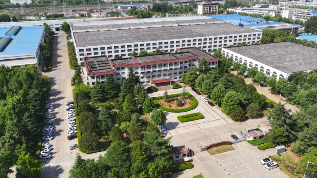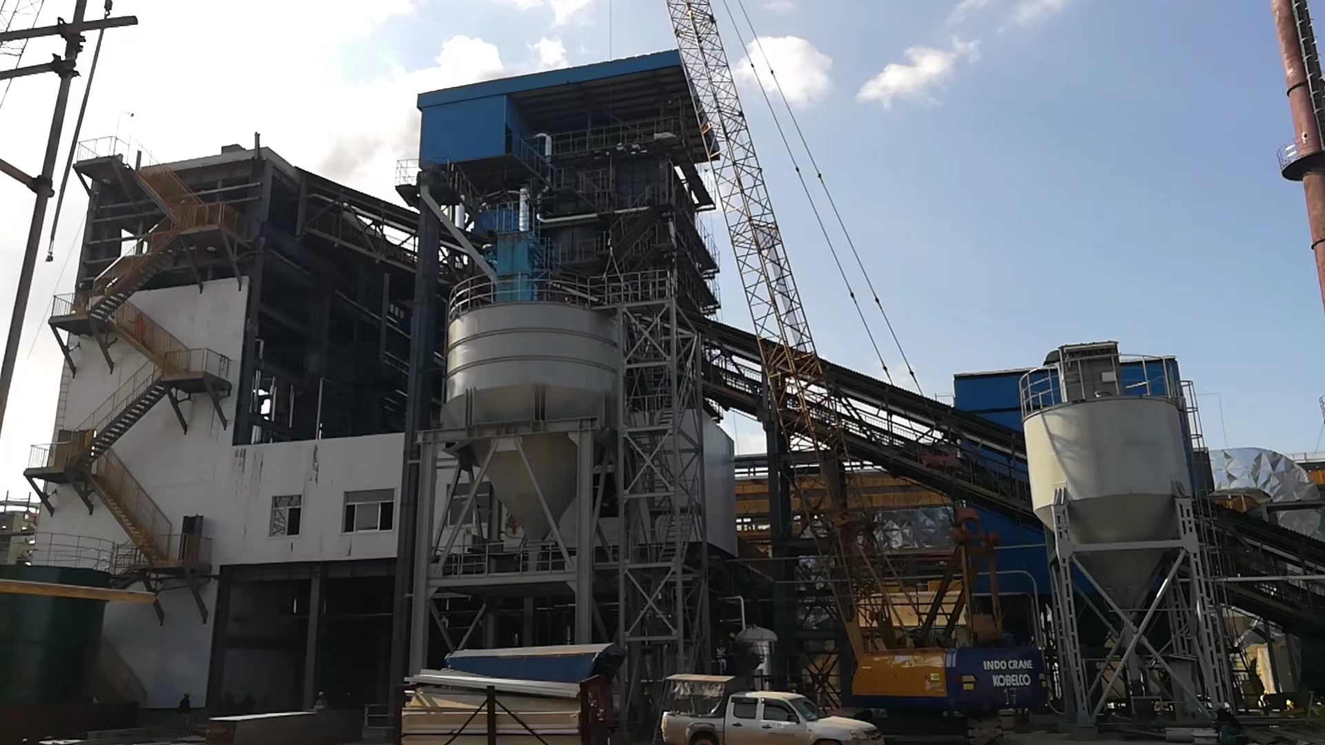
Commissioning a circulating fluidized bed boiler is where most of the serious incidents happen — not during steady-state operation, but in those first hours and days when refractory is still curing, bed material hasn’t been characterized yet, and everyone on site is under pressure to hit a handover date. Skip a step, rush a dry-out ramp, or light off before the bed temperature has truly stabilized, and you’re looking at anything from a refractory spall that costs weeks of repair time to a furnace overpressure event that injures people. The financial exposure is real: unplanned downtime on a new unit before it even enters commercial operation can run into six figures in liquidated damages alone, depending on the contract.
CFB boiler commissioning safety protocols require a structured sequence covering hydrostatic pressure testing at 1.25× design working pressure, controlled refractory dry-out over 72–120 hours with temperature ramp rates not exceeding 20–30°C per hour, cold-state air distribution verification within ±5% across all wind caps, confirmed bed temperature above 550°C before any solid fuel introduction, and continuous dual-role staffing — a certified boiler operator plus a dedicated safety observer — throughout every light-off phase.
What most pre-commissioning checklists don’t capture well is the interaction between these steps — how a shortcut in the refractory cure directly raises the risk during first coal feed, or how an air distribution test that passes on paper can still mask a half-blocked wind cap cluster that won’t show up until you’re at 60% load. The protocols covered here are sequenced the way an experienced commissioning engineer would actually walk through the plant.
Pre-Commissioning Mechanical and Structural Verification: Pressure Parts, Refractory, and Bed Material Checks
Before a single burner fires, you need to be confident that the physical plant is ready to take the load — thermally, mechanically, and structurally. In practice, this phase catches more latent problems than any other. A missed weld defect or an under-cured refractory lining will not announce itself politely; it will announce itself during first heat-up, in a way that costs weeks of downtime and sometimes worse.
Hydrostatic Pressure Testing of Pressure Parts
The hydrostatic test is non-negotiable and must be completed — and fully documented — before any thermal work begins. Per ASME Section I and EN 12952-6, the test pressure is 1.25× the design working pressure, held for a minimum of 30 minutes. For a boiler rated at 9.8 MPa design pressure, that puts you at roughly 12.25 MPa during the test. Sounds obvious, but the filling sequence matters more than most commissioning teams appreciate.
Fill from the lowest point, bleed air from the highest vents — usually the superheater headers and drum vent valves — until you get a solid water column with no trapped air pockets. Trapped air will give you a false pressure reading and can mask small leaks entirely. During the hold period, walk every accessible weld seam, fitting, and flange with a dry cloth, not just eyes. Minor weeping around a stub tube shows up as dampness that you will miss if you are only looking. Any visible leak, pressure drop exceeding roughly 0.05 MPa over the 30-minute hold, or audible deformation is a rejection. Document every test gauge ID, calibration date, and the observed pressure at 10-minute intervals. The sign-off sheet goes into the permanent boiler dossier.
Refractory Inspection: More Than a Visual Pass
Refractory problems in a CFB are insidious because the furnace shell is opaque and the lining is under mechanical and thermal stress from day one of operation. Before accepting any castable or plastic refractory work, verify anchor density against the original design drawings — spacing tolerances are typically specified at ±25 mm, and short-installed anchors in high-wear zones like the lower combustion chamber walls or cyclone barrel are a common contractor shortcut. Tap the surface systematically with a light hammer; hollow returns indicate delamination or poor bonding behind the face.
Thermal expansion joints need clearance verified physically, not by assumption. Crushed joints between panels will crack the castable during heat-up. After final set, absolutely no water washing, steam cleaning, or rain exposure is acceptable. It sounds like a basic rule but on a congested plant site with multiple trades working simultaneously, refractory panels get hosed down during dust suppression routines. Put physical barriers and signage in place, not just a verbal instruction.
Refractory curing must follow a controlled temperature ramp of 20–30°C per hour up to approximately 800°C, typically requiring 72–120 hours total, before the boiler can be brought to normal operating temperature.True
Accelerated dry-out drives steam pressure behind the castable faster than it can vent through the porous matrix, causing spalling or explosive delamination. The specific duration depends on lining thickness, ambient humidity, and castable formulation — thicker sections and humid climates push toward the longer end of the range.
Wind Cap and Air Distributor Plate Checks
The air distributor plate is where fluidization quality originates. Each wind cap must be inspected individually — not sampled — for blockage, damage, and height alignment. Caps sitting more than ±2 mm out of plane relative to the plate surface will produce uneven gas distribution, creating stagnant zones where bed material settles and sinters. That is how you get agglomeration on the first light-up, sometimes within hours.
Flow resistance uniformity across the cap population should be checked using a simple differential pressure test: apply a known supply pressure and confirm that individual cap flow rates fall within ±5% of the design value. Caps that are outside this band either have partial internal blockage — often casting flash or debris — or were manufactured off-specification. Clear blockages with compressed air and a wire probe; replace caps that are dimensionally non-conforming.
Initial Bed Material: Specification and Charge Mass
Get this wrong and you will either fail to achieve stable fluidization or damage the distributor plate during first inflation. The specified particle size distribution for typical CFB bed sand is a d50 of 0.1–0.3 mm, which corresponds to a minimum fluidization velocity in the range of 0.8–1.2 m/s at ambient conditions — the actual value depends on particle density and local air temperature. Silica sand is standard; limestone is used when in-bed sulfur capture is part of the design. Either way, the material must be clean and dry, with fines content below about 10% by mass passing 63 µm, and zero contamination by organics, clay lumps, or oversized material above roughly 1 mm that could cap a wind cap.
The minimum charge mass is calculated from the furnace cross-sectional area and the target initial bed height, typically 600–900 mm at rest. An under-charged bed starves the fluidization air and causes hot spots near the distributor. An over-charged bed creates excessive differential pressure and risks distributor damage during first inflation. The target bed differential pressure during commissioning fluidization is 4–8 kPa — below 4 kPa suggests the bed is too thin or channeling; above 8 kPa points to over-charge or partial defluidization.
Drum and Header Internal Inspection
Before closing any drum manway or header handhole, a responsible engineer must physically enter the drum (where geometry permits) or use a borescope to confirm the absence of weld spatter, loose scale, construction debris, rags, and tools. This is documented with a signed exclusion checklist. It sounds procedural, but foreign objects in a drum or header will circulate through the system during first operation, damaging attemperator nozzles, control valve seats, and instrumentation tapping points. The manway closure bolting sequence should follow the manufacturer’s torque specification, not generic practice.
Expansion Indicators and Valve Position Verification
Install all thermal expansion indicators and record zero-point baselines before any heating begins. Without a cold baseline, you cannot interpret whether thermal growth during heat-up is within the predicted range or signaling a restrained expansion point. Restrained headers and risers have caused buckled tube panels in plants where this step was skipped.
Every isolation valve, control valve, and safety valve should be function-tested and returned to its correct commissioning-start position. Tag each one — physically, with a commissioning tag, not just a logbook entry — so the status is visible during light-off without requiring someone to walk back to a control panel to verify. Safety valves need to be confirmed as unseated and free to lift; if they were gagged during transport or hydrostatic testing, confirm the gags are removed and logged out.
Loop Seal and EHE Aeration Nozzle Check
Finally, aeration nozzles in the loop seal and external heat exchanger (EHE) circuits need individual blockage checks before live operation. A blocked nozzle in a loop seal aeration header means that section of the seal does not fluidize properly, causing erratic or interrupted solid circulation — which in turn destabilizes bed inventory and combustion. The manual fluidization test at ambient conditions is straightforward: supply instrument air to each aeration port at the design flow rate and confirm that the sand sample above each nozzle shows visible movement and correct differential pressure response. Any nozzle that does not respond should be cleared or replaced before first fire-up. This check takes a couple of hours and has prevented more loop seal failures at first start than any amount of post-fire troubleshooting.
Cold-State Commissioning Tests: Air Distribution, Fluidization Uniformity, and Control Loop Validation
Cold-state testing is where a significant number of CFB commissioning failures are caught — or should be. The temptation to rush through these tests and get to first fire is real, especially when an EPC schedule is running tight, but skipping or compressing the cold-state sequence consistently creates problems that surface at the worst possible moment: mid-ramp-up, with refractory already at temperature and no clean way to abort.
Primary Air Fan Performance and Wind Box Pressure Uniformity
Start with the PA fan alone, before anything else is running. Plot the actual flow-versus-head curve across the operating range and overlay it against the design curve. Discrepancies beyond roughly 5–8% at design duty point usually point to impeller clearance issues, ductwork resistance errors in the original calculation, or a damper that was installed backwards — all of these are straightforward to fix cold and painful to diagnose hot.
Wind box pressure uniformity is the test most sites underestimate. Measure static pressure at every instrument tap across the wind box grid and verify readings fall within ±5% of the design value across all measurement points. A single dead zone here means a cold spot in the bed during operation: unburned carbon accumulates, local agglomeration follows, and you are looking at an unplanned outage within the first few hundred hours. Document the blower surge margin explicitly — CFB primary air fans operate closer to the surge line than most centrifugal fans in comparable service, and the commissioning record should confirm you have adequate margin at minimum load conditions.
Secondary and Tertiary Air Port Verification
SA and tertiary ports get less attention than they deserve. Use pitot tube traverses at each port, not just a single-point reading. Jet penetration depth — how far the secondary air stream actually reaches into the furnace cross-section — needs to match the combustion design intent. If the penetration is short, you get a reducing zone along the wall and accelerated waterwall corrosion once you are burning fuel. Check this cold, correct register angles or port geometries if needed, and re-verify before moving on.
Cold Fluidization Test Procedure
This is the most operationally revealing test in the entire cold sequence. Incrementally increase PA flow from zero upward, typically in steps of roughly 10–15% of design minimum fluidization velocity. Watch bed expansion both visually through inspection ports and through differential pressure transmitters across the bed. A healthy, uniformly fluidized bed of 0.1–0.3 mm silica sand will show a differential pressure in the 4–8 kPa range at design fluidization conditions — numbers outside that range indicate either the wrong bed depth, channeling, or wind cap blockages that were missed during the mechanical check.
If you see localized bubbling on one side while the other side stays flat, stop and investigate before proceeding. Channeling in cold state becomes dead-zone agglomeration in hot state.
Minimum fluidization velocity for standard CFB bed material (0.1–0.3 mm silica sand) is 0.8–1.2 m/s at ambient conditionsTrue
This range is consistent with published correlations for Geldart Group B particles and is routinely confirmed during cold commissioning tests on industrial CFB units; actual value depends on particle density, size distribution, and local air temperature.
ID Fan, FGR Fan, and Furnace Draft Control
Run the ID fan and FGR fan interlock tests before any fuel is anywhere near the system. The furnace draft control loop should hold target negative pressure — typically -50 to -100 Pa at the furnace top — across the full PA/SA flow range you will encounter during light-off. If the draft control hunts or saturates at low loads, tune the PID parameters now. A furnace going positive during early start-up pushes hot gas and fine particulate out of every inspection port and instrument connection in the top section. It is a real hazard and a common one.
Instrument Calibration and DCS/PLC Logic Simulation
Every pressure transmitter, thermocouple, differential pressure cell, and flow element must be calibrated against traceable standards before cold tests begin — not during, not after. Pull the calibration certificates and check the dates. Instruments sitting in a warehouse for 18 months on a delayed project have frequently drifted.
With calibration confirmed, run the DCS/PLC logic simulation by injecting artificial signals: simulate high bed temperature, low drum level, and loss-of-fluidization conditions one at a time. Verify each trip activates the correct ESD response. Emergency shutdown valves should reach full closure in ≤2 seconds from trip signal — if yours are slower, find out why before the first fire-up.
Setpoint Review Meeting and Cold-State Documentation
Before hot commissioning is authorized, hold a formal setpoint review meeting with the owner’s representative, EPC contractor, and local authority inspector all in the room. Review the alarm and trip setpoint register line by line, get sign-off, and make sure the approved version is what is actually loaded in the DCS — not a draft from three revisions ago.
The cold-state documentation package should record every test result with instrument tag, actual reading, acceptance criterion, pass/fail status, and an authorized signature. This package is not administrative paperwork. It is the only evidence you have, if something goes wrong six months later, that the unit was properly validated before fuel was introduced.
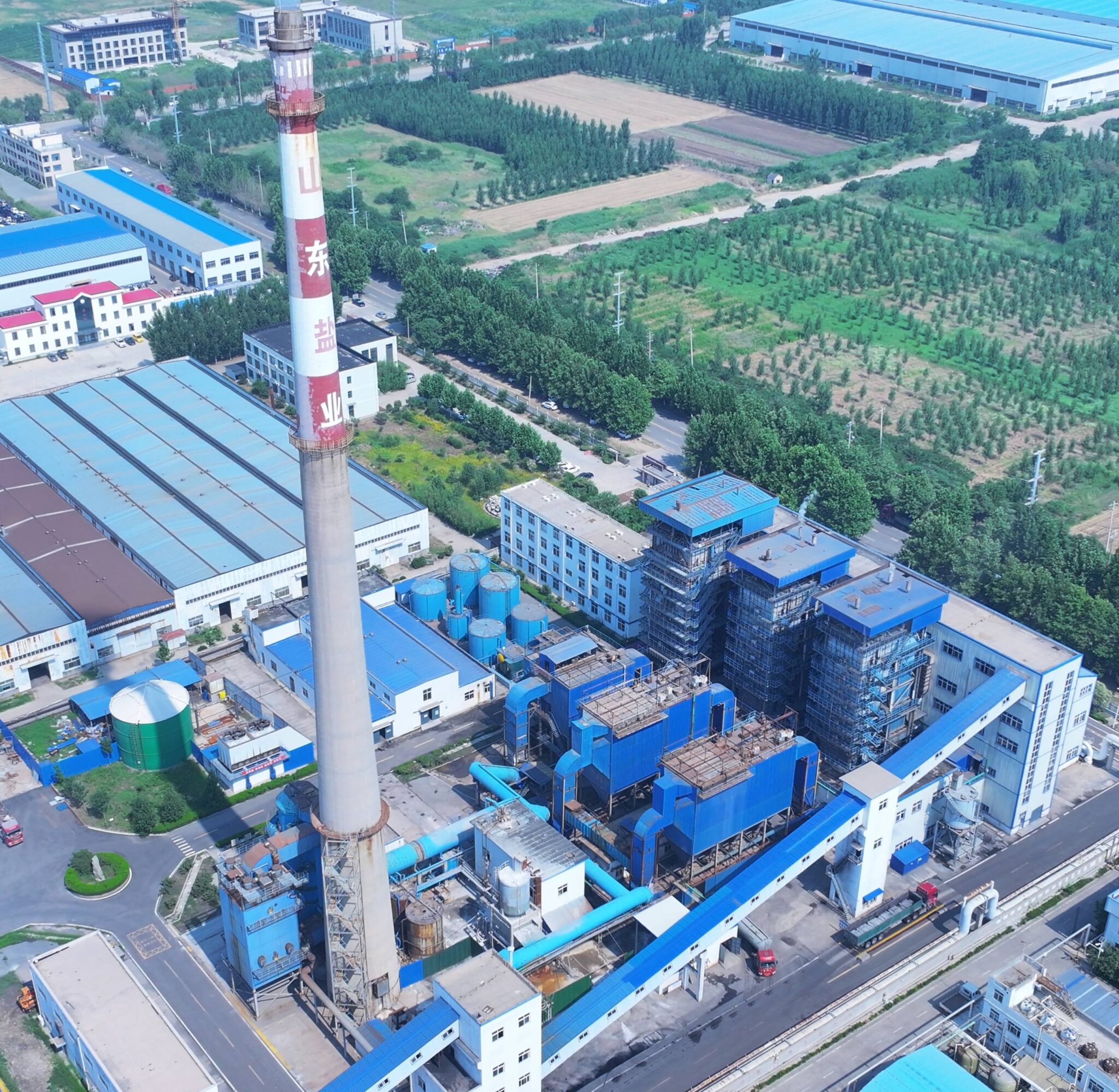
Refractory Dry-Out and First Heating Protocol: Temperature Ramp Control and Personnel Safety Zones
Refractory dry-out is the phase where most commissioning teams feel tempted to rush. The pressure to hit first-steam milestones is real, especially on EPC contracts with liquidated damages ticking. Resist it. Uncured refractory subjected to a fast heat-up will crack, spall, and in the worst case collapse into the bed — and a refractory failure inside a live CFB furnace is not a maintenance event, it’s a potential personnel casualty event.
Designing the Dry-Out Temperature Curve
The curve is non-negotiable and must be written into the commissioning procedure document before ignition day, not sketched on a whiteboard during the morning shift.
Start with a 24-hour hold at 105–120°C. This plateau does one thing: it drives off free moisture trapped in the castable matrix. Rush past it and that moisture converts to steam inside the refractory mass faster than it can escape, building internal pressure that literally blows chunks off the lining. After the moisture soak, ramp at 20–30°C per hour — that range depends on castable type and wall thickness, so confirm with your refractory supplier’s datasheet, not a generic curve. At 500°C, hold for at least 4 hours; this allows chemically bound water to release gradually. Continue the same ramp rate to 800°C, hold again for 4 hours. Some dense castables around the cyclone throat area warrant a third hold at 600°C; check the material specification.
Total elapsed time from first ignition to 800°C typically runs 72–120 hours. Any site manager asking “can we do it in 48?” needs to be shown the castable supplier’s warranty clause, which almost certainly voids coverage for accelerated cure.
Fuel Selection During Dry-Out
Use light diesel or natural gas burners exclusively. Coal is prohibited during refractory curing — full stop. Sulfur compounds from even low-sulfur coal interact aggressively with high-alumina castables before the ceramic bond has fully formed, causing surface degradation that shows up six months later as premature erosion near the burner ports and lower furnace wall. High-sulfur heavy fuel oil carries the same risk. Auxiliary oil guns at 15–30% of boiler thermal rating give you enough heat input for controlled ramp without the combustion instability that comes with trying to hold a very small coal feed rate.
Thermal Monitoring Requirements
Place at minimum one thermocouple per 10 m² of refractory surface, distributed across the lower furnace, splash zone, upper furnace walls, and cyclone barrel. Log continuously — not spot-check manually every few hours. Set a hard alarm at ±50°C deviation from the target curve at any single point. If one zone runs hot because a burner flame is impinging on the wall, you want to catch that in minutes, not at the next walkaround.
A minimum thermocouple density of one per 10 m² refractory surface is sufficient for dry-out thermal monitoring when data is continuously logged with deviation alarms.True
This density, combined with continuous logging and 50°C deviation alarms, provides adequate spatial resolution to detect localized overheating or cold spots that could indicate uneven moisture release or burner maldistribution during CFB refractory curing.
Steam, Condensate, and Drum Vent Management
Keep the drum vent wide open from ignition until drum pressure reaches 0.3 MPa. This is non-optional. Moisture driven out of the refractory, combined with the initial evaporation from water-side surfaces, needs a free escape path. A closed vent during early heating has caused drum pressure spikes on more than a few commissioning jobs — the resulting emergency blowdown wastes hours and stresses the pressure parts unnecessarily. Maintain a continuous slow drain flow from the bottom headers through this entire phase.
Personnel Exclusion Zones and PPE
Establish a hot-work perimeter of at least 10 m radius around all ignition points before lighting the first burner. Within the boiler house during firing, require fire-retardant coveralls, heat-resistant gloves rated for radiant work, and full face shields — not safety glasses. Burner peephole doors have a habit of releasing a puff of hot gas when cracked open for observation; a face shield stops that from becoming a burn injury. Assign a dedicated safety observer whose sole job during dry-out shifts is watching for abnormal sounds, visible steam release from unexpected locations, and anyone entering the exclusion zone without full PPE.
Inspection Schedule and What to Look For
Walk the furnace every 2 hours during dry-out. Listen for cracking sounds — a single sharp crack is usually the castable shrinking normally, but a series of rapid pops warrants an immediate hold on the heat-up and an inspection through all available access ports. Flag any surface crack wider than roughly 3 mm for evaluation; hairline craze cracking in dense castables is often normal, but through-cracks near expansion joints or anchor zones are not.
The Emergency Cooling Prohibition
Post physical warning signs at every water supply connection near the furnace — hose stations, service water valves, anywhere a panicked operator might reach for water if they see hot refractory. Water quenching of hot refractory causes thermal shock fracture that is orders of magnitude more destructive than the original concern. This rule must appear explicitly in the operating procedure, not just in a safety briefing that half the crew will forget by day three.
Completion Gate Before Coal Introduction
Before advancing to solid fuel commissioning, a formal refractory dry-out completion certificate must be signed by the EPC commissioning engineer and the owner’s representative. That document should confirm: the full temperature curve was followed and logged without unacceptable deviations, no structural cracking beyond acceptable limits was found, and the boiler has been allowed to cool naturally to below 100°C for a final visual inspection. Skipping this gate to save a day is how plants end up with refractory patch repairs three months into commercial operation.
First Fuel Ignition and Bed Temperature Stabilization: Step-by-Step Safe Light-Off Sequence
Light-off is where most CFB commissioning incidents actually happen. The refractory is cured, cold tests are signed off, and there’s a natural tendency for teams to relax — don’t. This phase demands more discipline than any previous step because you now have fuel, heat, and high-velocity solids circulation entering the picture simultaneously.
Pre-Ignition Checklist: Get This Right Before Striking a Flame
Before the first ignition attempt, the primary air (PA) and secondary air (SA) fans must be running at their minimum stable operating load — not just “on.” Confirm stable fan current draw and verify furnace draft is holding at the target negative pressure, typically around −50 to −100 Pa at the upper furnace, depending on your specific design. Check that all safety valves have been manually tested for free movement and reseat correctly. Drum water level should sit at normal commissioning water level (NWL); do not start a light-off with a borderline low reading because thermal expansion during warm-up will throw your level control into a transient immediately.
Critically, confirm at least two independent bed thermocouple measurement points are live, calibrated, and displaying on the DCS. One probe is not acceptable — if it fails mid-sequence, you’re flying blind. Some plants I’ve seen try to proceed with a single functional thermocouple because the spare was damaged during refractory work. That’s an abort condition.
Oil or Gas Burner Ignition Sequence
Establish the pilot flame first, confirm it visually if the observation port allows, then bring in the main start-up burner. UV or IR flame detectors must confirm main flame within the configured proving time — typically 10 to 15 seconds — before the burner control system proceeds. If flame is not confirmed, the fuel valve must shut automatically and a purge cycle must complete before any retry. This is not a step to override manually under pressure from a commissioning schedule.
Hold at minimum burner load for a full five minutes after main flame confirmation. The start-up burner capacity should be in the range of 15–30% of total boiler thermal rating; going in harder than that early in the sequence risks localized overheating of bed material before circulation is properly established.
Bed Temperature Monitoring During Initial Heating
Log all bed thermocouple readings manually every five minutes regardless of what the DCS trend historian is doing — the paper record matters for incident investigation if something goes wrong. Watch the spread between individual probe readings. If any single point runs more than 100°C above the bed average, that’s a local hot spot: reduce burner load, increase PA flow slightly to improve fluidization, and investigate before continuing the ramp. Hot spots at this stage usually indicate a dead zone in fluidization, possibly a partially blocked wind cap that passed the cold-state test at tolerance but is marginal under warm conditions.
The 550°C Threshold: Why It Is Non-Negotiable
Introducing solid coal fuel before the bed reaches 550°C stable temperature risks accumulation of unburned fuel in the bed, which can ignite explosively as temperature rises.True
Below approximately 550°C, coal volatile matter and fines do not ignite reliably or consistently. Unburned fuel accumulates in the bed and cyclone return. When bed temperature eventually rises past the ignition threshold, the accumulated fuel can release energy rapidly, causing a pressure excursion or deflagration event inside the furnace.
This is the single most important temperature checkpoint in the entire commissioning sequence. Do not let schedule pressure move it.
Coal Feed Initiation and Load Stepping
Once bed temperature has stabilized above 550°C — stabilized meaning holding for at least ten minutes without a declining trend — start the coal feeder at 10–15% of maximum continuous rating (MCR) feed rate. Watch the downstream bed thermocouple response. You should see a gradual temperature rise within two to three minutes; if you see nothing, something is wrong with fuel delivery or combustion, and you stop increasing feed.
Step the feed rate up in 5% increments of MCR rate, with a minimum ten-minute stabilization hold at each step. Rushing this is how you get a bed temperature runaway or a combustion imbalance between the primary and secondary combustion zones.
Stack Emissions Monitoring During Coal Introduction
If your CEMS isn’t calibrated yet — which is common at this stage — run portable SO₂, CO, and O₂ analyzers at the stack. Record baseline readings at each feed rate step. CO concentration is your early warning of incomplete combustion; a rising CO trend while O₂ is still adequate usually points to poor fuel distribution or insufficient bed turbulence. These baseline readings also serve as your compliance reference during performance testing later.
Abort Criteria: Know These Before You Start
Any of the following conditions requires immediate safe shutdown: bed temperature deviation greater than 150°C between any two measurement points; furnace pressure excursion beyond ±500 Pa of setpoint for more than 30 seconds; bed differential pressure dropping below 3 kPa indicating fluidization loss; or any safety valve lifting. A single safety valve lift tells you the system has reached set pressure unexpectedly — find out why before resuming.
Post-Ignition Stabilization Hold
Once you reach roughly 60% MCR, hold there for a minimum of four hours. Don’t attempt a full load ramp until this observation period is complete. Pressure parts are still thermalizing, refractory is seeing its first real operating temperatures, and expansion joints are moving for the first time under live conditions. Four hours gives the team time to walk down every accessible joint, penetration, and expansion seal visually — issues that don’t show up on instrumentation often show up as a wisp of steam or a hot patch on the casing.
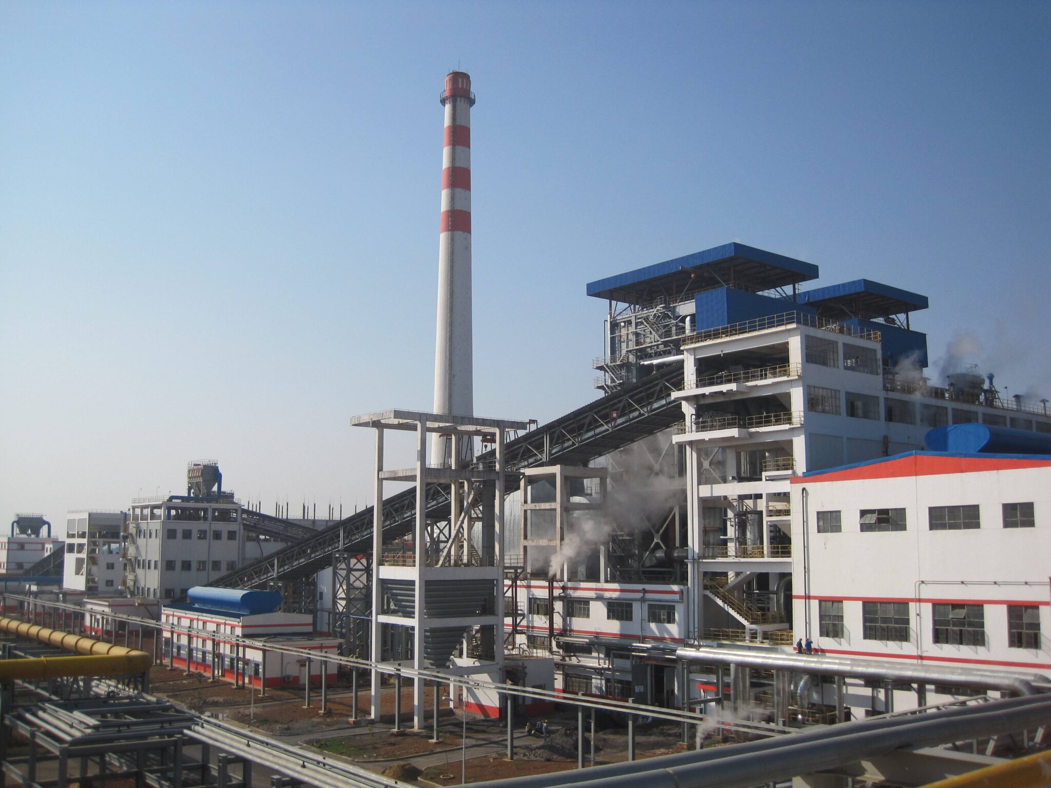
Critical Interlock and Trip System Validation During Live Commissioning
Live commissioning is where shortcuts kill people. Every interlock that wasn’t proven cold will eventually be tested by the plant itself — usually at the worst possible moment. Systematic validation of each safety interlock and emergency shutdown function, while the unit is live and under controlled conditions, is non-negotiable. It is also legally required under most jurisdictions before a boiler can be handed over for commercial operation.
Interlock Defeat Permit System
Before any interlock is bypassed for testing purposes, a formal written defeat permit must be issued, reviewed, and signed off — typically by the commissioning engineer, the plant safety officer, and the owner’s representative. Four hours is the practical ceiling for any single bypass period; if the test cannot be completed within that window, the interlock is restored, a new permit is raised, and the reason for overrun is documented. No exceptions.
During any active bypass, a dedicated operator — not someone who also has other tasks at that moment — must maintain manual monitoring of the protected variable. If you bypass the low drum level trip to test feedwater valve response, someone is physically watching that drum level gauge and level transmitter readout the entire time. This sounds obvious. In practice, it gets skipped when the commissioning schedule is running behind.
Master Fuel Trip Functional Testing
Each MFT condition must be induced individually and sequentially. You do not test all triggers simultaneously. The standard set covers low drum level, high furnace pressure, loss of fluidization signal (bed differential pressure dropping below roughly 3 kPa), and induced draft fan trip. For each condition, the acceptance criterion is full closure or shutdown of all fuel feeds, the start-up burner, and the primary air fan within ≤2 seconds from trip signal. Response time is measured from the DCS event log, not estimated visually.
If any fuel feed feeder takes 3.5 seconds to respond because the actuator is undersized or the control signal cable has a loose termination, that gets fixed before the test is signed off. A two-second benchmark sounds tight until you realize a runaway bed temperature event can move 50°C in under a minute at full fluidization velocity.
Drum Level and Bed Temperature Protection
Three-element drum level control validation requires demonstrating that the high-high level setpoint trips the feedwater pump correctly, and that the low-low level setpoint triggers the fuel trip. Both must actuate with documented timestamps. In my experience, the LLL fuel trip is the one most likely to have wiring errors discovered at this stage — worth a careful check of the loop drawing before the test.
Bed temperature high-high protection is tested by simulating a runaway temperature signal at the DCS. The expected response is coal feeder shutdown, start-up burner trip, and opening of the emergency bed drain valve in sequence. The sequence matters; if the bed drain opens before the fuel supply is cut, you introduce a combustion air short-circuit that can make the situation worse.
Emergency shutdown valve response time should be ≤2 seconds from trip signal to full closure per ASME and EN 12952 commissioning standards.True
Both ASME and EN 12952 frameworks specify rapid ESD valve actuation requirements to prevent pressure excursions and fuel accumulation events during emergency shutdowns. The 2-second benchmark is widely cited in burner management system standards including NFPA 85.
Flue Gas O₂ Trim and Relief Valve Verification
Oxygen trim control is commissioned across the 40–100% load range. The acceptance criterion is ±0.5% O₂ deviation from setpoint after load stabilization — tighter than that is usually unrealistic with the lag inherent in a CFB furnace; looser than that means your combustion efficiency and CO emissions will drift. The PA/SA ratio control loop should be exercised through at least three load steps before the result is accepted.
Safety relief valves are verified as set and sealed at the lift pressures specified on the boiler design certificate. Do not re-set, re-spring, or tamper with factory-sealed valves on site. If a valve lifts prematurely during commissioning, that is a signal the system pressure transient exceeded expectations — investigate the cause rather than adjusting the valve.
DCS Historian Integrity and Final Acceptance Report
Every trip actuation, interlock response, and alarm acknowledgment must appear in the DCS historian with accurate, synchronized timestamps. A commissioning team that cannot reconstruct the sequence of events from the data record after an incident is exposed to serious liability. Run a deliberate test: induce a non-critical alarm, acknowledge it, then pull the historian record and verify the timestamp matches the control room clock within two seconds.
The final interlock validation report documents every individual test result, the measured response times, any deficiencies found and corrective actions taken, and witness signatures from the owner’s representative and — where specified in the contract — a third-party inspection body. That report is the gate. Performance guarantee tests do not begin until it is formally accepted and filed. Plants that skip this step to recover schedule usually end up losing far more time when an unvalidated interlock fails during the guarantee run itself.
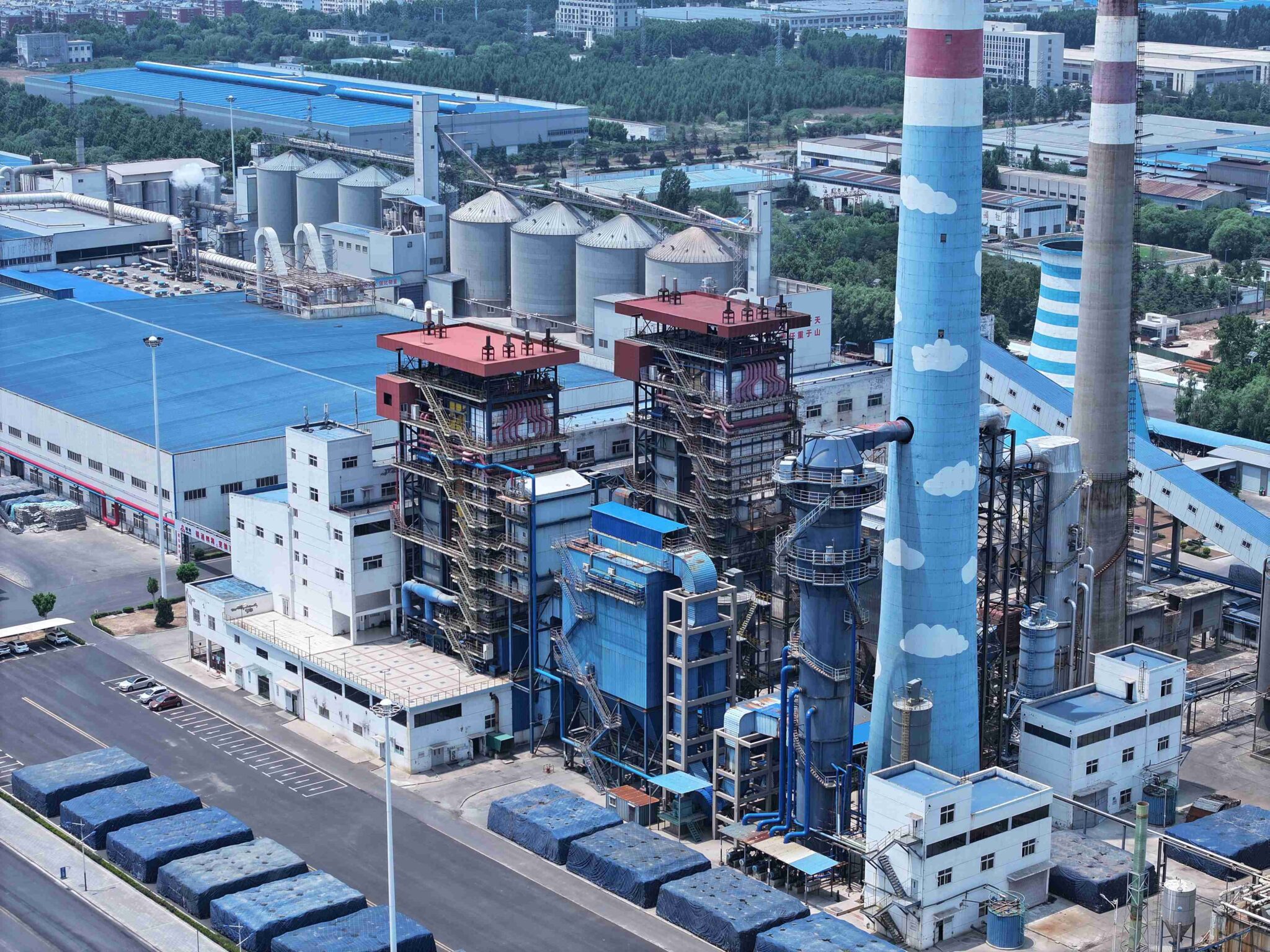
Hazard Control for Ash Handling, Flue Gas, and High-Temperature Surface Exposure During Commissioning
CFB commissioning teams spend most of their pre-fire energy on pressure parts and refractory. Understandable — but the injury incidents I’ve seen documented most often during first firing aren’t pressure failures. They’re burns from hot ash drain lines, CO exposure at leaking expansion joints, and contact burns from unlagged ductwork that nobody thought to fence off. These hazards are predictable and largely preventable, but only if you treat them as engineered control problems rather than common-sense reminders.
Bottom Ash Drain and First Bed Drain Hazard
The first intentional bed drain during commissioning will produce ash in the 600–800°C range, depending on how long the bed has been at operating temperature and what bed material is loaded. That is not a number to hedge — it’s roughly the temperature of dull-red to bright-orange metal. Gravity will move that material fast, and standard work gloves are irrelevant at that temperature.
Require the water-cooled ash cooler to be fully commissioned, operationally proven, and flow-tested before any intentional drain is opened. This means cooling water supply and return isolated, flow confirmed, outlet temperature monitored. Manual handling of hot bed ash without full PPE — at minimum leather spats, aluminized apron, face shield, and insulated gloves rated to 1000°C — is prohibited. In practice, the smarter control is procedural: nobody handles drain product during commissioning; it goes into a lined collection vessel and is left to cool. Simple, but it needs to be written into the commissioning operating procedure, not just assumed.
Fly Ash Collection System Sequence and Blowback Risk
Bag filters and ESPs both need cold functional verification before flue gas is routed through them. Check hopper level indicators, rotary valves or chain conveyors, and screw discharge systems under air-flow conditions before live gas. A plugged hopper on day one of combustion doesn’t announce itself politely — it backs up, the hopper pressurizes, and the next time a cleaning cycle fires or an access hatch is cracked, you get a hot ash blowback event. Confirm every level switch is calibrated and alarmed. Bag filter inlet temperature protection interlocks should also be proven during this phase; routing 900°C+ flue gas into a fabric filter that hasn’t reached design operating temperature will destroy the bags in minutes.
Flue Gas Leakage Monitoring During First Firing
CFB casings operate under slight negative pressure in balanced-draft designs, but expansion joints, access doors, and duct flanges can leak in both directions depending on load transients. Deploy portable CO and O₂ monitors at all these points during first firing. The area alarm threshold for personnel exposure is 25 ppm CO — that’s the OSHA ceiling for an 8-hour TWA, and in confined or semi-enclosed areas around ductwork, concentrations can spike well above that if there’s a seal failure.
Don’t rely on smell or visible haze. CO is odorless, and flue gas leakage at low concentrations is invisible.
Cyclone Separator Access Prohibition
Cyclone separator body temperatures during operation run well above 200°C on external surfaces if insulation is incomplete or missing. Hard LOTO procedures apply to all manholes and inspection ports: locked shut, tagged, and surface temperature placards posted. The argument that “we just need a quick visual” is exactly how contact burns happen. No access during live commissioning, period.
All high-temperature surfaces within 2 m of walkways must be insulated before personnel access during live commissioningTrue
This aligns with standard industrial thermal insulation and personnel protection requirements under IEC, OSHA 29 CFR 1910, and EN ISO 13732-1, which define 60°C as the threshold for contact burn risk on reachable surfaces.
Hot Surface Insulation Completion Before Zone Access
Any surface above 60°C within 2 m of a walkway, platform, or working area must be fully insulated and clad before personnel are permitted in that zone during live operation. This isn’t aesthetic — EN ISO 13732-1 defines 60°C as the contact burn threshold for metal surfaces. During commissioning, it’s common for insulation to lag behind installation progress. The control here is a formal zone-access checklist: a supervisor signs off that insulation is complete and surface temperatures have been spot-checked with an IR thermometer before the zone opens to commissioning staff.
Pressure Part Hot-Work Exclusion
No welding, grinding, or cutting within 3 m of any pressurized component while the system is live without a signed hot-work permit and a dedicated fire watch. This sounds obvious. It gets violated during commissioning when a small punch-list item — a bracket weld, a cable tray grind — gets handed off to a subcontractor who wasn’t in the commissioning safety briefing. A permit system with a physical standby observer stops that.
Loop Seal Aeration Monitoring and Surge Protection
Loop seal aeration flow must be monitored continuously once solid circulation is established. If aeration supply pressure drops below the design minimum — typically caused by a control valve fault or supply header pressure drop — the loop seal can lose its seal function, and you get an uncontrolled return of hot solids into the lower furnace. This creates both a thermal surge and a potential bed-temperature spike that can accelerate agglomeration. Set a low-aeration alarm with an automatic load-reduction response; don’t wait for the operator to notice manually.
First Ash Sample Collection
After roughly 8 hours of stable coal combustion — not 8 hours from first coal feed, but 8 hours of genuine stable load — collect bed ash and fly ash samples. Particle size distribution and unburned carbon content (UBC) in fly ash will tell you whether excess air is calibrated correctly and whether combustion efficiency is in the expected range before you run formal performance tests. High UBC in early samples usually points to either insufficient excess air or bed temperature running low; either way, you want to know before the performance acceptance test, not during it.
Load Ramp-Up Safety Protocol: From Minimum Stable Load to Maximum Continuous Rating
Getting to first ignition is the milestone everyone photographs. The load ramp that follows is where CFB boilers actually punish you for cutting corners.
Thermal mass in a large CFB unit — all that refractory, the thick drum shell, the pendant superheater headers — does not respond forgivingly to aggressive load swings, especially during a first cold start when everything is still equilibrating. The structured ramp procedure below is not formality. It’s what separates a clean commissioning from a drum ligament crack or a superheater tube failure you don’t discover until the guarantee test.
Load Ramp Rate Limits and Bed Temperature Surveillance
The working ceiling during a cold-start ramp is 3–5% MCR per 15-minute step, and the specific rate within that range depends on refractory age (freshly cured brick is more sensitive), ambient temperature, and how uniform the bed temperature profile looked during light-off. If any single bed thermocouple deviates more than 80°C from the average of its zone during a ramp step, hold the load and do not advance until the deviation closes. That 80°C threshold is not arbitrary — it signals either a local defluidization pocket or a partially blocked wind cap that wasn’t caught during cold-state testing. Advancing through it risks bed agglomeration, and recovery from an agglomerated bed mid-commissioning costs days, not hours.
Drop the ramp rate to 2% per 15 minutes the moment you see that deviation. If it persists across two consecutive hold periods, initiate a controlled load reduction and investigate.
Steam Pressure Rise and Drum Stress Management
Below 3 MPa, limit steam pressure rise to roughly 0.1 MPa per minute. Above 3 MPa, cut that to 0.05 MPa per minute. Drum stress calculations for most industrial CFB designs assume this kind of controlled pressurization; exceeding it doesn’t necessarily cause immediate visible damage, which is exactly why it’s dangerous — fatigue accumulates silently across multiple commissioning cycles and surfaces as a crack during normal operation six months later.
Log superheater outlet header metal temperatures every 10 minutes throughout the ramp. If any point approaches the design limit minus a 20°C margin, hold. Do not interpret “design limit” loosely here — use the value from the boiler manufacturer’s thermal design document, not a general materials reference. On high-alloy headers (T91, TP347H), the consequence of exceeding that margin even briefly is creep damage that voids the tube warranty and isn’t visible externally.
Feedwater System Changeover at 40% MCR
The BFP changeover from the start-up pump to the main boiler feed pump should happen at roughly 40% MCR. In practice, some teams delay this because the changeover feels like a disruption mid-ramp. Don’t. Running the start-up pump past its designed operating range causes cavitation and puts unnecessary stress on the de-aerator level control. Confirm de-aerator temperature and pressure are on-spec before the changeover — a de-aerator running cold at this point means dissolved oxygen carryover into the boiler, which starts pitting the economizer surfaces from day one.
Sootblowing Prohibition in the First 24 Hours
No sootblowing during the first 24 hours at load. Ash deposit layers on tube banks are unstable and poorly bonded early in commissioning. Premature sootblowing sheds large clumps rather than fine particles, and those clumps can physically impact and dent economizer tubes or jam convective pass gaps. The thermal shock from steam jets on tubes that haven’t yet stabilized to steady-state temperature gradients creates additional risk. Mark this as a formal prohibition in the operating procedure, not a recommendation.
Steam Consumer Synchronization for EPC Projects
On EPC projects feeding a downstream process plant, coordinate the steam supply ramp directly with the process plant’s startup lead engineer. Steam header pressure must stay within ±0.2 MPa during load transfer events — wider swings will trip process control valves and potentially force a rapid load rejection back onto the boiler, which is exactly the kind of uncontrolled transient the ramp procedure is designed to avoid. Hold a joint coordination call before the 75% MCR hold point so both teams understand the handoff sequence.
Mandatory Hold Points and Owner Sign-Off
Define formal 30-minute observation holds at 50%, 75%, and 100% MCR. The owner’s engineer signs the commissioning log at each hold before the team advances. These aren’t bureaucratic checkboxes — they’re the moments when an experienced outside observer looks at vibration, flue gas color, bearing temperatures, and ash discharge behavior with fresh eyes. Skipping sign-off to save a few hours has a documented history of leading to disputes about whether performance deficiencies were pre-existing or operational damage.
Baseline Performance Recording at 100% MCR
At 100% MCR hold, record everything: steam output (t/h), steam temperature and pressure at the main stop valve, feedwater temperature, excess air (from flue gas O₂ analyzer), stack temperature, and calculated boiler efficiency. This dataset is the baseline against which the formal performance guarantee test will be judged. If you don’t capture it under controlled steady-state conditions right now, you will spend weeks arguing about operating conditions during the guarantee test.
CFB boilers require a more rigorous load ramp protocol than equivalent-capacity pulverized coal boilers due to the thermal mass of the refractory-lined combustion chamber and the sensitivity of the fluidized bed to combustion instability during transients.True
CFB combustion chambers are heavily refractory-lined and operate with a dense bed of hot circulating solids, both of which create larger thermal gradients during ramp transients compared to the comparatively thin-walled furnace walls and suspension-fired combustion of a PC boiler at equivalent capacity.
Commissioning Team Roles, Emergency Response Plan, and Site Safety Management
The most technically rigorous commissioning procedure in the world fails if the wrong people are in the room — or if nobody is clearly in charge when something goes wrong at 2 a.m. on day three of first fire. Human-system interface is where CFB commissioning safety either holds together or unravels.
Minimum Team Composition and Who Must Actually Be Present
Six roles are non-negotiable during any live-fire activity. The lead commissioning engineer — a boiler specialist with direct CFB experience, not just water-tube boiler background — carries overall technical authority. A DCS/instrumentation engineer must be stationed at the control room, not on-call from a hotel. A mechanical inspector covers rotating equipment, expansion joints, and refractory visual monitoring. The certified boiler operator handles direct firing controls and is the only person authorized to execute light-off steps. A safety officer enforces the exclusion zones, PTW system, and access control — this role cannot be doubled up with any operational function. The owner’s representative witness provides contractual sign-off at each commissioning milestone and, frankly, keeps the EPC team honest.
All six must be physically present during ignition, load changes, and any trip event. Not reachable by phone. Present.
Competency Verification Before the Start
Every boiler operator on the team must hold a valid national or internationally recognized certificate — GB/T or equivalent for most markets, ASME S-stamp jurisdictions where applicable. The EPC contractor is responsible for providing credential documentation to the owner before mechanical completion sign-off. In practice, this gets skipped or deferred constantly, and then becomes a serious liability issue if an incident occurs. A simple credential register — operator name, certificate number, issuing authority, expiry date — should be submitted and accepted at least two weeks before commissioning start.
CFB boiler operators require specific certification before legally operating the boiler during commissioning.True
Most national boiler safety regulations (including Chinese TSG G6001, EU Pressure Equipment Directive frameworks, and various national equivalents) require operators of pressure vessels and boilers above defined thresholds to hold valid, current operation certificates. Operating without these during commissioning creates legal and insurance liability.
Emergency Response Plan: Written for CFB-Specific Scenarios
A generic plant ERP is not sufficient. The CFB-specific ERP must define response procedures — with named role assignments, not job titles — for at least six scenarios: pressure-part tube rupture, furnace explosion (defluidization-induced or fuel accumulation), refractory collapse, ash system fire (particularly in the external heat exchanger or loop seal region), toxic flue gas release at the baghouse or stack, and total utility power failure. Each scenario gets its own one-page response card posted in the control room and at the local instrument panel. Response roles must be assigned to actual people on the shift roster, updated every shift.
Before the first fuel ignition, the team conducts a full tabletop drill covering all six scenarios — attendance documented, gaps recorded, corrective actions assigned with deadlines. Then a partial live drill: a simulated tube leak response, including simulated ESD activation and team evacuation from the furnace bay. Lessons learned from both drills feed directly back into the ERP before it’s finalized. Teams that skip the live drill almost always discover communication gaps or physical access problems — locked gates, missing PPE at muster points — that would have cost them badly in a real event.
Communication and Shift Handover
Radio channel discipline matters more than people expect in a CFB plant during commissioning. Assign dedicated channels: one for operations, one for maintenance/mechanical, one for safety officer direct. Verbal handover is not sufficient — every shift ends with a written log transfer covering current boiler state, any active PTWs, outstanding alarms, and pending hold points. The escalation chain goes: site operator → shift lead engineer → plant manager → EPC project director, with maximum two-hour response time at each level for anything above routine status.
Permit-to-Work From Day One
The PTW system activates at mechanical completion, not at first fire. Any activity involving energy isolation (LOTO on ID fan drives, for example), confined space entry into the loop seal or ash hopper, hot work near insulation or refractory, or work above 2 m requires a valid PTW signed by the responsible engineer. The safety officer maintains the PTW register and physically posts the active permits at the job location. In my experience, the highest-risk window for PTW violations is actually the cold commissioning phase — the plant feels less dangerous, supervision is lighter, and people take shortcuts they wouldn’t take with flame on.
Near-Miss Culture and Incident Reporting
Zero-barrier near-miss reporting means anyone on site can log a near-miss without fear of blame, using a simple paper or tablet-based form at the site entrance. All near-misses get reviewed at the daily commissioning meeting — takes maybe ten minutes, and it’s worth every one of them. Critical near-misses — anything involving pressure boundary, energy release, or personnel exposure — get escalated to the EPC safety director within two hours, full stop.
Fatigue Management During Intensive Phases
First-fire sequences push teams hard, and fatigue is a genuine risk factor that commissioning schedules routinely underestimate. Maximum shift length during intensive commissioning is 12 hours. Mandatory 8-hour rest between shifts. No single engineer should serve as sole responsible person for more than two consecutive days during first-fire and initial load ramp sequences. On a tight schedule this requires overlapping staffing — budget for it. A tired lead engineer making a fuel feed decision at hour eleven of a twelve-hour shift is a risk that no interlock system fully compensates for.
Frequently Asked Questions About CFB Boiler Commissioning Safety
These questions come up repeatedly — from procurement managers finalizing contracts, from plant engineers preparing for first fire, and from EPC site supervisors who discover gaps in their commissioning plans about three weeks too late. Answers here are based on what actually happens on site, not what the ideal schedule says.
What is the minimum bed temperature before you can introduce coal?
550°C is the standard threshold, and it’s not arbitrary. Below that temperature, the bed cannot reliably ignite coal volatiles as they evolve during devolatilization. What happens instead is gradual accumulation of unburned combustibles in the furnace — and when ignition eventually does occur, you get a pressure spike that can damage the refractory crown, blow seals, or worse. The 550°C figure also depends on stabilization: the bed needs to hold that temperature for several minutes across multiple thermocouple readings, not just touch it momentarily on one probe. In practice, operators watching a single point thermometer have been caught out by this. Use at least four distributed bed temperature readings and confirm they’re all above threshold before opening the coal feed gate.
How long does full commissioning take for a 75 t/h CFB boiler?
Plan for 45–75 days from mechanical completion to performance guarantee test acceptance. The wide range is real — it depends heavily on fuel moisture and sizing consistency, site utility readiness (compressed air, instrument air, cooling water), how far behind the ash handling and auxiliary systems are relative to the main boiler, and local regulatory inspection scheduling, which in some jurisdictions can add 10–15 days of waiting time that nobody budgets for. A well-prepared site with experienced local operators, pre-staged bed material, and no punch-list carryover from civil works can hit the lower end. A site where the ID fan VFD commissioning gets delayed, or where the bag filter inlet temperature protection wasn’t calibrated, will slide toward 75 days or beyond.
Can refractory dry-out and hydrostatic pressure testing run at the same time to save time?
No. Full stop. The pressure test must be completed, accepted, and — critically — all water drained and the system confirmed dry before any heating begins. Residual water trapped behind refractory lining or in backing insulation converts to steam during curing and has nowhere to go. The result is spalling, cracking, or in severe cases explosive delamination of the lining. Sequence discipline here is non-negotiable.
Hydrostatic pressure testing at 1.25× design working pressure per ASME/EN 12952, held for a minimum of 30 minutes, must be completed and the boiler fully drained before refractory dry-out heating commences.True
Running these two phases concurrently risks steam entrapment in refractory backing material, which causes cracking or explosive spalling during the thermal curing ramp — a well-documented failure mode in CFB and other refractory-lined boilers.
What causes most CFB commissioning delays?
Four things dominate, in rough order of frequency: substandard initial bed material (wrong particle size distribution or moisture content requiring a full dump and recharge), refractory curing shortcuts taken under schedule pressure that result in cracking discovered at first load, instrumentation calibration backlogs where thermocouples, pressure transmitters, and flow meters haven’t been loop-checked before light-off, and auxiliary systems — particularly ash conveyors, bottom ash coolers, and bag filters — that simply aren’t ready when the main boiler is. The auxiliary systems issue is underestimated. You cannot commission a CFB meaningfully if you have nowhere to put the ash.
Is third-party inspection mandatory?
Requirements vary by country. As a practical benchmark, any project above roughly 10 MW thermal or operating pressure above 1.6 MPa warrants engaging an accredited inspection body to witness the hydrostatic pressure test, verify safety valve set points and discharge, and sign off on interlock test records. Beyond regulatory compliance, the documentation generated — stamped test certificates — becomes the paper trail that protects both the EPC contractor and the plant owner if a warranty dispute arises later.
What fuel flexibility is permissible during commissioning?
During initial commissioning through performance guarantee testing, use only the primary design fuel. This is not about being overly conservative — it’s about establishing a clean, interpretable baseline. If you introduce a blend or alternative fuel before baseline performance is confirmed, you lose the ability to separate fuel-related issues from equipment issues when something doesn’t meet specification. Alternative fuels, biomass co-firing ratios, or blended coal grades should come after the performance guarantee test is signed off, with both the plant owner and EPC engineer in agreement.
What documentation should the plant owner receive at commissioning completion?
The minimum handover package: as-built drawings for all pressure parts and piping, the hydrostatic test certificate, safety valve test certificates (set pressure, lift, reseating), the full interlock and trip test report with response time data, the refractory dry-out temperature log (hour-by-hour), the performance test report with guaranteed versus achieved values, O&M manuals in the agreed operating language, and complete DCS logic documentation including I/O list and alarm setpoint register. Missing items in this package are not minor administrative oversights — they create real operational risk when shift operators need to diagnose a trip event six months after the commissioning team has left.
How does Taishan Group support overseas customers through this process?
Taishan assigns on-site commissioning engineers who remain through performance guarantee testing, not just light-off. Local operator training starts before the engineers depart the factory — typically a structured session covering DCS operation, routine startup/shutdown, and trip response. DCS remote diagnostic access allows Taishan’s engineering team to review live operating data and trend logs without requiring an emergency site visit for every early-life issue. Spare parts for high-wear items — wind caps, seal pot refractory, bed drain valves — are staged at site before commissioning begins rather than ordered reactively. At completion, a commissioning certificate with actual performance data is issued, providing the plant owner with a documented baseline for future reference.
References
BPVC Section VII — Recommended Guidelines for the Care of Power Boilers — ASME
Annual Reminder for Restart of Boilers — Startup Checks and Safe Starting Sequence — National Board of Boiler and Pressure Vessel Inspectors
Recommendations for a Safe Boiler Room — National Board of Boiler and Pressure Vessel Inspectors
Circulating Fluidized Bed Boilers — CFB Boiler Technology — GE Vernova
Circulating Fluidized Bed Boilers — Valmet
Circulating Fluidized Bed Boiler Technology — Mitsubishi Power
Circulating Fluidized Bed Boilers — ANDRITZ
Water for the Boiler — Boiler Water Treatment and Safety — Spirax Sarco
Basic Steam Boiler Operator Training — Startup, Shutdown, Controls and Safety — Spirax Sarco
Boiler Owner and Operator’s Guide — Safe Steam Boiler Operation — National Board of Boiler and Pressure Vessel Inspectors