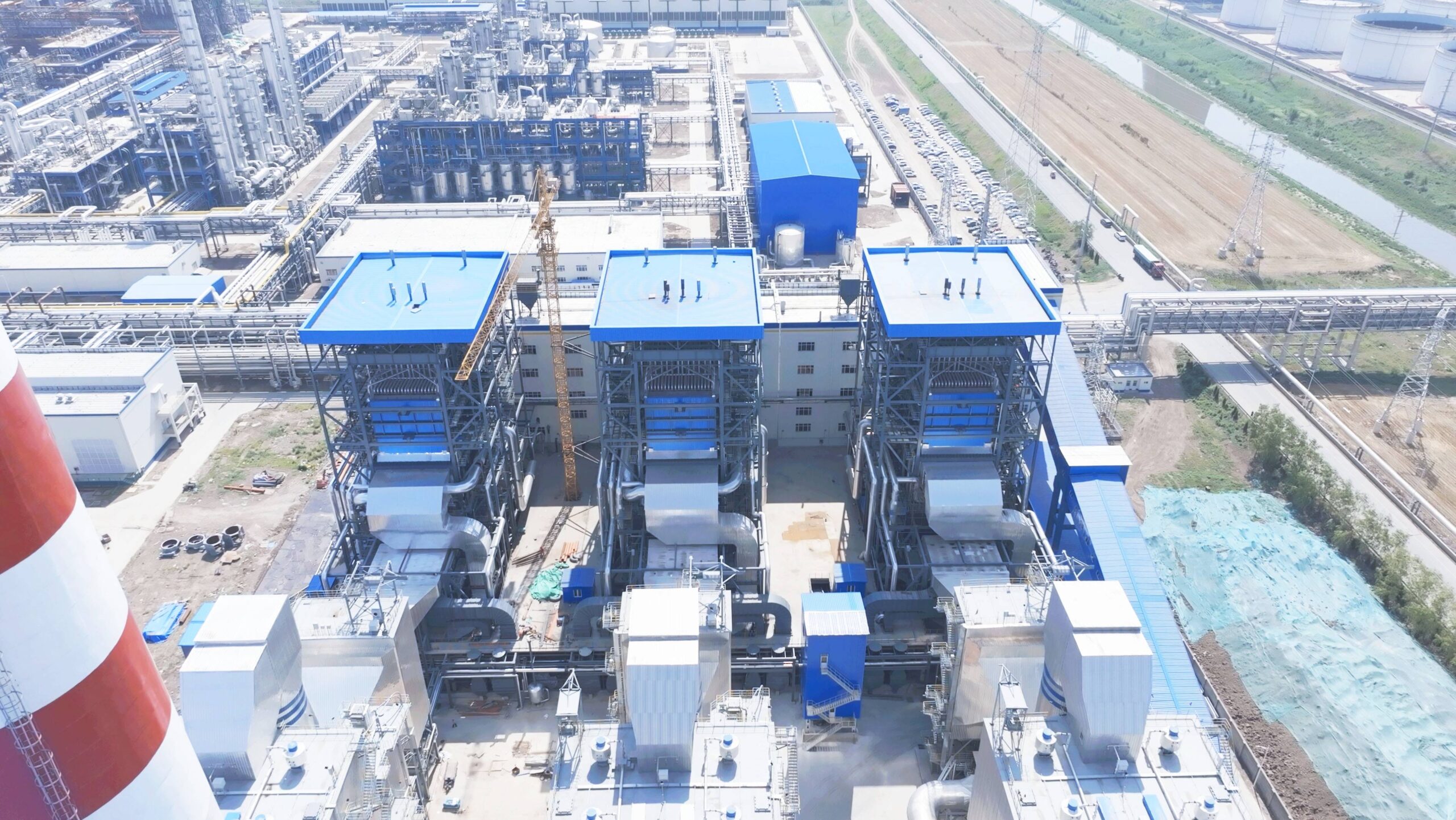
Skipping proper startup and shutdown sequences on a CFB boiler is one of the most reliable ways to shorten refractory life by years, not months. A single uncontrolled heat-up — bed temperature climbing too fast before the castable has stabilized, or a cold-start rushed past the 550–650°C auxiliary fuel threshold because someone wanted steam on the header by a certain shift — can crack furnace wall refractory panels that cost tens of thousands of dollars to patch and take a week of outage to fix properly. That’s before you count the scrap generation from unstable combustion during an improper coal feed initiation, or the emissions exceedances that come back as regulatory exposure.
A CFB boiler cold startup typically requires 4–8 hours from ambient to full load, governed by a drum pressure ramp rate of roughly 0.05–0.1 MPa/min and strict bed temperature milestones: auxiliary ignition fuel cuts in at 550–650°C, coal feed begins at 650–750°C, and full coal load is only permitted above 850°C. Shutdown cooling must stay within 50–80°C/hour for the first four hours to protect refractory integrity.
What makes CFB procedure discipline genuinely different from other boiler types — and harder to enforce — is the interaction between the bed material, the refractory mass, and the combustion chemistry happening simultaneously. Get any one of those three out of sync with the others, and the consequences aren’t always immediate. Sometimes you don’t see the damage until the next scheduled inspection, by which point the root cause is two startups ago and nobody’s written it down.
Pre-Startup Inspection Checklist: Mechanical, Instrumentation, and Refractory Readiness
A forced outage on hour two of a cold startup — because someone skipped the drum level gauge calibration or left a cyclone inspection port unsealed — is exactly the kind of event that turns a planned 6-hour light-off into a 2-day nightmare. The checklist below isn’t a bureaucratic formality. Every item maps to a real failure mode.
Pressure Parts and Water Side
Start with hydrostatic test documentation if any pressure-part maintenance occurred since the last shutdown. No test record, no startup — full stop. Confirm drum water level gauges read consistently across both the local gauge glass and the remote transmitter; a discrepancy of more than ±25 mm between them typically means a root valve is partially blocked or the transmitter zero has drifted. Both conditions will give you a false low-water trip within the first hour of firing.
Boiler feedwater pump interlock function needs a live test, not just a visual check. Cycle the duty pump off and confirm the standby cuts in within the response window specified by your controls vendor — usually 3–5 seconds. Deaerator dissolved oxygen should be at or below 7 ppb before feedwater enters the drum; anything higher accelerates pitting corrosion on waterwall tubes, which you won’t see until you have a tube failure during operation.
Air and Flue Gas Path
FD and ID fan blade pitch or damper position needs to be verified at the mechanical zero point, not just confirmed on the DCS screen. In practice, linkage wear and seasonal temperature swings shift the actual blade angle away from what the position sensor reports. A windbox pressure transmitter loop check — signal injection from the field instrument back through to the DCS display — should be standard before every cold start.
Cyclone separator inspection ports must be physically confirmed sealed and bolted. It sounds trivial until you find that a maintenance crew left one cracked open, and you’re chasing a furnace pressure oscillation for an hour trying to find the leak. If the plant uses a fabric filter, confirm all compartments are energized and that the compressed-air pulse cleaning system has dry instrument air — moisture in the pulse headers causes bag failures within weeks. ESP energization should be verified against the high-voltage transformer interlock before flue gas flow begins.
Bed Material and Fuel System
Static bed height should fall in the 300–500 mm range; the right value for your unit depends on furnace cross-section and design fluidization velocity, so check the OEM documentation rather than guessing. Bed material particle size distribution matters more than most operators realize — particles outside the 0.1–0.3 mm range for a typical coal-fired CFB either elutriat too fast or defluidize and cause hotspots. If the unit has been sitting idle and the bed was exposed to moisture, sample the material and check for agglomeration before you try to fluidize.
Coal feeder calibration — gravimetric or volumetric — should be confirmed against a weigh-test run at minimum and maximum feed rates. Limestone injection system valve sequencing needs a dry-run stroke test; a stuck isolation valve during SO₂ exceedance is an emissions compliance event, not just an operational nuisance.
Bed material particle size outside the 0.1–0.3 mm specification range will not significantly affect CFB combustion stability.False
Oversized particles resist fluidization and create defluidized zones that concentrate heat at the bed surface, risking refractory damage and combustion instability. Undersized particles elutriat rapidly, reducing bed inventory and combustion efficiency. Particle size distribution is a primary design parameter for CFB fluidization quality.
Refractory Status Verification
This is the item most often shortcut under schedule pressure, and it causes the most expensive damage. New or repaired refractory requires a dry-out curve — typically 72–120 hours with staged temperature holds, depending on refractory type, thickness, and the manufacturer’s specification. Skipping or compressing this curve drives steam pressure buildup within the castable matrix, which spalls the lining from the inside out.
Document the last inspection date and any crack findings from the previous shutdown. Hairline cracks under roughly 1 mm width in non-critical areas are usually acceptable between major inspection intervals, but anything wider, or any cracking near expansion joints or cyclone entry ducts, warrants repair before the next fire.
Safety Interlock and Trip System Functional Test
Every trip function must be proven with a live signal, not assumed from last month’s test. That means the master fuel trip relay, high drum pressure trip, low water level trip (both first-stage alarm and trip setpoint), loss-of-fluidization trip based on windbox differential pressure, and furnace pressure excursion trip. Walk each one through from the field sensor to the final trip actuator. A trip system that hasn’t been tested is not a trip system — it’s a label on a panel.
Startup authorization should require a signed checklist, not just a verbal confirmation from the shift supervisor.
Utility Systems
Instrument air pressure should be stable and within the range your control valves require — typically 0.5–0.7 MPa — and dryness matters; a pressure dew point above -20°C in humid climates causes valve positioner failures at the worst moments. Cooling water flow to all fan bearing housings needs to be confirmed flowing, not just the header pressure. Seal air fan operation on the coal feeders and classifier seals should be verified running at correct differential pressure before any coal enters the system.
Sootblower steam supply isolation should be positively confirmed closed until the unit reaches stable operating pressure — premature sootblowing on a cold furnace erodes refractory and does nothing useful. Ash removal system — whether pneumatic, mechanical drag chain, or clinker grinder — should be jogged through a test cycle to confirm no blockages or seized components before bed ash starts accumulating.
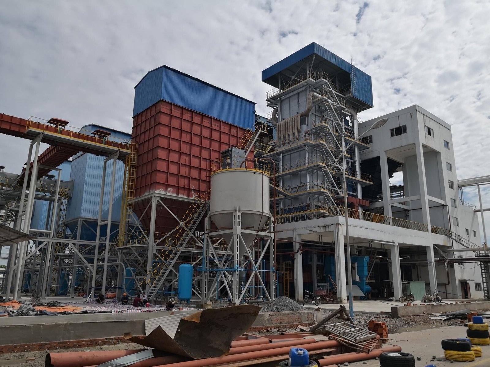
Cold Startup Procedure: Refractory Warm-Up, Bed Ignition, and Load Ramp to Full Capacity
A cold start on a CFB boiler — meaning the unit has been at ambient temperature for more than 72 hours, or has had any refractory repair since the last shutdown — is where procedural discipline pays off most directly. Rush it, and you’re looking at refractory spalling, thermal shock to drum internals, or a bed slump that takes hours to recover. Each stage below feeds directly into the next; skipping or compressing any of them is how plants end up with forced outages on day two.
Stage 1: Establish Fluidization Air Before Any Heat Source Goes Live
Start the FD fan and set the windbox airflow to roughly 1.2–1.5 times the minimum fluidization velocity — in practice, this works out to a superficial velocity somewhere between 1.0 and 1.5 m/s depending on your bed material particle size and bulk density. Don’t guess this from memory; read the windbox-to-furnace differential pressure across each nozzle zone. You’re looking for a uniform distribution across the full grate. A spread greater than about 20% between zones usually means a partially blocked nozzle or uneven bed inventory — both of which need to be corrected before ignition. Trying to warm up an unevenly fluidized bed just bakes a problem in deeper.
Stage 2: Light the Auxiliary Ignition Burners and Respect the Moisture Zone
Once fluidization is confirmed uniform, bring the oil or gas ignition lances online. Ramp furnace temperature at no more than 80–100°C per hour through the 100–300°C range. This is the moisture evolution zone — both free and chemically bound water in the refractory brickwork and castable needs to exit gradually. Push too fast here and the steam pressure build-up inside the refractory matrix causes micro-cracking you won’t see until six months later when a section spalls into the bed.
If any refractory was patched or replaced during the outage, hold at 300°C for a minimum of 60 minutes. Some OEM cure schedules call for 90 minutes or longer for dense castable sections. Check your refractory manufacturer’s data sheet — not just the boiler OEM manual — because the two sometimes disagree, and the castable specification governs.
Stage 3: Bring Bed Temperature Up to the Coal Ignition Window
Continue the temperature ramp toward 550–600°C. As you climb through this range, start introducing secondary air gradually — typically beginning at 20–30% of design secondary airflow — to begin shaping the furnace combustion profile before any solid fuel is present. Watch all bed thermocouples simultaneously. A spread of more than ±50°C between measurement points at this stage suggests channeling or a dead zone. Investigate before proceeding.
Stage 4: First Coal Introduction — the Critical Confirmation Step
Once bed temperature reaches 650°C uniformly across the grate zone, initiate the coal feeder at minimum rate: roughly 10–15% of design coal flow. Do not start at a higher rate hoping to accelerate the startup — this is the single most common mistake on plants that have been running long enough to get complacent.
Coal ignition in a CFB bed can be confirmed by monitoring CO2 concentration in flue gas rather than relying solely on bed temperature rise.True
Rising CO2 in flue gas, combined with a sustained or increasing bed temperature trend, gives dual confirmation that combustion has actually initiated. Bed temperature alone can be misleading during early coal feed because the ignition burners are still contributing heat.
As combustion stabilizes — usually within 10–20 minutes of first coal introduction — begin stepping down auxiliary fuel in proportion to the coal heat input, keeping total heat release roughly constant. Resist the urge to kill the burners completely until coal feed is above roughly 25–30% of design rate and bed temperature is holding steady above 750°C on its own.
Stage 5: Drum Pressure Ramp and Steam System Preparation
During the early heating stages, drum vents and superheater drain valves should be open. Keep them open until you have a measurable steam flow establishing through the system. Ramp drum pressure at 0.05–0.1 MPa per minute — the lower end of that range applies to older drums or units that haven’t been hydrostatically tested recently; the upper end is typical for well-maintained units in regular service. Before superheater outlet temperature approaches design value, confirm that attemperator spray water supply is available and that the control valve responds correctly. A stuck spray valve discovered at full pressure is a bad moment.
Stage 6: Load Ramp to Full Capacity
Increase coal feed in increments of roughly 10% of design load, with a stabilization hold of at least 15 minutes at each step. Watch the cyclone return leg temperature and the loop seal differential pressure — these are your indicators that solids circulation has properly established. A loop seal that isn’t pressurized correctly will allow furnace gas to bypass the cyclone return, and you’ll see erratic bed inventory behavior that looks like a feed problem but isn’t.
Before declaring full load, verify that stack emissions — SO2, NOx, and CO — are within permit limits at the actual operating load. Limestone injection rate may need to be trimmed during the ramp-up phase since desulfurization efficiency changes with bed temperature and Ca/S ratio. Reaching full megawatt output while running a stack violation isn’t a successful startup.
Warm and Hot Restart Procedures: Managing Residual Bed Heat and Pressure Vessel Stress
The distinction between a warm restart and a hot restart is not semantic — it determines whether you can skip refractory warm-up holds, how aggressively you can ramp air flow, and what your primary combustion risk actually is. Get the classification wrong and you are either wasting 2–3 hours on unnecessary holds, or you are introducing fuel into a furnace that is already above coal ignition temperature without a proper purge. Neither outcome is acceptable.
Classifying the Restart: Warm vs. Hot
The threshold that matters is bed thermocouple temperature, not time offline alone. If your bed thermocouples read 300–550°C and the unit has been offline for roughly 4–24 hours, that is a warm restart. If bed temperature is still above 550°C and offline time is under 4 hours, you are in hot restart territory. Drum metal temperature is a cross-check, not the primary criterion — but it matters for stress calculations later. A boiler that sat for 6 hours after a grid trip on a cold winter night could have a bed that cooled faster than expected; always read the thermocouples before you assume anything about thermal state.
Bed thermocouple readings, not elapsed time alone, should determine restart classification in CFB boilers.True
Cooling rate varies with ambient temperature, ash bed depth, and whether fluidization air was left on at idle. A boiler offline for 5 hours in a cold climate may have a bed temperature well below 400°C, while the same unit in a tropical plant could still read above 500°C. Time is a rough proxy; actual temperature measurement is the only reliable classifier.
Skipping refractory warm-up holds is permissible only when documented temperature logs — continuous thermocouple recording, not operator memory — confirm the refractory has not dropped into the range where free moisture could be present. In practice, that means confirmed readings above roughly 200°C throughout the hold period since last operation. If logging has a gap, treat it as a cold start.
Warm Restart Sequence
Restore fluidization air before anything else. Residual hot spots in the bed can cause local agglomeration if particles sit stagnant; even a few minutes at minimum fluidization velocity will re-homogenize temperature distribution and confirm the bed is still fluid. Watch differential pressure across the bed — a sluggish or flat response suggests settling or partial defluidization, and you need to resolve that before introducing fuel.
Once bed fluidity is confirmed, fuel introduction can proceed more aggressively than a cold start, but the 50°C/hour limit through any temperature band where refractory moisture risk exists still applies. That ceiling is not arbitrary; refractory cracking from steam pressure buildup inside the lining is a slow failure mode that shows up as spalling weeks later, not immediately.
Hot Restart Sequence
The primary hazard here is uncontrolled combustion. If bed temperature is above 550°C and there is residual fuel — unburned coal or char from the trip — reintroducing combustion air without a proper purge can cause a rapid, uncontrolled heat release. The purge procedure must confirm stable oxygen concentration in the furnace exit gas before fuel feed resumes. Oxygen should be steady, not climbing, which tells you active combustion of residuals has concluded.
Drum pressurization during a hot restart requires careful management. If the unit tripped under load, drum pressure may have partially decayed but the drum metal is still hot. The pressure-to-temperature relationship must stay within the OEM-specified stress window — typically expressed as a P/T curve in the design documentation. If grid synchronization is not yet available, use the high-pressure bypass or dump station to control steam pressure rise rate rather than letting pressure build unchecked against a closed main stop valve.
Solids Inventory and Loop Seal Checks
During any offline period, solids settle. In a warm or hot restart, the loop seal and return leg may have an uneven solids distribution — denser packing at the bottom of the return leg is common after an unplanned trip where circulation stopped abruptly. Re-establish circulation gradually; a sudden surge of solids back into the furnace can cause a pressure excursion in the cyclone and distort bed temperature readings temporarily. In my experience, this is one of the more commonly overlooked steps in abbreviated restart procedures, and it shows up as erratic bed pressure differential in the first 15–20 minutes after coal feed starts.
Documentation and Restart Permits
Many jurisdictions — and most insurance policies on larger utility-scale units — require a signed restart permit from a qualified engineer after any unplanned shutdown exceeding a defined duration, often 4 or 8 hours depending on local regulation. Typical checklist items: confirmation of cause-of-trip investigation and clearance, instrumentation loop checks (especially bed thermocouples and drum level transmitters, which are the instruments most likely to have been disturbed by a trip event), refractory inspection log, and fuel feed system readiness. A restart permit is not bureaucratic overhead — it is the one forcing function that makes sure someone with actual authority has reviewed the thermal state before the unit comes back online.
Normal Controlled Shutdown Procedure: Load Reduction, Bed Cooldown, and System Isolation
Planned shutdowns are where most refractory damage actually happens — not during operation, but during the cool-down that follows. A rushed or poorly sequenced shutdown can crack furnace walls that survived years of cycling, contaminate the bed with unburned carbon, or leave the pressure vessel in a state that adds two hours to the next startup. The sequence below reflects what a controlled, deliberate shutdown looks like in practice.
Load Reduction Phase
Start backing off coal feed in roughly 10% decrements of rated throughput, with stabilization holds of at least 10–15 minutes between steps. Don’t rush this. At each step, watch bed temperature distribution across all thermocouple zones — uneven cooling at part load is one of the earliest signs that a section of the bed is starting to defluidize locally, usually because air distribution is no longer uniform at the reduced fluidization velocity. If you see one zone dropping 30–40°C faster than adjacent zones, bump the FD fan speed slightly before continuing the ramp-down.
Limestone feed is easy to forget during shutdown sequencing. As coal rate drops, sulfur capture efficiency tends to fall because bed temperature is declining and residence time distribution shifts. If your plant has SO₂ compliance obligations during the entire shutdown window — which many do under continuous emissions monitoring — increase the limestone-to-coal ratio by 15–25% during the lower load steps. The exact ratio depends on coal sulfur content and your current Ca/S design basis, but erring toward more limestone here costs almost nothing compared to an emissions exceedance.
Auxiliary Fuel Re-Introduction
Once coal feed drops below roughly 25–35% of full load (the exact threshold depends on your fuel’s heating value and bed inventory), bed temperature will start drifting below the stable combustion range faster than most operators expect. Reintroduce the ignition burners — typically light fuel oil or natural gas — before bed temperature falls below 650°C. Don’t wait until it’s already dropped to 580°C and you’re chasing it back up. The goal is a smooth handoff from coal combustion to auxiliary fuel, maintaining bed temperature in the 650–700°C band until coal feed stops entirely.
Coal Feed Cutoff and Bed Burnout
After coal feed stops completely, keep fluidization air running and maintain auxiliary fuel for 20–30 minutes. This burns out residual carbon trapped in the bed material. Skipping this step leaves unburned carbon that can smolder, produce CO surges when air flow is eventually reduced, and create localized hot spots during the next startup. Confirm CO concentration below 200 ppm at the stack — or at the furnace outlet if you have in-situ measurement — before you begin reducing air flow. In my experience, plants that skip the burnout phase often find elevated CO readings puzzling on the next cold start. It’s the same carbon that never left.
Maintaining fluidization air and auxiliary fuel for 20–30 minutes after coal feed cutoff is sufficient to reduce residual bed carbon and prevent post-shutdown CO accumulation.True
Sustained fluidization at temperatures above 650°C with supplemental fuel support provides adequate oxygen contact time to oxidize residual bed carbon to acceptable levels before air flow reduction, consistent with standard CFB post-combustion burnout protocols.
Controlled Bed Cooldown
Reduce FD fan speed in gradual steps, staying above minimum fluidization velocity for as long as the bed temperature profile allows — typically until bed temperature falls below 400°C, after which the fluidization benefit diminishes. Below that point, the bed won’t re-ignite spontaneously, and you have a choice to make: hot standby or cold preservation.
Hot standby means keeping a low air flow through the bed to prevent settling and maintain some thermal uniformity. It’s gentler on refractory and shortens the next startup considerably, but it consumes auxiliary power and requires someone monitoring the system. Cold preservation — draining bed material to the ash hopper — is cleaner for extended outages but subjects the refractory to a full thermal cycle every time. Plants that cycle weekly tend to accept the parasitic load of hot standby; plants doing planned maintenance shutdowns lasting several days usually drain. Neither is universally right.
Cooling rate is the non-negotiable constraint throughout. Refractory thermal stress scales with gradient, not absolute temperature, and the first four hours post-trip are when the risk is highest. Log every thermocouple zone every 30 minutes. If any zone drops faster than 80°C per hour — some conservative OEM specs put the limit at 50°C per hour for castable refractory sections — you need to slow it down. Options include partially opening an access door in a controlled, symmetrical way, or in cold weather, keeping the ID fan at a very low speed to prevent excessive natural draft pull through the furnace. Applying ceramic fiber blanket over inspection ports sounds low-tech, but it works.
Steam System Isolation
Close the main steam stop valve only after pressure has stabilized at or below your target isolation pressure. Open drains and vents in the correct sequence per your P&ID — superheater drains first, then drum vents. Allow drum pressure to decay naturally. Forced rapid blowdown to speed up the cooldown is tempting but genuinely risky: flash evaporation in the drum creates mechanical stress that accumulates invisibly over years and tends to show up as hairline cracking around nozzle welds during the inspection you weren’t planning for.
| Shutdown Phase | Key Parameter to Monitor | Risk If Ignored |
|---|---|---|
| Load reduction (>30% load) | Bed temperature uniformity across zones | Localized defluidization, uneven wear |
| Part load (<30%) | Bed temp vs. 650°C threshold | Bed quench, difficult restart |
| Coal cutoff + burnout | CO concentration at outlet | Post-shutdown CO surge, carbon carryover |
| Bed cooldown | °C/hour by zone, first 4 hours | Refractory cracking |
| Steam isolation | Drum pressure decay rate | Flash stress at drum nozzles |
The whole sequence from first load reduction to confirmed safe isolation typically runs 3–6 hours for a well-executed planned shutdown, depending on unit size and initial load. Trying to compress it below 2.5 hours on a large unit usually means something got skipped.
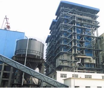
Emergency Shutdown Response: Trip Scenarios, Immediate Actions, and Safe State Verification
A controlled shutdown gives you time. An emergency shutdown does not. The difference matters enormously in a CFB boiler, because the combination of hot bed inventory, pressurized steam circuits, and refractory mass means a poorly managed trip can turn a recoverable event into a multi-day outage — or worse.
Master Fuel Trip: What Fires Automatically and Why You Don’t Override It
The Master Fuel Trip (MFT) is the boiler’s last line of defense before a dangerous condition becomes a catastrophic one. Typical automatic MFT initiation conditions include high drum pressure (usually set at 105–110% of design operating pressure), low drum level below the second low setpoint, loss of any forced draft (FD) fan, high furnace pressure beyond roughly +2 to +3 kPa above setpoint, and flame failure confirmed across all burner scanners.
When MFT fires, it acts simultaneously: all coal feeders and auxiliary fuel valves close, FD and ID fans shift to purge mode, and emergency feedwater injection initiates to protect drum level. This happens in seconds. The operator’s role right after MFT is not to reset it — it is to confirm execution. Walk the fuel valve panel and verify position feedback against physical indicators. On older DCS installations I’ve seen in plants running early 2000s-era Siemens or ABB systems, valve position feedback can lag or occasionally misread, so a visual check of the valve actuator itself matters more than the screen says.
Do not attempt MFT reset until the root cause is positively identified and documented. That sounds obvious; in practice, production pressure makes it less obvious at two in the morning.
Loss of Fluidization: The Clock Starts Immediately
Bed defluidization is one of the more insidious CFB failure modes because it can develop quietly — a partially blocked windbox nozzle, an FD fan that trips on thermal overload, or a duct damper that drifts shut. Without adequate fluidizing air, bed material compacts, temperature gradients develop rapidly, and clinker can form within minutes at operating temperatures.
Immediate actions: confirm FD fan status on the DCS and at the motor control center, then check windbox differential pressure — a drop below roughly 0.8–1.2 kPa (depends on bed inventory and nozzle design) is a reliable early indicator of poor distribution. If bed temperature is reading above 950°C and you cannot restore fluidizing air within approximately 5 minutes, begin emergency bed drain. Waiting longer risks ash agglomeration that will require mechanical cleaning and potential nozzle plate replacement. Refractory damage from localized hot spots at this stage is also a real possibility, particularly at the lower furnace walls.
Furnace Pressure Excursions: Positive and Negative Are Different Problems
A positive pressure trip (furnace pressure rising sharply, sometimes called a puffback) and a negative pressure trip have completely different root causes and require different immediate responses.
Positive pressure excursions usually trace to ID fan trip or damper runaway on the outlet side — suddenly, combustion gases have nowhere to go. Immediate action is to verify ID fan status and move outlet dampers toward their fail-safe open position manually if the actuator has failed. Simultaneously reduce FD fan output to cut combustion air supply.
Negative pressure excursions — furnace going strongly negative — typically indicate FD fan overspeed, a damper that has opened too far on the inlet side, or in rarer cases a duct collapse creating an unintended flow path. Strong negative pressure draws cold air in-leakage through inspection ports and expansion joints, which can thermally shock refractory and distort structural casing members. The fix is to throttle FD fan output and check inlet damper positioning. If pressure does not stabilize within 60–90 seconds, consider a manual trip to prevent structural damage.
An emergency furnace pressure trip caused by ID fan failure can cause refractory cracking from thermal shock if cold air in-leakage is sustained for more than a few minutes.True
Rapid cold air ingress into a hot furnace (900°C+) creates steep thermal gradients in refractory linings. Most CFB refractory specifications limit allowable thermal shock to temperature changes below 50–80°C per hour in the post-trip cooling phase; a sudden cold air surge far exceeds this, particularly at expansion joints and inspection port surrounds.
Post-Trip Safe State Verification
Before anyone opens an inspection port or drain valve, the furnace must be confirmed in a genuinely safe state. The sequence:
- Complete furnace purge with at least 5 full air volume changes at purge airflow — typically 25–30% of full-load FD fan capacity, run for a minimum of 5–8 minutes depending on furnace volume. This is not optional and should not be shortened under schedule pressure.
- All fuel isolation valves confirmed closed — position feedback AND visual confirmation at the valve body.
- Drum pressure below roughly 0.2 MPa before any inspection port is cracked open. Higher pressures can eject hot gas or bed material unexpectedly.
- Flue gas oxygen at the economizer outlet above 10% to confirm no combustible accumulation remains. Some plants use a portable flue gas analyzer as a secondary check if the in-situ O₂ probe has been unreliable.
Equipment Damage Assessment Before Any Restart Authorization
The trip log is your most important document at this stage. Pull the exact sequence of events — what tripped first, what followed, what the bed temperature and pressure traces looked like in the two minutes before the trip. This sequence often tells you whether the trip was a symptom or a cause.
Physically, check refractory at the lower furnace, cyclone inlet, and cyclone refractory liner through available inspection ports. Hairline cracking from thermal shock is sometimes visible; more serious spalling may have deposited material on the cyclone floor. Probe the bed drain valve to confirm free movement — if bed material has agglomerated, the drain valve will resist operation and you will know before restart that you have a clinker problem to resolve first.
Restart authorization should be a signed document, not a verbal call. In most plants I’ve worked with, the chief engineer or shift superintendent holds that authority. Under Chinese TSG regulations, EU PED requirements, and ASME jurisdictions, any emergency trip resulting in detectable pressure boundary damage, a fire, or a pressure excursion exceeding defined limits must be reported to the local boiler inspection authority before restart. The documentation package typically includes the DCS trip log, a written incident description, the damage assessment findings, and corrective action records. Skipping this step creates regulatory exposure that far outlasts whatever production schedule pressure drove the decision.
Refractory Protection Strategy Across the Full Startup-Shutdown Thermal Cycle
CFB boilers are harder on refractory than almost any other combustion equipment in industrial service. You have abrasion from circulating solids, thermal cycling that never fully stabilizes in high-utilization plants, and wildly different thermal environments within a single pressure vessel — sometimes within a few meters of each other. Getting the refractory strategy right is not a commissioning-week activity. It has to be embedded in every startup, every shutdown, and every outage plan from day one.
CFB-Specific Refractory Zones and Why They Fail Differently
The dense-phase bed zone — roughly the lower furnace from the air distributor up through the splash zone — sees moderate operating temperatures, typically 850–950°C under normal coal combustion, but the highest particle velocity and abrasion loading in the system. Failure here is usually erosion wear, not thermal spalling. High-density chrome-corundum or SiC-based castables are standard in this zone, and you should expect to inspect wear depth annually. The upper furnace is the opposite situation: temperature can spike to 950–1,050°C during load transients, but particle loading is lower, so thermal fatigue and differential expansion at anchor zones are the dominant failure modes.
The cyclone separator combines both problems simultaneously. Hot gas at 850–900°C, dense particle flux, and a geometry that creates turbulent impingement on the inlet duct and barrel wall — this is the zone that fails first in most plants that skip a controlled dry-out or push cold startups too fast. Erosion breakthrough at the cyclone inlet is not a slow failure; once the wear liner is compromised, the outer insulating layer follows within weeks. The loop seal runs cooler, typically 750–850°C, but sees continuous high-flux particle movement. The failure mode there is usually at anchor points and construction joints rather than in the body of the castable.
New Refractory Dry-Out: Why the Hold Schedule Exists
Fresh castable contains both free moisture and chemically bound water. Free moisture drives off below 120°C; the chemically bound water releases between roughly 250–450°C through dehydration reactions. If you ramp through those ranges too fast, steam pressure builds inside the castable matrix faster than it can escape, and you get internal fracturing that is invisible from the outside — until the liner spalls during the second or third operating cycle.
A properly designed dry-out curve holds at approximately 110°C for 12–24 hours (free water removal), 250°C for 8–12 hours (onset of dehydration), 450°C for 8–10 hours (complete dehydration of dense castable), and 650°C for 4–8 hours before transitioning to the normal ignition sequence. Insulating castable is more sensitive than dense castable because its lower thermal conductivity traps steam longer. Refractory brick dry-out is faster — brick is pre-fired — but the mortar joints still need the lower-temperature holds. Do not treat brick-lined zones as exempt from the curve.
Skipping or compressing the 250–450°C hold range during initial refractory dry-out is the single most common cause of premature castable spalling in CFB boilers commissioned under schedule pressure.True
Chemically bound water in calcium aluminate and high-alumina castables dehydrates in this temperature band; insufficient hold time causes internal steam pressure buildup that fractures the castable matrix before it has developed full hot-strength.
Thermal Cycling Fatigue Over the Plant Lifetime
Every cold start introduces a new thermal cycle, and monolithic castable accumulates micro-crack damage with each one. In high-cycle plants — say, daily or twice-weekly cycling, common in industrial steam supply or grid-response peaking applications — major refractory replacement in cyclone separators and the lower furnace typically becomes necessary every 3–5 years. Baseload plants running continuous campaigns of 4,000–6,000 hours between outages can push 7–10 years before major replacement, depending on fuel ash chemistry and bed material quality.
The practical implication: if your plant dispatch profile changes from baseload to cycling, your refractory maintenance budget needs to change with it. This is something procurement managers on EPC projects frequently underestimate when fuel flexibility or grid interconnection requirements shift after the original boiler specification is locked in.
Inspection Protocol Between Outages
During every planned outage, a refractory condition register should be updated with findings from at least three methods. Borescope inspection through existing access ports covers areas that are geometrically inaccessible from inside the furnace. External thermal imaging of the furnace shell — done while the unit is still warm, ideally within 8–12 hours post-shutdown — identifies hot spots where liner thinning or delamination has allowed heat to conduct outward; a reading 30–50°C above the surrounding shell temperature is worth investigating immediately. Hammer-tap survey of accessible castable surfaces helps identify delaminated sections; the hollow sound is unmistakable once you know what you’re listening for.
Repair Material Compatibility
Patching during a short outage is tempting and sometimes necessary, but mismatched repair materials cause more damage than they fix. The thermal expansion coefficient of the patch material must match the parent castable. Using a generic patching compound on a chrome-corundum lined zone because it was available in the maintenance store is a mistake that typically propagates the crack boundary out another 50–100 mm per subsequent cycle. Always verify the patch product datasheet against the original lining specification.
Engineering Support for Overseas EPC Installations
Taishan Group develops boiler-specific refractory dry-out curves as part of the commissioning documentation package for CFB boiler EPC projects. For overseas installations — where local contractors may have no prior CFB experience — the standard package includes a staged temperature hold schedule tailored to the actual castable products used in that build, a thermal cycle management guideline for the first year of operation, and remote technical support during the initial dry-out firing. In practice, this matters most at sites where the commissioning team and the refractory crew are not the same organization and neither has seen the OEM’s documentation in full.
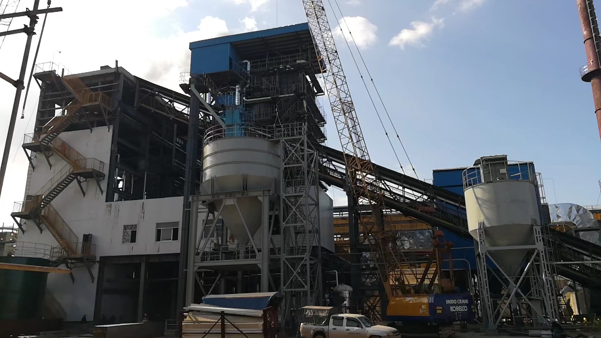
Instrumentation, Control System Configuration, and Interlock Verification for Safe Operation
Getting the control system right before you ever light a burner is, in my experience, the step most often compressed under schedule pressure — and the one that causes the most embarrassing forced outages in the first month of operation. CFB boilers are not forgiving of instrumentation gaps during startup. The combination of dense particle beds, fast-changing furnace pressures, and refractory that takes hours to thermally stabilize means a missing transmitter or a misconfigured interlock can turn a routine startup into a refractory repair job.
Critical Measurement Points During Startup
Bed temperature monitoring needs at minimum four thermocouple points per bed section, spread laterally — not clustered near the ignition burners. A single thermocouple reads one spot; the actual bed can have 80–120°C temperature gradients across its width during early ignition, especially if the fluidizing air distribution plate has uneven wear or partial blockage. Missing that gradient has led to localized overheating and clinker formation before operators realized the bed was stratifying.
Windbox pressure transmitters confirm that fluidizing air is actually reaching the bed — not just that the fan is running. Furnace pressure transmitters should be redundant (typically two or three voting), because a single-point failure during the negative-pressure furnace upset of a rapid load change can trip the boiler unnecessarily or, worse, fail to trip it when it should. Drum level on a steam-generating CFB needs three-element control from first steam production onward: steam flow, feedwater flow, and drum level together, not just level alone. Single-element control during low-load startup is a known cause of level excursions when steam demand suddenly shifts.
Flue gas O₂ and CO analyzers at the economizer outlet are non-negotiable for startup combustion quality. During the low-load coal introduction phase, CO spikes routinely hit 500–2,000 ppm as the bed temperature is still climbing through 700–800°C — this is expected, but it needs to be visible to the operator in real time, not inferred from a lagging O₂ reading. Solids return leg temperature at the loop seal or J-valve also deserves a dedicated point; a sudden drop there during startup usually signals a seal failure or loss of solids circulation before the main furnace pressure transmitters catch it.
Permissive Logic Versus Protective Logic
These are two fundamentally different things, and operators who conflate them make poor decisions under pressure. Permissive interlocks are the “may proceed” gates — a startup stage will not advance until conditions are met (bed temperature above 650°C before coal feed, for instance). Protective interlocks are the “must stop” trips — they act regardless of operator intent if a dangerous condition is detected. During a DCS-guided startup, operators sometimes bypass a permissive that seems overly conservative without realizing they are also bypassing the monitoring path for a related protective. Good DCS configuration keeps these logically and visually separate in the HMI.
Standard full-load PID tuning for fuel-air ratio control will perform adequately during CFB startup ramp below 40% loadFalse
PID parameters optimized at full load typically have gain and integral settings tuned for the plant's steady-state response. At low load, process gain, thermal inertia, and mass flow dynamics differ substantially — the result is sluggish response or oscillation. Gain-scheduled PID or manual control mode is standard practice during the startup ramp phase below roughly 30–40% MCR.
Combustion Control Loop Behavior at Part Load
CFB bed temperature has a thermal lag of roughly 5–10 minutes between a fuel rate change and a measurable bed temperature response — longer in a larger furnace or a cold bed with high thermal mass. Operators trained on stoker or oil-fired boilers often react to a temperature reading rather than anticipating where the bed is heading. That reactive pattern leads to fuel overshooting: the operator adds coal because the bed looks cold, then 8 minutes later the bed is running hot and they pull back, creating an oscillation cycle that stresses the refractory and makes the combustion team look bad.
Modern CFB DCS platforms use feedforward fuel control — the fuel demand signal is calculated from the load setpoint trajectory, not just from the bed temperature error. The feedback PID then trims. During startup ramp below roughly 40% load, most experienced operators I’ve worked with prefer manual fuel control with the feedforward active but the PID loop in manual, switching to automatic above the point where the combustion response becomes predictable.
Interlock Function Testing
Every safety interlock must be individually function-tested before startup, using the plant’s formal bypass and test-key procedure. This is not optional and not a formality. Each test should produce a documented record: the interlock tag, the simulated input value, the expected output action, the observed output action, a pass/fail result, the tester’s name, and a signed confirmation that the bypass was removed and the interlock was restored to service. In practice, a CFB boiler with a full complement of interlocks might require 30–60 individual test records for a first commissioning — budget the time accordingly, typically one to two days for a thorough sweep.
Historian Configuration and Alarm Rationalization
Configure the DCS historian to log all startup and shutdown transients at 1-second resolution, not the default 5- or 10-second intervals used for steady-state operation. Bed temperature ramps, drum pressure excursions, and furnace pressure spikes during ignition are fast events; coarse logging misses the causation sequence and makes post-event analysis nearly useless.
Alarm rationalization deserves equal attention. A CFB startup typically generates dozens of low-priority nuisance alarms — temperature deviations during ramp, level alarms before drum pressure stabilizes, permissive not-satisfied alerts during intentional holds. If these are not pre-rationalized and suppressed during known startup phases, operators face an alarm flood that buries genuine warnings. The result is alarm fatigue: operators acknowledge everything reflexively and miss the one CO high alarm or the one drum level deviation that actually matters.
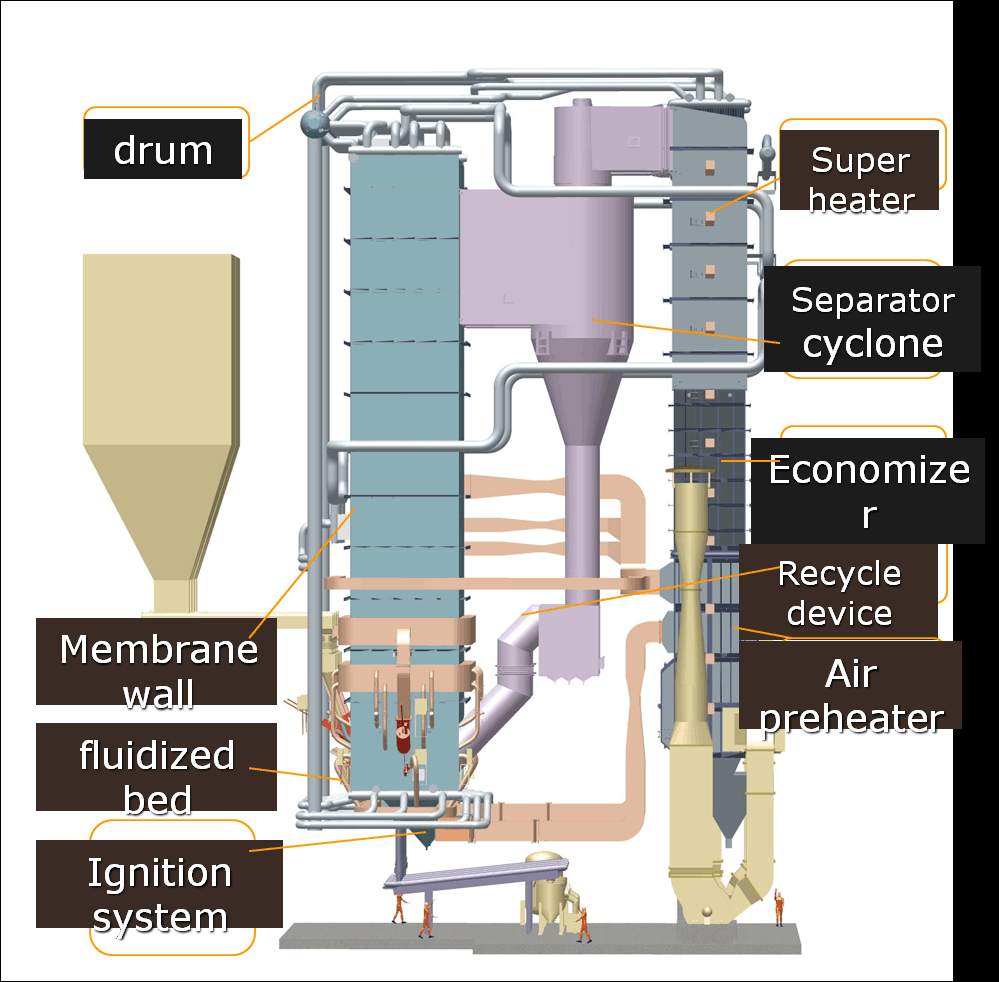
Common Operational Errors During CFB Startup and Shutdown — Root Causes and Corrective Actions
Procedural violations during CFB startup and shutdown account for a disproportionate share of unplanned outages, refractory failures, and — in the worst cases — furnace pressure excursions. Most of these errors aren’t caused by ignorance. They’re caused by time pressure, shift handover gaps, and the accumulated habit of “it worked last time.” The six patterns below are the ones that show up repeatedly in post-incident reviews and operator audits.
Premature Coal Introduction Before Bed Temperature Is Ready
This is probably the single most common and most dangerous startup error. Operators feel the pressure to get steam on the header and they push coal feed before the bed is genuinely at ignition temperature. At bed temperatures below roughly 650°C, coal volatiles release faster than they combust — CO builds in the furnace cavity, and if air flow fluctuates or a damper shifts, you have the conditions for a deflagration.
The corrective action is non-negotiable: the coal feeder start permissive must be hardwired to a minimum bed thermocouple reading of 650°C, preferably confirmed on at least two of the primary bed sensors, not just one. Software permissives alone are not sufficient here because they can be acknowledged or bypassed under shift pressure. Make it a hardwired interlock with a physical key override that requires shift supervisor sign-off and a log entry.
Coal feed initiated below 650°C bed temperature is a leading cause of CFB furnace CO deflagration events during startupTrue
At sub-ignition bed temperatures, volatile hydrocarbons from coal pyrolysis outpace combustion rates, allowing combustible gas accumulation; this is consistent with documented combustion engineering principles for fluidized bed systems and is why OEM startup manuals universally specify a minimum bed temperature permissive before solid fuel introduction.
Over-Ventilating During the 200–400°C Warm-Up Phase
Operators trying to manage CO readings during early warm-up instinctively open up combustion air. Makes sense intuitively. In practice, pushing air flow above minimum stable fluidization velocity during the 200–400°C refractory heating phase drives heat out of the bed faster than the refractory can absorb it uniformly, causing differential thermal expansion in the castable lining. You won’t see the cracks immediately — they show up three or four weeks later as spalling near the air distributor nozzle zone.
During this phase, target minimum fluidization velocity — typically 1.5–2.5 m/s at the bed, depending on particle size and bed depth — and hold it there. If CO climbs, the answer is to increase auxiliary burner output or slow the warm-up pace, not to flood the furnace with cold air.
Bypassing Drum Pressure Ramp Rate Limits on Hot Restart
Grid operators call. Plant managers call. The pressure to “just get it online” is real. But the drum and superheater headers carry residual differential stress from the trip, and if you ramp steam pressure faster than the OEM-specified 0.05–0.1 MPa/min, you’re accumulating thermal fatigue cycles that don’t show up as a visible problem today. They show up as stress corrosion cracking at header stub welds 18 to 36 months later, during a planned inspection that becomes an unplanned rebuild.
Establish a written plant rule — not a guideline, a rule — that startup ramp rate cannot be exceeded regardless of commercial pressure. Post it in the control room. Put it in the shift log template as a checkbox item.
Moisture in Bed Material After Extended Cold Standby
Bed material — typically silica sand, spent lime, or a mix — is hygroscopic enough that after 72-plus hours of cold shutdown with natural ventilation through the furnace, the surface moisture content can reach levels that cause flash steam evolution when bed reheat begins. The symptom is a sudden, unexplained pressure spike in the furnace during early warm-up, sometimes tripping the draft system interlocks.
Any shutdown exceeding roughly 72 hours should trigger a bed material dryness check. If the material has been sitting in a humid climate — Southeast Asia in monsoon season, coastal sites year-round — consider either pre-drying with low-flow warm air before ignition or replacing the top 150–200 mm of bed material with dry stock. It’s a minor operational step that prevents a confusing and potentially damaging trip during what should be a routine restart.
Skipping or Shortcutting the Pre-Ignition Furnace Purge After a Trip
After a short trip — say, a feeder fault that cleared in eight minutes — operators sometimes treat the purge cycle as a formality and bypass the timer to get back online quickly. This is one of the better-documented causes of furnace explosions in fluidized bed systems. Coal pyrolysis continues for several minutes after fuel feed stops; the volatile fraction can accumulate in dead zones near the cyclone inlet or secondary air ports where flow is low.
The purge interlock should be hardwired, not software-configurable from the operator station. Any trip-to-restart sequence shorter than the specified purge duration — typically 5 to 8 minutes at a minimum of 25–30% MCR air flow — should be physically impossible without a key-operated override that creates a written log entry. If your current DCS configuration allows a software bypass from the operator interface, that is worth fixing before the next startup.
Incorrect Ash Drain Sequencing During Shutdown
Opening ash drain valves before coal burnout is confirmed causes short-circuit air flow through the drain openings. The result is localized oxygen-deficient pockets — zones where bed material is hot but CO₂-depleted — where temperatures can spike unevenly and partial sintering begins. Bed material that has sintered into clinker around the drain manifold is a miserable maintenance problem: it means cold-end entry, mechanical breaking, and in some cases replacement of nozzles that were damaged by the thermal excursion.
The correct sequence is to confirm bed temperature is declining uniformly and fuel combustion is complete before opening any drain valve. In practice, this means waiting until the bed thermocouple array shows a consistent downward trend with no isolated hot zones — usually 20 to 40 minutes after coal feed cutoff, depending on bed depth and load at trip.
| Error | Root Cause Driver | Primary Consequence | Corrective Action |
|---|---|---|---|
| Early coal feed | Time pressure, soft permissive | CO accumulation, deflagration risk | Hardwired 650°C feeder permissive |
| Excess warm-up air | CO anxiety | Refractory spalling (delayed) | Hold minimum fluidization velocity 200–400°C |
| Ramp rate override | Commercial/grid pressure | Header stress corrosion cracking | Written plant rule, log checkpoint |
| Wet bed material | Standby without check | Furnace pressure spike on restart | 72-hour protocol: check or replace top bed layer |
| Purge bypass | Short trip, time pressure | Furnace explosion | Hardwired purge interlock, no soft bypass |
| Early ash drain opening | Poor sequence knowledge | Bed sintering, nozzle damage | Confirm burnout complete before any drain valve |
Maintenance Tasks Triggered by Startup and Shutdown Events: Integrating Procedures with Planned Outage Scheduling
Every controlled shutdown is a maintenance opportunity. That sounds obvious, but in practice, plants routinely bring a CFB boiler back online after a 12-hour outage having done nothing beyond a visual walkround — then wonder why they accumulate deferred maintenance until a forced outage forces their hand six months later. The discipline of tiered, duration-triggered inspection scopes is what separates a well-run plant from one that’s always firefighting.
Tiered Inspection Scope by Outage Duration
The minimum scope expands with outage length. An 8-hour window — the shortest worth planning around — should cover: ID/FD fan bearing temperature and vibration spot-check, expansion joint visual inspection, bed drain valve exercise (open/close cycle to confirm no seizure), feedwater control valve stem packing check, and a walk of the flue gas ducting for any visible ash bypass leaks. That’s it. Don’t try to do more; you’ll either rush it or delay restart.
At 24 hours, add: sieve analysis of a bed material sample (more on this below), fabric filter bag inspection for a 2–5% random sample, economizer access door inspection for tube fin fouling, and a review of the bearing vibration trend data logged since the last outage. If any bearing shows a rising trend over the last 3–4 operating cycles, this is the window to replace it — not wait for it to announce itself during a load ramp at 3 a.m.
A 72-hour outage allows drum internal access once pressure is fully relieved, cyclone refractory wear measurement, air preheater element inspection for plugging (ash-side), and full actuator stroke testing across the fuel feed and air damper systems. The air preheater plugging check is frequently skipped; in my experience it’s one of the more common contributors to poor air distribution on restart, especially after burning fuels with higher alkali content.
Two-week planned outages are where you address anything requiring refractory patch repair, tube thickness measurements on high-wear zones, complete rotating equipment overhauls, and full DCS interlock logic verification against the current set-point list. Don’t wait for a two-weeker to discover the interlock set points have drifted from commissioning values — that should have been caught at the 72-hour level — but use the longer window for the systematic audit.
Bed Material Condition After Major Shutdowns
Pull a bed drain sample after every shutdown lasting more than 24 hours. Sieve it. If the median particle diameter has shifted more than roughly 20% from the design specification — typically 0.2–0.4 mm for most coal-fired CFB designs, though this depends on fuel type and cyclone cut size — you’re looking at degraded fluidization quality and uneven combustion on the next startup. Agglomeration is the more urgent finding: sintered clusters in the sample indicate the bed approached or briefly exceeded the ash softening temperature, which correlates with inadequate temperature monitoring or a bed temperature excursion during the previous run. Replace the bed material rather than restart on compromised inventory.
Waterside Inspection and Chemistry Correlation
Cold shutdowns with drum pressure fully relieved create the only practical window for drum internal inspection. Look for scale thickness, pitting patterns, and any deposition character that’s changed since the last inspection. Cross-reference what you find against the feedwater chemistry logs — if silica or iron levels have been running high and you’re now seeing corresponding deposition, adjust the treatment program before the next startup, not after another cycle has compounded the problem.
Replacing bed material when median particle diameter deviates more than 20% from design specification restores fluidization uniformity and reduces the risk of localized hotspots during the next startup.True
CFB fluidization quality is sensitive to particle size distribution; coarsened or agglomerated bed media requires higher air velocity to achieve minimum fluidization velocity, which can create uneven bed temperature profiles and combustion instability during early load ramp stages.
Rotating Equipment: Trend Review, Not Just Spot Checks
A single vibration reading at shutdown tells you little. The value is in the trend across multiple shutdowns. Set up your CMMS — or even a simple spreadsheet if that’s what’s available — to plot bearing vibration amplitude per machine per outage event. A bearing showing a 15–20% rise in peak velocity over three consecutive cycles is a candidate for outage replacement. Waiting for it to fail during operation almost always means collateral damage: shaft scoring, housing damage, sometimes seal failure, and an unplanned outage at the worst possible time.
EPC Handover Documentation and Ongoing Support
For CFB projects delivered under EPC scope, the handover package plant operators actually need is more specific than what’s typically described in a contract schedule. At minimum it should include: the startup and shutdown procedure manual keyed to the specific unit configuration (not a generic OEM document), the maintenance schedule structured around the tiered outage windows described above, the full interlock set-point list as-commissioned with any site-specific deviations noted, and direct technical support contacts with guaranteed response times covering at least the first two years of operation. Remote diagnostic capability — where the engineering team can review DCS trend data during a difficult startup or unusual trip event — has real value and saves travel cost on projects where the plant is far from the manufacturer’s base. Plants that use this support channel systematically tend to resolve startup anomalies faster and accumulate better operating data for future outage planning.
Frequently Asked Questions About CFB Boiler Startup and Shutdown Procedures
How long does a cold startup take, and what makes it longer?
For an established plant with cured refractory, cold startup typically runs 4–8 hours from ambient to full load. That range depends on drum pressure class (a 9.8 MPa unit ramps more cautiously than a 1.6 MPa one), the capacity of your auxiliary burner system, and how aggressively your OEM permits the pressure ramp — usually 0.05–0.1 MPa/min, though some drum designs allow slightly faster.
New units are a different story entirely. First-time refractory dry-out demands 72–120 hours of controlled heating across multiple temperature holds, following a cure curve the refractory supplier specifies for the castable type used in the furnace, cyclone, and loop seal. Skip a hold or rush a ramp and you’ll hear it — audible cracking — and the resulting spalls can block nozzles or migrate into bed drain lines. That repair cost easily runs into several days of unplanned downtime plus materials and hot-work labor. Don’t let schedule pressure compress the dry-out curve.
Can you start a CFB boiler on coal alone, without auxiliary ignition fuel?
No. Coal does not self-ignite reliably at cold bed temperatures; its auto-ignition temperature in a fluidized environment is effectively reached only above roughly 600–700°C depending on coal rank and volatiles content. You need oil or gas burners to raise the bed to 550–650°C before coal feed begins. Introducing coal into a cold or barely warm bed risks unburned coal accumulation — a furnace explosion hazard that no procedure document should allow you to shortcut.
Some modern CFB designs do incorporate plasma ignition systems, which reduce auxiliary fuel consumption substantially. In practice they lower oil use by perhaps 60–80% on a startup event, but they do not eliminate the need to reach the threshold bed temperature before coal is admitted. They’re worth the capital cost on units doing frequent starts, less so on baseload plant doing two or three cold starts a year.
Coal feed into a CFB boiler can begin safely below 600°C bed temperature if volatile content is high enough.False
Regardless of coal rank, industry practice and OEM interlock logic require bed temperature to reach at least 650°C before initiating coal feed, specifically to prevent unburned fuel accumulation and the deflagration risk it creates.
What is the minimum stable load, and why does it matter operationally?
Typical minimum stable load for a CFB boiler sits at 25–30% of MCR, though some well-tuned units with good air distribution can hold closer to 20%. Below that threshold, bed temperature starts drifting downward — you lose combustion stability, limestone injection becomes ineffective for SO₂ capture because the calcination kinetics slow, and solids circulation through the cyclone thins to the point where the loop seal risks defluidizing.
For grid-connected power plants, this threshold defines your operational floor during low-demand periods. If the grid dispatch curve drops below it, you’re either banking the bed with auxiliary fuel support or shutting down — neither is free.
What happens to the refractory after an emergency shutdown where controlled cooldown wasn’t possible?
You cannot assume it’s fine. Post-trip, once the unit is confirmed safe and cool enough for entry (typically below 50°C at inspection points), conduct a visual inspection of the cyclone inlet, loop seal crown, and furnace upper zone. Look for crack patterns wider than about 2–3 mm or any spalled sections larger than roughly a palm. Minor hairline cracking in the refractory face coat is common after a thermal shock event and can often be monitored through the next cycle rather than repaired immediately — but document it with photographs and add it to the pre-startup checklist for next restart.
If you find structural spalls or cracks penetrating into the insulating layer, repair before restart. Temporary ceramic fiber blanket applied externally over suspected weak zones can slow further damage while you await repair materials, though this is a short-term measure only. The risk-based decision is simple: a monitored crack costs you vigilance; a collapsed section during operation can cost you the unit.
How does a CFB startup procedure differ from a BFB boiler startup?
The bubbling fluidized bed boiler has no external solids circulation loop — no cyclone, no return leg, no loop seal. CFB startup requires you to commission all of that before declaring the unit stable. The loop seal fluidization air must be confirmed before bed material returns from the cyclone; if you get that sequence wrong, you get a plug of solids sitting in the downcomer with nowhere to go. CFB furnaces are also taller, which means steeper vertical temperature gradients during the early heat-up phase — the upper furnace and cyclone refractory are cold while the bed is approaching ignition temperature, so you’re managing a much larger thermal mass spread over more volume. BFB startup is genuinely simpler. CFB makes up for it with fuel flexibility and turndown.
How does Taishan Group support overseas clients through first startup and commissioning?
Commissioning engineers are dispatched to site, typically arriving before mechanical completion to review the installation against the engineering drawings before anything is fired. Startup procedure documentation is provided in English. For projects on DCS platforms with remote connectivity, our engineers can monitor key process variables — bed temperature profile, drum level, air flow distribution — from the factory during the critical first-light sequence, which has proven useful on projects where site communication is difficult. Operator training covers both normal procedures and emergency response, and is conducted in English with client interpreters where needed. The EPC warranty package includes startup support through the performance test period, so the commercial handover is tied to demonstrated, stable operation rather than just first fire.
What emission monitoring applies during startup, and is there a regulatory grace period?
Requirements vary by jurisdiction, but the trend globally is toward tighter startup allowances. In the EU Industrial Emissions Directive framework, startup and shutdown periods can be excluded from compliance averaging only under defined conditions, and the window is short. In many Southeast Asian and Middle Eastern jurisdictions where CFB units are commonly installed, the regulator may allow a transient period — often 4–8 hours — during which flue gas opacity and SO₂ exceedances are not counted against the permit, provided CEMS is operational and logging.
CEMS calibration must be completed and certified before commercial operation is declared. During startup, CO in particular spikes during the early coal feed phase as combustion stabilizes; NOx is typically low early and rises with bed temperature. Plan your startup schedule so the transition through the high-CO phase happens during daylight when your stack is visible and your environmental team is on-site. It’s a small thing, but regulators notice a lot less if opacity is visible at 2 PM on a Tuesday than at 2 AM.
References
- BPVC Section VII — Recommended Guidelines for the Care of Power Boilers — ASME
- NFPA 85 — Boiler and Combustion Systems Hazards Code — National Fire Protection Association
- Annual Reminder for Restart of Boilers — Startup Checks and Safe Starting Sequence — National Board of Boiler and Pressure Vessel Inspectors
- Boiler Logs Can Reduce Accidents — Operating and Maintenance Records — National Board of Boiler and Pressure Vessel Inspectors
- Valmet CFB Boiler — Circulating Fluidized Bed Technology — Valmet
- PowerFluid Circulating Fluidized Bed Boilers — ANDRITZ
- Industrial and Utility Plant Boiler Services — Operation and Maintenance — GE Vernova
- PTC 4 — Fired Steam Generators: Performance Testing — ASME
- Boiler Efficiency and Combustion — Air Supply and Combustion Control — Spirax Sarco
- Water for the Boiler — Feedwater Treatment and Boiler Water Chemistry — Spirax Sarco