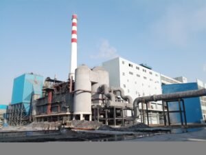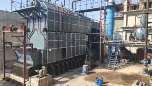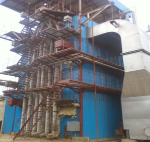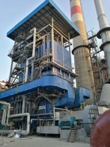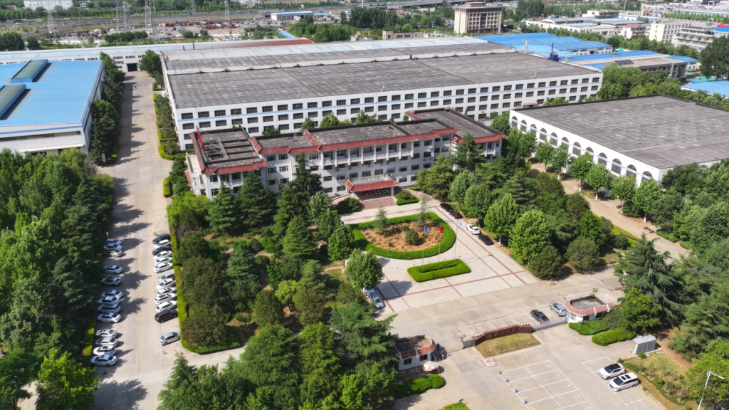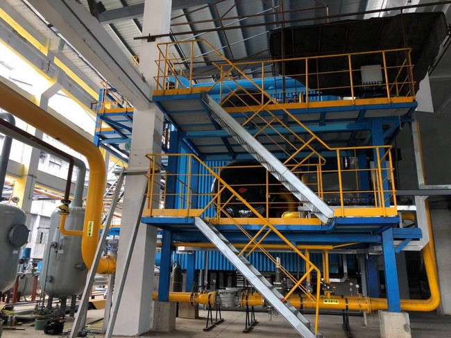
When a boiler, turbine, and condenser are specified, purchased, or operated as if they were three separate machines rather than one tightly coupled thermodynamic system, the consequences show up fast — unstable steam conditions that force turbine de-rating, condenser hotwell temperatures that creep up through summer and clip output by 3–8%, boiler pressure swings that trigger safety trips and leave the plant in an unplanned cold start that can cost a day or more of lost generation. The root problem is almost always integration: mismatched design points, poorly commissioned control handshakes, or a condenser sized for a climate that no longer applies.
A power plant boiler integrates with the turbine generator and condenser through a closed thermodynamic loop: the boiler produces high-pressure, high-temperature steam that expands through the turbine to generate electricity, exhausts into the condenser where it is returned to liquid, and is pumped back to the boiler as feedwater. Every pressure, temperature, and flow setpoint in the system is interdependent — a change at the condenser shifts turbine backpressure, which alters boiler steam demand, which affects combustion load and drum pressure.
What makes this harder than textbook thermodynamics suggests is that the interdependencies are not static. Fuel quality shifts seasonally, cooling water temperature rises in summer, turbine blade clearances open up with operating hours, and boiler tube fouling creeps in over months. Each of those changes nudges the system’s equilibrium point. Understanding exactly how the steam path connects these three components — and where the design assumptions can drift against you — is what separates a plant that runs at 91% availability from one that spends its life chasing alarms.
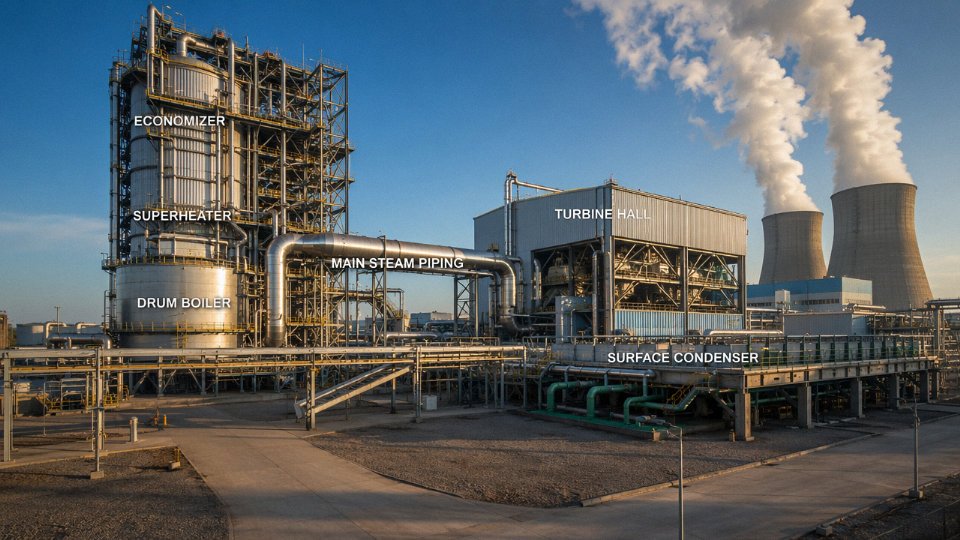
Boiler Steam Outlet to Turbine Inlet: Matching Pressure, Temperature, and Flow Specifications
The interface between the boiler steam outlet and the turbine stop valve is, in practical terms, a binding contract. Before a single weld is made, the boiler manufacturer and the turbine OEM must agree on four numbers: main steam pressure, main steam temperature, mass flow rate at rated load, and minimum superheat margin. Every component between the drum and the first turbine stage exists to honor that contract under all operating conditions — startup, full load, partial load, and trip.
For subcritical industrial power boilers, main steam conditions typically fall in the range of 9.8–13.7 MPa and 510–540°C, depending on unit size and the turbine inlet card the OEM provides. Supercritical and ultra-supercritical units push that to 24–31 MPa and 560–620°C at the turbine flange. The mass flow rate — usually expressed in t/h — is what actually sizes the boiler’s evaporator, superheater surface area, and feedwater pump. Get that number wrong by even 5–8%, and you’re either starving the turbine or running the boiler with inadequate steam velocity through superheater tubes, which causes localized overheating and creep damage over time.
Taishan boilers are rated to match turbine inlet specifications from major turbine suppliers, which means the design package always includes a verified steam condition guarantee at the main steam outlet flange — not at the drum, not somewhere upstream of the attemperators. That distinction matters on site.
Main Steam Line Components and Their Protective Roles
Between the superheater outlet header and the turbine stop valve, you’ll find a sequence of equipment that is easy to underestimate during procurement. The main steam stop valves (MSVs) isolate the turbine on trip; they need to close in under two seconds and must be spec’d for the full operating temperature and pressure. Downstream, the turbine control valves regulate steam admission and handle load-following — these are precision items and their cv characteristics need to match the boiler’s response curve.
Spray desuperheaters (attemperators) are installed in the superheater circuit to trim steam temperature before it reaches the turbine. In practice, boilers rarely hit the exact design temperature across the full load range — combustion conditions change with fuel quality, ambient temperature, and fouling on heat transfer surfaces. The attemperator gives the control system roughly 20–40°C of adjustment range, using demineralized feedwater as the spray medium. Undersizing these stations is a common mistake in EPC projects and shows up as temperature excursions during load swings.
Steam Quality and Turbine Blade Life
Steam quality at the turbine inlet is non-negotiable. Wet steam — even a dryness fraction of 0.98 — carries liquid droplets that erode first-stage blades at high velocity. The damage is cumulative and not immediately visible, but a plant running systematically low on superheat margin will find itself pulling the HP turbine rotor for blade replacement several years ahead of schedule. On the other end, excessive superheat beyond the turbine OEM’s rated inlet temperature accelerates creep in rotor and casing materials. The target band is typically ±5°C of the rated inlet temperature, maintained continuously.
Reheat Circuit: Restoring Energy to Partially Expanded Steam
In two-stage (HP/IP) turbine configurations, steam exhausting from the HP turbine is typically at 3.0–5.0 MPa and has cooled to roughly 300–340°C by the time it returns to the boiler reheater inlet. The reheater restores that steam to 540–570°C before it enters the intermediate-pressure turbine — a temperature lift of 200–260°C across the reheater surface. This step improves cycle efficiency meaningfully and, just as usefully, keeps the steam dry enough through the later turbine stages to protect LP blades from moisture erosion.
The hot reheat line runs at lower pressure than the main steam line, but at comparable temperature, which means the material requirements are essentially the same. Both hot reheat and main steam lines in supercritical units use P91 (9Cr-1Mo-V) chrome-moly alloy pipe as standard — it holds creep strength up to around 600°C in sustained service. P22 is sometimes used in subcritical applications where temperatures stay below 565°C, but the trend in new projects is toward P91 throughout, partly for standardization of welding procedures and partly because the safety margin is worth it.
Coordinated Boiler-Turbine Control and Thermal Expansion
The boiler’s combustion control system — fuel feed, air-fuel ratio, drum level — doesn’t operate independently of the turbine. In a coordinated boiler-turbine (CB/T) master control scheme, the turbine control valves and the boiler firing rate work together to match load demand signals. The turbine responds fast (seconds); the boiler responds slowly (minutes). That mismatch is managed through pressure setpoint scheduling and drum level correction, and if the control logic is tuned poorly, you’ll see pressure oscillations that stress the superheater headers on every load change.
Piping thermal expansion is an EPC detail that sometimes gets underestimated until the first hot commissioning run. A 100-meter run of main steam pipe at 540°C expands roughly 70–90 mm relative to its cold position. Support hangers, spring cans, and expansion loops need to be designed and installed to accommodate that movement without imposing nozzle loads on the turbine casing that exceed the OEM’s allowable limits — exceeding those limits is one of the faster ways to crack a turbine casing flange.
P91 chrome-moly alloy is the standard pipe material for main steam and hot reheat lines in supercritical power boilersTrue
P91 (Grade 91, 9Cr-1Mo-V) is widely specified by boiler and piping engineers for high-temperature steam service above roughly 540°C due to its superior creep resistance compared to P22, and is referenced in ASME B31.1 and equivalent international codes for power piping in this temperature range.
Turbine Exhaust to Condenser: Back-Pressure Management and Exhaust Steam Ducting
The interface between the low-pressure (LP) turbine exhaust and the condenser inlet is, in practice, where a surprising amount of plant output quietly disappears — or gets recovered. It is less glamorous than the main steam line, but operationally it is the most sensitive coupling in the entire cycle.
What Back-Pressure Actually Means and Why It Costs You Power
Condenser back-pressure is simply the absolute pressure at the LP turbine exhaust flange — the pressure the steam is expanding toward. In a well-maintained plant with adequate cooling, this sits somewhere between 4 and 8 kPa absolute under normal summer operating conditions; in cold climates with cooling towers or once-through river water in winter, you can see it dip to 3–4 kPa, which is genuinely beneficial.
Every 1 kPa rise in back-pressure costs roughly 0.3–0.5% of turbine output — the exact figure depends on turbine design, load, and where on the LP expansion line you are operating. For a 50 MW industrial condensing turbine running at full load, 1 kPa of additional back-pressure translates to somewhere around 150–250 kW of lost output. That is not catastrophic in isolation, but a condenser that has drifted from 5 kPa to 8 kPa over a fouled summer — which happens more often than anyone likes to admit — is costing that unit 450–750 kW continuously. At $0.07–0.10/kWh, you are looking at $25,000–$55,000 per month in unrealized generation. The numbers depend heavily on electricity pricing and annual operating hours, but the direction never changes.
A 1 kPa increase in condenser back-pressure reduces turbine heat rate by approximately 0.3–0.5% at full load conditions.True
This is a well-established thermodynamic relationship in steam turbine engineering, consistent with published heat rate correction curves from major turbine OEMs and confirmed by plant performance testing standards such as ASME PTC 6.
Exhaust Hood, Expansion Joints, and the Condenser Neck
The LP turbine exhaust hood — the large diffuser section bolted above or beside the condenser — has to handle steam volumes that are orders of magnitude larger than the HP inlet, because the specific volume of steam at 5 kPa is enormous compared to high-pressure steam. Last-stage blades on large industrial turbines can be 400–900 mm long depending on rating; the exhaust annulus is designed to minimize leaving losses, and any back-pressure above the design point forces the blades to operate in a regime they were not optimized for.
The connection between the exhaust hood and the condenser inlet neck uses a large flexible expansion joint — typically a fabric or metallic bellows type, sized to absorb 20–60 mm of thermal differential movement axially and several millimetres laterally. Getting this joint wrong, or allowing it to degrade, introduces two problems simultaneously: vibration transmission from turbine to condenser (damaging to condenser tube sheets) and air in-leakage, which is covered below.
Cooling Systems and Seasonal Back-Pressure Variation
Once-through cooling — drawing water directly from a river, lake, or sea — gives the most stable and typically the lowest condenser pressure, because inlet water temperature is more predictable and there is no evaporative concentration to manage. The downside is regulatory and geographic: discharge thermal limits, intake screening requirements, and the obvious constraint that you need to be near sufficient water. Seasonal variation still exists; a coastal plant in a temperate climate might see cooling water swing from 8°C in February to 28°C in August, shifting condenser pressure by 3–5 kPa across the year. That seasonal swing directly affects your capacity factor and dispatch economics.
Recirculating systems with cooling towers decouple the plant from a water body but introduce their own back-pressure instability. In high wet-bulb temperature conditions — humid summer afternoons — cooling tower performance degrades, approach temperatures rise, and condenser pressure climbs. Plants in subtropical climates routinely see summer condenser pressures 2–4 kPa higher than winter values. You design the condenser for the worst case; you accept that the turbine runs slightly below nameplate for several months a year. The alternative — oversizing the cooling tower — has a capital cost that usually does not pencil out unless the plant has a very aggressive dispatch profile.
Air In-Leakage: The Silent Vacuum Killer
Air does not condense. Any non-condensable gas that enters the condenser shell accumulates at the cold end, blankets tube surfaces, and suppresses vacuum. Even a small air in-leakage rate — say, 5–10 kg/h on a mid-size unit — can raise back-pressure by 0.5–1.5 kPa if the vacuum extraction system cannot keep up.
Sources are everywhere: valve stem packing on LP turbine extraction lines, the expansion joint itself, instrumentation penetrations, LP feed heater vents, and any threaded fitting that lives in a vacuum environment. The frustrating part is that these leaks are almost impossible to find by visual inspection.
The standard detection approach is helium leak testing: flood a suspected zone with helium from a small cylinder, then monitor a mass spectrometer probe at the vacuum pump discharge. It is fast, sensitive down to very small leak rates, and does not require shutdown. For a rough quantitative check, a vacuum decay test — isolating the condenser from the steam supply and measuring pressure rise rate over a fixed interval — gives you a single number that you can trend over time to catch deteriorating joints before they become serious.
Steam jet air ejectors (SJAEs) were the traditional vacuum extraction device and are still common on older plant and in industrial-scale units where motive steam is cheap. Liquid ring vacuum pumps have largely replaced them in newer designs because they consume less energy and do not require a constant steam supply during low-load operation. In practice, having a standby unit — either a second SJAE stage or a backup pump — is not optional if you are running a plant that sells power commercially.
Tube Fouling and Online Cleaning
Condenser tubes foul from three main mechanisms: biological growth (particularly in once-through seawater or river water systems), mineral scaling (calcium carbonate, silica — worse in recirculating systems as cycles of concentration rise), and sediment deposition in low-velocity areas. All three reduce the overall heat transfer coefficient U, and the relationship between U and back-pressure is not linear — the first 10–15% reduction in U might cost you 0.5 kPa; the next 10% costs more because you are already operating at a degraded point on the cooling curve.
A condenser where U has dropped 20% from its clean condition — which is not unusual after a long operating season without cleaning — typically shows 1–3 kPa of back-pressure increase, again depending on cooling water temperature and flow rate. Online tube cleaning systems, which circulate slightly oversized sponge balls through the tubes continuously, can hold U within a few percent of the clean-tube value. The payback on these systems is usually well under two years on a unit of any meaningful size.
Back-Pressure Turbines in Industrial CHP: A Different Logic Entirely
Not every boiler-turbine integration ends at a condenser. In industrial cogeneration — district heating networks, process steam supply for chemical or food plants, paper mills — the LP turbine exhausts directly into a process steam header, typically at 0.3–1.2 MPa absolute. There is no condenser, no vacuum system, no cooling tower. The “back-pressure” in this context is set by the process load, not by a heat sink.
This changes the integration logic substantially. The boiler must supply steam at a pressure and temperature that satisfies both the turbine’s inlet requirements and the process’s demand at the exhaust end. Load swings on the process side translate directly into turbine operating point changes, which feed back to boiler firing rate. Control coordination between the boiler’s combustion management system and the turbine governor is tighter and more immediate than in a pure condensing plant.
Taishan industrial boilers — particularly our biomass, coal-fired, and gas-fired steam boilers in the 10–130 t/h range — are routinely configured as the steam source for back-pressure turbine-generator sets in exactly these CHP applications. The combination of a well-matched boiler and a back-pressure turbine can push overall fuel utilization to 75–85%, compared to 38–47% for a condensing power plant, because you are extracting work and delivering usable heat rather than rejecting it through a cooling tower. Whether that tradeoff makes sense depends entirely on whether you have a reliable heat load — a process that runs year-round and cannot tolerate steam interruptions. If the heat load is seasonal or uncertain, the economics get complicated quickly.
Feedwater System: Condensate Recovery, Deaeration, and High-Pressure Preheating Before the Boiler
The feedwater circuit is where most operators stop paying close attention — and where a surprising share of boiler damage actually originates. Steam leaves the turbine, condenses in the condenser, and the resulting condensate has to travel through six or seven distinct process stages before it re-enters the boiler as acceptably clean, oxygen-free, preheated feedwater. Each stage matters.
Condensate Path from Hotwell to Economizer Inlet
Condensate collects in the condenser hotwell at roughly 30–50°C, depending on condenser vacuum and cooling water temperature. The condensate extraction pump (CEP) lifts it out of the hotwell against a relatively modest pressure, typically 1–3 MPa at the CEP discharge, and pushes it through a train of low-pressure feedwater heaters (LP heaters). These are shell-and-tube exchangers fed with extraction steam bled from the LP turbine stages. In a six-to-eight heater cycle — common in 100 MW and larger units — the LP heater train raises condensate temperature progressively to somewhere in the 130–175°C range, depending on the number of extraction points and the turbine’s stage pressure profile.
The deaerator sits at roughly the midpoint of this train and deserves its own discussion.
Deaeration: Why Sub-7 ppb Oxygen Is Not Optional
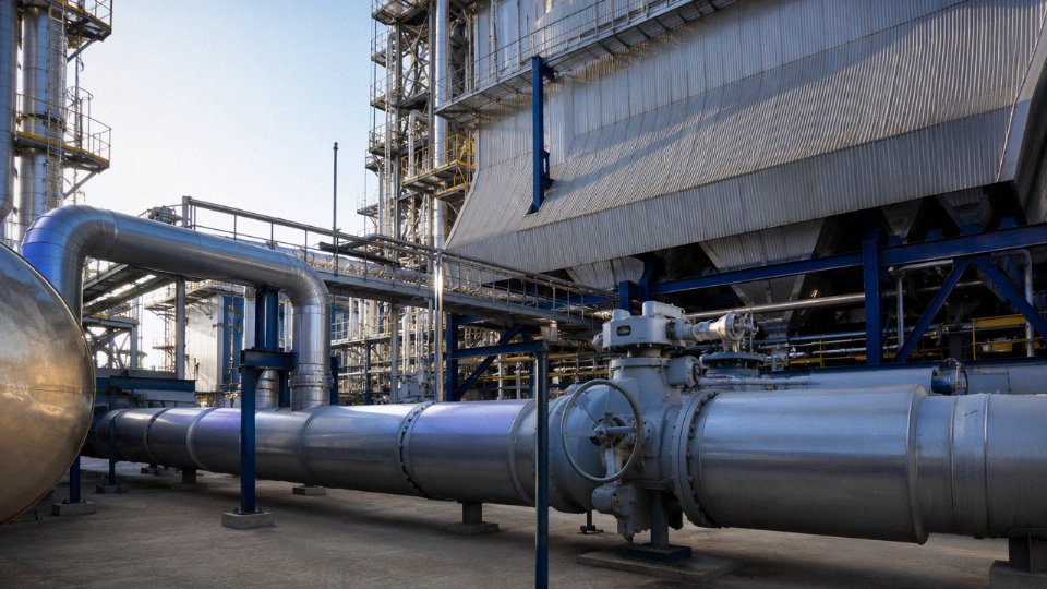
Dissolved oxygen above roughly 7 ppb and any meaningful CO₂ concentration will corrode boiler tubes from the inside — slowly at first, then faster as pitting concentrates stress. A single oxygen excursion during startup, if the deaerator hasn’t been given enough time to stabilize, can initiate pitting that becomes a tube failure six or eighteen months later. The deaerator uses heating steam extracted from an intermediate turbine stage, typically at 0.3–0.8 MPa, to heat the condensate to saturation temperature and physically strip dissolved gases. The combination of heating to saturation (eliminating the solubility advantage for O₂ and CO₂) and mechanical spray/tray stripping gets oxygen down to the required range. A deaerator running cold — say, because extraction steam pressure dropped and nobody noticed — will pass elevated oxygen straight to the boiler feed pump suction.
Regenerative Heating: The Efficiency Payoff
After the deaerator, the boiler feed pump (BFP) compresses feedwater from deaerator pressure up to full boiler operating pressure — often 15–32 MPa in supercritical and ultra-supercritical units. The compressed feedwater then passes through high-pressure (HP) feedwater heaters, again using extraction steam, now from the HP turbine extraction points. The thermal logic is elegant: energy that would otherwise be thrown away in the condenser is instead used to preheat feedwater. Each 10°C rise in feedwater temperature entering the economizer saves roughly 0.25–0.35% in fuel consumption, with the exact figure depending on fuel type, boiler pressure, and cycle configuration. Across a 300 MW unit running 7,000–7,500 hours a year, that adds up.
Each 10°C increase in feedwater temperature from regenerative heating saves approximately 0.25–0.35% in boiler fuel consumptionTrue
This follows from standard Rankine cycle thermodynamics: replacing heat addition at low temperature (in the boiler furnace) with heat recovery from turbine extraction steam reduces the heat input required per unit of steam generated. The range reflects variation across pressure levels, fuel types, and cycle configurations.
Feedwater Quality: Different Rules for Drum vs. Once-Through Boilers
Drum boilers tolerate somewhat higher TDS — typically up to 200–500 µS/cm in the drum water, depending on operating pressure — because blowdown removes concentrated impurities continuously. Subcritical drum units at 9.8–18.3 MPa generally require feedwater conductivity below 0.3 µS/cm, silica under 20 ppb, hardness effectively zero, and pH in the 8.8–9.3 range for all-ferrous systems. Once-through supercritical boilers are less forgiving: there’s no drum to act as a buffer, so silica must be under 10 ppb, iron under 10 ppb, and conductivity at the economizer inlet is often held below 0.1 µS/cm. Achieving that requires a full water treatment train: clarification, softening or ultrafiltration, reverse osmosis, and mixed-bed demineralization for makeup water, plus a polishing condenser demineralizer on the condensate return to catch resin fines and ingress from condenser tube leaks. A small seawater-cooled condenser with a few tubes weeping can contaminate the feedwater within hours.
Drum Level Control: Three-Element Logic as a Safety Boundary
Drum level control — the three-element scheme watching drum level, steam flow, and feedwater flow simultaneously — is one of those things that looks straightforward on a P&ID and causes real trouble when it isn’t tuned right. Too little water and you burn furnace tubes. Too much and you carry water droplets into the steam line and hammer the turbine. The three-element controller compares steam flow demand against feedwater flow and adjusts the feedwater control valve, while drum level provides the trim correction. During rapid load swings, “swell” (drum level rising briefly as steam bubbles form faster) can fool a single-element controller into cutting feedwater exactly when it should be increasing. Plants running frequent load following cycles need this tuned carefully and checked after every major control system maintenance.
The Boiler Feed Pump: The Plant’s Biggest Auxiliary Load
The BFP is typically the single largest auxiliary power consumer in the plant — usually consuming 1–3% of gross generator output, which on a 300 MW unit is somewhere around 3–9 MW depending on operating pressure and flow. Motor-driven BFPs (MDBFPs) are simpler and easier to start, but they draw from the station electrical system. A turbine-driven BFP (TDBFP), driven by a small back-pressure or condensing steam turbine fed from the main turbine extraction, reduces the electrical auxiliary load and can improve net plant output by 0.5–1.5 percentage points — meaningful at the scale of utility operation. The tradeoff is added mechanical complexity, an additional steam extraction tap, and a longer startup sequence. Most large supercritical units use a TDBFP as the running pump with a motor-driven standby. Smaller industrial power plants, roughly 50 MW and below, often just use MDBFPs throughout and accept the auxiliary load penalty.
Boiler Type Selection for Power Generation: CFB, Pulverized Coal, Biomass, and Waste-to-Energy Configurations
Choosing the right boiler technology is arguably the most consequential decision in a power project. Get it wrong and you are either burning money on fuel conditioning, fighting emissions limits with expensive add-on systems, or watching availability drop because the boiler was never designed for the fuel you are actually burning. The selection is driven by four things: fuel type and variability, required steam parameters, plant capacity, and the emission standards of the host country.
CFB vs. Pulverized Coal: Efficiency vs. Fuel Flexibility
Pulverized coal (PC) boilers dominate at large scale — typically above 200–300 MW — because the fine grinding and high combustion intensity push thermal efficiencies toward the upper end of what the steam cycle allows. Supercritical PC units routinely hit boiler efficiencies of 91–94% (LHV basis). At that scale, even a 1–2% efficiency gain compounds into serious fuel cost savings over a 30-year asset life.
Below roughly 150–200 MW, or wherever the fuel supply is mixed or low-grade, a circulating fluidized bed (CFB) boiler is usually the more practical choice. CFB combustion temperature sits at 850–950°C, which suppresses thermal NOx formation without SCR in most cases, and in-furnace limestone injection handles SO₂ at reasonable Ca/S ratios — often achieving 70–90% SO₂ capture without a wet flue gas desulfurization system. That matters a great deal in markets where FGD capital cost or reagent supply is a real constraint. CFB units also tolerate fuel moisture up to roughly 40–45% and heating values as low as 10–12 MJ/kg, which opens the door to low-rank coal, coal slurry, washery rejects, and biomass co-firing in the same furnace.
Biomass-Fired Power Boilers: The Corrosion Problem Nobody Warns You About Enough
Biomass fuels look attractive on paper — carbon-neutral, often cheap — but the fuel variability is brutal in practice. Moisture content swings from 15% in seasoned wood chips to over 50% in fresh agricultural residues, and the lower heating value follows, ranging roughly 8–17 MJ/kg depending on species, season, and storage. That range forces the combustion control system to work hard just to hold steady steam conditions.
The more serious problem is superheater corrosion. Straw, rice husk, and similar agricultural residues carry chlorine and alkali compounds (mainly potassium chloride and potassium sulfate) that deposit on superheater tubes and drive corrosion rates that can consume standard carbon steel in under two years. The practical response is two-fold: limit live steam temperature to roughly 450–520°C in straw-dominated fuel mixes rather than pushing for higher cycle efficiency, and specify alloy tubing — typically TP347H or Inconel-clad tubes in the high-temperature superheater zones — where alkali chloride attack is worst. Grate-fired configurations suit lower-capacity biomass plants (roughly 10–75 t/h steam), while CFB scales better above that and handles fuel inconsistency more gracefully.
Biomass boilers using chlorine-rich agricultural residues require superheater alloy upgrades beyond standard carbon steel to achieve acceptable tube service lifeTrue
Alkali chloride compounds in straw and rice husk cause accelerated high-temperature corrosion on superheater surfaces; this is well-documented in biomass combustion engineering literature and reflected in boiler design standards for agricultural residue fuels.
Waste-to-Energy Boilers: Living With the Corrosion-Efficiency Tradeoff
Municipal solid waste (MSW) boilers operate under a fundamental constraint that every plant owner needs to accept upfront: steam parameters are deliberately limited. Typical WTE units run at 380–420°C and 3.5–5 MPa, which seems conservative compared to industrial power boilers, but higher temperatures accelerate HCl and dioxin-driven corrosion on superheater tubes to the point where maintenance costs erase any efficiency gain. A reciprocating grate moves the burning waste bed forward in controlled steps, ensuring reasonable burnout without the fuel handling complexity a CFB would demand for such heterogeneous material.
For a 500–1,500 t/day MSW facility — a common range for mid-size cities — the steam output typically supports a turbine generator in the 10–40 MW range, depending on calorific value of the local waste stream. Integration with the steam turbine follows the same principles as any back-pressure or condensing cycle, though the lower steam parameters compress the available enthalpy drop and limit thermal efficiency to roughly 22–28%.
Oil- and [Gas-Fired Boilers](https://coalbiomassboiler.com/product/oil-gas-fired-boiler/): Fast-Start Duty and Combined Cycle Integration
Natural gas and light oil boilers serve a different role: peaking capacity and fast-start standby. A once-through, forced-circulation design can go from cold to full steam output in 15–30 minutes depending on design, versus several hours for a thick-drum CFB or PC unit. In a combined-cycle plant, the boiler takes the form of a heat recovery steam generator (HRSG) positioned in the gas turbine exhaust duct, recovering 400–600°C exhaust gases to generate steam that drives a second turbine. Overall combined-cycle efficiency can reach 52–58% — a step change above simple-cycle steam plants.
[Waste Heat Recovery Boilers](https://coalbiomassboiler.com/product/waste-heat-recovery-boiler/): Matching the Process Exhaust
Behind cement kilns, glass furnaces, coke ovens, and certain chemical reactors, the exhaust gas carries enough enthalpy to generate meaningful steam — often 15–80 t/h depending on process scale. The design challenge is not the steam side; it is the gas side. Dusty, sticky, or corrosive exhaust streams demand wide tube spacing, wear-resistant materials at the inlet, and sootblowing systems sized for the specific fouling behavior of that process gas. Exhaust temperature and flow rate determine everything: below roughly 350°C inlet temperature, economical steam generation becomes difficult unless the target is low-pressure process steam rather than power generation.
Quick-Reference Boiler Selection Matrix
| Fuel / Application | Typical Steam Output (t/h) | Steam Pressure (MPa) | Steam Temperature (°C) | Recommended Boiler Type |
|---|---|---|---|---|
| Bituminous / sub-bituminous coal, large-scale utility | 1,000–3,500 | 17–31 | 540–620 | Supercritical / ultra-supercritical PC |
| Low-rank coal, coal-biomass mix, washery rejects | 75–1,000 | 9.8–18.3 | 510–545 | CFB (subcritical to supercritical) |
| Wood chips, pellets, clean biomass | 10–200 | 4–10 | 400–520 | Grate (small) or CFB (medium–large) |
| Agricultural residues (straw, rice husk) | 10–150 | 3.5–9.8 | 400–480 | CFB or grate with alloy superheater |
| Municipal solid waste (MSW) | 20–120 | 3.5–5 | 380–420 | Reciprocating grate WTE |
| Natural gas / light oil, peaking / standby | 20–500 | 9.8–18.3 | 510–560 | Once-through or D-type water-tube |
| Gas turbine exhaust (combined cycle) | 50–600+ | 5–18 | 450–570 | HRSG (single or multi-pressure) |
| Industrial process exhaust (cement, glass, coke) | 15–150 | 2–10 | 250–520 | [Waste heat recovery boiler](https://coalbiomassboiler.com/product/waste-heat-recovery-boiler/) |
These ranges shift based on local emission standards, fuel availability, grid requirements, and water quality — none of these cells should be read as a fixed specification. Treat the table as a starting filter, not a final answer.
Auxiliary Systems That Enable Boiler-Turbine-Condenser Integration: FD/ID Fans, Ash Handling, Water Treatment, and Electrical Interfaces
Auxiliary systems are where integration projects either hold together or fall apart. In early-stage project scoping — feasibility studies, preliminary layouts, budget estimates — these systems get a line item and not much else. By the time detailed engineering starts, the undersizing of a single ID fan or the absence of a dry ash silo can delay commissioning by weeks and add cost that nobody budgeted. This section covers the systems that sit around the boiler-turbine-condenser core, explain what they actually do under load, and describe why specifying them correctly at the outset matters.
Draft System: FD, ID, and PA Fans
The draft system keeps combustion alive and the furnace at the right pressure — typically a slightly negative draft of around −50 to −150 Pa at the furnace exit, depending on boiler design and load. Forced-draft fans push ambient air into the air preheater and then into the windbox; induced-draft fans pull flue gas through the convective passes, economizer, air heater, and dust collectors before discharging to the stack. On pulverized coal units, primary air fans also carry pulverized coal from the mills into the burners, which means their flow and pressure characteristics have to match mill throughput curve by curve, not just at rated load.
Fan sizing is routinely underestimated when site elevation and summer ambient temperature aren’t factored in early. A plant at 1,500 m elevation running in 40°C summer air needs meaningfully larger fan casings — roughly 10–15% more volume flow for the same mass flow — compared to a sea-level installation. Miss that, and you’re throttling boiler output on hot days, exactly when grid demand peaks.
Variable-frequency drives on FD and ID fans pay back quickly. Fan power scales with the cube of speed; cutting fan speed by 20% at partial load cuts power draw by roughly half. For a plant cycling daily between 60% and full load, VFDs on draft fans typically reduce auxiliary power consumption by 3–6% of rated fan power, which adds up over a year.
Flue Gas Treatment: Matching Emission Standards to Export Markets
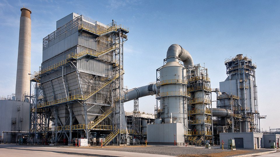
Which emission control train gets specified depends almost entirely on which regulatory standard the project must meet — and those standards vary considerably. China’s GB 13271 / GB 13223 limits are tighter than World Bank Group guidelines in several categories but differ from EU IED Directive thresholds in others. For export EPC projects, this matters because over-specifying scrubbing capacity wastes capital and under-specifying creates permit risk after commissioning.
Electrostatic precipitators handle particulate well on coal combustion where fly ash resistivity stays in a manageable range (roughly 10⁸–10¹¹ Ω·cm). Outside that band — high-sulfur coals pushing resistivity down, or very low-sulfur coals pushing it up — fabric filter baghouses are more reliable, though they carry higher pressure drop and bag replacement costs. Wet FGD using limestone slurry removes SO₂ efficiently (typically 95–99% removal), but produces gypsum byproduct that needs a utilization pathway or lined disposal. Dry and semi-dry systems produce lower-quality reaction product but avoid the wastewater circuit, which simplifies integration in water-scarce locations.
SCR for NOx sits upstream of the air preheater on high-dust configurations — which is standard on most coal units — because catalyst activity is best at flue gas temperatures of 300–420°C. The ammonia or urea injection grid has to be engineered with the boiler load range in mind; at low load, flue gas temperature can drop below SCR activation range, causing NOx exceedances during startup or turndown.
Ash Handling: Often an Afterthought, Rarely a Trivial One
On CFB boilers, bed ash removal is a continuous process, not a batch operation. The fluidized bed accumulates bottom ash constantly, and if removal can’t keep pace with generation, bed inventory builds, differential pressure rises, and the operator starts choking combustion air to compensate — which degrades efficiency and can trip the unit. Properly sized bottom ash coolers (water-cooled or air-cooled) discharging into pneumatic conveying lines to sealed storage silos are not optional on a CFB; they’re part of the combustion control loop in a practical sense.
Fly ash from the ESP or baghouse usually goes by dry pneumatic conveying to pressurized storage silos. This is cleaner and more marketable than hydraulic sluicing — wet ash is harder to sell to cement plants or use as structural fill, and the wastewater circuit adds operating cost. In markets where fly ash command a price as a cement additive (Class F ash from bituminous coal is particularly sought after), dry handling protects that revenue stream.
Cooling Water System: Seasonal Derating Is Real
Condenser performance degrades as cooling water inlet temperature rises. A mechanical-draft cooling tower that delivers 28°C cold-water temperature in spring might be delivering 35°C in August, which raises condenser back-pressure from, say, 5 kPa to 9 kPa — and that alone costs 1.5–2.5% of turbine output. For a 150 MW unit, that’s 2–4 MW of lost generation on peak demand days.
Natural-draft hyperbolic towers have lower auxiliary power draw but higher capital cost and require significant structural civil work; mechanical-draft towers are cheaper to install but consume fan power continuously and require more maintenance attention on drift eliminators and fill media. For industrial power plants in the 25–100 MW range, mechanical-draft is usually the practical choice unless water availability is very constrained and evaporative losses need to be minimized carefully.
Cooling water chemistry — scale inhibitors dosed against calcium carbonate or calcium sulfate precipitation, biocide programs against Legionella and algae fouling — needs to be matched to local makeup water quality. Ignoring conductivity cycles-of-concentration limits degrades condenser tube surfaces over one to two seasons, often invisibly until a tube inspection reveals pitting or deposit buildup.
Electrical Integration and Black-Start Capability
The turbine-generator output feeds the grid through a main step-up transformer. Boiler and turbine auxiliaries — fans, pumps, mills, conveyors — draw from a unit auxiliary transformer tapped off the generator terminals or the high-voltage bus, depending on plant configuration. Sizing the unit auxiliary transformer correctly requires summing all motor nameplate loads with realistic demand factors, not just rated nameplate totals; a common mistake is ignoring inrush current peaks during sequential motor starting after a trip.
Motor control centers with VFDs on large fans and boiler feed pump drives can reduce auxiliary power consumption from a typical 6–9% of gross output down to 4–6%, depending on how aggressively the plant cycles. That delta is meaningful in markets where auxiliary power draws down net revenue.
Black-start capability — the ability to restart the plant from a dead bus using a diesel black-start generator to power the first critical auxiliaries — is often required for industrial plants operating in islanded or weak-grid environments. The sequence matters: the DCS has to come up, then the boiler feedwater pumps, then ignition systems, in a specific order. Getting that startup logic pre-engineered and tested before shipment avoids expensive site commissioning time.
DCS as the Integration Nerve Center
Coordinated boiler-turbine control links turbine load demand to boiler firing rate through a coordinated control system (CCS), sometimes called unit master control. Under CCS, a load demand signal adjusts fuel feed, air flow, and feedwater flow simultaneously rather than sequentially — which dramatically reduces steam pressure swings during load changes and protects superheater metal temperatures.
Turbine trip–boiler runback interlocks are non-negotiable. When the turbine trips, steam flow drops to zero essentially instantly; if the boiler doesn’t shed firing rate within seconds, steam pressure rises toward the safety valve setpoint. A properly engineered runback cuts fuel feed to a pre-purge hold level in under 30 seconds. Without it, every turbine trip becomes a boiler safety event.
Taishan Group supplies complete auxiliary packages including draft fans, ESP/FGD/SCR systems, ash handling, cooling towers, electrical systems, and DCS logic as part of EPC project scope for industrial and utility power plants.True
This reflects the documented EPC and auxiliary supply scope that integrated boiler manufacturers with full project delivery capability provide, and is consistent with Taishan Group's stated business lines covering boilers, auxiliary equipment, and EPC systems for overseas projects.
For EPC clients, having the DCS logic packages pre-engineered by the boiler supplier — with boiler protection curves, fan control loops, and sootblowing sequences already configured — compresses site commissioning from several months to something more manageable. It also means the interlock logic was written by engineers who know the boiler’s actual response characteristics, not adapted from a generic template by a controls contractor who’s never seen that furnace geometry before.
Startup, Shutdown, and Load-Following Procedures for the Integrated Boiler-Turbine-Condenser Unit
Getting the integrated system on-line safely is where most premature failures originate. Not during steady operation — during the transitions.
Cold, Warm, and Hot Start Classifications
The distinction between a cold, warm, and hot start is defined by turbine rotor metal temperature, not by how long the unit has been idle, though the two are correlated. Cold starts begin with rotor temperature below roughly 150°C, warm starts with the rotor between 150–350°C, and hot starts above 350°C. Why does this matter from the boiler side? Because each classification dictates a completely different firing ramp rate and, critically, a different minimum steam admission temperature at the turbine stop valves.
On a cold start of a subcritical drum boiler, initial firing rates are deliberately slow — think 2–4% of rated heat input per hour during early pressure raise — specifically to allow drum metal to heat evenly and limit the temperature differential across thick-walled headers and the turbine casing simultaneously. Push that ramp too fast and you induce differential thermal expansion in the HP turbine rotor that accumulates as fatigue damage. You won’t see it fail today; you’ll see it fail in year four when the rotor inspection finds cracks that nobody can explain. Hot starts allow faster ramps because the metal is already near operating temperature, though “faster” still means controlled — typically the turbine manufacturer specifies steam admission temperature must exceed rotor temperature by no more than 50–80°C to avoid thermal shock.
Light-Off, Steam Raising, and the Bypass System
During boiler light-off on a drum unit, the operator’s first obligation is establishing stable minimum circulation flow through the waterwall circuits before burner firing begins in earnest. Superheater and reheater tubes are the vulnerable items during no-load steam raising because there’s no turbine accepting steam — flow through those tube banks is minimal, and without adequate cooling, metal temperatures climb toward design limits faster than many operators expect, particularly in pendant superheater sections exposed to peak furnace radiation.
This is precisely what the turbine bypass system exists to solve. HP bypass valves route main steam around the HP turbine to the cold reheat line, and LP bypass valves route reheated steam to the condenser through desuperheating stations. During light-off and early pressure raise, the entire steam output goes through this path. The condenser and its cooling water system must be fully operational before bypass steam is admitted — a detail that gets missed in poorly sequenced commissioning schedules more often than it should.
Turbine Rolling and Synchronization: The Boiler Operator’s Window
When the turbine begins rolling toward synchronous speed, boiler operators enter the most demanding control period of the start sequence. Critical speed bands — typically somewhere in the 600–1,800 rpm range depending on rotor design — must be traversed quickly, which means the turbine control system demands a brief steam flow increase that the boiler must accommodate without pressure dip or temperature excursion. Steam temperature stability at the turbine inlet during this window is non-negotiable; a drop of more than roughly 15–20°C can cause the turbine to trip automatically, forcing a restart from scratch.
Synchronization itself — the moment the generator breaker closes onto the grid — requires boiler parameters to be essentially locked. Any pressure oscillation at that instant transmits directly as a load transient.
Load Ramping After Synchronization
Once synchronized, load pickup on a subcritical drum boiler is typically limited to 2–5% of rated load per minute, depending on drum thickness and manufacturer specification. Once-through supercritical units can generally ramp faster — sometimes 5–8% per minute — because there’s no drum with its inherent thermal mass and level control complications.
Drum level management during load steps deserves specific attention. As load increases rapidly, drum pressure momentarily drops, causing bulk water in the drum to flash slightly and the apparent drum level to swell — the “shrink-swell” phenomenon. An inexperienced operator who responds to the apparent high level by reducing feedwater flow will create a genuine low-level condition seconds later. Well-tuned three-element feedwater control (flow, level, and steam flow feedforward) handles this, but control tuning is frequently left in an acceptable-but-not-optimized state after commissioning.
Normal Shutdown and Standby Protection
Normal shutdown follows the reverse sequence: load reduction, turbine unloading, breaker trip, steam dump or bypass operation during turbine rundown, and boiler firing rate reduction to minimum before burner shutdown. Post-purge — continuing forced draft fan operation for a defined period after fuel cutoff — is mandatory to clear unburned combustibles from the furnace and flue gas path.
After shutdown, the items that cause the most corrosion damage during standby are oxygen ingress into the boiler pressure parts and condensate system. Stack dampers and air damper closures should be confirmed shut as soon as flue gas temperature allows. Boiler lay-up practice — whether wet lay-up with deaerated, chemically dosed water or dry lay-up with nitrogen blanketing — depends on the expected standby duration. Units that will restart within a few days typically use wet lay-up; anything beyond two to three weeks generally warrants dry lay-up to prevent oxygen pitting on waterwall and economizer internal surfaces.
Emergency Shutdown and Turbine Trip Response
A turbine trip under load is one of the higher-stress events the boiler experiences in its service life. Steam flow to the turbine drops to zero in under a second. Without fast boiler runback — automatic fuel cutoff and airflow reduction triggered by the DCS interlocks — boiler pressure rises sharply toward safety valve lift pressure. Safety valves lifting is not catastrophic, but it is a maintenance event and a symptom of a DCS runback that was too slow or improperly tuned.
Rapid depressurization after an emergency shutdown can cause water hammer in condensate return lines if the condensate pump continues operating into a collapsed steam space.True
When steam pressure drops suddenly, any remaining steam pockets in low-slope condensate piping condense abruptly, allowing liquid slugs to accelerate and collide — a classic water hammer mechanism. Proper protective interlock logic trips the condensate extraction pumps in sequence with turbine trip to prevent this.
Steam dump to the condenser — via the LP bypass or dedicated dump valves — is the designed path for dissipating steam energy during a trip, but condenser cooling capacity must be adequate to absorb the thermal load. This is a parameter that gets underspecified on smaller industrial power projects where the condenser was sized purely for normal exhaust flow with little margin for dump duty.
A well-designed DCS with properly commissioned protective interlocks converts what could be a cascade failure into a controlled, recoverable event. The quality of that interlock logic — and whether it was actually tested at commissioning with simulated trip scenarios — is one of the most operationally important things an EPC team can verify before handing a plant over to operations.
Performance Monitoring, Efficiency Testing, and Heat Rate Optimization Across the Integrated Plant
Plant heat rate — expressed in kJ/kWh or BTU/kWh — is the single number that tells you how efficiently the entire boiler-turbine-condenser system converts fuel energy into electricity at the generator terminals. Everything else is a component metric. Heat rate is the integrated result. For a subcritical coal-fired unit, expect gross heat rates in the range of 9,500–11,000 kJ/kWh depending on steam parameters, condenser vacuum, and the age of the equipment; supercritical and ultra-supercritical units push that down toward 8,200–9,200 kJ/kWh. The gap between your design curve and your actual monthly average is where money goes.
Decomposing Heat Rate Into Its Root Causes
Boiler-side losses account for a larger share than most operators assume until they actually run the numbers. Dry flue gas loss alone — driven by excess air and stack temperature — typically contributes 4–8% of heat input on a poorly tuned unit. Unburned carbon in fly ash and bottom ash adds another 1–4% on CFB and pulverized coal (PC) units depending on fuel fineness, ash recirculation rate, and combustion residence time. Radiation and convection losses from the boiler casing are smaller, usually 0.3–0.8%, but they are essentially fixed once the unit is built. Moisture in the fuel is a real killer on biomass or high-moisture lignite — each 10 percentage points of surface moisture roughly adds 1.5–2.5% to flue gas heat loss.
Turbine cycle losses are a different category entirely. Condenser back-pressure degradation is usually the largest recoverable loss on an operating plant; at 1 kPa above design absolute pressure, turbine heat rate worsens by roughly 0.3–0.5%, so a condenser running 4 kPa above design on a hot summer day is not a minor nuisance. Feedwater heater terminal temperature differences creeping up — from fouled tubes or partial extraction steam bypass — quietly erode cycle efficiency. Turbine isentropic efficiency degradation from blade erosion or seal wear accumulates over years, and it is nearly invisible unless you’re trending first-stage pressure ratios and comparing them to baseline.
Auxiliary power consumption is the third layer. Forced-draft and induced-draft fans can collectively consume 1.5–3% of plant gross output; on older plants without variable-frequency drives, they often run throttled, wasting 15–30% of the power they draw.
Testing Standards and What They Actually Measure
Boiler efficiency testing under ASME PTC 4 gives you two paths: the input-output method (measure fuel in, heat absorbed out) and the heat loss method (sum all individual losses). In practice, the heat loss method is more accurate at large-scale because fuel flow measurement uncertainty is high. The critical field measurements are stack O₂ (or CO₂), stack temperature corrected for air infiltration, a proximate and ultimate fuel analysis done the same day as the test, and a fly ash and bottom ash sample for unburned carbon. Don’t rely on the plant’s standing fuel analysis — coal quality shifts, sometimes dramatically, between shipments.
Turbine heat rate testing per ASME PTC 6 requires careful mass and energy balance at the turbine boundaries, with correction curves applied for throttle conditions, condenser pressure, and extraction flows. Condenser performance is evaluated against HEI (Heat Exchange Institute) standards, comparing measured cleanliness factor — typically 70–90% on an operating unit — against the design assumption, usually 85%. A condenser running at 72% cleanliness when it was designed for 85% is a maintenance problem with a calculable dollar value attached.
Practical Optimization Without Capital Expenditure
Five levers consistently deliver the best return before you spend anything on hardware:
| Lever | Typical Saving | Key Dependency |
|---|---|---|
| Excess air reduction to 15–20% (PC) or 20–25% (CFB) | 0.3–0.8% fuel reduction | Requires reliable O₂ trim control; risk of CO spike if reduced too fast |
| Stack temperature reduction (each 10°C down) | ~0.5–0.6% fuel saving | Limited by acid dew point on high-sulfur fuels — don’t go below ~130–145°C on most coals |
| Condenser tube cleaning (on-load or offline) | 0.3–1.5% heat rate recovery | Depends on cooling water fouling rate; coastal or river water is the worst |
| Turbine gland seal steam flow minimization | 0.1–0.3% | Requires leak-off measurement; often neglected |
| FD/ID fan VFD installation or setpoint retraining | 0.5–1.8% auxiliary saving | High upfront cost if retrofitting, but VFD payback is typically 2–4 years |
Continuous Monitoring and Soot Blowing
Online heat rate calculation in the DCS — using real-time fuel flow, generator output, and correction factors for steam parameters and ambient conditions — lets operators see the current efficiency deviation against design within minutes, not months. The key is that the corrected design curve must be accurate; plants that load a generic curve from the original proposal rather than the as-tested acceptance curve end up chasing phantom deviations.
Soot blowing deserves specific attention because the wrong strategy hurts you in two directions simultaneously. Over-blowing erodes convective pass tubes and superheater pendants, and wastes 0.5–1.5% of main steam flow as blowing steam. Under-blowing lets ash bridging build on the economizer and air heater, pushing stack temperature up by 15–30°C over a few weeks — that’s 1–2% efficiency loss you can watch develop in real time if you’re trending stack temperature against a clean baseline.
Intelligent soot blowing systems using acoustic or infrared sensors to target blowing only to fouled tube banks can reduce blowing steam consumption by 20–40% compared to time-based sequential blowing.True
Acoustic pyrometry and IR sensing systems assess actual cleanliness of individual tube bank sections, enabling selective activation; published utility case data and system supplier performance data consistently report steam savings in the 20–40% range, with secondary benefits in reduced tube erosion.
In practice, most industrial and small utility plants don’t invest in acoustic soot blowing until they’ve already had a superheater erosion failure or a persistent stack temperature problem they can’t solve any other way. That’s a reactive approach. If your unit runs on high-ash coal — anything above 25–30% ash content — intelligent blowing optimization pays back faster than you might expect, usually within two to three operating years.
Frequently Asked Questions About Power Plant Boiler Integration With Turbines and Condensers
What steam pressure and temperature should I specify for my power boiler to match a specific turbine generator size?
The short answer: coordinate with both suppliers before FEED is locked. Steam parameters follow fairly well-established tiers in practice. For industrial power applications in the 25–150 MW range, subcritical designs at roughly 9.8–13.7 MPa and 535–540°C main steam temperature are standard — the turbine OEM catalogs align to these parameters, and the boiler fabrication is within reach of most certified manufacturers without exotic alloys. Step up to 100–300 MW and you’re looking at high-subcritical designs, typically 13.7–16.7 MPa, still around 540°C but with tighter tolerances on steam chemistry and pipe wall thickness. Above 300 MW, supercritical parameters (24 MPa and above, with main and reheat steam temperatures often 566–600°C) come into play, and at that point, material selection — P91, P92 creep-resistant steels — drives both cost and lead time significantly.
What goes wrong: plants that specify the boiler independently of the turbine sometimes end up with a steam line designed for one flow velocity while the turbine control valves are sized for another. The resulting pressure drop across the main steam line, especially on longer pipe runs, can cost you 1–3% output at full load. Specify the interface conditions at the turbine stop valve, not at the boiler outlet flange.
Can an existing industrial boiler be integrated with a new turbine-generator to generate electricity from waste steam?
Yes, but the boiler needs a careful pressure-part inspection first. A boiler that’s been running for 10–15 years at, say, 1.6 MPa for process heat is not simply “connected” to a back-pressure turbine. Minimum practical steam conditions for a back-pressure turbine to generate useful power are roughly 1.0–1.6 MPa inlet with at least 5–8 t/h of sustained flow — below that, the economics rarely work out. Extraction-condensing turbines give more flexibility if the downstream process heat demand is variable.
The inspection matters because furnace tube wall thickness, header welds, and safety valve certification may all need upgrading once the boiler is reclassified as part of a power generation system. Skipping this step has caused unplanned outages within the first year of operation on more than a few retrofit projects.
How does an HRSG differ from a conventional fired boiler in terms of turbine integration?
An HRSG has no burner managing combustion to control steam output — the heat source is gas turbine exhaust, typically 450–600°C depending on the GT model and load. Steam output rises and falls with gas turbine load, not with a fuel valve. Most utility-grade HRSGs use a multi-pressure arrangement (HP, IP, LP drums) to extract as much energy as possible from the exhaust gas profile. A duct burner can supplement firing when additional steam is needed, but it’s supplemental, not primary.
The integration consequence: when the gas turbine trips, steam production collapses in seconds rather than minutes. Steam turbine load shedding controls must be faster and more tightly coordinated than in a conventional fired-boiler plant. This is a point that sometimes gets underspecified during CCGT project scoping.
What causes condenser fouling, and how often should condenser tubes be cleaned in a tropical climate?
Warm cooling water accelerates biofouling sharply — above roughly 30°C, biological growth rates in open cooling systems can double compared to temperate climates. Slime-forming bacteria and algae colonize tube surfaces within weeks if treatment is inconsistent, and even a thin fouling layer (0.1–0.2 mm) measurably degrades heat transfer, pushing condenser pressure up and eating into turbine output.
For continuous operation, online sponge ball cleaning systems are worth the capital cost. They keep tubes mechanically clean without shutdown, which matters in climates where seasonal cooling water temperatures stay elevated for months. During a planned annual outage, mechanical tube cleaning and eddy-current inspection together typically take 4–8 days for a medium-sized condenser.
Tube material selection affects how quickly fouling establishes itself. Titanium tubes have the lowest long-term fouling propensity but carry a significant cost premium. Admiralty brass is common in coastal plants using seawater cooling, with cathodic protection added. Stainless steel (304, 316) sits in between on both cost and fouling resistance.
What is the minimum boiler load at which stable integration with the turbine-condenser system is possible?
This depends heavily on boiler type. CFB boilers are generally more flexible than pulverized coal — minimum stable load (MSL) for a CFB is typically 25–35% of MCR, constrained partly by minimum fluidizing velocity in the bed. Drop below that and you risk bed defluidization, which is expensive to recover from. PC boilers tend to have an MSL of 30–40% MCR, limited by combustion stability at low coal feed rates and burner turndown ratio. Gas-fired HRSGs are the most flexible, often operating stably down to 15–25% MCR because the GT exhaust is always present and combustion isn’t the variable being managed.
The turbine side imposes its own floor — most steam turbines require a minimum steam flow to maintain blade cooling and bearing stability, typically around 20–30% of rated flow. In practice, the combined system MSL is whichever constraint is more restrictive: often the boiler.
How long does it take to commission and integrate a new power boiler with an existing turbine-generator?
Roughly 60–120 days from first fire to commercial operation, but that range depends heavily on whether auxiliaries are pre-commissioned in parallel and whether steam blowing complications arise. A realistic phase breakdown:
| Phase | Typical Duration |
|---|---|
| Hydraulic pressure test | 3–7 days |
| Steam blowing (turbine protection) | 7–21 days (longer at higher pressures) |
| Cold/hot functional testing of auxiliaries | 14–30 days |
| Trial operation (72-hour reliability run) | 3–5 days |
| Performance acceptance test | 3–7 days |
Steam blowing is the phase that most often surprises clients on timeline. At supercritical parameters, achieving the required cleanliness factor (typically ≥1.0 per ASME or equivalent) can require many blow cycles over two to three weeks.
What certifications and quality standards should I require from a power boiler manufacturer for an overseas EPC project?
At minimum: ASME Section I for pressure parts if the project is in North America or if the client requires ASME stamping for insurance or financing reasons. CE marking under the Pressure Equipment Directive (PED 2014/68/EU) for European installations. ISO 9001 quality management and ISO 14001 environmental management are baseline expectations for any serious EPC procurement — they’re not guarantees of quality, but their absence is a red flag.
Country-specific type approval matters more than people realize. Some Southeast Asian and African markets require local authority sign-off on the boiler design before erection permits are issued, and getting that retroactively is painful.
Taishan Group boilers are manufactured under certified quality management systems and have been supplied to overseas EPC projects with third-party inspection by bodies including Bureau Veritas, Lloyd's Register, and TÜV.True
Third-party inspection by recognized certification bodies is standard practice for export-grade power boilers and verifiable through project documentation and inspection certificates.
Third-party inspection — Bureau Veritas, Lloyd’s Register, TÜV — during fabrication, not just at final delivery, is worth specifying explicitly in the purchase contract. Waiting until the boiler arrives on site to discover a weld nonconformance costs far more than the inspection fees.