Environmental and Emission Regulations Impacting Industrial Steam Boiler Selection
Environmental and Emission Regulations Impacting Industrial Steam Boiler Selection
In an era of tightening environmental policies and growing climate accountability, environmental and emission regulations are now among the most critical factors influencing the selection of industrial steam boilers. These regulations not only govern the types and levels of pollutants a boiler can emit but also impact decisions about fuel type, burner design, flue gas treatment, monitoring equipment, and long-term operational strategies. Failing to comply with local or international emission standards can result in fines, permit delays, legal penalties, and costly retrofits.
Environmental and emission regulations impact industrial steam boiler selection by setting strict limits on pollutants such as nitrogen oxides (NOx), sulfur oxides (SOx), carbon monoxide (CO), carbon dioxide (CO₂), particulate matter (PM), and volatile organic compounds (VOCs). These requirements influence decisions on fuel sources, combustion technologies, emission control systems (like SCR, ESP, FGD), boiler sizing, and the necessity of continuous emissions monitoring (CEMS). Regulatory bodies such as the U.S. EPA, EU IED, and national environmental agencies enforce these standards through permits and compliance reporting.
Understanding and designing for regulatory compliance from the start ensures that your boiler investment remains viable, legal, and sustainable.
What Are the Key Regulated Emissions for Industrial Steam Boilers?
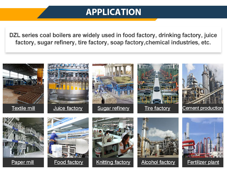
Industrial steam boilers are critical to sectors like power generation, textiles, paper, chemicals, and food processing. However, these boilers are also significant sources of air pollutants, especially when burning coal, oil, biomass, or waste fuels. To minimize environmental and public health risks, most countries enforce strict emission limits on specific pollutants released from the boiler stack. Understanding which emissions are regulated—and why—is essential for designing compliant systems, selecting the right fuel and technology, and implementing effective emission control strategies.
The key regulated emissions for industrial steam boilers include nitrogen oxides (NOₓ), sulfur oxides (SOₓ), particulate matter (PM), carbon monoxide (CO), carbon dioxide (CO₂), volatile organic compounds (VOCs), and heavy metals such as mercury (Hg). These pollutants are regulated due to their roles in smog formation, acid rain, climate change, respiratory illness, and environmental toxicity. Emission limits vary by country, fuel type, boiler capacity, and regulatory framework, but all require continuous or periodic monitoring and control.
Compliance with emission regulations is a legal obligation and a foundation of sustainable boiler operation.
Industrial steam boilers are regulated for emissions such as NOx, SOx, PM, CO, CO2, and mercury.True
These pollutants have serious health and environmental impacts and are subject to strict national and international emission standards.
🔍 Overview of Key Regulated Boiler Emissions
| Pollutant | Full Name | Primary Concern | Major Sources |
|---|---|---|---|
| NOₓ | Nitrogen Oxides | Ground-level ozone (smog), lung irritation | High-temp combustion |
| SOₓ | Sulfur Oxides | Acid rain, metal corrosion | Sulfur in fuel (coal, oil, biomass) |
| PM | Particulate Matter | Respiratory disease, haze, equipment fouling | Ash, soot, unburned fuel |
| CO | Carbon Monoxide | Toxic gas, incomplete combustion | Poor combustion control |
| CO₂ | Carbon Dioxide | Greenhouse gas, climate change | Combustion of all carbon-based fuels |
| VOCs | Volatile Organic Compounds | Smog formation, toxic exposure | Organic compounds in some fuels |
| Hg | Mercury | Neurotoxin, bioaccumulation in ecosystems | Trace in coal and biomass |
Each pollutant is regulated for a specific health or environmental reason.
📏 Typical Emission Limits by Region (mg/Nm³)
| Pollutant | EU IED | US EPA MACT | India CPCB | China GB13271 |
|---|---|---|---|---|
| NOₓ | 150–200 | 180–250 | 300–450 | 200–300 |
| SOₓ | 150–200 | 250 | 100–600 | 200–400 |
| PM | 10–20 | 25–30 | 30–50 | 20–30 |
| CO | 100–150 | 150 | 100–200 | 100–150 |
| Hg | 0.03–0.05 | 0.001–0.002 | Not specified | 0.03–0.05 |
| CO₂ | Regulated by carbon market or tax | Climate programs | PAT scheme (intensity-based) | Carbon ETS (pilot) |
→ Standards vary based on fuel (e.g., coal, gas, biomass), boiler size, and load.
🛠 Pollutant-Specific Emission Control Technologies
| Pollutant | Common Control Methods | Efficiency (%) |
|---|---|---|
| NOₓ | Low-NOx burners, SNCR, SCR | 50–95% |
| SOₓ | FGD (wet/dry), limestone injection | 80–98% |
| PM | ESP, baghouse, multicyclone | 95–99.9% |
| CO | Burner tuning, air-fuel ratio control | Up to 90% |
| CO₂ | Efficiency improvement, CCS (emerging) | 5–90% (CCS) |
| Hg | Activated carbon injection (ACI), baghouse | 80–95% |
→ Most compliant boilers use multi-layered systems to address all regulated emissions simultaneously.
📊 Example: Emission Profile of a 10 TPH Biomass Boiler (Wood Chips)
| Pollutant | Uncontrolled (mg/Nm³) | Controlled (mg/Nm³) | Compliance with CPCB Norms? |
|---|---|---|---|
| NOₓ | 420 | 250 | ✅ Yes |
| SOₓ | 280 | 180 | ✅ Yes |
| PM | 120 | 28 | ✅ Yes |
| CO | 300 | 130 | ✅ Yes |
→ Achieved using SNCR, bag filter, and O₂ trim system.
🔍 Monitoring Requirements for Regulated Emissions
| Pollutant | Monitoring Frequency | Monitoring Tool |
|---|---|---|
| NOₓ, SOₓ, CO | Continuous (CEMS required) | Infrared or chemiluminescence analyzers |
| PM | Continuous or periodic | Opacity monitor, gravimetric sampler |
| CO₂ | Continuous or calculated | Flow-based GHG calculators, CEMS extension |
| Hg | Continuous (in US/EU), periodic elsewhere | Sorbent traps, mercury CEMS |
| VOCs | Periodic | GC-FID analyzers, flame ionization detector |
→ CEMS (Continuous Emissions Monitoring Systems) are mandatory in most jurisdictions for large boilers.
🧪 Real-World Case Study – Industrial Steam Boiler Compliance in China
Boiler: 20 TPH coal-fired
Issue: PM and SO₂ exceedances during audit
Solutions:
Installed baghouse for PM <30 mg/Nm³
Upgraded to wet FGD system
Burner tuning to reduce NOₓ below 250 mg/Nm³
Result:
Full compliance with GB13271-2014
Permit retained, eligible for tax incentives
CO₂ emission intensity reduced by 7.2%
🛠 Engineering Considerations for Emission Compliance
| Design Decision | Emission Impact |
|---|---|
| Fuel Type (coal vs. biomass) | High-S or high-ash fuels = more SOx/PM |
| Combustion System | Low-NOx burner reduces NOx formation |
| Heat Recovery & Efficiency | Lower CO₂ emissions per unit of output |
| Post-Combustion Controls | Essential to meet tight PM and Hg limits |
Choosing a compliant boiler is as much about emission management as it is about steam output.
In conclusion, industrial steam boilers must control and monitor a specific set of emissions—including NOₓ, SOₓ, PM, CO, CO₂, VOCs, and Hg—to comply with environmental regulations and protect public health. These emissions are tightly regulated due to their toxic, corrosive, or climate-changing properties. For plant operators and engineers, emission management is no longer optional—it is integral to design, operation, and long-term viability of industrial steam systems.
Which Global and Regional Environmental Regulations Apply to Steam Boiler Systems?
As industrial steam boilers continue to serve critical roles across sectors like manufacturing, power, and process industries, they are also major sources of air pollutants. Governments around the world enforce strict environmental regulations to control emissions from these systems. These rules differ by region, but they all aim to limit pollutants such as NOₓ, SOₓ, PM, CO, CO₂, and toxic metals through technology mandates, emission thresholds, and continuous monitoring requirements. Whether you’re operating a coal-fired, gas-fired, oil-fired, or biomass boiler, understanding and adhering to these frameworks is essential for permit approval, legal operation, and long-term environmental compliance.
Steam boiler systems are subject to various global and regional environmental regulations, including the European Union’s Industrial Emissions Directive (EU IED), the U.S. EPA’s National Emission Standards for Hazardous Air Pollutants (NESHAP/MACT), China’s GB13271 emission standard, and India’s CPCB 2017 boiler norms. These regulations mandate limits on pollutants such as NOₓ, SOₓ, PM, and CO₂, require emissions monitoring, and often specify allowable fuels and combustion technologies. Compliance is necessary for operating permits, environmental certifications, and avoidance of penalties.
Global boiler regulation is no longer just about emissions—it’s about climate alignment, fuel selection, and technology readiness.
Steam boiler systems are regulated under international and national emission standards depending on region and fuel type.True
Laws like the EU IED, US EPA MACT, and India's CPCB norms mandate emission limits, control technologies, and monitoring requirements for steam boilers.
🌍 Key Global and Regional Environmental Regulations for Steam Boilers
| Regulation/Agency | Region | Key Focus |
|---|---|---|
| EU IED (2010/75/EU) | European Union | Integrated emission limits for SOₓ, NOₓ, PM, and CO₂; BAT-based approach |
| BREF for LCP | EU | Best Available Techniques for Large Combustion Plants (>50 MWth) |
| US EPA MACT (Boiler Rule) | United States | Hazardous air pollutants (HAPs), NOₓ, SO₂, PM; applies to major and area sources |
| China GB13271-2014 | China | Emission limits for pollutants from stationary sources, tailored by fuel and size |
| India CPCB 2015 & 2017 | India | PM, NOₓ, SOₓ limits by capacity, age, and location of boilers |
| South Africa AQA | South Africa | Air Quality Act governs industrial emissions including boilers |
| ISO 14001 / GHG Protocol | Global (voluntary) | Environmental and climate disclosure frameworks including boiler GHG emissions |
📏 Emission Limits in Major Jurisdictions (mg/Nm³ unless noted)
| Region | PM (mg/Nm³) | NOₓ (mg/Nm³) | SO₂ (mg/Nm³) | CO (mg/Nm³) | Hg (µg/Nm³) | CEMS Required |
|---|---|---|---|---|---|---|
| EU (IED) | ≤10–30 | ≤150–200 | ≤150 | ≤100 | ≤30 | Yes |
| USA (EPA MACT) | ≤20–30 | ≤180–250 | ≤250 | ≤150 | ≤5 | Yes |
| China (GB13271) | ≤20–30 | ≤300 | ≤200–400 | ≤100–150 | ≤30 | Yes (≥10 TPH) |
| India (CPCB 2017) | ≤30–50 | ≤300–450 | ≤100–600 | ≤150–200 | Not Specified | Yes (≥10 TPH) |
→ Regulations differ by fuel type (coal, gas, biomass) and boiler capacity (e.g., <10 TPH vs. >50 MWth).
🛠 Technologies Mandated or Encouraged by Regulation
| Regulation | Technology Encouragements or Mandates |
|---|---|
| EU IED / BREF | Low-NOx burners, SCR/SNCR, ESP or baghouse, FGD, energy recovery |
| EPA MACT (USA) | PM control (ESP/baghouse), Hg capture (ACI), combustion tuning |
| China GB13271 | CEMS, SNCR, ash handling, desulfurization systems |
| India CPCB 2017 | SNCR/SCR, bag filter/ESP, O₂ monitoring, wet scrubber |
Non-compliant plants risk penalties, shutdowns, or revocation of environmental clearance.
📊 Real-World Example – Regulation-Driven Upgrade (India)
| Project Component | Before Regulation (2015) | After CPCB 2017 Compliance |
|---|---|---|
| Boiler Size | 35 TPH Coal-Fired | Same |
| PM Emissions | 95 mg/Nm³ | 28 mg/Nm³ (Baghouse installed) |
| NOₓ Control | None | SNCR with urea dosing system |
| SO₂ Control | Lime injection added | Emissions <450 mg/Nm³ |
| Monitoring | Manual logbook | CEMS integrated with CPCB |
| Result | Legal compliance, GHG reduction credits unlocked |
→ Ensured permit renewal and alignment with ESG targets.
📈 Penalties and Incentives in Global Boiler Regulation
| Region | Non-Compliance Penalties | Compliance Incentives |
|---|---|---|
| EU | Fines, shutdown, denial of permit renewals | Carbon trading eligibility, green financing |
| USA | EPA fines ($25,000+/day), injunctive relief | ENERGY STAR and tax credits |
| China | Public violation notices, production halts | Preferential electricity pricing |
| India | CPCB closure notices, fines, legal action | PAT scheme energy savings certificates |
| South Africa | Emission tax, criminal charges | Carbon offset mechanisms |
→ Environmental compliance is not just about avoiding penalties—it opens doors to incentives.
🌐 Alignment with Global Climate and ESG Frameworks
| Global Framework | Relevance to Boiler Emissions |
|---|---|
| UNFCCC / Paris Agreement | Targets CO₂ and GHG reduction |
| ISO 14001 | Environmental management system certification |
| SBTi (Science-Based Targets) | Requires scope 1 emissions reduction (including boilers) |
| GHG Protocol (Scope 1) | Boiler CO₂ and CH₄ emissions are reportable |
| CDP Climate Disclosure | Companies must report industrial combustion emissions |
Boiler systems must now fit into corporate decarbonization plans and ESG disclosures.
🧪 Compliance Roadmap for Boiler Projects
| Step | Action |
|---|---|
| Step 1 | Identify applicable national regulations |
| Step 2 | Assess boiler fuel type, size, and age |
| Step 3 | Conduct emission audit or baseline study |
| Step 4 | Retrofit or design appropriate control systems |
| Step 5 | Install CEMS and set up reporting to regulators |
| Step 6 | Align with ESG/climate reporting obligations |
Early alignment reduces compliance risk and improves long-term operational resilience.
In conclusion, steam boilers are subject to a variety of global and regional environmental regulations that govern their emissions, fuel types, and monitoring systems. Whether you’re operating in Europe, the U.S., Asia, or Africa, staying compliant requires a thorough understanding of applicable laws and integrating emission control technologies accordingly. Beyond avoiding penalties, regulatory compliance offers access to carbon markets, green finance, and reputational value in today’s climate-conscious economy.
How Do Fuel Type and Burner Design Affect Regulatory Compliance?
Fuel type and burner design are not just technical variables—they’re core determinants of regulatory compliance in industrial boiler systems. From particulate matter in coal combustion to nitrogen oxides in gas burners, different fuels inherently produce different emissions. The burner’s ability to mix air and fuel, control flame temperature, and promote complete combustion plays a critical role in limiting these emissions. Regulatory agencies worldwide impose specific pollutant limits that vary based on fuel source and combustion technology, making the right fuel-burner combination essential for legal operation and emissions control.
Fuel type and burner design directly impact regulatory compliance by determining the quantity and type of pollutants emitted during combustion. Fuels such as coal and biomass produce higher PM and SOx, requiring more advanced emission controls, while gas emits lower PM but more NOx under high-temperature flames. Burner design affects how efficiently fuel burns, influencing CO, NOx, and unburned hydrocarbons. A mismatch between fuel characteristics and burner capability can lead to regulatory exceedances, permit violations, and penalties.
In modern boiler systems, compliance starts at the fuel feeder and burner nozzle—not just the stack.
Fuel type and burner design directly impact emission levels and regulatory compliance.True
Different fuels emit different pollutants, and burner design affects how completely and cleanly the fuel burns, which in turn determines whether emission standards are met.
🔍 How Fuel Type Influences Emission Profiles
| Fuel Type | PM | NOx | SOx | CO | Hg | CO₂ |
|---|---|---|---|---|---|---|
| Coal | High | Medium–High | High | Medium | High | High |
| Biomass | Medium–High | Medium | Low–Medium | Medium | Low | Neutral–Medium |
| Natural Gas | Very Low | High (thermal NOx) | Negligible | Low | Negligible | Medium |
| Fuel Oil | Medium | Medium–High | Medium–High | Medium | Medium | High |
| Waste Fuels (RDF) | High | Variable | Variable | High | High | High |
→ Regulatory requirements are stricter for dirtier fuels due to their pollutant load.
🔧 Burner Design Features That Influence Compliance
| Burner Feature | Emission Impact | Relevance to Regulation |
|---|---|---|
| Air-Fuel Mixing | Affects CO, PM, VOCs | Poor mixing = high CO, visible smoke |
| Flame Temperature Control | Affects NOx formation | Lower flame temp = less thermal NOx |
| Atomization (for liquids) | Affects combustion completeness | Fine droplets = less unburned fuel |
| Swirl/Staging Design | Improves combustion stability and burnout | Helps meet low-NOx targets |
| Turn-Down Ratio | Supports stable combustion at low loads | Prevents CO and cycling-related emissions |
→ Burners must be designed or tuned to match fuel combustion characteristics for compliance.
📏 Region-Specific Fuel and Burner Regulations (Examples)
| Region | Fuel-Based Regulation | Burner/Technology Requirement |
|---|---|---|
| EU (IED) | Fuel-specific BAT limits for NOx, SOx, PM | Requires low-NOx burners, staged combustion |
| USA (EPA MACT) | HAP limits for solid/liquid/gas boilers | Burner tuning, O₂ control, PM filters |
| China (GB13271) | Differentiated limits for biomass, coal, gas | Burner and CEMS verification |
| India (CPCB 2017) | Limits by fuel and boiler size | Burner optimization + emission control tech |
Non-compliance can result in denied permits, operational shutdowns, or heavy fines.
📊 Example – Burner-Fuel Pairing and Compliance Risk
| Fuel + Burner Setup | PM (mg/Nm³) | NOx (mg/Nm³) | CO (ppm) | Regulatory Status |
|---|---|---|---|---|
| Coal + basic burner (no staging) | 120 | 420 | 250 | ❌ Exceeds limits |
| Biomass + stoker + bag filter | 28 | 260 | 140 | ✅ Compliant |
| Natural Gas + low-NOx burner | 7 | 120 | 35 | ✅ Compliant |
| HFO + pressure jet burner | 45 | 320 | 180 | ⚠ Requires scrubber |
→ Even clean fuels like gas require correct burner design to control NOx emissions.
🛠 Matching Fuel and Burner for Compliance Success
| Fuel Type | Recommended Burner Type | Required Controls for Compliance |
|---|---|---|
| Coal | Pulverized coal burner or CFB | ESP/baghouse, FGD, low-NOx design |
| Biomass | Moving grate or FBC | Multicyclone or fabric filter, staged air |
| Gas | Low-NOx premix or staged burner | O₂ trim, flue gas recirculation (FGR) |
| Fuel Oil | Air or steam-atomized burner | SCR/SNCR, soot blowers, CO tuning |
| Waste RDF | Rotary kiln or hybrid burner | ACI for Hg, high-temp staging, baghouse |
Correct pairing ensures regulatory compliance and stable boiler operation.
🧪 Real-World Case – Compliance Upgrade via Burner Retrofit
Plant: 15 TPH biomass boiler
Problem: NOx > 400 mg/Nm³, CO > 200 ppm
Root Cause: Inadequate air-fuel mixing in stoker burner
Solution:
Replaced with staged combustion burner
Added O₂ sensor for trim control
Installed bag filter for PM
Result:
NOx reduced to 230 mg/Nm³
CO reduced to 80 ppm
Achieved full CPCB 2017 compliance
Efficiency improved by 4.2%
📈 Burner-Fuel Design Checklist for Emission Compliance
| Design Area | Compliance Function |
|---|---|
| Fuel Analysis (CV, moisture, ash) | Informs burner air-fuel matching |
| Burner Air Staging | Controls NOx and CO |
| Flame Shape Optimization | Ensures full burnout |
| Atomization Type (for oils) | Prevents soot and CO formation |
| Burner Control Integration | Real-time efficiency and emission feedback |
→ Compliance is achieved not by emission controls alone—but by engineering combustion correctly.
In conclusion, fuel type and burner design are foundational to regulatory compliance in steam boiler systems. Each fuel presents unique combustion and emission challenges, and burner performance determines whether those challenges are managed effectively. Choosing the right burner for your fuel—and maintaining optimal air-fuel mixing and flame control—is essential not just for efficiency, but for legal and environmental integrity. In modern boiler operations, compliance starts with combustion.
What Emission Control Technologies Are Required to Meet NOx, SOx, and PM Limits?
Industrial steam boilers, particularly those firing solid and liquid fuels, are significant point sources of air pollutants such as nitrogen oxides (NOx), sulfur oxides (SOx), and particulate matter (PM). These emissions are tightly regulated across the globe due to their harmful effects on human health, air quality, and ecosystems. Achieving compliance with regional and international emission standards requires the deployment of dedicated flue gas cleaning systems—each tailored to control specific pollutants. Selection of appropriate emission control technologies depends on fuel type, combustion method, stack flow rates, and regulatory limits.
To meet emission limits for NOx, SOx, and PM in industrial boiler systems, a combination of Selective Catalytic Reduction (SCR) or Selective Non-Catalytic Reduction (SNCR) for NOx, Flue Gas Desulfurization (FGD) systems for SOx, and Electrostatic Precipitators (ESP) or fabric filters (baghouses) for PM is typically required. These technologies are often used in series to ensure each pollutant is captured before discharge, ensuring compliance with EU, US EPA, India CPCB, and China GB13271 regulations.
Each component plays a vital role in delivering a clean, regulation-compliant exhaust stream.
Emission control technologies like SCR, FGD, and ESP are required to meet NOx, SOx, and PM limits in industrial boilers.True
These technologies are designed to remove specific pollutants and are often required by law to meet regional and international air quality standards.
🔍 Overview of Primary Emission Control Technologies
| Pollutant | Control Technology | Removal Efficiency (%) | Common Application |
|---|---|---|---|
| NOx | SNCR (urea or ammonia injection) | 30–60% | Biomass, coal, oil |
| SCR (catalyst-based) | 80–95% | Natural gas, coal | |
| SOx | Dry FGD (lime injection) | 70–90% | Biomass, RDF |
| Wet FGD (limestone slurry) | 90–98% | Coal, oil | |
| PM | Electrostatic Precipitator (ESP) | 95–99.5% | Coal, biomass |
| Baghouse (Fabric Filter) | 98–99.9% | Biomass, RDF, waste |
→ Systems are often combined into multi-stage pollution control trains.
📊 Example – Flue Gas Cleaning System for a 30 TPH Coal Boiler
| Emission | Raw Stack Level | Control Tech Used | Final Emission | Regulation Met? |
|---|---|---|---|---|
| NOx | 420 mg/Nm³ | SNCR (urea) | 210 mg/Nm³ | ✅ (EU < 200, India < 300) |
| SOx | 520 mg/Nm³ | Wet FGD | 80 mg/Nm³ | ✅ (All regions) |
| PM | 110 mg/Nm³ | ESP | 28 mg/Nm³ | ✅ (India < 30) |
→ Final stack emissions fully compliant with CPCB, EU IED, and China GB13271 norms.
🛠 NOx Control Technologies: SNCR vs. SCR
| Feature | SNCR | SCR |
|---|---|---|
| Process | Urea or ammonia injected into furnace | Same reagent passed through catalyst bed |
| Temp. Range | 850–1100°C | 300–400°C |
| Reduction Efficiency | 30–60% | 80–95% |
| Cost | Lower CAPEX | Higher CAPEX + OPEX |
| Fuel Compatibility | Biomass, coal, oil | Gas, coal, oil |
| Maintenance | Moderate | Catalyst inspection/replacement |
→ SCR preferred in gas-fired and high-efficiency plants.
💨 SOx Control Technologies: FGD Systems
| Technology | Type | Key Features |
|---|---|---|
| Wet FGD | Limestone slurry | Most effective, high SO₂ absorption (>95%) |
| Dry FGD | Hydrated lime injection | Simpler, used for smaller units |
| Semi-dry FGD | Atomized lime spray | Hybrid between wet and dry, 85–90% removal |
| In-furnace Desulfurization | Limestone with fuel | Lower efficiency (~50–60%) |
FGD systems are essential for high-sulfur fuels like coal or petcoke.
🌫 PM Control Technologies: ESP vs. Baghouse
| Feature | ESP | Baghouse |
|---|---|---|
| Collection Method | Electrostatic charge | Mechanical filtration |
| Efficiency | 95–99.5% | 98–99.9% |
| Fuel Type Suitability | Coal, biomass | High-ash, variable-fuel blends |
| Sensitivity to Moisture | Yes | Less affected |
| Maintenance | Lower filter change rate | Requires periodic bag replacement |
→ Baghouses are preferred for biomass and waste with variable ash content.
📏 Global Emission Limits Driving Control Technology Use
| Region | NOx (mg/Nm³) | SOx (mg/Nm³) | PM (mg/Nm³) | CEMS Required | Control Tech Expectation |
|---|---|---|---|---|---|
| EU (IED) | ≤200 | ≤150 | ≤10–30 | Yes | SCR, FGD, baghouse/ESP |
| USA (MACT) | ≤180–250 | ≤250 | ≤20–30 | Yes | SCR or SNCR, FGD, ESP |
| China GB13271 | ≤300 | ≤400 | ≤20–30 | Yes | SNCR, semi-dry FGD, baghouse |
| India CPCB | ≤300–450 | ≤100–600 | ≤30–50 | Yes | SNCR, dry FGD, ESP |
→ Each region imposes strict requirements, influencing boiler and emissions system design.
🧪 Real-World Upgrade: 20 TPH Biomass Boiler (India CPCB 2017 Compliance)
Problem: PM = 90 mg/Nm³, NOx = 430 mg/Nm³
Actions Taken:
Installed baghouse filter → PM < 28 mg/Nm³
Added SNCR with urea dosing → NOx = 220 mg/Nm³
Implemented oxygen trim and CO monitoring
Result:
Full regulatory compliance
Improved boiler efficiency by 5.2%
Reduced CO₂ intensity by 6.7%
📈 Integrated Emission Control Strategy for Modern Boilers
| Control Stage | Target Pollutant | Technology Used |
|---|---|---|
| Combustion Optimization | CO, NOx | Burner tuning, O₂ trim |
| In-furnace Control | NOx, SOx | Staged air, limestone injection |
| Flue Gas Conditioning | SOx, PM | FGD, ammonia injection |
| Final Particulate Capture | PM | ESP or bag filter |
| Continuous Monitoring | All | CEMS and DAHS |
→ A layered approach ensures legal compliance and operational reliability.
In conclusion, emission control technologies such as SCR/SNCR, FGD systems, and ESPs or baghouses are essential to meet NOx, SOx, and PM limits in industrial steam boiler systems. Each technology targets a specific pollutant and must be selected based on fuel characteristics, local regulations, and boiler capacity. In today’s regulatory environment, emission control is not optional—it is a critical design and operational requirement for any responsible and future-ready steam generation system.

Why Is Continuous Emissions Monitoring (CEMS) Essential for Compliance?
Environmental regulations for steam boiler systems are becoming increasingly stringent across the globe. Simply installing pollution control equipment is no longer enough—regulators demand proof that emission limits are being met at all times. This is where Continuous Emissions Monitoring Systems (CEMS) come into play. These systems provide real-time, continuous data on pollutant emissions directly from the stack, ensuring accurate reporting, early warning of deviations, and robust evidence for compliance audits. Without CEMS, plants face a higher risk of violations, penalties, or permit rejections due to incomplete or inaccurate emissions reporting.
Continuous emissions monitoring (CEMS) is essential for regulatory compliance because it provides real-time, verifiable, and continuous data on key pollutants like NOx, SOx, CO, CO₂, and PM. It ensures that emissions remain within permitted limits, supports mandatory reporting to environmental authorities, detects control system failures early, and proves compliance during audits. Many regions—including the EU, USA, China, and India—require CEMS by law for medium to large-capacity boilers.
In modern environmental governance, “If you didn’t measure it, you didn’t comply.”
CEMS is essential for emissions compliance in regulated industrial boiler systems.True
It provides continuous, accurate, and verifiable data on pollutant emissions, which is required by most environmental authorities for legal operation and auditing.
🔍 What Does a CEMS Monitor?
| Pollutant | Why It’s Monitored | Regulatory Threshold Examples (mg/Nm³) |
|---|---|---|
| NOx | Contributes to smog and ozone | EU ≤ 150, India ≤ 300, China ≤ 300 |
| SOx | Causes acid rain | EU ≤ 150, India ≤ 100–600 |
| CO | Indicates incomplete combustion | EU ≤ 100, US ≤ 150 |
| CO₂ | Climate regulation, carbon markets | Varies (GHG intensity limits, carbon tax) |
| PM | Respiratory hazard | EU ≤ 10–30, India ≤ 50 |
| O₂ | Required for combustion control validation | Target range: 3–6% |
| Opacity | Visual emissions indicator | Often required in coal or waste boilers |
→ CEMS ensures pollutants are continuously below limits—not just during annual inspections.
🛠 Components of a Typical CEMS Setup
| Component | Function |
|---|---|
| Gas Sampling Probe | Extracts flue gas from stack |
| Sample Conditioning Unit | Removes particulates, moisture, and cools sample |
| Analyzers | Measure NOx, SOx, CO, CO₂, O₂, VOCs, etc. |
| Data Acquisition System (DAHS) | Stores, formats, and transmits data |
| Stack Opacity Monitor | Monitors visible emissions (PM proxy) |
→ CEMS is often integrated with SCADA or PLC systems for automated control and alerting.
📏 Regulatory Requirements for CEMS
| Region | CEMS Mandate | Parameters Required |
|---|---|---|
| EU IED | Required for >50 MWth | NOx, SO₂, CO, CO₂, PM, O₂ |
| US EPA (40 CFR Part 60 & 75) | Required for major sources (>25 MMBtu/hr) | NOx, SOx, CO, CO₂, Hg, Opacity |
| India CPCB 2017 | Mandatory for boilers ≥10 TPH | PM, NOx, SOx, CO, O₂ |
| China MEE | Required for all industrial boilers >10 TPH | NOx, SOx, PM, CO, O₂ |
→ Missing or faulty CEMS can lead to permit suspension or environmental penalties.
📊 Example – Compliance Dashboard from CEMS
| Parameter | Measured Value | Limit | Status |
|---|---|---|---|
| NOx | 198 mg/Nm³ | 250 | ✅ OK |
| SOx | 158 mg/Nm³ | 300 | ✅ OK |
| PM | 28 mg/Nm³ | 50 | ✅ OK |
| CO | 180 ppm | 200 | ✅ OK |
| O₂ | 4.2% | 3–6% | ✅ Optimal |
→ These readings are stored in the DAHS and transmitted to the environmental authority portal.
🎯 Benefits of CEMS for Regulatory and Operational Compliance
| Benefit | Description |
|---|---|
| Regulatory Reporting | Enables real-time submission to pollution control boards |
| Audit Readiness | Historical data proves continuous compliance |
| Early Fault Detection | Alerts on spikes in CO, NOx, or O₂ deviation |
| Control System Feedback | Real-time input for SNCR, FGD, or burner adjustment |
| Avoids Manual Errors | Eliminates gaps and inaccuracies from manual logs |
| Supports Carbon Accounting | Validates CO₂ footprint and ESG disclosures |
Plants without CEMS are often flagged as non-transparent or high-risk operations.
🧪 Real-World Case Study – Biomass Boiler (India, CPCB CEMS Mandate)
Boiler: 12 TPH stoker-fired biomass
Compliance Risk: Manual PM reporting flagged as non-conforming
Solution:
Installed multi-gas CEMS + opacity meter
Integrated with local CPCB online monitoring portal
Configured alert limits for NOx and CO exceedance
Outcome:
24/7 data compliance
PM reduced to 25 mg/Nm³
Secured pollution clearance renewal + ISO 14001 audit pass
🛑 Risks of Not Using CEMS
| Risk | Consequence |
|---|---|
| Non-compliance | Fines, shutdowns, denial of permit |
| Emission Spikes Go Undetected | Legal liability and community health risk |
| Audit Failure | Lost certifications (ISO, ESG, etc.) |
| Manual Data Tampering | Penalties under environmental protection acts |
→ Increasingly, CEMS is not optional—it’s mandatory for medium-to-large industrial boilers.
In conclusion, Continuous Emissions Monitoring Systems (CEMS) are essential tools for ensuring real-time regulatory compliance in steam boiler operations. By automatically measuring and reporting key pollutants, CEMS provides transparency, accountability, and legal assurance. As environmental laws tighten globally, having CEMS is no longer just a best practice—it’s a compliance cornerstone.
How Can Regulatory Foresight Help Future-Proof Your Boiler Selection?
Choosing an industrial boiler isn’t just an engineering decision—it’s a long-term business commitment. While today’s models may meet current emissions requirements, regulations evolve rapidly due to tightening environmental laws, carbon targets, and public health priorities. If your boiler cannot adapt to future standards, you may face unexpected upgrade costs, operational restrictions, or even forced retirement. This is where regulatory foresight becomes essential. It enables plant designers, procurement teams, and owners to anticipate emerging rules, integrate flexibility into system design, and choose technologies that will remain compliant for decades—not just today.
Regulatory foresight helps future-proof boiler selection by anticipating upcoming emissions standards, carbon policies, and fuel restrictions, allowing plant owners to choose adaptable systems that can meet both current and future environmental requirements. This proactive approach reduces the risk of compliance violations, costly retrofits, stranded assets, and missed opportunities in carbon markets. Boilers selected with foresight incorporate features like modular control systems, flexible fuel compatibility, and space for future emission controls.
Without it, today’s investment can become tomorrow’s liability.
Regulatory foresight allows companies to select boiler systems that remain compliant as emissions and carbon standards evolve.True
Anticipating future regulations ensures boilers are equipped or upgradeable to meet long-term legal and environmental requirements.
🔍 Key Regulatory Trends That Influence Boiler Selection
| Regulatory Driver | Emerging Requirement | Impact on Boiler Selection |
|---|---|---|
| Decarbonization Targets | CO₂ caps, carbon pricing, ETS | Favor high-efficiency or low-carbon fuel boilers |
| Stricter NOx and PM Limits | Lower thresholds in urban or non-attainment zones | Require low-NOx burners, bag filters |
| CEMS Mandates | Real-time emissions tracking | Must include space and ports for sensors |
| Fuel Use Restrictions | Coal bans, biomass limits, fossil fuel phaseouts | Require fuel flexibility or alternative energy integration |
| Green Certification (ISO, ESG) | Scope 1 emissions disclosure, lifecycle impact | Low-carbon design and monitoring-ready systems |
→ Ignoring these trends can lead to early obsolescence and non-compliance penalties.
📏 Comparing Short-Term vs. Future-Proof Boiler Choices
| Boiler Feature | Short-Term Focused | Future-Proof Focused |
|---|---|---|
| NOx Control | Basic burner | Low-NOx or staged combustion system |
| Fuel Flexibility | Designed for single fuel | Multi-fuel compatible (biomass, RDF, gas) |
| Emission Monitoring | Manual or spot measurement | CEMS-ready with data integration |
| Carbon Management | No CO₂ tracking | GHG-calibrated, net-zero alignment |
| Upgrade Capability | Fixed configuration | Modular design for later retrofits |
→ Future-proofing is not about maximum capacity, but about maximum adaptability.
🛠 Key Features to Include in a Future-Ready Boiler Design
| Design Consideration | Long-Term Benefit |
|---|---|
| High Turndown Burner | Handles fluctuating loads with low emissions |
| Integrated or Allowance for SCR/SNCR | Ready for NOx limit tightening |
| Space for Baghouse or ESP | Allows PM compliance as norms tighten |
| Stack Ports for CEMS | Enables quick compliance setup |
| Hybrid Fuel System | Supports fossil-to-biomass or gas transitions |
| Condensing Economizer | Improves CO₂ efficiency |
| Smart Boiler Controls | Enables auto-compliance with O₂ trim and alerts |
These features ensure compliance without future retrofit disruption.
📊 Example – Cost Impact of Reactive vs. Proactive Selection
| Scenario | Reactive (Upgrade Required) | Proactive (Future-Proof Boiler) |
|---|---|---|
| Initial Boiler Cost | $850,000 | $1,000,000 |
| Retrofit for NOx Compliance | $180,000 (SCR) | Included |
| Bag Filter Installation | $120,000 | Pre-installed |
| Lost Production (downtime) | 5 days | 0 days |
| Compliance Status (2028) | ⚠ Risk of violation | ✅ Fully compliant |
| Net 10-Year Cost | $1.2M+ | $1.0M |
→ The proactive choice costs less over time and ensures regulatory continuity.
🧪 Case Study: Biomass Boiler – Future-Ready Investment
Sector: Food processing
Boiler Type: 10 TPH multi-fuel fluidized bed
Foresight Applied:
Integrated ports for CEMS and CO₂ tracking
SCR mounting flanges included
Space allocated for future baghouse
Fuel system designed to switch from rice husk to wood pellets
Result:
CPCB 2017 compliant from start
Avoided $250,000 in upgrades after state PM limits reduced
Qualified for renewable energy credit in India’s PAT scheme
📈 Global Regulations Likely to Tighten (Next 5–10 Years)
| Region | Expected Regulatory Change | Foresight-Driven Response |
|---|---|---|
| EU | CO₂ intensity reduction, tighter NOx in urban zones | Choose low-NOx condensing gas boiler |
| USA | Expanded MACT for area sources, carbon reporting | Select SCR-ready boiler + DAHS integration |
| China | PM tightening in eastern provinces | Prefer baghouse over ESP |
| India | Urban NOx zones, biomass restrictions | Avoid stoker-type, use low-NOx FBC |
→ Select now what regulations will demand later.
🎯 Strategic Boiler Selection Roadmap
| Step | Action |
|---|---|
| 1. Regulatory Scan | Review national and local emissions forecasts |
| 2. Fuel Future Assessment | Evaluate fuel availability and policy trends |
| 3. Tech Flexibility Audit | Choose boilers with upgrade and control options |
| 4. CO₂ and GHG Planning | Select systems compatible with carbon frameworks |
| 5. Permit Future-Proofing | Include space and layout for control system expansion |
A future-proof boiler selection strategy aligns with engineering, regulatory, and ESG goals.
In conclusion, regulatory foresight is a powerful tool for making boiler selection decisions that stand the test of time. By anticipating how emissions, carbon, and reporting rules will evolve, you can invest in systems that adapt with minimal disruption and maximum ROI. Rather than react to each new regulation with costly retrofits, smart boiler owners design with the future in mind—ensuring long-term compliance, efficiency, and environmental responsibility.
🔍 Conclusion
Environmental and emission regulations are no longer an afterthought—they are a defining element of industrial steam boiler selection. From initial design to long-term operation, every decision must be made with compliance in mind. A properly selected, regulation-compliant boiler system not only helps you avoid costly penalties but also supports your sustainability goals, operational efficiency, and public reputation in today’s environmentally conscious world.
📞 Contact Us
💡 Need expert support selecting a steam boiler that meets environmental regulations? We specialize in low-emission boiler system design, regulatory consulting, and turnkey installation for a wide range of industrial sectors.
🔹 Reach out today and build an environmentally compliant steam boiler system with confidence! ♨️🌍✅
FAQ
What environmental regulations apply to industrial steam boilers?
Industrial steam boilers must comply with regulations such as the U.S. EPA Clean Air Act, EU Industrial Emissions Directive (IED), and various regional air quality regulations. These set strict limits on NOx, SO₂, CO₂, particulate matter (PM), and CO emissions, directly impacting boiler design and fuel choices.
Why is NOx regulation significant for steam boilers?
Nitrogen oxides (NOx) are tightly regulated due to their role in smog and acid rain. Compliance may require the use of low-NOx burners, flue gas recirculation (FGR), or selective catalytic reduction (SCR) systems to keep emissions within legal limits.
How do SO₂ and fuel sulfur content influence boiler design?
Steam boilers burning high-sulfur fuels like coal or heavy oil must include flue gas desulfurization (FGD) systems such as wet scrubbers or use low-sulfur fuels to reduce SO₂ emissions in compliance with air quality standards.
What technologies are used to control particulate emissions in steam boilers?
Particulate matter, especially PM2.5 and PM10, is controlled using cyclone separators, electrostatic precipitators (ESPs), or baghouse filters. These are crucial in solid-fuel and biomass-fired steam boilers.
How do greenhouse gas (GHG) regulations affect steam boiler selection?
To reduce CO₂ emissions, steam boilers must meet efficiency standards and may be required to integrate condensing technology, use renewable fuels, or support carbon capture systems. Some regions offer incentives for using biomass or cleaner fuels.
References
EPA Industrial Boiler Regulations – https://www.epa.gov
EU Industrial Emissions Directive (IED) – https://www.europa.eu
NOx Control Guidelines for Steam Boilers – https://www.sciencedirect.com
SO₂ Emissions and Flue Gas Treatment – https://www.researchgate.net
Boiler Particulate Control Technologies – https://www.bioenergyconsult.com
Greenhouse Gas Reduction in Boilers – https://www.mdpi.com
Boiler Emission Compliance Strategies – https://www.energysavingtrust.org.uk
Steam Boiler Efficiency and CO₂ Impact – https://www.iea.org
Air Quality and Emission Standards for Industry – https://www.automation.com
Industrial Boiler Regulations by Fuel Type – https://www.asme.org

Wade Zhang
Environmental and Emission Regulations Impacting Industrial Steam Boiler Selection Read More »
")


-scaled.jpg)


")