Flue gas leaves a cement kiln, a glass tank furnace, or a gas turbine exhaust stack somewhere between 350°C and well above 1,000°C — and in most plants running traditional fired boilers, that energy simply disappears up the stack. The fired boiler then burns more fuel to make up the steam or hot water demand, every single shift, every single day. Over a year of continuous operation, the cumulative fuel bill for that wasted heat is not a rounding error. It shows up clearly in your energy cost per tonne of product, and it gets worse every time fuel prices climb.
A waste heat recovery boiler captures 60–80% of the thermal energy in process flue gas that a conventional fired boiler never sees, reducing total fuel consumption by roughly 15–30%. Because it runs on heat that already exists in your process, operating costs drop substantially, CO₂ emissions fall in proportion, and payback on the capital investment typically lands somewhere between 1.5 and 4 years depending on fuel prices, annual operating hours, and how well the steam demand is matched to the recovered heat.
What makes the comparison with traditional boilers genuinely interesting is that it is not just about fuel savings — the advantages spread into areas that procurement teams and plant engineers often underestimate until they are deep into a project: auxiliary system sizing, stack emissions compliance, maintenance intervals, and the way the boiler integrates with upstream process equipment. The gap between a well-configured waste heat recovery system and a standalone fired boiler can be wider than the energy numbers alone suggest.
Thermal Efficiency Gains: How WHRBs Extract Heat That Fired Boilers Simply Discard
A conventional fired boiler starts with fuel, burns it, and delivers useful heat. Simple enough — but it’s operating in isolation from whatever else is happening in your plant. A waste heat recovery boiler doesn’t care about fuel at all. It’s harvesting thermal energy that your upstream process is already throwing away, and turning it into steam, hot water, or thermal oil output that your plant can actually use. The thermodynamic logic is straightforward; the engineering to execute it well is not.
The Temperature Gradient Is the Engine
WHRBs work because of differential. Hot exhaust gas — ranging from roughly 350°C on the low end (say, a diesel gen-set stack or a moderate-temperature process oven) up to 1,050–1,100°C on the inlet of a cement kiln waste heat boiler — passes across heat transfer surfaces where the working fluid sits at a much lower temperature. That gap drives convective and radiative heat transfer through a staged arrangement of sections: superheater, evaporator, economizer, and often an air preheater at the cold tail end. Each section extracts energy from a progressively cooler gas stream. Done right, the exit flue gas temperature leaving the boiler can be brought down to 140–180°C, which is about as low as you can go before you start risking acid condensation on the backend surfaces, depending on sulfur content in the upstream fuel or feedstock.
What “Recoverable” Actually Looks Like in Numbers
Take a dry-process cement kiln running at 2,500 tonnes per day. The preheater exit gas and clinker cooler vent together typically carry somewhere between 8 and 12 MW of recoverable thermal power, depending heavily on the kiln type, raw mix moisture, and how tightly the cooler is operated. That’s not a marginal opportunity — at industrial fuel prices, that’s real money sitting in your stack.
On the gas turbine side, a medium-sized aeroderivative or industrial gas turbine exhausting at 500–550°C is essentially a purpose-built HRSG heat source. A well-matched heat recovery steam generator on that exhaust can produce steam at 40–100 bar, the upper end requiring a multi-pressure design to avoid pinch-point problems. Gas turbines running in simple cycle sit at 28–35% electrical efficiency. Pair one with a WHRB in a combined heat and power or combined-cycle arrangement and total fuel utilization climbs to 70–85%. That jump — from roughly a third of the fuel’s energy being useful, to nearly all of it — is the single most compelling efficiency argument in industrial energy engineering.
A gas turbine combined with a waste heat recovery boiler in CHP configuration can achieve total fuel utilization of 70–85%, compared to 28–35% for simple-cycle gas turbine operation alone.True
This is consistent with published combined-cycle and CHP efficiency data from equipment manufacturers and independent energy studies. The range depends on steam conditions, plant configuration, and whether thermal output is fully utilized on-site.
Why Fired Boilers Can’t Close This Gap
A well-tuned standalone fired boiler — gas-fired, well-insulated, with an economizer and O₂-trim combustion control — might achieve 88–92% thermal efficiency. Impressive by combustion standards. But it still loses 8–12% up the stack, it consumes primary fuel for every kilogram of steam it produces, and it generates zero value from your kiln, furnace, or turbine exhaust. The two systems are solving different problems. A fired boiler converts fuel to heat. A WHRB prevents waste. Comparing their efficiencies in isolation misses the point; what matters is total plant energy utilization, and on that metric the WHRB wins by a margin that’s difficult to argue against.
Multi-Pressure Design and Why It Matters
In power plant HRSGs and large industrial installations, single-pressure designs leave meaningful energy on the table. The issue is pinch point: the minimum temperature difference between the gas and the steam saturation temperature at a given pressure. At high pressure, saturation temperature is high, which means the gas stream must still be relatively hot when it finishes the evaporator section — and that remaining heat has nowhere to go efficiently. Multi-pressure designs — typically high-pressure, intermediate-pressure, and low-pressure drums arranged in series — extract heat at multiple temperature levels across the full gas cooling curve. In practice, this can add 5–10 percentage points to overall heat recovery effectiveness compared to a single-pressure unit on the same gas source.
Supplementary Firing: Flexibility Without a Separate Boiler
One practical advantage that doesn’t get enough attention in spec discussions: duct burners. A supplementary firing system installed in the WHRB gas duct can boost steam output by 30–60% above the base waste-heat-only rate when production demands spike, without requiring a second standalone fired boiler on standby. The duct burner consumes fuel, yes, but only for the incremental output above baseline recovery. Overall efficiency stays well above what a dedicated fired boiler would deliver for the same incremental steam. For plants with variable steam demand — batch processes, seasonal shifts in production — this flexibility often justifies a meaningful portion of the capital cost on its own.
Fuel Cost Elimination and Operating Expenditure Comparison Over a 10-Year Plant Life
Start with the numbers that actually move procurement decisions. A conventional gas-fired boiler producing 10 t/h of saturated steam at 10 bar will burn somewhere between 650 and 750 Nm³/h of natural gas under normal operating conditions — the exact figure depends on boiler thermal efficiency (typically 88–92% for a well-tuned fire-tube or water-tube unit), feedwater temperature, and blowdown rate. At an industrial gas contract price of roughly $0.28–0.35/Nm³, which is a realistic range for Southeast Asia, the Middle East, and parts of Eastern Europe right now, you’re looking at annual fuel expenditure of $1.5–2.1 million assuming 8,000 operating hours per year. That’s before you account for gas price escalation clauses, which most supply contracts include.
A waste heat recovery boiler generating the same steam output from a process exhaust stream — a gas turbine exhaust at 520°C, a cement kiln bypass at 350–400°C, a glass furnace at 900°C-plus — spends essentially zero on primary fuel for that steam. Supplementary firing adds some cost if the exhaust enthalpy is insufficient for full load, but even then, supplementary fuel consumption typically runs 15–30% of what a standalone fired boiler would require for the same output.
Breaking Down Where the OPEX Actually Differs
Fired boiler operating costs extend well beyond the gas bill. Burner tip replacement, UV scanner and ignition system servicing, refractory inspection cycles (usually every 18–36 months depending on firing temperature and cycling frequency), combustion air fan power consumption, fuel gas pressure regulation train maintenance, and the administrative overhead of continuous emissions monitoring systems — these costs add up to roughly $80,000–$180,000 per year for a medium-scale industrial boiler, depending on fuel type and local labor rates. Coal and heavy fuel oil units sit at the high end of that range.
WHRBs have their own maintenance demands, and it’s worth being honest about them rather than underselling the work involved. A WHRB handling clean gas turbine exhaust is relatively straightforward: periodic sootblowing verification, fin tube bundle inspection, bypass damper actuator servicing, and condensate system checks. Total annual maintenance cost in that application runs maybe $40,000–$70,000. But a WHRB sitting downstream of a cement kiln, a waste-to-energy grate, or an electric arc furnace is a different animal — dust loadings can be high, gas chemistry may be corrosive, and tube selection matters enormously. Bare tube banks are standard where dust concentrations exceed roughly 15–20 g/Nm³; finned tubes offer better heat transfer but foul and erode faster in particulate-heavy streams. Even in those demanding applications, total OPEX rarely exceeds $120,000–$160,000 annually, still below the fuel-driven OPEX of a comparable fired boiler.
The 10-Year Lifecycle Math
WHRBs cost more upfront — capital cost premiums of 20–40% over an equivalent-capacity fired boiler are typical, depending on whether you’re comparing against a basic fire-tube package or a custom water-tube unit, and on how much gas ducting, expansion joints, and bypass stack infrastructure the project requires. That premium usually amounts to $400,000–$1,200,000 in absolute terms at 10–30 t/h scale.
| Cost Element | Fired Boiler (10-year) | WHRB (10-year) |
|---|---|---|
| Fuel cost | $15–21 million | $0–3 million (supplementary only) | |
| Maintenance & consumables | $800K–1.8M | $400K–1.6M | |
| Capital equipment | Baseline | +$400K–1.2M |
| Estimated total | $16–23M** | **$1–6M |
Figures assume 8,000 hr/yr, 10 t/h steam, gas at $0.28–0.35/Nm³. Actual results vary with fuel price trajectory and plant uptime.
Payback on the capital premium lands between 1.5 and 4 years in most industrial scenarios. After that window, the WHRB is generating net present value every operating day. Over a 10-year plant life, the NPV advantage typically sits in the $3–10 million range — wider when energy prices are high or volatile, narrower when a plant operates fewer hours annually or fuel prices are subsidized.
For a WHRB with no supplementary firing, primary fuel cost for steam generation is effectively zero, since all heat input comes from process exhaust that would otherwise be vented or flared.True
A WHRB extracts thermal energy from an existing waste gas stream; it does not combust fuel to generate heat. Steam production cost in this configuration is driven by electricity for auxiliaries, water treatment, and maintenance — not fuel combustion. This is a fundamental thermodynamic distinction from any fired boiler design.
The energy price volatility argument deserves more weight than it usually gets in feasibility studies. Natural gas prices in industrial markets have swung 200–300% within single 18-month periods in recent years. A facility running a gas-fired boiler carries full exposure to that volatility across its entire steam production capacity. A WHRB eliminates that exposure for whatever fraction of steam demand it covers — and that financial de-risking has real balance-sheet value that a simple payback calculation doesn’t fully capture. If your plant is in a region where gas prices are politically sensitive or supply is subject to seasonal curtailment, the argument for WHR-based steam generation gets considerably stronger.
Emissions Compliance Advantages: Meeting NOx, SO2, CO2, and Particulate Regulations Without Additional Combustion
The single most underappreciated regulatory advantage of a waste heat recovery boiler is conceptually simple: it burns nothing. No new combustion means no new combustion-sourced emissions — no additional NOx formed in a flame, no incremental SO2 from burning sulfur-bearing fuel, no fresh CO2 from oxidizing carbon, and no particulate matter generated by the boiler unit itself. The exhaust gas entering the WHRB already carries whatever pollutants the upstream process — a rotary cement kiln, a glass tank furnace, a steel reheating furnace, a gas turbine — produced on its own terms. The boiler is a heat exchanger sitting in that gas stream. It extracts enthalpy. That’s the job.
This distinction matters enormously once you compare it to what a conventional fired boiler actually requires to operate legally in 2024 and beyond.
What Emissions Control Costs Look Like on a Fired Boiler
A coal-fired industrial boiler of meaningful capacity — say, 20–40 t/h steam output — typically cannot receive an operating permit in most jurisdictions without a full emissions abatement train. SCR (selective catalytic reduction) or SNCR systems for NOx control run anywhere from roughly $500,000 to $2M or more in capital cost, depending on boiler size, required NOx reduction efficiency, and whether you’re retrofitting or installing new. Wet limestone FGD for SO2 control adds another layer of capital and operating cost — reagent consumption, wastewater treatment, scaling management. Particulate control via ESP or fabric filter baghouse is non-negotiable in most markets.
Then there’s carbon. A coal-fired 20 t/h boiler running 8,000 hours per year can generate on the order of 25,000–35,000 tonnes of CO2 annually, depending on fuel quality and efficiency. With carbon prices ranging from $25/tonne in some Southeast Asian pilot schemes to over $90–100/tonne in EU ETS, that exposure is not abstract. It’s a line item in your operating budget that compounds every year permits tighten.
Integration Into the Flue Gas Treatment Train
A common misconception — one I’ve heard from plant engineers who haven’t designed a WHR system before — is that inserting a boiler into the flue gas path somehow “reactivates” or worsens the emissions from the upstream source. It doesn’t. In cement and steel WHR installations, the WHRB is positioned as part of an integrated gas treatment sequence. Typically the hot raw gas passes through the boiler section for heat extraction, then continues downstream to a dust collector (usually a bag filter or ESP operating at lower temperature after cooling), and where required, through a dry or semi-dry FGD unit. The WHRB doesn’t create new pollutants; it just cools the gas, which actually benefits downstream control equipment by reducing volumetric flow and improving filter efficiency.
A waste heat recovery boiler produces zero incremental NOx, SO2, CO2, or particulate emissions from its own operation because it involves no combustion process.True
A WHRB is a heat recovery heat exchanger. It extracts thermal energy from an existing hot gas stream without burning any additional fuel. All emissions in the flue gas originate entirely from the upstream process, not from the boiler itself.
Carbon Footprint Quantification and ETS Exposure
Replacing a 20 t/h gas-fired boiler with equivalent WHRB capacity typically eliminates somewhere in the range of 8,000–10,000 tonnes of CO2 per year — the exact figure depends on gas composition, boiler load factor, and operating hours. At EU ETS prices, that’s a direct compliance cost avoidance of roughly $700,000–$1,000,000 annually at current carbon prices, though that range shifts with market conditions. For export-oriented manufacturers supplying European markets, the Carbon Border Adjustment Mechanism (CBAM) is no longer a distant policy discussion. Product carbon footprint calculations now feed directly into import duties, and boiler-sourced CO2 is a direct input in that accounting.
Regulatory Trends Making This Increasingly Non-Negotiable
China’s ultra-low emission standards for industrial boilers have pushed NOx limits to 50 mg/m³ or below in many provincial jurisdictions — achievable with a coal-fired boiler only with significant SCR investment and careful operational discipline. The EU Industrial Emissions Directive and its BAT conclusions impose similarly tight limits. In the Middle East, particularly in GCC countries adding industrial capacity, new project permitting increasingly requires emissions impact assessments that a zero-combustion WHRB passes far more easily than any fired alternative. Southeast Asian markets — Vietnam, Indonesia, Thailand — are tightening combustion emission limits under World Bank environmental covenants attached to industrial development financing.
For new project permitting, the zero-incremental-combustion characteristic of a WHRB often shortens environmental impact assessment timelines and reduces the risk of permit conditions that can delay commissioning by months. In practice, that schedule risk reduction is worth real money, even before the compliance cost savings appear on the operating ledger.
Steam Quality, Pressure, and Temperature Capabilities of Modern WHRBs vs. Fired Boiler Outputs
One of the most persistent misconceptions I encounter from procurement teams and even some plant engineers is the assumption that a waste heat recovery boiler can be specified like a fired boiler — pick your steam pressure, pick your temperature, done. It doesn’t work that way. A WHRB’s output parameters are fundamentally constrained by what the upstream process delivers: inlet gas temperature, mass flow rate, and the variability of both across a production shift. There is no burner setpoint to dial up when demand spikes. This isn’t a weakness so much as a design reality that demands rigorous heat balance engineering before a single piece of equipment is specified.
High-Temperature Applications: Gas Turbines, Glass Furnaces, Steel Reheat Furnaces
At the upper end of the temperature range — flue gases arriving at roughly 500–1,100°C — a WHRB can genuinely compete with fired boilers on steam quality. Gas turbine HRSGs, for instance, routinely produce superheated steam at 40–130 bar and 400–540°C, which is entirely adequate for back-pressure or condensing steam turbine power generation. Glass furnace and steel reheat furnace WHRBs operate in similar territory, though gas composition variability (dusty, sometimes corrosive) adds design complexity that affects superheater tube material selection — you’re usually looking at T91 or austenitic stainless grades once you’re above roughly 500°C metal temperature.
Medium-Temperature Range: Cement Kilns, Rotary Kilns, Coke Ovens
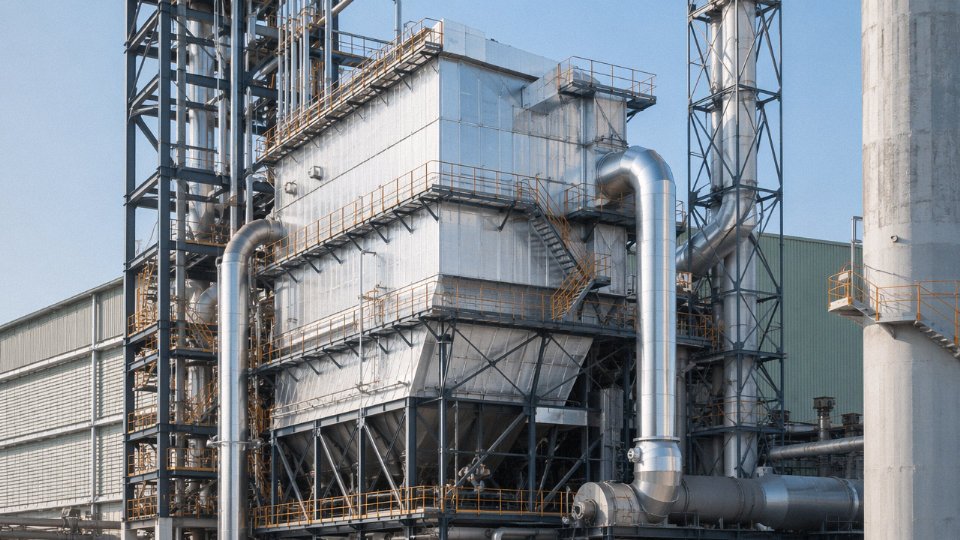
Drop the inlet gas temperature to the 300–500°C band — typical of cement kiln preheater outlets or coke oven waste gas — and the thermodynamics constrain you to saturated or mildly superheated steam, generally 1.5–16 bar. That’s perfectly suited for process heating loads, absorption chiller driving, or low-pressure condensing turbines. It’s not glamorous, but a cement plant recovering heat from its preheater and raw mill exhausts simultaneously can offset a meaningful share of its auxiliary power consumption. The engineering challenge here is usually dust loading and the pinch point: cement kiln gas often carries 30–80 g/Nm³ of fine dust, which dictates wide tube pitch, sootblower design, and sometimes a dedicated dust hopper below the tube banks.
Low-Temperature Recovery: Below 250°C
Below roughly 250°C — diesel engine jacket water recovery, compressor intercooling, low-grade process exhausts — you’re usually not generating steam at all in any practical sense. The sensible path is hot water generation or a thermal oil circuit. Thermal oil WHRBs in the 200–350°C range are genuinely useful here: they operate at low gauge pressure (typically under 1 MPa even at 300°C fluid temperature), eliminate the statutory inspection burden that comes with high-pressure steam systems in many jurisdictions, and give process engineers precise temperature control for heat-sensitive applications like rubber vulcanization or chemical reactors. The tradeoff is fluid degradation over time — thermal oil needs periodic sampling and eventual replacement, which is an ongoing cost fired-boiler operators sometimes overlook when comparing the two configurations.
Drum Design and Circulation: It Affects More Than You Think
Natural circulation single-drum designs work well when space permits and gas temperatures are stable. Forced circulation becomes necessary — or at least strongly preferable — when steam pressure exceeds roughly 100 bar (natural circulation driving head becomes marginal), when the gas duct geometry is awkward, or when a retrofit project has tight footprint constraints. Once-through designs appear in very high-pressure applications, essentially eliminating the drum but demanding precise feedwater quality control. Choosing wrong here isn’t catastrophic on day one; it shows up as circulation instability, tube overheating, or chronic steam quality problems months into operation.
Where Fired Boilers Still Have the Edge
A well-designed coal-fired or gas-fired boiler can produce steam at up to roughly 540°C and 300 bar in supercritical utility configurations. That flexibility — the ability to hit any pressure-temperature target independent of a heat source — is the fired boiler’s genuine structural advantage. WHRBs are bounded by source gas temperature, full stop. A plant with a 350°C exhaust gas stream cannot generate 100-bar superheated steam from it regardless of how the WHRB is engineered. This is why application matching isn’t just an engineering nicety; specifying a WHRB beyond what its heat source can support leads to chronic underperformance and frustrated operators.
WHRBs in high-temperature applications (500–1,100°C inlet gas) can produce superheated steam at 40–130 bar and 400–540°C, suitable for steam turbine power generation.True
Gas turbine HRSGs and industrial furnace WHRBs routinely achieve these conditions when inlet gas temperature and flow rate are sufficient; steam parameters are thermodynamically bounded by source gas enthalpy, not boiler design limits alone.
The practical takeaway for engineers selecting equipment: characterize your exhaust gas stream thoroughly — temperature profile across the operating day, flow rate at minimum and maximum production, dust and chemical composition — before any WHRB configuration is fixed. A heat balance calculated on nominal conditions that never actually occur in the plant is a very common source of disappointment on commissioning day.
Integration with Upstream Processes, Gas Turbines, Engines, and EPC Project Configuration
A waste heat recovery boiler is not a drop-in appliance. It is a system component, and that distinction matters enormously when you are scoping an EPC project or evaluating bids from equipment suppliers. A conventional fired boiler sits at the end of a fuel line and a water line and largely minds its own business. A WHRB, by contrast, is tightly coupled to whatever upstream process is generating the hot gas — and if that upstream process hiccups, the boiler has to respond or you risk a pressure excursion, a drum level upset, or a forced shutdown that cascades back into production.
Gas Turbine HRSG Integration
The most heavily engineered version of this coupling is the combined-cycle or CHP configuration where a gas turbine exhaust feeds a heat recovery steam generator. Typical exhaust conditions run 450–560°C at volumetric flows anywhere from 100,000 to 500,000 Nm³/h, depending on turbine frame size and ambient temperature — and ambient temperature matters more than people expect, since a hot summer day can drop turbine output by 10–15% and shift the exhaust enthalpy profile enough to affect drum pressure stability.
Standard scope for this configuration includes an inlet duct burner for supplementary firing (useful when steam demand exceeds what the turbine exhaust alone can supply), a diverter damper that allows the turbine to run while the HRSG is bypassed during startup or maintenance, and a steam turbine connection if you are going full combined cycle. Multi-pressure designs — typically two- or three-pressure levels — are common because they squeeze more energy out of the flue gas temperature gradient. The control logic has to coordinate turbine load signals, HRSG drum levels across multiple circuits, and steam turbine admission valves simultaneously. That is not something you hand to a generic PLC integrator unfamiliar with boiler dynamics.
Reciprocating Engine WHR: Two Heat Streams, One System
Reciprocating engines are a different challenge. The exhaust gas comes out at 350–500°C, which is workable for a conventional WHRB circuit. But engines also reject significant heat through jacket water cooling at 80–95°C — and if you ignore that stream, you are leaving roughly 20–25% of the fuel’s energy on the table. A properly configured engine WHR system recovers both streams simultaneously: a flue gas boiler for steam or high-temperature hot water, plus a jacket water heat exchanger feeding a lower-temperature circuit for space heating, absorption chilling, or process preheat. Total energy utilization climbs from roughly 40% electrical efficiency to 80–85% combined — a figure that completely changes the economics of the installation.
Kiln and Furnace Integration: Managing Gas Flow Variability
Cement kilns and steel reheating furnaces introduce a different kind of problem: gas flow variation. A cement kiln’s exhaust shifts with raw material feed rate and clinker chemistry. A steel furnace has tapping pauses where gas flow drops sharply. The WHRB design has to accommodate this through adequate steam drum volume for pressure buffering and bypass dampers that protect the boiler during low-flow or high-dust events. Undersizing the drum is a mistake I have seen bite projects more than once — the pressure swings become unmanageable and the downstream process ends up seeing unstable steam headers.
For dust-laden gases from kilns or incinerators, sootblowing systems are not optional. Fly ash accumulation on heat transfer surfaces degrades performance faster than most budget models assume.
Auxiliary Equipment Scope
A complete WHRB system is considerably more than the pressure vessel. A realistic auxiliary scope includes feedwater pumps and deaerator, chemical dosing and blowdown systems, steam headers with pressure-reducing stations, bypass stack with damper, and full instrumentation wired into the plant DCS. Omitting any of these from early project scope creates expensive change orders later.
A WHRB supplier offering full EPC scope — boiler, auxiliaries, civil, piping, electrical, and commissioning — reduces coordination risk compared to multi-vendor procurement.True
Single-responsibility EPC contracts eliminate interface disputes between boiler, civil, and electrical contractors, which are a documented source of project delays and cost overruns in industrial plant projects, particularly for overseas owners managing remote construction sites.
EPC capability matters especially for overseas plant owners who cannot easily manage five or six separate subcontractors across different technical disciplines and time zones. Cement plant WHR power generation projects (typically 5–15 MWe), coke dry quenching boilers in steel plants, glass furnace WHR, gas engine CHP, and waste incineration boilers each represent distinct scopes with different pressure levels, gas compositions, dust loadings, and regulatory requirements. A manufacturer who has executed all of these — not just quoted them — brings commissioning experience that generalist contractors rarely can.
Common Engineering Challenges in WHRB Projects and How Proper Design Avoids Them
Anyone who has commissioned a waste heat recovery boiler knows the gap between a well-engineered installation and a problematic one shows up fast — usually within the first operational year, sometimes the first month. The thermodynamic case for WHRBs is solid, but the engineering execution is genuinely harder than a conventional fired boiler. No burner to modulate, no fuel valve to trim — you take the gas as the upstream process gives it to you. That constraint puts all the burden on design-stage decisions.
Dust Fouling and Tube Erosion
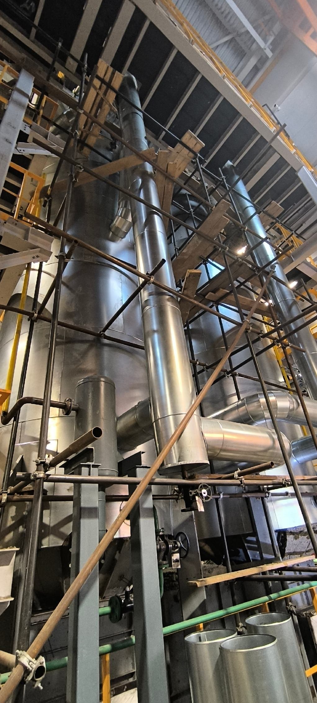
Flue gases from cement kilns, steel reheating furnaces, and biomass combustors routinely carry particulate loadings in the 20–80 g/Nm³ range, depending on upstream process control and the presence (or absence) of upstream dedusting equipment. Finned tubes, which are excellent for clean gas streams from gas turbines, become clogged rapidly in these environments. Bare tube evaporator sections are the correct specification for heavily dust-laden applications. Tube pitch and arrangement matter too — a wider transverse pitch reduces bridging and allows sootblowing jets to actually reach the tube surface rather than being blocked by accumulated ash bridges.
Hopper geometry is frequently underengineered. A hopper with insufficient slope angle — anything below roughly 55–60° depending on the ash bulk density — will retain material and eventually collapse a load onto the tube bundle. It sounds basic, but I’ve seen it go wrong more than once.
Acid Dew Point Corrosion
Sulfur-bearing fuels and processes introduce SO₂ and SO₃ into the flue gas. SO₃ in particular reacts with moisture to form sulfuric acid vapor, which condenses on cold metal surfaces — typically economizer tubes — when the local wall temperature drops below roughly 130–150°C, though the exact dew point shifts depending on SO₃ concentration and moisture content. Getting this wrong destroys economizer tubes within two to three years.
Specifying the right tube material for the cold-end section is non-negotiable: weathering steel grades (including Corten-type alloys) perform reasonably in mild cases, but for higher sulfur loadings, 316L stainless steel or specialist low-alloy steels are worth the premium. Equally important is building a minimum gas exit temperature setpoint into the control logic — one that’s maintained even during low-load conditions when gas mass flow drops and cold-end surface temperatures fall. This is a control system requirement, not just a materials question.
Maintaining flue gas exit temperature above the acid dew point is sufficient to prevent cold-end corrosion in all cases.False
Minimum gas exit temperature control reduces corrosion risk significantly, but local cold spots near feedwater inlet zones can still fall below dew point under certain transient conditions. Both material selection and temperature control are required together.
Thermal Fatigue from Cycling Operations
WHRBs coupled to intermittent processes — electric arc furnaces run in heats, batch glass kilns, some cement coolers — see temperature swings that a continuously fired boiler simply never experiences. The drum wall, nozzle connections, and header stub welds accumulate fatigue cycles. Drum thickness needs to be calculated with cycling life in mind, not just steady-state pressure containment. Startup rate limits (typically 1–3 bar/min depending on drum wall thickness and design pressure) should be locked into the DCS, not left to operator judgment. A 20-year service life is achievable, but it requires that these limits actually be respected — which means the automation needs to enforce them, not just recommend them.
Gas Flow Distribution
Industrial ductwork rarely delivers gas to a WHRB in a uniform velocity profile. Elbows, expansions, and transitions all create swirl and stratification. Where the velocity is highest, tube erosion accelerates; where it’s lowest, fouling accumulates. Inlet turning vanes and distribution baffles fix most of this. CFD modeling during duct design is cost-effective insurance — a few weeks of simulation work can prevent tube replacements that cost multiples of that. This is one area where skipping the analysis to save engineering budget reliably backfires.
Steam Quality During Load Transients
When the upstream process swings — an EAF going from full heat to tap-out, for example — the gas enthalpy input to the WHRB changes faster than the steam system can respond. Poorly sized steam drum internals allow moisture carryover into the steam header, which causes water hammer and damages downstream equipment. Adequately sized chevron driers and cyclone separators inside the drum, combined with properly tuned feedwater control valve response, handle most transient scenarios. The feedwater valve is often the weak point: a valve with too-slow response will cause drum level swings during rapid load changes that trip the unit.
Water Chemistry and Blowdown
Poor feedwater quality is, in my experience, the single most common cause of premature WHRB tube failure in the field. At operating pressures above roughly 40 bar, scaling becomes aggressive and the margin for chemistry upsets is narrow. Deaeration, continuous conductivity monitoring, and consistent chemical dosing (oxygen scavengers, phosphate programs) aren’t optional extras — they’re the difference between a 20-year asset and a five-year repair cycle.
A traditional fired boiler has one compensation mechanism that a WHRB lacks: you can back off the burner to reduce heat flux to a scaling tube and buy time. A WHRB takes whatever heat the upstream process produces. That makes design-stage water treatment specification and operator training on blowdown management more critical, not less.
| Challenge | Root Cause if Ignored | Design Countermeasure |
|---|---|---|
| Tube erosion (dusty gas) | Bare tube vs. finned tube mismatch | Bare tubes, wide pitch, sootblowing coverage |
| Cold-end corrosion | Gas exit temp below acid dew point | Material grade + minimum exit temp control |
| Thermal fatigue cycling | No startup rate enforcement | Drum thickness design, DCS rate limits |
| Uneven flow distribution | Inlet duct geometry | Turning vanes, distribution baffles, CFD |
| Steam carryover on transients | Undersized drum internals | Cyclone/chevron separators, tuned feedwater valve |
| Tube scaling / failure | Inadequate feedwater treatment | Deaerator, dosing, conductivity monitoring |
None of these are exotic problems. They’re all well understood in the industry. The projects that run into trouble are usually ones where the WHRB was treated as a commodity heat exchanger rather than a system-engineered piece of plant — specified on price, with insufficient attention paid to the upstream gas characteristics and the operating duty cycle. Getting the process data right before finalizing the design is worth more than any single materials upgrade.
Selecting the Right WHRB Configuration: Decision Framework for Plant Engineers and Procurement Teams
Getting the configuration wrong at the specification stage is expensive. A mismatched WHRB — undersized for actual gas volume, specified with finned tubes in a dirty cement kiln exhaust, or lacking supplementary firing when process steam demand is intermittent — will either underperform or require costly rework within the first operating year. The selection logic below is sequential for a reason: each step narrows the design space before you move to the next.
Step 1 — Characterize the Heat Source First, Not Last
Most misspecification problems start here. You need actual measured data, not nameplate estimates: exhaust gas volume flow in Nm³/h (corrected to standard conditions), inlet temperature range (not just peak), and — critically — the gas composition. O₂ content tells you whether supplementary firing is viable. SO₂ and H₂O together define acid dewpoint risk, which drives your minimum outlet temperature and tube material selection. Dust loading (g/Nm³) determines whether finned surfaces are even an option.
Sticky compounds deserve special attention. Alkali chlorides from biomass or waste combustion, tar aerosols from certain chemical processes, or condensable hydrocarbons will blind finned tube banks within weeks. If you see these in the gas analysis, plan for bare tubes and generous sootblower access from the start.
The availability profile matters as much as the temperature. A continuous gas turbine exhaust is a fundamentally different design problem from a batch glass furnace that cycles on and off every few hours. Cyclic sources impose thermal fatigue on drum connections and header welds that a steady-state boiler never experiences.
Step 2 — Pin Down the Steam or Heat Demand Before Sizing
Required steam pressure and temperature, expected load swing (±10% or ±40%?), and whether the primary use is process heating or power generation via a steam turbine — these define the pressure/temperature envelope the WHRB must hit. If you need superheated steam above roughly 450°C for a back-pressure turbine, the superheater surface placement and material grade jump significantly in cost and engineering complexity. Hot water or thermal oil output is also an option for lower-temperature sources (typically below 450°C inlet), and for some process heating applications that path is simpler and cheaper than raising steam.
Step 3 — Match Drum Configuration to Gas Behavior
Natural circulation is the default for stable, continuous gas flows and covers the majority of industrial installations. It is simpler to operate, easier to maintain, and tolerates modest fluctuations well. Forced circulation becomes the better choice when footprint is constrained (the compact tube bundle geometry it allows) or when gas temperature varies widely and rapidly — the controlled coolant flow prevents steam stratification and departure from nucleate boiling under transient conditions. Once-through designs are reserved for high-pressure supercritical applications above roughly 220 bar; you will not encounter these in most industrial plants outside utility-scale combined cycle projects.
Step 4 — Tube Surface and Material Selection
| Gas Condition | Recommended Surface | Typical Material | Notes |
|---|---|---|---|
| Clean (turbine/engine exhaust, 200 mg/Nm³) | Bare tubes, erosion shields at inlet | Alloy steel inlet section | Replaceable wear plates at first pass |
| High temperature >900°C inlet | Membrane wall radiant section + convective bare tubes | 15CrMoG or higher | Radiant section absorbs peak flux before convective bank |
| Acidic condensate risk (SO₂ + H₂O) | Bare tubes, enamel or Corten at cold end | Weathering steel or 09CrCuSb | Keep outlet gas temp >acid dewpoint |
Step 5 — Decide on Supplementary Firing Early
If process steam demand exceeds what the exhaust gas alone can supply at minimum load — or if steam must be maintained during planned or unplanned upstream outages — you need a duct burner system. Size it for the actual shortfall, not the maximum conceivable gap, or you end up with an oversized burner that runs at part-load constantly and loses efficiency. This is also the economic crossover point: if supplementary firing covers more than roughly 40–50% of total heat input on a regular basis, the case for a dedicated fired boiler running in parallel (with the WHRB handling base load) deserves a fresh cost comparison.
A properly sized duct burner on a WHRB can maintain rated steam output during upstream process shutdowns without a separate standby boilerTrue
Duct burners firing into the WHRB gas path can compensate for reduced or absent exhaust heat, provided the WHRB pressure parts and steam drum are rated for the resulting duty. This is standard practice in cement and glass plant configurations with single-pressure natural circulation HRSGs.
Step 6 — Site Constraints Often Override Optimal Design
Horizontal gas flow layouts (the exhaust enters the side, travels horizontally through the tube banks) generally give better access for cleaning and inspection and suit ground-level installations. Vertical upflow arrangements suit tighter footprints but complicate sootblower installation and ash removal. Check available headroom before committing to a vertical configuration — it is a surprisingly common problem on retrofit projects where the existing structure was not designed for a tall boiler body.
Connection to an existing steam header requires pressure-matching and a proper check valve arrangement to prevent backflow during startup. If the site already runs a fired boiler on the same header, the control philosophy for managing two steam sources simultaneously needs to be specified early, not resolved during commissioning.
The table above covers most industrial selection scenarios. In practice, a cement plant kiln exhaust running at 350–400°C with high dust loading will land on bare tubes with erosion protection and a natural circulation drum; a gas turbine HRSG at 520°C clean exhaust will use multi-pressure finned tube banks. Those two projects share a category name but almost nothing else in their engineering content.
Frequently Asked Questions About Waste Heat Recovery Boilers vs. Traditional Boilers
Can a WHRB completely replace my fired boiler?
In plants running continuous, high-temperature process exhaust — cement kilns, glass tank furnaces, steel reheating lines, gas turbine power blocks — a properly sized WHRB can cover 100% of base steam demand without any supplementary firing. That said, most experienced engineers recommend keeping either a small fired backup boiler or a duct burner in the exhaust duct for startup, planned maintenance periods, and peak demand spikes. Primary fuel consumption still drops by 70–100% of what the fired boiler was previously burning. The realistic picture is that you’re running the fired unit maybe 200–400 hours per year instead of 8,000. That’s a fundamentally different cost profile.
A waste heat recovery boiler can supply 100% of a plant's base steam demand in applications with continuous high-temperature process exhaust above 400°C.True
In continuous-process industries such as cement, glass, and combined-cycle power, WHRB systems are routinely designed as the sole steam source for base load, with supplementary firing or backup units reserved for transient conditions only.
What exhaust temperature is actually needed to make a WHRB worth building?
The rough threshold most projects work from is a sustained inlet gas temperature above 250–300°C at adequate volumetric flow. Below that, a full WHRB with superheater, evaporator, and economizer sections is often hard to justify economically — you might be better served by an economizer-only feedwater preheater or, in some cases, a heat pump arrangement. The key word is sustained. Intermittent high-temperature exhaust from batch furnaces can still work, but the design gets more complicated and the payback period stretches. Gas volume matters as much as temperature; a 280°C stream at 150,000 Nm³/h may recover more usable heat than a 500°C stream at 8,000 Nm³/h.
How does service life compare to a conventional fired boiler?
A well-designed WHRB in a clean-gas application — behind a gas turbine or a natural gas engine, for instance — will routinely see 25–30 years of service life, sometimes longer if tube inspection programs are followed. That’s actually longer than many field-fired coal or oil boilers, where fireside corrosion and slagging take a steady toll. The caveat is aggressive duty: high-dust exhaust from rotary kilns or waste incinerators accelerates tube erosion and requires planned tube replacement every 8–12 years depending on ash loading and particle hardness. Factor that into your lifecycle cost model upfront, not after the first outage.
Is a WHRB harder to operate than a fired boiler?
You lose burner management complexity entirely — no flame monitoring, no combustion air ratio trimming, no fuel train valve sequencing. What you gain instead is process-coupling logic: the boiler output follows whatever the upstream process is doing, and the control system has to manage load swings passively rather than actively adjusting firing rate. Modern DCS platforms handle this well, and operator training requirements are broadly comparable to fired boiler operation. In practice, operators often find WHRBs less stressful to run day-to-day, though they need a good understanding of what the upstream process is doing and why.
What certifications apply for export or EPC projects?
Standard pressure vessel and boiler codes govern WHRBs the same way they govern any steam-generating equipment. For North American projects, ASME Section I is mandatory. European supply follows EN 12952 (water-tube boilers) or EN 12953 (shell boilers) depending on configuration. China-manufactured equipment for export is typically built to GB/T standards and carries SELO certification, which is the recognized export quality mark for boiler and pressure vessel products. Third-party inspection — Bureau Veritas, TÜV, Lloyd’s, SGS depending on the end-client requirement — plus full material traceability documentation and hydrostatic test records are standard deliverables in any properly structured EPC export package.
Can an existing plant retrofit a WHRB alongside operating equipment?
Yes, and it’s done regularly. The engineering checklist for a retrofit is fairly predictable: confirm available exhaust gas heat content under real operating conditions (not nameplate), verify structural capacity for new ductwork and boiler weight, check whether the existing steam header pressure matches what the WHRB can deliver, and audit feedwater system capacity and water treatment setup. The ductwork tie-in is usually the most disruptive part of construction, since it often requires a planned shutdown of the upstream process. Budget two to four weeks for the tie-in outage, depending on plant layout — though some retrofits have been completed over a long weekend with careful prefabrication.
How does a thermal oil WHRB differ from a steam system?
Thermal oil heat recovery systems operate at pressures close to atmospheric regardless of the fluid temperature, which can reach 300–350°C in standard mineral oil systems and somewhat higher with synthetic fluids. That low-pressure operating characteristic removes the statutory inspection requirements and operator licensing obligations that high-pressure steam systems carry in most jurisdictions. For smaller plants — a food processing facility, a wood-drying operation, a chemical batch plant — this is a meaningful practical advantage. Steam delivers better heat transfer coefficients and is generally preferred where you need to generate power or where the process already uses steam. Thermal oil wins where the process needs precise temperature control in the 150–320°C band without the regulatory overhead of a pressure system.
References
- Industrial Waste Heat Recovery Basics and Efficiency Benefits
Source: U.S. Department of EnergyWaste Heat Recovery Technology and Opportunities in U.S. Industry
Source: U.S. Department of EnergyWaste Heat Recovery Technology Assessment
Source: U.S. Department of EnergyGuide to Combined Heat and Power Systems for Boiler Owners and Operators
Source: U.S. Department of EnergyCombined Heat and Power Efficiency, Cost and Emissions Benefits
Source: U.S. Environmental Protection AgencyWaste Heat-to-Power Technologies, Applications and Economics
Source: U.S. Environmental Protection AgencyHow Heat Recovery Improves Gas Turbine Power Plant Efficiency
Source: U.S. Department of EnergyHow Combined-Cycle Plants Generate Power From Turbine Exhaust
Source: U.S. Energy Information AdministrationWaste Heat Reduction and Recovery for Industrial Furnaces
Source: U.S. Department of EnergyWaste Heat-to-Power Systems Without Additional Fuel
Source: U.S. Department of Energy Better Buildings Solution Center