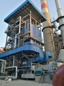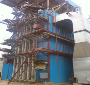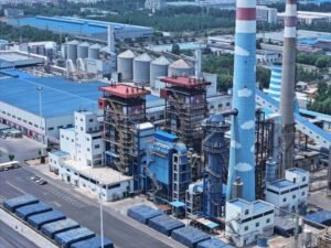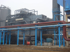
Sending 400–600°C exhaust straight up a stack is not just an inefficiency — it is a recurring cost that compounds every operating hour. Plants running open-cycle gas turbines or unrecovered industrial kilns routinely leave 30–45% of their fuel energy in the flue gas, and that shows up directly in fuel bills, carbon exposure, and competitive unit costs. When energy prices spike or carbon levies tighten, those plants feel it first.
A waste heat recovery boiler — commonly called an HRSG (heat recovery steam generator) when paired with a gas turbine — captures exhaust gas energy that would otherwise be lost to atmosphere, converting it into usable steam or hot water for power generation, process heating, or both. Thermal recovery efficiency typically ranges from 80% to 92%, depending on exhaust temperature, configuration, and whether supplemental duct firing is used. In combined-cycle plants, this single piece of equipment is largely responsible for pushing overall plant efficiency from the 33–42% range of simple-cycle operation up to 55–62%.
What makes the engineering genuinely interesting is how much performance depends on decisions made early — pinch point margins, pressure levels, the choice between single- and multi-pressure drums, supplemental firing, and how the boiler integrates with whatever heat source sits upstream. Get those calls right and you recover heat efficiently for 20-plus years. Get them wrong and you either leave money on the table or spend it on tube failures and chemistry problems you did not see coming.
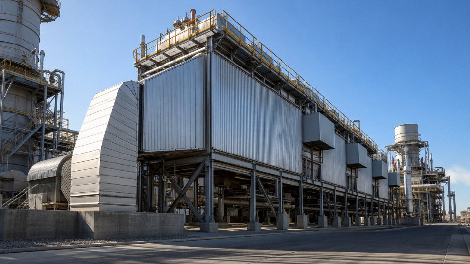
How Gas Turbine HRSG Systems Work: Thermodynamic Principles and Heat Transfer Mechanics
The fundamental setup is a cascade of two thermodynamic cycles sharing a common interface — the HRSG itself. The gas turbine operates on the Brayton cycle: compress air, combust fuel, expand hot gas through the turbine. That expansion produces shaft power, but the exhaust leaving the turbine still carries substantial enthalpy — typically at 450–620°C depending on turbine model, ambient conditions, and load. Without an HRSG, that thermal energy exits the stack and is gone. The Rankine steam cycle downstream recovers it: exhaust gas heats feedwater into steam, steam drives a steam turbine, condenser returns condensate, and the loop repeats. Neither cycle is exotic on its own; the engineering challenge is the thermal handoff between them, which is where pinch point and approach temperature become critical design levers.
Pinch Point and Approach Temperature: The Designer’s Real Trade-Off
The pinch point temperature difference (PPTD) is defined as the gap between the exhaust gas temperature leaving the evaporator section and the saturation temperature of steam at the operating drum pressure. In practice, designers target 8–15°C. Tighten that to 5°C and you recover more heat but the required evaporator surface area climbs sharply — and so does capital cost. Widen it to 20°C and the surface shrinks, but you leave recoverable energy on the table for the life of the plant. The approach temperature is a related parameter: it’s the difference between drum saturation temperature and the feedwater temperature entering the evaporator. Keeping this at 3–8°C prevents premature steam generation in the economizer (economizer steaming), which causes flow instability and accelerated tube erosion. In my experience, optimizing both values simultaneously against a project’s fuel cost and capital budget is where real HRSG design expertise shows — there’s no universal answer.
Sequential Heat Transfer Sections from Gas Inlet to Stack
Gas enters the HRSG casing at the hot end and gives up heat progressively as it flows toward the stack. The section order matters. A duct burner, when installed, sits at the inlet before any tube bundles — it fires into the oxygen-rich turbine exhaust (typically 12–15% residual O₂) to boost enthalpy before heat exchange begins. Downstream come the superheater bundles, which raise saturated steam to the required turbine inlet temperature, often 450–560°C for high-pressure circuits. The evaporator follows: this is the largest section by heat duty, absorbing the latent heat of vaporization at constant pressure. The economizer sits further downstream, heating feedwater from condensate return temperature up toward drum saturation temperature — recovering useful energy from gas that has already dropped to 200–350°C. A condensate preheater at the cold end can extract another increment of heat, pushing stack exit temperature down to 90–120°C, though going below the acid dew point (around 120–140°C for sulfur-containing fuels, or as low as 90°C on clean natural gas) risks cold-end corrosion.
Single, Dual, and Triple-Pressure Configurations
A single-pressure HRSG is straightforward and cost-effective for smaller gas turbines or industrial steam applications where one steam header suffices. The limitation is thermodynamic: the exhaust gas temperature profile and the saturation curve at a fixed pressure don’t align well — a significant portion of available heat sits below the single-pressure evaporation threshold and exits the stack unreached.
Dual-pressure designs add a low-pressure (LP) circuit, typically 0.5–1.0 MPa, that scavenges heat from the cooler gas section below the HP evaporator. This alone can improve heat recovery efficiency by 4–8 percentage points compared to single-pressure, depending on exhaust temperature and HP steam pressure. Most combined cycle plants in the 50–200 MW class use dual-pressure as the default.
Triple-pressure reheat (TP-RH) configurations — with HP, intermediate-pressure (IP), and LP circuits plus a reheat leg — are standard on large combined cycle units above roughly 200 MW, where steam turbines are large enough to justify the additional complexity. HP steam pressures reach 12.5 MPa, IP around 2.8 MPa, LP at 0.5 MPa. Getting to 55–62% overall plant efficiency at that scale requires squeezing the exhaust gas temperature profile tightly, and triple-pressure reheat is how you do it. For smaller projects, the added capital cost and control complexity rarely pay back.
Natural Circulation, Forced Circulation, and Once-Through
Most HRSGs below roughly 10 MPa operating pressure use natural circulation: steam-water density differences drive flow through the evaporator tubes without pumps. It’s mechanically simple, tolerates variable load well, and fails gracefully under flow upsets. Forced circulation uses dedicated circulation pumps to maintain a defined steam quality in the evaporator, which allows more compact tube bundles and horizontal gas path arrangements — common in horizontally-oriented HRSGs where natural buoyancy is insufficient.
Once-through (Benson-type) designs eliminate the steam drum entirely. Feedwater enters one end of the evaporator tubes and exits as superheated steam from the other. This suits operating pressures above 12 MPa (approaching or exceeding the critical pressure of 22.1 MPa) where drum-based designs become impractical. Startup behavior is more demanding: without a drum acting as a thermal buffer, control systems must respond faster to load transients, and water chemistry control is tighter. Maintenance access is also different — no drum internals to inspect annually, but tube blockage events are harder to catch early.
A natural circulation HRSG is generally unsuitable for operating pressures above approximately 12 MPa because steam-water density differences become insufficient to maintain stable circulation at supercritical or near-supercritical conditions.True
As pressure approaches the critical point (22.1 MPa for water), the density difference between steam and liquid water diminishes toward zero, making buoyancy-driven natural circulation unreliable. Once-through or forced circulation designs are used instead above roughly 12 MPa.
Supplemental Firing and Its Real Effects
A duct burner added at the HRSG inlet can boost steam output by 40–80% above the unfired condition — useful when a single gas turbine feeds a process that has variable high-steam-demand periods. The physics work because turbine exhaust contains 12–15% residual O₂, enough to support combustion without additional air supply. What engineers sometimes underestimate: duct firing raises exhaust temperature entering the superheater, which can push tube metal temperatures beyond original design limits if the burner capacity is sized aggressively. It also increases flue gas mass flow and stack NOx. HRSGs equipped with selective catalytic reduction (SCR) systems downstream can still meet sub-10 ppm NOx targets, but the SCR must be sized for the fired case, not just the unfired baseline.
A rough but useful reference point: a 100 MW-class gas turbine with exhaust around 540°C at roughly 300 kg/s will produce somewhere in the range of 50–70 t/h of steam at 6–10 MPa from a dual-pressure HRSG, unfired. That range depends on pinch point selection, HP steam pressure, feedwater temperature, and ambient conditions — not a number to quote in a contract without a proper heat balance.
HRSG Equipment Architecture: Key Components, Materials, and Structural Configurations
An HRSG is not a simple heat exchanger. What you’re actually buying — and what procurement managers often underestimate until they’re reviewing a fabrication drawing package — is a pressure vessel system, a gas ducting system, a steam separation system, and an emissions control system all integrated into a single structure that may weigh several hundred tonnes and span 30–50 meters in length. Getting the specification right before issuing a bid package matters enormously.
Pressure Parts: Tube Bundles, Drums, and Headers
The heat transfer core consists of finned tube bundles arranged in banks — economizer, evaporator, and superheater sections, sequenced so the hottest gas contacts the hottest steam-side fluid. Material selection tracks the temperature gradient. Carbon steel SA-106B handles economizer and low-temperature evaporator duties without issue. Once you move into superheater zones where tube metal temperatures can reach 500–580°C depending on steam pressure and exhaust gas conditions, you need alloy steels: SA-213 T11 or T22 for intermediate duty, T91 for the high-temperature superheater in triple-pressure configurations running above roughly 500°C tube metal temperature. Using the wrong grade here is not a paperwork problem — it’s a creep failure waiting to happen, usually 18–36 months into operation when wall thinning becomes measurable.
Fins are either helically wound or longitudinally welded onto the base tube. Helical fins dominate because they’re cheaper to manufacture and handle differential thermal expansion more predictably. Fin geometry — height typically 10–25 mm, pitch translated to roughly 200–400 fins per meter, thickness 1.5–3 mm — directly sets the heat transfer surface area per unit length and the fouling tendency. Tighter fin pitch increases surface area but traps particulates in exhaust streams with any appreciable dust loading. For clean gas turbine exhaust, a fin density toward the upper end of that range is reasonable. For waste heat from a cement kiln or a steel reheat furnace, you want wider pitch, probably Corten or 409 stainless fins, and you’d better have a sootblowing provision designed in from the start rather than retrofitted later.
Headers collect and distribute steam-water mixtures between tube banks. Downcomers and risers form the natural circulation loop in drum-type designs — the density differential between cooler downcomer water and steam-laden riser mixture drives circulation without pumps, which is one reason drum-type HRSGs remain more maintainable than once-through designs in most industrial settings.
Steam Drum Internals and Steam Purity
Steam drum internals are easy to overlook in a specification and expensive to regret. Cyclone separators handle primary bulk separation; chevron demisters downstream catch the fine droplet carryover. The targets — silica below 20 ppb, sodium below 10 ppb in the steam — are not arbitrary. They protect steam turbine blades from deposition and stress corrosion. A drum specified with undersized cyclones to save cost will produce wet, contaminated steam that gradually destroys turbine blades worth orders of magnitude more than the savings. Chemical dosing connections and continuous blowdown nozzles need to be sized and positioned by someone who understands the water chemistry regime the plant intends to run, not left to the lowest bidder.
Horizontal vs. Vertical Gas Flow Configurations
Most large gas turbine HRSGs use horizontal gas flow — exhaust enters one end, exits the other, tube bundles hang vertically from top headers. This configuration simplifies natural circulation, allows modular shop fabrication in manageable sections (typically 4–6 meters wide per module, constrained by road and rail shipping limits), and makes the civil foundation straightforward. Vertical gas flow designs, where gas travels upward through horizontal tube bundles, suit tighter footprint sites and some industrial waste heat applications with smaller mass flow rates. They tend to require more careful attention to tube support design against flow-induced vibration.
Casing and Insulation Systems
The debate between cold casing and hot casing is worth having explicitly with your supplier. Cold casing — a double-skin outer shell with internal mineral wool or ceramic fiber insulation — keeps the structural steel cool, simplifies external maintenance access, and is the dominant approach for large combined cycle HRSGs. The outer skin stays close to ambient temperature, which matters for personnel safety and reduces structural thermal stress. Hot casing, with external insulation applied over a single-skin pressure boundary, is simpler to fabricate and costs less, but the structural steel operates at elevated temperature and thermal expansion management becomes a more serious design exercise. Heat loss through casing typically runs 0.5–1.5% of total heat input — not dramatic, but worth specifying insulation quality explicitly rather than accepting whatever the supplier defaults to.
Bypass Stack and Diverter Damper
The bypass stack and diverter damper system is infrastructure that plant operators frequently wish they had paid more attention to during procurement. When the HRSG is offline for maintenance or during cold startup, the gas turbine needs somewhere to exhaust — the bypass stack handles that. The diverter damper redirects flow between the HRSG inlet and the bypass stack. Leak-by specifications matter: a poorly sealing damper allows hot gas to bypass continuously, creating a temperature excursion risk in the bypass duct and reducing combined cycle efficiency. Damper designs rated for full exhaust temperature (450–620°C) with less than 1–2% leak-by at design differential pressure are achievable; require that in the specification or you will get something cheaper that underperforms.
SCR and Oxidation Catalyst Integration
SCR systems for NOx reduction and oxidation catalysts for CO burnout are now standard in most regulated markets. Placement within the HRSG gas path is not arbitrary — the SCR catalyst requires a gas temperature window of roughly 300–400°C to function efficiently, which typically positions it between the high-temperature superheater outlet and the evaporator section. Placing it too early exposes the catalyst to excessive temperature; too late and you’re below the activation threshold, especially at part load. With a properly integrated SCR and ammonia injection grid, stack NOx levels below 10 ppm at 15% O₂ are achievable, which satisfies IFC/World Bank guidelines and EU IED requirements for most industrial classifications.
HRSG SCR systems can reduce stack NOx to below 10 ppm at 15% O2 when correctly sized and positioned in the gas pathTrue
This is consistent with published IFC Environmental, Health, and Safety Guidelines and demonstrated performance data from operating combined cycle plants using urea or ammonia injection SCR systems placed in the 300–400°C gas temperature window.
One practical note: ammonia slip from an oversized or poorly controlled SCR is a real operational problem — downstream ammonium bisulfate deposition on cold-end surfaces, particularly the gas-gas heat exchanger or economizer, can cause plugging and corrosion. The SCR control system needs to be integrated with the HRSG control logic, not bolted on as an afterthought.
Industrial Process WHRB Applications Beyond Gas Turbines: Cement, Steel, Glass, Engines, and Waste Incineration
Gas turbines get most of the attention in HRSG literature, but the honest reality on the plant floor is that some of the most compelling waste heat recovery opportunities sit in cement kilns, steel converters, and waste incinerators — processes that run around the clock and throw enormous heat volumes into the atmosphere without a second thought. The economics are often better than in combined-cycle power, precisely because the heat source is a byproduct of a process the plant is running anyway.
Cement Plant Waste Heat Power Generation
A 1 Mt/year clinker line produces two distinct recoverable exhaust streams: preheater/precalciner exit gas at roughly 300–380°C and clinker cooler vent air at 250–400°C, the latter depending on cooler design and ambient conditions. These feed a suspension preheater (SP) boiler and an air-quenching cooler (AQC) boiler respectively. Together, a well-integrated system typically generates 6–10 MW of electricity per million tonnes of annual clinker output, with no supplemental fuel. The dust loading in both streams is high — SP gas can carry 60–100 g/Nm³ of raw meal dust — so the boiler tube arrangement and sootblower spacing are not standard HRSG practice. Wider tube pitch, vertical tube banks, and automatic rapping systems are common design requirements.
Steel and Metallurgical Industry Heat Recovery
Converter gas (LD/BOF) presents a very different challenge. The gas exits at 1,400–1,600°C and contains 60–70% CO by volume — meaning it carries both sensible heat and significant chemical energy from unburned combustibles. Converter gas boilers are designed either to combust the CO (wet suppression systems burn it; dry recovery systems capture it for reuse), and the WHRB on these units handles large swings in flow rate and temperature as each heat cycle progresses, roughly every 30–40 minutes. That intermittency drives the design toward heavy-duty membrane wall construction and careful thermal stress management.
Sintering cooler WHRBs are comparatively straightforward but still dusty. Electric arc furnace (EAF) exhaust recovery is less common than it should be, largely because EAF flue gas contains variable quantities of metallic fumes and the temperature profile is erratic. Where it has been implemented, the payback is usually acceptable at 3–5 years depending on electricity prices.
Glass Furnace Exhaust
Regenerative glass furnaces exhaust at 400–600°C, but the gas contains substantial SO₂ and fine particulate — a combination that creates aggressive acid dew-point corrosion risk in the lower-temperature sections of the boiler. Corten steel casing helps in the dew-point zones, stainless steel tube bundles (typically 316L or 321) are standard in the cold end, and operators who skip upstream electrostatic precipitation usually regret it within 18 months when tube erosion forces an unplanned outage.
Reciprocating Engine WHRB
Diesel and gas engines exhaust at 350–550°C with a pulsating flow character that puts mechanical stress on connections and tube-to-header joints. Expansion joints and flexible inlet ducting are not optional. A useful feature often overlooked in initial scoping: combining exhaust WHRB with jacket water heat recovery can push total heat utilization to roughly 80–85% of fuel input, which is genuinely impressive for a distributed generation package.
Municipal Solid Waste and Industrial Waste Incineration Boilers
MSW boilers handle flue gas entering the convection section at 850–1,100°C and laden with HCl, SO₂, dioxins, and alkali chlorides. Steam parameters are deliberately kept conservative — typically ≤4 MPa and ≤400°C — because pushing higher temperatures dramatically accelerates chloride-induced corrosion on superheater tubes. Inconel 625 or stainless steel weld overlay on superheater tube outer surfaces is standard practice for any reputable supplier. Cutting this corner to reduce capital cost is a predictable route to superheater replacement within 3–4 years of operation.
MSW boiler steam parameters are intentionally limited to control high-temperature chloride corrosion on superheater surfacesTrue
Chloride attack rates on carbon and low-alloy steel superheater tubes increase sharply above 400°C metal temperature; limiting steam conditions keeps tube wall temperatures in a safer range and extends tube life to acceptable inspection intervals.
Chemical, Petrochemical, and Biomass Applications
Reformer flue gas WHRBs, FCC regenerator waste heat boilers, and Claus unit tail gas coolers each demand individualized gas composition analysis before tube material and fin density can be fixed — the presence of H₂S, COS, or catalyst fines changes everything. Biomass plant integration is more benign by comparison, though exhaust from biomass dryers often carries moisture and terpene compounds that require attention to dew-point management and condensate quality before returning to the boiler feedwater circuit.
HRSG Performance Parameters: How to Specify Steam Output, Pressure, Temperature, and Efficiency for Your Project
Getting the specification right before you issue an enquiry saves months of back-and-forth and prevents the classic problem where three suppliers quote on three different machines and you can’t compare any of them. Here’s what actually needs to go into an HRSG datasheet.
Primary Input Data: What You Must Know Before Sizing Anything
The exhaust gas mass flow rate and inlet temperature are the two numbers that drive everything else. For industrial gas turbines the mass flow rate typically falls somewhere between 50 kg/s and 700 kg/s — where you land on that range depends entirely on the turbine model and load point, not on some average you can look up. Always specify at the turbine’s ISO base load condition and at your worst-case ambient (a 45°C summer day in a Gulf plant behaves very differently from a temperate European site). Inlet temperature for gas turbine exhaust usually runs 450–620°C; for reciprocating engines it’s lower, roughly 350–550°C.
Gas composition matters more than most procurement specs acknowledge. You need O₂%, CO₂%, H₂O%, and SO₂ in ppm — at minimum. The O₂ content determines how much supplemental firing is thermodynamically feasible, and SO₂ directly sets your stack temperature floor. A turbine running on pipeline natural gas with near-zero sulfur gives you flexibility to target a stack exit around 90–120°C. Switch to diesel or a refinery off-gas with 200–400 ppm sulfur and the sulfuric acid dew point climbs to 140–160°C, sometimes higher, and you cannot safely drop below that without risking cold-end corrosion on the economizer.
Allowable backpressure on the gas side is frequently underspecified. Every additional 1 kPa of pressure drop across the HRSG gas path costs roughly 0.3–0.5% of the gas turbine’s electrical output — and that penalty runs 8,000+ hours a year. On a 100 MW combined-cycle unit, that arithmetic adds up fast. Specify the maximum permissible total gas-side pressure drop explicitly; a realistic target is 1.5–4.0 kPa depending on configuration and number of pressure stages. Don’t let a supplier silently trade away your turbine output to squeeze in extra heat transfer surface.
Steam Output Parameters: Be Specific or Expect Surprises
State steam pressure in MPa gauge, not just “high pressure.” A single-pressure unit at 4 MPa(g) and a dual-pressure unit at 8.0/1.6 MPa(g) are completely different machines. Specify whether you want superheated or saturated steam, the superheat temperature in °C, and the minimum guaranteed steam flow in t/h at the design exhaust condition. Feedwater inlet temperature matters because it sets the economizer duty; a deaerator operating at 105°C versus one at 130°C changes the low-end surface area requirement meaningfully. Include blowdown rate — typically 1–3% of steam output for clean condensate return systems, higher if makeup water quality is poor.
Efficiency: How to Benchmark Supplier Claims
Thermal efficiency in an HRSG context means heat absorbed by the water/steam circuit divided by the total heat available in the exhaust gas above a reference temperature (usually 15°C or 25°C — confirm which reference the supplier is using, because it shifts the reported number noticeably). Realistic values run 80–92%, with the upper end requiring tight pinch and approach temperatures, multiple pressure levels, and possibly a condensate preheater. Be cautious of a supplier quoting 91% on a single-pressure unfired unit without showing you the temperature profile diagram.
Tighter pinch point temperatures (below 8°C) always improve HRSG efficiencyFalse
Pinch points below roughly 8°C do recover more heat but require disproportionately larger heat transfer surface, increasing capital cost and sometimes making the project uneconomical. The optimum pinch temperature depends on fuel cost, steam value, and capital budget — it's a site-specific trade-off, not a universal rule.
Stack exit temperature is the most honest single proxy for efficiency in the field. You can verify it with a thermocouple. You can’t easily verify calculated effectiveness claims without a full instrumented test.
Duct Burner Specification and NOx Implications
If your process demands more steam than the unfired HRSG can produce — peak winter heating loads, for instance, or process upsets — a duct burner allows supplemental firing up to roughly 850–950°C maximum duct gas temperature (constrained by casing and tube material limits). Specify fuel type, maximum and minimum firing rate, and required turndown ratio. A 4:1 turndown is common; some applications need 8:1 or better. Natural gas is straightforward. Refinery gas with variable Wobbe index requires more careful burner management and adds cost to controls.
Duct firing consumes the residual O₂ in the turbine exhaust, which typically runs 13–16% — plenty of oxygen to support supplemental combustion without an external air supply. NOx from the duct burner can push stack emissions above permit thresholds; if you’re targeting below 10 ppm NOx at 15% O₂ (IFC/World Bank standard), you’ll need SCR with ammonia or urea injection downstream of the superheater, plus CO catalyst. Specify this requirement upfront — retrofitting SCR to an HRSG that wasn’t designed for the catalyst housing is expensive and sometimes physically impossible in the original plot area.
Availability and Reliability Targets
Design life is typically 25–30 years; annual operating hours should target above 8,000 for most continuous-process applications. To support that, the specification should explicitly require tube inspection ports at each module, online chemical dosing connections, continuous and intermittent blowdown with automatic control, redundant drum level transmitters (at least two independent measurement technologies on the HP drum), and access lanes wide enough for tube bundle withdrawal. These items sound obvious until you receive a stripped-down proposal that omits all of them to hit a price point.
Selecting the Right WHRB Configuration: Decision Criteria for Gas Turbine, Engine, Furnace, and Retrofit Projects
The single biggest mistake I see in WHRB projects is selecting a configuration based on what the boiler supplier has on the shelf, rather than working backward from the actual exhaust conditions and steam end-use. Getting that sequence right saves money at every stage — capital, installation, and the ten-plus years of operating cost that follow.
Exhaust Gas Temperature Is the First Filter
Start here, before anything else. Below roughly 300°C, you are not going to generate useful steam economically. The practical option is either an economizer recovering heat into the feedwater circuit, or a hot-water WHRB supplying low-temperature process or space-heating loops. Don’t overengineer it.
From about 300°C up to 500°C — which covers most reciprocating engine exhausts, some cement cooler air streams, and older cogeneration gas turbines — low- or medium-pressure steam HRSG design is the natural fit, typically 0.5–2.5 MPa saturated or lightly superheated. If the site has no steam use at all, an organic Rankine cycle (ORC) power block mated to the WHRB can convert that heat to electricity, though ORC capital costs are higher and cycle efficiency is modest; it usually makes sense only where grid power is expensive and steam has no takers.
The 500–700°C band is where most industrial gas turbine and large engine projects land. Here you can justify a high-pressure superheated steam configuration — 6–12.5 MPa, superheated to 450–540°C depending on your turbine spec — and extract meaningful power or process value. Pinch and approach temperatures matter a lot in this range; a pinch point of 8°C versus 15°C can shift steam output by 5–8% but adds meaningful surface area and cost.
Above 700°C — cement kiln string, glass tank exhaust, electric arc furnace offgas — you must put a radiant pass or refractory-lined settling chamber ahead of the convective tube bundle. Skipping this step burns out your leading tube rows in months. That is not a design conservatism; it is a repair bill.
Steam Destination Sets Your Pressure Level
| Steam end-use | Typical pressure range | Notes |
|---|---|---|
| Process heating, evaporation, sterilization | 0.3–1.6 MPa | Saturated usually sufficient |
| Back-pressure turbine power generation | 3–6 MPa | Requires superheating for turbine blade life |
| Condensing steam turbine combined cycle | 8–12.5 MPa | Multi-pressure HRSG, deaerator feedwater preheat |
| District heating or absorption chilling | 0.4–1.2 MPa | Saturation temperature drives heat exchanger sizing |
If your plant is already buying 1.0 MPa steam from a utility header for autoclave or jacketed vessel use, a WHRB generating at 1.2 MPa slides right into that loop with minimal tie-in work. Jumping to 6 MPa for a back-pressure turbine only pays back if your electricity tariff or avoided grid cost justifies the extra capital in the steam turbine island — usually a 5–8 year simple payback depending on running hours, fuel price avoided, and local power cost.
Site Constraints That Get Ignored Until They Bite
Altitude affects flue gas density more than most people budget for. A plant at 1,500 m elevation is working with roughly 85% of sea-level gas density, which means your draft calculation and any existing ID fan performance need re-checking before you commit to a stack height. Ambient temperature swings matter too — a plant in a continental climate seeing −25°C winters and +40°C summers needs freeze protection on the blowdown vessel and drum chemical dosing lines, and your deaerator must handle varying feedwater inlet temperature without hunting.
Footprint is a real constraint in brownfield installations. A horizontal natural-circulation HRSG needs 15–30 m of linear run depending on pressure level and steam output; a vertical forced-circulation unit can cut ground footprint by 30–40% at the cost of a circulation pump and slightly higher complexity. In my experience, plants that claim they have room for a horizontal unit often discover buried utilities or civil conflicts once excavation starts.
Seismic zone classification should be confirmed before the vendor draws the first support bracket. A horizontal HRSG with a 200-tonne operating weight on a high-seismic site in Southeast Asia is a structural engineering exercise, not just a process one.
Retrofit vs. Greenfield: The Constraints Are Different
Greenfield projects have the luxury of designing the gas turbine flange connection, exhaust duct layout, and HRSG together. Retrofit projects don’t. You inherit the existing stack height, the available pressure drop budget across the HRSG (typically 15–30 mbar for a gas turbine; exceeding it de-rates the turbine), and whatever deaerator and feedwater pump capacity was installed for the original configuration. Sometimes the existing deaerator is undersized for the new steam output; sometimes the feedwater pumps are fine but the piping is the wrong class.
A realistic retrofit project budget should include 2–4 weeks of machine downtime for duct cutover and tie-in, which concentrates minds wonderfully when planning the outage window.
Modular Shop-Fabricated vs. Field-Erected
Below roughly 30–50 t/h steam output, a modular shop-fabricated HRSG usually wins on total installed cost. Pressure vessels, headers, and tube bundles are assembled in the workshop, inspected under controlled conditions, and shipped as transportable modules. Road transport limits module width to about 4.5 m in most countries, and shipping weight typically caps at 50–80 tonnes per lift depending on port and crane access.
Above that threshold, field erection becomes cost-competitive and allows configuration flexibility that a shop-built unit can’t match — multi-pressure drums, large-bore bypass stacks, and integrated SCR or oxidation catalyst sections.
Shop-fabricated HRSG modules offer lower total installed cost than field-erected units for steam outputs below roughly 30–50 t/hTrue
Below this output range, the labor savings from controlled shop fabrication and reduced on-site civil and erection work outweigh the transport costs. Above it, shipping dimension limits and field labor rates in many regions make field erection competitive or cheaper on a cost-per-tonne-of-steam basis.
Auxiliary System Scope: Decide Early
Whether you buy the feedwater pumps, deaerator, chemical dosing skid, blowdown vessel, and steam separator as part of the WHRB package or supply them as owner-furnished equipment (OFE) affects your project schedule more than your budget. A packaged supply from one vendor simplifies integration and single-points the warranty, but locks you into that vendor’s preferred component brands. OFE gives you more control and sometimes better pricing on long-lead items like deaerators, but places interface coordination risk on your project team.
Capital cost for an industrial HRSG typically runs USD 200–600 per kW thermal — the low end for simple low-pressure units with clean exhaust, the high end for high-pressure multi-drum configurations with SCR, duct burner, and full instrumentation packages. Annual maintenance costs — tube ultrasonic inspection, chemical cleaning every 2–4 years, valve service, expansion joint replacement — generally run 1.5–3% of installed capital cost per year, which is worth modeling before you sign the purchase order.
Emissions Control, Water Treatment, and Regulatory Compliance for HRSG Operation
Running an HRSG cleanly is not optional — it is a condition of operating at all. Overseas project owners often underestimate how early in the design process emissions and water treatment decisions need to be locked in, and how expensive it is to retrofit SCR or CEMS hardware into a duct that was never sized for them.
Stack Emission Standards You Will Actually Encounter
The reference benchmarks most international lenders and EPCs work from are the IFC/World Bank Environmental Health and Safety Guidelines, which set NOx below 125 mg/Nm³ for gas-fired equipment in most industrial categories, though many projects now self-impose tighter limits to satisfy host-country regulators or project finance covenants. The EU Industrial Emissions Directive (IED) pushes combined-cycle plants toward NOx ≤ 50 mg/Nm³ and CO ≤ 50 mg/Nm³ on a daily average basis. US EPA 40 CFR Part 60 Subpart Db applies to steam generating units above roughly 29 MW heat input and specifies NOx, SO₂, and particulate limits that depend on fuel type and heat input tier.
In practice, a duct-fired HRSG burning natural gas is not a heavy emitter of SO₂ or particulate — the challenge is NOx and CO, and those two are somewhat in tension with each other during turndown. Know your applicable standard before specifying the burner management system.
SCR for NOx and CO Oxidation Catalyst
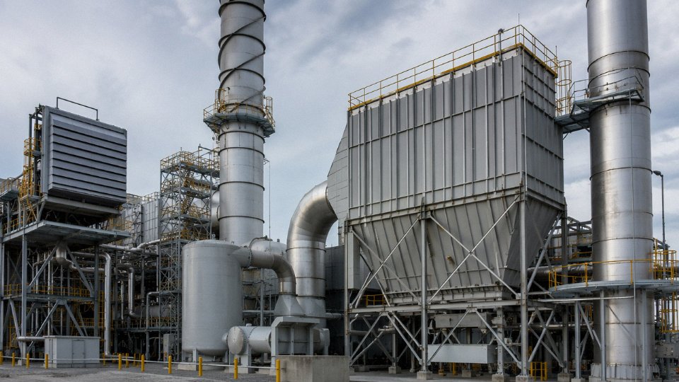
Selective catalytic reduction remains the dominant post-combustion NOx control technology for HRSGs. Aqueous ammonia or urea solution is injected through a grid of nozzles into the flue gas stream, and the reaction proceeds across a vanadium pentoxide or zeolite catalyst bed placed in the 280–420°C temperature window of the HRSG gas path — typically between the high-pressure evaporator and the economizer banks. Getting the catalyst into the right temperature zone requires close coordination between the HRSG thermal designer and the SCR vendor early in the project; shifting a catalyst bed location after the evaporator bundle geometry is fixed is a painful and expensive exercise.
Well-designed SCR systems on gas-fired HRSGs routinely achieve stack NOx below 10 ppm (at 15% O₂ reference). Ammonia slip — unreacted NH₃ escaping to stack — should be controlled to below 2 ppm; excess slip causes downstream ammonium bisulfate fouling and creates air permit problems.
SCR systems on gas-fired HRSGs can reduce NOx emissions to below 10 ppm at 15% O₂ reference conditions.True
This is achievable with properly designed SCR using vanadium pentoxide or zeolite catalyst in the 280–420°C temperature window, consistent with IFC/World Bank guidelines and demonstrated in combined cycle plant operations.
The CO oxidation catalyst — platinum-group metal, typically operating at 200–350°C — sits downstream of the SCR. It handles CO and VOCs, adds a pressure drop of roughly 25–50 Pa depending on face velocity, and carries a replacement interval of around 5–8 years depending on fuel sulfur content and operating hours. Budget for it as a capital line item in the lifecycle cost, not an afterthought.
CEMS: What the Regulators Actually Want
Continuous emissions monitoring systems are mandatory in most jurisdictions for units above certain heat input thresholds. A complete CEMS installation covers NOx, CO, O₂, stack flow, and temperature at minimum; some permits require SO₂ and opacity channels too. Data logging must feed into the plant DCS and produce audit-ready reports — the specific averaging period, data availability requirements (often 90–95% uptime of monitoring equipment), and reporting format vary by jurisdiction. In projects targeting EU or IFC compliance, factor CEMS procurement and commissioning into the critical path schedule. Calibration gas procurement is one of those details that gets ignored until startup.
Water Chemistry and Steam Purity
Water treatment inside the HRSG is where a lot of long-term corrosion damage originates, quietly. Treatment protocol selection depends on operating pressure and metallurgy. All-volatile treatment (AVT) — either reducing or oxidizing variant — is typical for drum-type HRSGs below roughly 12 MPa. Oxygenated treatment (OT) is used in some high-purity, all-ferrous once-through circuits. Phosphate treatment remains common for drum boilers in the 6–12 MPa range, though coordinated phosphate control requires careful attention to avoid hideout and caustic gouging.
Feedwater pH should be maintained in the 9.0–9.6 range; dissolved oxygen targets are below 7 ppb after deaeration. Iron transport is the early-warning metric — a sudden increase in iron concentration in the feedwater or steam condensate usually means something is wrong with either deaeration or chemistry control, and it will show up later as tube deposit and eventual under-deposit corrosion.
Blowdown and Discharge Compliance
Continuous blowdown on a drum HRSG typically runs between 0.5% and 2% of steam output, depending on feedwater quality and the steam purity specification. That blowdown stream is hot — 200°C or above at high pressure — and represents real recoverable energy. A blowdown heat exchanger feeding the deaerator or a low-pressure flash tank recovering blowdown steam to the LP header pays back in months on a reasonably loaded unit.
Before discharging blowdown water to drain or a treatment system, most jurisdictions require pH adjustment (typically 6–9) and cooling to below 40–60°C depending on local discharge consent conditions. Size the flash tank and blowdown cooler accordingly; an undersized cooler causes compliance failures during peak load.
Noise and Vibration
Flow-induced acoustic resonance in HRSG tube bundles is a real commissioning risk, particularly with finned tubes in narrow lane spacings at high gas velocities. Anti-vibration baffles and careful attention to tube support spacing at the design stage are far cheaper than field-installed dampers retrofitted after a resonance event damages fin welds. Duct burner combustion noise, particularly during ignition transients, and forced-draft fan aerodynamic noise both require acoustic treatment — lagged duct sections and inlet silencers on fans are standard practice. Permitting authorities in urban or peri-urban locations will impose noise limits at the site boundary, so obtain the acoustic assessment early and confirm it reflects actual operating load profiles, not just nameplate conditions.
Installation, Commissioning, Operation, and Maintenance Best Practices for Long Service Life
Getting an HRSG into service without cutting corners on pre-commissioning work is where most long-term reliability is won or lost. The plant floor reality is that construction debris — weld slag, mill scale, pipe dope, wire offcuts — ends up inside pressure parts regardless of how disciplined the construction contractor is. Before you ever light a gas turbine, that contamination has to come out.
Pre-Commissioning Chemical Cleaning and Hydrostatic Testing
Hydrostatic testing at 1.5× design pressure is a code requirement, but it also serves as a practical leak hunt before insulation goes on. Find your weeping socket weld now, not six months into operation when the casing is fully clad and scaffolding is long gone.
Chemical cleaning follows a defined sequence: alkaline degreasing (typically sodium hydroxide plus a surfactant, circulated at 80–90°C for several hours to strip hydrocarbon contamination from fabrication), acid pickling with inhibited hydrochloric or citric acid to dissolve mill scale and iron oxides, then a passivation rinse with sodium nitrite or hydrazine solution to lay down a protective magnetite film before the first steam raise. Skipping passivation because the schedule is tight is a decision that shows up later as elevated iron transport in the feedwater — which accelerates flow-accelerated corrosion (FAC) and eventually causes economizer tube failures. Not worth it.
Controlled First Steam Raise and Thermal Alignment
Heat-up rate during the first steam raise should be held to roughly 50–80°C per hour, and the lower end of that range is more conservative for thick-wall drums and large-bore headers. The physics here is simple: the outer surface of a thick ferritic drum heats faster than the bore, creating a temperature gradient that generates transient thermal stress. On units with drums above 80 mm wall thickness, exceeding the heat-up limit is how you initiate fatigue cracking that won’t show up in an inspection for two or three years.
Bolted flange connections on steam lines — particularly the turbine inlet flange — need to be re-torqued after the first thermal cycle. This is a standard step that field crews sometimes omit when they’re under pressure to achieve synchronization milestones. Mark it as a mandatory hold point in the commissioning procedure.
Normal Combined Cycle Startup Sequence
The typical automated startup sequence runs: gas turbine purge (air flow through the HRSG to clear any accumulated combustibles), ignition and controlled load ramp, exhaust temperature rise tracked against the HRSG heat-up curve in the DCS, pressure building in the LP and HP drums, steam bypass to the condenser via the bypass station while the steam turbine case warms, then steam turbine roll, warm-through, and synchronization. Modern DCS/PLC interlocks should enforce minimum drum level, maximum temperature ramp rate, and steam purity thresholds before the bypass station closes. If a plant is running on manual startup procedures for a unit this complex, that’s a risk worth discussing with the operators.
Online Monitoring Parameters That Actually Matter
Drum level measurement deserves redundancy — three independent measurement points is the industry-accepted minimum, using a combination of differential pressure transmitters and guided-wave radar on larger units. Single-point drum level is a common cost-cutting shortcut that has caused more forced outages than most plant managers want to admit.
Beyond drum level, the parameters worth trending continuously are steam temperature at the superheater outlet, gas-side draft loss across each heat transfer section (a rising trend indicates fouling or tube deformation), tube metal temperatures via embedded thermocouples on the hottest superheater rows, and blowdown conductivity as a proxy for cycle chemistry health. If conductivity is creeping up between blowdowns, you have a condenser tube leak or a makeup water treatment problem — find it before it becomes a stress corrosion cracking (SCC) event in your austenitic superheater elements.
Chloride concentration above approximately 0.5 ppb in boiler water significantly increases the risk of stress corrosion cracking in austenitic stainless steel superheater and reheater tubes.True
IAPWS and industry FAC/SCC guidelines consistently identify chloride ingress as a primary cause of SCC in austenitic alloys under operating stress and temperature. Condenser tube leaks in coastal or seawater-cooled plants are the most common source.
Tube Failure Mechanisms and How to Anticipate Them
FAC is the failure mode that catches operators off guard most often. It preferentially attacks economizer bends, feedwater heater piping, and drum internals in single-phase or two-phase flow under reducing water chemistry conditions — low pH, low dissolved oxygen, insufficient filming amine treatment. The damage is invisible on the outside until the wall is nearly gone. Periodic ultrasonic wall thickness measurement on known high-velocity bends, ideally during each annual inspection, is the only way to catch it before it becomes a rupture.
Erosion from entrained particulate is a different problem specific to process WHRB applications — cement kilns, glass furnaces, or solid fuel engines. Dust loadings in these exhausts can be orders of magnitude higher than a clean gas turbine exhaust. Lead tubes in the first few rows of the superheater, and any tube bends directly in the gas path, will thin faster than the rest of the bundle. In these applications, replaceable leading-edge erosion shields on tube rows and a more aggressive UT inspection interval — say, every 18 months rather than annual — are worthwhile precautions.
Planned Maintenance Schedule and Chemical Cleaning Triggers
A practical maintenance cadence looks roughly like this:
| Interval | Scope |
|---|---|
| Annual | Visual internal inspection, borescope of drum internals, valve seat check, blowdown valve function test, UT thickness on high-risk bends |
| Every 4 years | Tube sampling and destructive metallurgical examination, drum weld inspection (TOFD or phased array UT), refractory condition survey, safety valve overhaul |
| Condition-triggered | Chemical cleaning when iron transport exceeds ~10 ppb in feedwater or when gas-side pressure drop across an economizer section has risen more than 15% from baseline |
The 4-year tube sampling step is one that procurement managers sometimes push back on as an unnecessary cost. The counterargument is straightforward: a single tube failure that requires an emergency shutdown, pressure part repair, and re-hydrostatic test in a remote project location costs far more — in downtime revenue and mobilization of specialized welding crew — than the entire 4-year inspection budget.
Spare Parts Strategy for Overseas Projects
Long-lead pressure parts — drum-mounted relief valves, feed control valves, and finned tube replacement bundles in the most thermally loaded sections — need to be identified at the equipment supply stage and either warehoused on-site or secured with a committed delivery agreement. In practice, a finned tube bundle for a 60 MW HRSG is not something you source from a local distributor in 48 hours.
For overseas EPC projects, Taishan Group provides a first-fill spare parts list as part of the standard O&M documentation package, with full material traceability — mill certificates, heat numbers, and pressure part certificates — so that in-country regulatory inspections during replacement work don’t become bureaucratic delays. It’s the kind of documentation that seems unnecessary until the moment you actually need it.
Taishan Group’s HRSG and Waste Heat Boiler Manufacturing Capability, Certifications, and EPC Delivery
Sourcing an HRSG or process waste heat boiler is not purely a price exercise. Tube failures at 18 months, missing MTR documentation at customs, a supplier who disappears after shipment — these are the real risks that plant owners and EPC contractors get burned by. What follows is a direct account of what Taishan Group actually manufactures, how it is certified, and how projects get delivered.
Manufacturing Range and Pressure Envelope
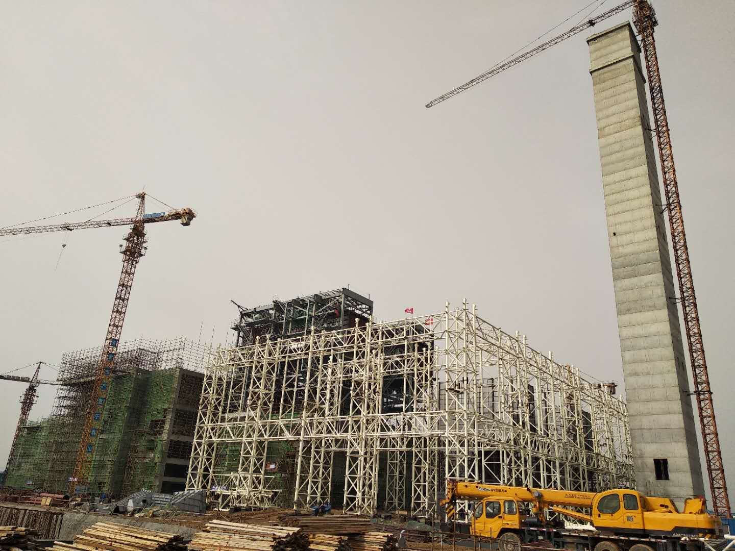
The fabrication scope runs from small shop-assembled horizontal units at roughly 5 t/h steam output up to large multi-pressure HRSGs producing 400 t/h, covering the full range from a single reciprocating engine exhaust application to a utility-scale combined cycle block. Design pressure spans 0.5 MPa saturated low-pressure steam systems all the way to 14 MPa superheat circuits, with steam temperatures up to 560°C — which puts the upper end squarely into the territory of high-alloy P91 headers and thick-wall drum forgings. Both horizontal natural-circulation and vertical forced-circulation configurations are in production scope, which matters because some industrial sites simply do not have the footprint for a horizontal layout.
Process industry WHRBs are a separate product line from gas turbine HRSGs and get treated accordingly: cement kiln exhaust systems handling gases above 700°C require different casing materials, expansion joint designs, and ash handling provisions than a clean gas turbine exhaust. Same goes for waste incineration WHRBs, where fireside corrosion from chlorine compounds is a genuine design constraint, not a footnote.
Code Compliance and Stamp Availability
For overseas projects, the stamping question comes up in every enquiry. ASME Section I (S stamp for power boilers) and Section VIII Division 1 (U stamp for pressure vessels) are available for clients specifying American or internationally recognized codes. EN 12952 applies for European and many Middle Eastern project specifications. GB/T 16507 covers domestic Chinese market supply. In practice, many Southeast Asian and African projects specify ASME as the baseline even when the local authority having jurisdiction is less prescriptive — it simplifies third-party inspection and insurance.
Taishan Group holds ASME S and U stamps for HRSG pressure parts manufacturingTrue
ASME S and U stamps are issued by ASME and maintained through regular audits; availability should be verified directly with Taishan Group and confirmed on the ASME certificate holder list before contract award
Quality Assurance and Third-Party Inspection
ISO 9001:2015 certification covers the manufacturing management system. More practically relevant for pressure equipment: full material traceability through MTR documentation traceable to the heat and lot number, weld procedure qualification per ASME Section IX (WPS, PQR, WPQ), and hydrostatic testing witnessed by an authorized inspection agency. TÜV, Bureau Veritas, Lloyd’s Register, and SGS have all conducted third-party inspection on Taishan equipment; owner-nominated inspectors are accommodated routinely. This is not unusual for a serious boiler manufacturer, but the documentation package — particularly MTRs and weld records — is where suppliers cut corners, and it shows up during owner audits or import inspections.
Auxiliary and Balance-of-Plant Scope
One coordination headache on HRSG projects is the steam-water auxiliary scope: deaerators, feedwater pumps, chemical dosing skids, blowdown vessels, steam separators, safety valve sets, and instrumentation packages. Taishan supplies these as part of the boiler island scope, which removes the interface risk between a boiler-only supplier and a separate BOP contractor. For smaller projects especially, having a single technical responsible party for the entire steam-water system from economizer inlet to steam header outlet simplifies both engineering and warranty management.
EPC Delivery Model
For clients who need more than equipment supply, the EPC scope includes front-end engineering design, detailed engineering documentation, civil and structural design packages, equipment supply, construction supervision, commissioning, operator training, and performance guarantee testing. This is applicable for independent power producer projects and industrial cogeneration schemes where the owner lacks in-house engineering capacity or wants a single contract interface. Commissioning and performance testing are done against agreed acceptance criteria — heat rate, steam output, exhaust temperature drop — not vague functional checks.
Overseas Project Experience and After-Sales Structure
Delivered projects span Southeast Asia, South Asia, the Middle East, and several sub-Saharan African markets. The practical experience that matters in those regions is less glamorous than the thermal design: familiarity with local import documentation requirements, packing specifications for long sea transit, coordination with local civil contractors who may not have worked with HRSG equipment before, and commissioning support in locations where the nearest spare parts warehouse is a week away. Remote diagnostics through DCS data connectivity are available for projects where the owner has online monitoring infrastructure. Pressure parts carry a 12-month warranty, and long-term service agreements covering scheduled inspections, tube sampling, and spare parts stocking are offered for clients who want to formalize the support relationship beyond the warranty period.
Frequently Asked Questions About [Waste Heat Recovery Boilers](https://coalbiomassboiler.com/product/waste-heat-recovery-boiler/) in Gas Turbine and Industrial Applications
What is the difference between an HRSG and a conventional fired boiler?
The fundamental distinction is the heat source. A conventional fired boiler burns fuel — gas, oil, coal, biomass — in a furnace, generating radiant and convective heat that transfers to bare tubes. An HRSG has no furnace. It intercepts hot exhaust gas from a gas turbine, engine, or industrial process and passes that gas across finned tube bundles sized specifically for low-temperature-difference heat exchange. Because the gas-side heat transfer coefficient is much lower than in a radiant furnace, finned tubes are essential to get adequate surface area without the unit becoming impractically large.
The two types serve complementary roles. Some installations combine them — a duct burner sitting upstream of the HRSG tube bundles supplements the exhaust heat when the turbine is at part load or when additional steam is needed. That configuration is still classified as an HRSG with supplemental firing, not a fired boiler, because the duct burner alone cannot sustain combustion without the oxygen-rich turbine exhaust stream carrying it.
What exhaust gas temperature is the minimum practical threshold for steam generation?
Roughly 250–280°C at the HRSG inlet is the practical floor for economical saturated steam generation at 0.5–1.0 MPa. Drop below that and the heat transfer driving force becomes marginal, the unit gets enormous for the steam it produces, and you start chasing the acid dew point of the exhaust — sulfuric acid condensation typically kicks in somewhere between 120°C and 160°C depending on fuel sulfur content, and that destroys economizer tubes fast if the feedwater inlet temperature is not managed carefully.
For superheated steam at 3 MPa and above, you really want inlet exhaust temperatures above 400°C. Below 200°C total, hot water recovery or an ORC (organic Rankine cycle) system makes more engineering sense than trying to generate steam.
Can a [waste heat recovery boiler](https://coalbiomassboiler.com/product/waste-heat-recovery-boiler/) be retrofitted to an existing gas turbine or engine?
Yes, and it happens regularly — aging simple-cycle peakers converted to combined heat and power, reciprocating engine plants adding heat recovery to improve overall fuel utilization. The critical checks before committing to a retrofit design are: exhaust duct flange dimensions and whether the existing transition piece can be modified; the draft budget, since an HRSG adds roughly 1.5–4 kPa of backpressure and that reduces gas turbine shaft output by approximately 0.3–0.5% per 1 kPa — meaningful over a year of operation; available site footprint, which is often the actual constraint on a congested plant; and whether existing feedwater pumps, deaerators, and condensate systems have spare capacity. A retrofit feasibility study using the turbine OEM’s correction curves is the only way to size these impacts properly rather than guessing.
How long does an HRSG typically last, and what drives early replacement?
A well-operated HRSG — meaning good water chemistry, controlled thermal cycling, regular tube thickness surveys — routinely runs 25 to 30 years. What cuts that life short is almost always one of three things: external finned tube corrosion from dew point attack in the cold end of the economizer (usually traceable to low feedwater inlet temperature or high exhaust sulfur), flow-accelerated corrosion in economizer carbon steel circuits running with insufficient feedwater pH or dissolved oxygen control, or creep damage in high-temperature superheater tubes if steam temperatures have been running above design for extended periods. Tube thickness ultrasonic monitoring every major outage and a disciplined water treatment program are not optional — they are the primary life extension tools available to an operator.
What is the typical lead time from order to delivery?
Shop-fabricated modular units in the 5–50 t/h range typically run 16–24 weeks ex-works, depending on pressure part complexity and whether finned tube manufacturing is in-house or subcontracted. Medium field-erected units in the 50–150 t/h range are more like 24–36 weeks. Large triple-pressure combined cycle HRSGs — the kind serving 100+ MW gas turbines — are 36–52 weeks for equipment supply alone. Add civil works, piping, electrical, and commissioning and an EPC project runs 6–18 months beyond equipment delivery, depending on site readiness.
HRSG equipment lead times for large triple-pressure units typically reach 36–52 weeks, exclusive of civil and commissioning scope.True
Large triple-pressure HRSGs involve extensive pressure part fabrication, high-alloy superheater materials, and complex multi-drum assemblies that require significant manufacturing queue time at any serious boiler manufacturer. This range is consistent with industry procurement practice.
Does an unfired HRSG require a fuel license and operator certification the same as a fired boiler?
An unfired HRSG does not need a fuel supply connection — no gas line, no burner management system — unless duct burners are included, in which case burner safety systems and fuel licensing requirements apply to that portion. However, the HRSG is still a pressure vessel generating steam, so pressure vessel inspection, third-party witnessing of hydrostatic tests, and operator certification are required in essentially every jurisdiction. ASME Section I and the National Board govern much of the English-speaking world; the EU operates under the Pressure Equipment Directive; most other markets have their own national regulations that often reference ASME or EN standards as acceptable compliance paths. Regulatory documentation — material traceability, design calculations, inspection records, code stamps — needs to be specified clearly in the purchase contract, not treated as an afterthought.
How is HRSG performance tested, and what guarantees can a supplier realistically offer?
The standard test code is ASME PTC 4.4, Gas Turbine Heat Recovery Steam Generators. A credible supplier will offer guaranteed values for steam flow rate (tolerance typically ±2–3%), steam outlet temperature (±5°C is achievable), stack exit gas temperature (±10°C), and gas-side pressure drop (±10%). These are not marketing numbers — they should appear in the contract with agreed liquidated damages for shortfall so there is a financial consequence if the unit underperforms. Witnessed performance testing at commissioning, with the gas turbine at a defined load point and agreed inlet conditions, is the only way to confirm the guarantees are met. Any supplier who resists contractual performance guarantees with LD backing is worth questioning.
Economic Analysis and Project ROI: Calculating Payback and Lifecycle Value of a Waste Heat Recovery Boiler Investment
The financial case for a waste heat recovery boiler is built on one straightforward premise: you are already generating the heat, and right now you are throwing it away. The question is never whether recovery has value — it always does — but whether the capital outlay and complexity are justified given your specific exhaust conditions, operating hours, and fuel costs.
Quantifying the Heat You Are Wasting
Start with the fundamentals. Recoverable thermal power follows Q = ṁ × Cp × (T_in − T_stack), where ṁ is exhaust mass flow rate, Cp is specific heat of the flue gas (roughly 1.05–1.15 kJ/kg·°C for typical combustion products), T_in is the HRSG inlet temperature, and T_stack is your target stack exit temperature. Multiply by annual operating hours and you have MWh per year.
That heat has a direct dollar equivalent. If the recovered steam displaces natural gas firing, price it at USD 8–12/GJ depending on your supply contract and region — Southeast Asian LNG-indexed contracts often sit near the upper end of that range, while pipeline gas in parts of the Middle East can be lower. Diesel displacement is more compelling still: USD 18–25/GJ means recovery pencils out faster almost everywhere. If the steam drives a condensing turbine feeding the grid, price the output at your local power purchase rate — USD 0.06–0.12/kWh is a reasonable range, though off-grid industrial self-consumption avoids transmission losses and can justify a higher avoided cost figure.
Capital Cost Benchmarks
A horizontal, shop-fabricated gas turbine HRSG for a mid-size combined cycle application typically runs USD 150–400/kW(thermal), depending heavily on pressure level, whether supplemental duct firing is included, and SCR integration. Process industry units — cement kilns, glass tank exhausts, steel furnaces — face higher erosion and corrosion demands. Dust-laden streams require hopper designs, wear-resistant tube materials (Corten, 310S stainless in hot zones), and soot-blowing systems. Budget USD 300–700/kW(thermal) for those applications.
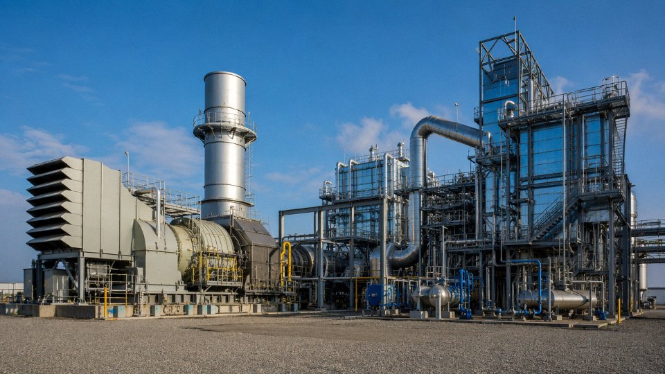
The equipment cost is only part of the picture. EPC delivery — civil works, structural steel, piping tie-ins, electrical, instrumentation, and commissioning — typically adds a 1.8–2.5× multiplier on equipment cost alone. Projects that underestimate this routinely blow their business case.
A Worked Example
Take a cement plant with a kiln exhaust carrying roughly 50 MW of recoverable heat. At a conservative gas equivalent value of USD 9/GJ and 8,000 operating hours per year, annual savings reach approximately USD 1.44 million. An EPC turnkey project — boiler, steam system, civil, commissioning — comes in around USD 5 million for a well-scoped job. Simple payback: about 3.5 years. That is before any tax incentives or carbon credits.
A well-designed industrial WHRB project can achieve an internal rate of return of 18–35% over a 25-year lifecycle at moderate fuel prices.True
IRR in this range is consistent with USD 8–12/GJ fuel pricing, 8,000 annual operating hours, and standard EPC costs of 1.8–2.5× equipment cost. Tighter pinch points, higher fuel prices, or carbon credit revenue push IRR toward the upper bound; low load factors or frequent forced outages compress it toward or below the lower bound.
An NPV analysis at an 8% discount rate over 25 years typically shows a strongly positive result for mid-scale projects — the long tail of fuel savings compounds significantly. Sensitivity matters here: a 20% drop in gas turbine load factor (common during grid demand troughs or process curtailments) reduces exhaust flow and temperature simultaneously, compressing annual savings by more than you would intuitively expect because both ṁ and ΔT fall together in the Q equation.
Carbon Credits and ESG Upside
Waste heat recovery directly displaces combustion and cuts CO2 emissions. At USD 25–80/tonne CO2 — depending on whether you are accessing voluntary carbon markets or a compliance scheme like the EU ETS or emerging Southeast Asian mechanisms — a mid-scale project recovering 30–50 MW can generate an additional USD 50,000–500,000 per year in carbon revenue. That figure is not guaranteed, and carbon prices are volatile, but for projects targeting ESG-linked financing or obligated emitters, it is real money worth modelling.
Government Incentives and Green Financing
Many target markets actively subsidize industrial energy efficiency. India’s PAT (Perform, Achieve and Trade) scheme, various Southeast Asian investment promotion boards, and several GCC industrial development programs offer accelerated depreciation, import duty exemptions on equipment, or low-interest green loans. WHRB projects consistently qualify given their measurable fuel savings. Securing this documentation during project development — not after the fact — is worth the administrative effort.
Risks That Erode Returns
The biggest ROI killers in practice are lower-than-designed gas turbine utilization, water treatment failures leading to tube leaks and forced outages (sometimes weeks of lost generation), and grid curtailment that leaves steam turbine capacity idle. A conservative design with appropriate margins on heat transfer surface area, robust feedwater chemistry controls, and a credible O&M contract are not optional extras — they are the difference between hitting your IRR target and explaining to the CFO why payback stretched to seven years.
FAQ
Q1: What is a waste heat recovery boiler and how does it work?
A waste heat recovery boiler is a thermal-energy system that captures heat from hot exhaust gases or industrial process streams and uses that energy to generate steam or hot water. Unlike a conventional fired boiler, which relies primarily on burning natural gas, oil, coal, or another fuel, a waste heat recovery boiler obtains most or all of its heat from energy that would otherwise be released through a stack, vent, cooling system, or exhaust duct.
The system is often called a waste heat boiler, exhaust gas boiler, or heat recovery steam generator. In gas turbine power and cogeneration applications, the term heat recovery steam generator, or HRSG, is especially common. An HRSG receives high-temperature exhaust from a gas turbine and transfers the exhaust heat to water flowing through banks of tubes. The water is heated, evaporated into steam, and sometimes superheated before being delivered to a steam turbine or industrial process.
A typical waste heat recovery boiler contains an exhaust-gas inlet, heat-transfer tubes, pressure components, steam drums or once-through circuits, economizers, evaporators, superheaters, feedwater systems, safety valves, controls, and an exhaust stack. Hot gas passes across the tube surfaces while water or steam flows inside the tubes. Thermal energy moves through the tube walls without allowing the exhaust gas and boiler water to mix.
The economizer is normally located in a lower-temperature section of the exhaust path and preheats incoming boiler feedwater. The evaporator converts heated water into saturated steam, while the superheater raises the steam temperature above saturation when higher-quality steam is required. Large HRSGs may include several pressure levels, such as high-pressure, intermediate-pressure, and low-pressure circuits, to recover energy efficiently across a wide exhaust-temperature range.
Waste heat recovery boilers can operate without supplementary fuel, in which case they are described as unfired units. Some systems include duct burners or supplementary firing equipment. These burners add fuel to the hot exhaust stream when additional steam or power output is required. Gas turbine exhaust usually contains sufficient remaining oxygen to support supplementary combustion.
In industrial plants, waste heat may come from furnaces, kilns, ovens, incinerators, reformers, smelters, engines, and chemical reactors. The boiler cools the exhaust while converting part of its thermal energy into useful steam. That steam can heat process equipment, drive mechanical equipment, generate electricity, supply a district heating network, or support cleaning and sterilization operations.
The effectiveness of a waste heat recovery boiler depends on exhaust temperature, flow rate, operating schedule, chemical composition, contamination levels, steam-pressure requirements, and the temperature at which the exhaust may safely leave the system. Corrosive compounds, dust, slag, and condensable substances may require specialized materials, cleaning equipment, or operating limits.
By recovering heat that would otherwise be discarded, the boiler can reduce the amount of additional fuel required to meet a facility’s steam and power demand. It may therefore improve overall plant efficiency, lower operating costs, and reduce emissions associated with supplemental fuel consumption. However, actual savings depend on whether the recovered steam or hot water can be used consistently.
Q2: How is a waste heat recovery boiler used with a gas turbine?
A waste heat recovery boiler is installed downstream of a gas turbine to capture thermal energy remaining in the turbine’s exhaust. Gas turbines generate electricity by compressing air, mixing it with fuel, burning the mixture, and expanding the hot combustion gases through turbine blades. Although part of the fuel’s energy is converted into shaft power, the exhaust leaving the turbine still contains substantial usable heat.
In a simple-cycle gas turbine plant, this exhaust is generally released after passing through the required exhaust and emissions systems. When a heat recovery steam generator is added, the turbine exhaust is directed through the HRSG instead. Water circulating through the HRSG absorbs the heat and becomes steam, allowing the plant to produce useful thermal energy or additional electricity.
In a combined-cycle power plant, the recovered steam is sent to a steam turbine connected to another electrical generator. The gas turbine produces the first portion of the plant’s electricity, while the steam turbine produces additional electricity from recovered exhaust heat. This arrangement extracts more useful energy from the same fuel input than a simple-cycle configuration.
A combined-cycle installation may use one gas turbine and one HRSG, or it may connect multiple gas turbines and HRSGs to a shared steam turbine. The HRSG can be designed with one, two, or three pressure levels. Multiple-pressure systems improve heat recovery by matching different water and steam circuits to different exhaust-temperature zones.
Gas turbine HRSGs commonly include economizer, evaporator, superheater, and sometimes reheater sections. Feedwater first enters the economizer, where lower-temperature exhaust heat raises its temperature. It then passes to the evaporator, where it becomes steam. The superheater increases the steam temperature before it enters the steam turbine or process-steam system. In a reheat cycle, partially expanded steam returns from the steam turbine to the HRSG for additional heating.
In combined heat and power applications, the recovered steam may be used directly instead of being used exclusively for electricity generation. Manufacturing plants, refineries, chemical facilities, paper mills, food-processing operations, hospitals, universities, and district energy plants can use gas turbine exhaust to produce process steam, space heating, hot water, or cooling through absorption equipment. Gas turbines are particularly suitable for CHP sites that have consistent demand for steam.
Some HRSGs use supplementary duct firing. Burners installed between the gas turbine and heat-transfer sections add fuel to increase exhaust temperature and steam output. Supplementary firing can help a plant meet peak steam demand, maintain process-steam production when turbine output changes, or increase steam turbine generation. However, it also increases fuel use and emissions compared with fully unfired heat recovery.
The HRSG must be designed for the gas turbine’s exhaust temperature, mass flow, oxygen content, pressure loss limits, operating cycles, and startup characteristics. Excessive exhaust backpressure can reduce gas turbine performance, while rapid temperature changes can create thermal stress in drums, headers, tubes, and piping.
A properly integrated gas turbine and waste heat recovery boiler can significantly improve total energy utilization. The value is greatest when both electricity and recovered thermal energy have reliable uses. The U.S. Department of Energy notes that capturing gas turbine waste heat for power, heating, or industrial purposes can substantially increase the efficiency of the overall energy system.
Q3: Where are waste heat recovery boilers used in industrial processes?
Waste heat recovery boilers are used in industrial facilities that produce continuous or regularly available streams of hot exhaust gas. Their purpose is to turn otherwise unused process heat into steam, hot water, mechanical power, or electricity. Suitable applications are found in industries with furnaces, kilns, reactors, incinerators, engines, turbines, and other high-temperature equipment.
In the iron and steel industry, waste heat boilers can recover energy from coke ovens, basic oxygen furnaces, electric arc furnaces, reheating furnaces, and other metallurgical operations. The recovered steam may be used elsewhere in the plant or supplied to a steam turbine. Because these exhaust streams may contain dust and corrosive compounds, the boiler may require erosion-resistant surfaces, online cleaning systems, and specialized gas-conditioning equipment.
Nonferrous metal operations, including copper, aluminum, nickel, and zinc production, also generate high-temperature process gases. Waste heat boilers can cool these gases before downstream treatment while producing steam. In some applications, rapid gas cooling is also an important part of process control or environmental management.
Cement and lime plants release substantial heat through kiln exhaust and clinker-cooling systems. Heat recovery equipment can capture part of this energy for steam generation or electricity production. The technical design must account for dust loading, variable plant output, and the temperature limits of downstream process equipment. The U.S. Environmental Protection Agency identifies cement kilns, furnaces, ovens, gas turbines, and other industrial equipment as potential medium- or high-temperature waste heat sources.
In petroleum refineries and petrochemical plants, waste heat boilers may be installed downstream of process heaters, catalytic units, sulfur-recovery equipment, hydrogen plants, cracking processes, and high-temperature reactors. Steam produced from recovered heat may support distillation, stripping, tracing, cleaning, pumping, or electricity generation.
Chemical and fertilizer facilities often use waste heat boilers after exothermic reactions or synthesis processes. Ammonia, sulfuric acid, nitric acid, hydrogen, and other chemical-production systems can release enough thermal energy to generate significant quantities of steam. In these installations, the waste heat boiler may be an integral part of the chemical process rather than an optional energy-saving accessory.
Glass plants can recover heat from melting-furnace exhaust, while ceramic and brick facilities may recover kiln heat. Pulp and paper mills can use recovery systems around combustion equipment, dryers, and process exhaust. Food and beverage plants may recover heat from ovens, dryers, thermal oxidizers, engines, and cogeneration systems, although lower temperatures can limit the steam pressure that can be economically produced.
Waste heat boilers are also used with reciprocating engines and industrial gas turbines. Engine or turbine exhaust is directed through the boiler to produce steam or hot water for the same facility. This arrangement is common in combined heat and power plants where electricity and thermal energy are required simultaneously.
Incineration and thermal oxidation systems represent another major application. A waste heat boiler can cool combustion gases and generate steam before the gases enter particulate-control, scrubbing, or other treatment equipment. Boiler materials and operating temperatures must be selected carefully when the exhaust contains chlorine, sulfur, metals, ash, or other corrosive contaminants.
The best industrial applications generally have a stable heat source and a dependable demand for the recovered energy. Facilities must evaluate exhaust availability, steam requirements, heat quality, fouling risks, maintenance access, operating pressure, corrosion, and economic payback. Waste heat recovery is most effective when it is integrated into the overall process rather than treated as an isolated piece of equipment.
Q4: What is the difference between a waste heat boiler and an HRSG?
The terms waste heat boiler and heat recovery steam generator are closely related and are sometimes used interchangeably. Both describe equipment that captures thermal energy from an exhaust or process-gas stream and uses it to produce steam. However, their usage, design context, and typical applications can differ.
A waste heat boiler is the broader term. It can refer to almost any boiler that recovers heat from an industrial process instead of obtaining all of its heat from direct fuel combustion. Waste heat boilers may be installed after metallurgical furnaces, chemical reactors, incinerators, kilns, engines, thermal oxidizers, smelters, or petroleum-processing equipment.
An HRSG is a specific type of waste heat recovery boiler most commonly associated with gas turbines. It captures heat from gas turbine exhaust and generates steam for a steam turbine, industrial process, district heating system, or combined heat and power application. The U.S. Department of Energy describes an HRSG as a common heat-recovery unit used in gas turbine CHP systems.
HRSGs are generally engineered around predictable gas turbine exhaust conditions. The exhaust is relatively clean compared with many industrial furnace or kiln streams, although its temperature and mass flow change with turbine load and ambient conditions. A large combined-cycle HRSG may contain high-, intermediate-, and low-pressure steam circuits, along with economizers, evaporators, superheaters, reheaters, drums, bypass systems, and emissions-control equipment.
Industrial waste heat boilers may encounter more difficult gas compositions. Exhaust from smelting, cement, chemical processing, or waste treatment can contain ash, sticky particles, corrosive vapors, erosive solids, or process chemicals. These units may therefore use wider tube spacing, specialized alloys, refractory linings, soot blowers, mechanical cleaning systems, or unusual gas-flow arrangements.
Another distinction involves plant purpose. In a combined-cycle power plant, the HRSG is a major component of the power-generation cycle. Its steam conditions, pressure levels, startup performance, and integration with the steam turbine directly affect electrical output and plant efficiency. In an industrial facility, a waste heat boiler may primarily provide process steam, cool a reaction stream, protect downstream equipment, or maintain a required process temperature.
Both HRSGs and industrial waste heat boilers may be unfired or supplementary fired. An unfired unit relies entirely on incoming exhaust heat. A supplementary fired HRSG uses duct burners to increase gas temperature and steam output. Some industrial waste heat boilers also include auxiliary burners to stabilize steam production or maintain operating conditions when process heat is unavailable.
The physical configuration can also vary. HRSGs may be horizontal or vertical, natural-circulation, assisted-circulation, or once-through designs. Industrial waste heat boilers may use firetube, watertube, waterwall, shell-and-tube, or highly customized process-specific arrangements.
Despite these differences, the operating principle is the same: hot gas transfers energy through metal surfaces to water or steam without directly mixing the two fluids. The selected term often depends more on industry practice than on a strict technical boundary.
For SEO and procurement purposes, an HRSG can accurately be described as a gas turbine waste heat recovery boiler. However, not every waste heat boiler is an HRSG. Equipment recovering heat from a cement kiln, chemical reactor, or smelting furnace would usually be called a waste heat boiler rather than a gas turbine HRSG.
Q5: What are the benefits and limitations of waste heat recovery boilers?
The primary benefit of a waste heat recovery boiler is improved energy efficiency. It converts exhaust energy that would otherwise be released into the environment into useful steam or hot water. The recovered energy can reduce the amount of fuel consumed by conventional boilers, increase electricity generation, or supply thermal energy for industrial processes.
In a combined-cycle power plant, an HRSG allows gas turbine exhaust to generate steam for a steam turbine. This produces additional electricity from heat remaining after the gas turbine has already generated power. In a combined heat and power system, the recovered steam can serve industrial or building loads, improving total fuel utilization when the thermal output is consistently required.
Lower fuel consumption can also reduce operating costs. A facility may purchase less natural gas or other boiler fuel while producing the same amount of steam. The financial benefit depends on fuel prices, operating hours, maintenance costs, steam demand, system pressure, and the amount of recoverable heat.
Waste heat recovery may reduce carbon dioxide and combustion-related air emissions by displacing fuel that would otherwise be burned in a separate boiler. It can also reduce the temperature of process exhaust before downstream treatment. In some chemical and metallurgical applications, controlled cooling of process gases is necessary for production quality or emissions-control performance.
Another benefit is energy resilience. Facilities with on-site gas turbines, engines, or high-temperature processes can produce part of their own steam or electricity. This may reduce dependence on purchased energy and improve operational flexibility, although the recovery boiler remains dependent on the availability of its upstream heat source.
Waste heat recovery boilers also have important limitations. The first is that they do not create energy independently. Steam production changes when the gas turbine or industrial process changes load, shuts down, or produces cooler exhaust. A facility requiring uninterrupted steam may need an auxiliary fired boiler, supplementary burner, thermal storage system, or connection to another steam source.
Capital cost can be substantial. The project may require the boiler, structural steel, ductwork, feedwater equipment, steam piping, controls, emissions systems, foundations, electrical work, water treatment, and modifications to existing process equipment. Installation can be especially challenging in operating industrial plants with limited space or short outage windows.
Fouling, erosion, and corrosion are major concerns in industrial applications. Dust and sticky particles can accumulate on heat-transfer surfaces and reduce performance. Corrosive chemicals may damage tubes, headers, and ductwork. Low exhaust temperatures can also cause acidic vapors or water to condense, creating corrosion risks.
Gas-side pressure drop must be carefully controlled. Adding a recovery boiler creates resistance in the exhaust path. Excessive backpressure can reduce gas turbine or engine output and may disrupt the upstream industrial process. Engineers must balance additional heat-transfer surface against acceptable pressure loss.
Water quality is another critical requirement. Deposits inside boiler tubes can restrict heat transfer and cause overheating, while oxygen and improper chemical conditions can lead to corrosion. High-pressure HRSGs require particularly strict feedwater and steam-quality control.
Operational cycling may create thermal fatigue. Frequent starts, stops, and rapid load changes cause metal components to expand and contract. Drums, headers, superheaters, tube connections, and thick-walled components must be designed and operated to limit damaging thermal stress.
A waste heat recovery boiler is therefore most attractive when the heat source is reliable, the exhaust temperature is adequate, and the recovered steam has a consistent use. A detailed feasibility study should examine heat availability, steam demand, process integration, contamination, pressure drop, maintenance, environmental requirements, and expected economic return.
References
How Gas Turbine Power Plants Work
https://www.energy.gov/hgeo/how-gas-turbine-power-plants-work
Source: U.S. Department of EnergyWaste Heat Recovery Basics
https://www.energy.gov/cmei/ito/waste-heat-recovery-basics
Source: U.S. Department of EnergyGuide to Combined Heat and Power Systems for Boiler Owners and Operators
https://www.energy.gov/sites/prod/files/2014/05/f15/guide_chp_boiler.pdf
Source: U.S. Department of EnergyWhat Is Combined Heat and Power?
https://www.epa.gov/chp/what-chp
Source: U.S. Environmental Protection AgencyCombined Heat and Power Technologies
https://www.epa.gov/chp/chp-technologies
Source: U.S. Environmental Protection AgencyWaste Heat to Power Systems
https://www.epa.gov/sites/default/files/2015-07/documents/waste_heat_to_power_systems.pdf
Source: U.S. Environmental Protection AgencyProcess Heating Systems
https://www.energy.gov/cmei/ito/process-heating-systems
Source: U.S. Department of EnergySteam Systems
https://www.energy.gov/cmei/ito/steam-systems
Source: U.S. Department of EnergyCombined Heat and Power Technology Fact Sheet: Gas Turbines
https://betterbuildingssolutioncenter.energy.gov/resources/combined-heat-and-power-technology-fact-sheet-gas-turbines
Source: U.S. Department of Energy Better Buildings Solution CenterIntroduction to the Boiler House
https://www.spiraxsarco.com/learn-about-steam/the-boiler-house/introduction
Source: Spirax Sarco