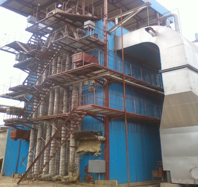
Waste heat recovery boilers (WHRBs) use thermal energy from industrial exhaust gases to generate steam or hot water. Unlike conventional fired boilers, their operating conditions are strongly influenced by upstream processes, exhaust gas composition, temperature fluctuations, and heat-transfer surface arrangements.
These conditions can contribute to tube erosion, corrosion, wall thinning, fatigue cracking, and deterioration around welded connections. However, the location and severity of damage depend on the boiler’s design, materials, water chemistry, and operating history.
Effective waste heat recovery boiler NDT inspection requires more than selecting an ultrasonic or surface-testing method. Inspectors must first identify potential damage mechanisms, determine suitable examination locations, establish inspection coverage, and evaluate the findings against applicable requirements.
This guide explains how to inspect WHRB tubes, heat-transfer surfaces, steam drums, headers, and welded connections using nondestructive testing (NDT), with emphasis on practical inspection planning, method selection, and interpretation of results.
1. What Should Be Inspected in a Waste Heat Recovery Boiler?
Inspection priorities should be established from the equipment configuration, operating conditions, previous inspection findings, and potential deterioration mechanisms.
Critical Components and Potential Damage Locations
Depending on the WHRB design, the examination may cover economizer tubes, evaporator tubes, superheater tubes, steam drums, headers, and welded connections.
Not every installation contains all these components. Inspection planning must therefore follow the actual pressure-part arrangement rather than a generic boiler checklist.
Table 1. Critical WHRB Components and Potential Damage Mechanisms
| Component | Potential Damage | Priority Inspection Areas |
|---|---|---|
| Economizer tubes | Corrosion, erosion, localized wall thinning | Susceptible inlet sections, exposed tubes, bends |
| Evaporator tubes | Corrosion, wall loss, fatigue-related damage | Tube bends, connections, areas with abnormal operating history |
| Superheater tubes | Overheating, thermal fatigue, high-temperature degradation | High-temperature sections, bends, welds |
| Steam drums | Corrosion, cracking, localized thinning | Shell surfaces, nozzles, welds |
| Headers and manifolds | Thermal-fatigue cracking, localized corrosion | Tube connections, welds, geometric transitions |
| Finned tube banks | Corrosion or wall loss with restricted examination access | Susceptible tube sections beneath or between fins |
The table identifies possible inspection targets, not defects that necessarily occur in every waste heat boiler.
How Waste Heat Source Conditions Affect Inspection Priorities
The upstream industrial process can significantly influence the examination strategy.
For example:
- Dust-laden exhaust gases: Abrasive particles may cause localized erosion on exposed tubes, especially where gas flow changes direction or concentrates.
- Corrosive gas constituents: Depending on surface temperature and deposit chemistry, certain tube sections may experience localized corrosion.
- Frequent temperature cycling: Repeated thermal expansion and contraction may contribute to fatigue damage around constrained connections and welded joints.
- Water-side operating conditions: Inadequate water chemistry, deposits, or unfavorable flow conditions can contribute to corrosion and wall thinning.
These mechanisms require different inspection priorities.
The Electric Power Research Institute (EPRI) provides a damage-mechanism-based approach in its Guidelines for the Nondestructive Examination of Heat Recovery Steam Generators.
Although this reference is particularly relevant to HRSGs, its principles should be applied to other industrial WHRB configurations only where the design and damage mechanisms are comparable.
Industrial Application Context
Industrial WHRB configurations also vary according to the requirements of individual projects.
For example, Taishan Group’s published project references include the supply of one high-pressure drum and one low-pressure drum for a 70-ton waste heat boiler at Brazil’s Parnaíba Complex, as well as a steam drum for an 18 t/h waste heat boiler associated with POSCO Steeleon in South Korea.
These examples illustrate different industrial applications involving WHRB pressure parts. They are equipment-supply references, not documented NDT inspection case studies.
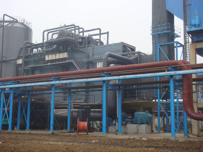
2. Which NDT Methods Are Suitable for WHRB Components?
The examination method should correspond to the suspected damage mechanism, component material, geometry, defect orientation, and available access.
No single NDT technique is suitable for every WHRB component or deterioration mechanism.
Common NDT Techniques
The following methods may be considered:
- Visual Testing (VT): Identifies visible corrosion, surface deterioration, deformation, and other accessible indications.
- Ultrasonic Testing (UT): Measures remaining wall thickness and, with suitable techniques, detects selected internal discontinuities.
- Phased Array Ultrasonic Testing (PAUT): Provides controlled ultrasonic scanning for suitable welds and other examination geometries.
- Magnetic Particle Testing (MT): Detects surface and near-surface discontinuities in ferromagnetic materials.
- Liquid Penetrant Testing (PT): Detects surface-breaking discontinuities in suitable nonporous materials.
- Radiographic Testing (RT): Examines selected internal discontinuities where geometry, access, and radiographic arrangements permit.
- Electromagnetic Testing (ET): Includes specialized techniques that may be suitable for certain tubing configurations.
The American Society for Nondestructive Testing (ASNT) provides further information about these examination methods.
NDT Method Selection Matrix
Table 2. NDT Methods for Common WHRB Inspection Conditions
| Suspected Condition | Candidate NDT Method | Key Consideration |
|---|---|---|
| Accessible tube wall thinning | UT thickness measurement | Surface access and measurement reliability |
| Surface-breaking cracks | MT or PT | Material compatibility and surface preparation |
| Selected weld discontinuities | UT, PAUT, or RT | Weld geometry, defect orientation, procedure applicability |
| Localized corrosion or erosion | VT and targeted UT | Examination extent and accessibility |
| Restricted finned tube degradation | Qualified specialized electromagnetic methods | Tube geometry, calibration, and technique capability |
Method selection must be confirmed against the relevant examination procedure.
For example, MT is inappropriate for nonferromagnetic materials, while conventional contact UT may not provide sufficient coverage in tightly packed finned-tube arrangements.
For complex welded connections, probe access and defect orientation must be considered before selecting UT or PAUT.
3. How to Prepare a WHRB for NDT Inspection
Reliable examination depends on appropriate equipment preparation and clearly defined inspection coverage.
Safety Isolation and Inspection Readiness
Before examination, qualified personnel should verify that the relevant boiler components are safely prepared.
Depending on the work scope, preparation may include:
- Shutting down and isolating the relevant systems.
- Controlling stored energy and confirming depressurization.
- Draining and cooling the components as required.
- Establishing appropriate confined-space entry arrangements where necessary.
- Confirming inspection procedures, equipment calibration, personnel qualifications, and site authorizations.
The specific requirements depend on the equipment configuration and applicable safety regulations.
Surface Preparation and Inspection Access
Surface condition directly affects examination effectiveness.
Deposits, corrosion products, coatings, and uneven surfaces may interfere with ultrasonic measurements or surface examination techniques.
Inspectors should identify the locations requiring preparation and determine whether adequate access exists.
For conventional contact UT, suitable probe positioning and acoustic coupling are necessary. Surface-testing techniques have their own cleaning and preparation requirements.
Inaccessible regions should be identified before examination begins and documented in the final report.
For broader outage planning and routine equipment-care considerations, see Best Practices for Routine Waste Heat Recovery Boiler Maintenance.
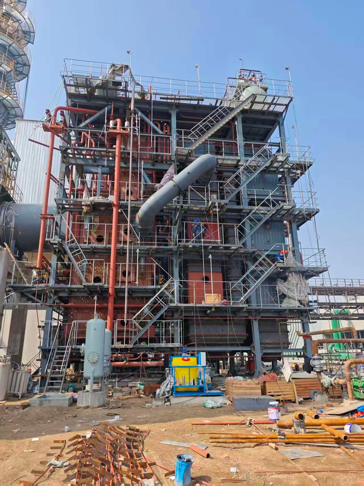
4. How to Inspect WHRB Tubes and Heat-Transfer Surfaces Using NDT
WHRB tube inspection should follow a damage-mechanism-based examination sequence.
Rather than applying identical measurements across every tube, inspectors should establish initial examination locations, assess the results, and modify coverage when evidence indicates localized deterioration.
Step 1 — Identify Tube Circuits and Suspected Damage Areas
Review engineering drawings, tube layouts, operating records, material information, and previous inspection findings.
The examination plan should identify the relevant tube circuits and likely damage locations.
For example, where gas-side erosion is suspected, initial examination locations may include:
- Tube sections directly exposed to particulate-laden gas.
- Locations where gas flow changes direction or concentrates.
- Tubes adjacent to areas with previously reported erosion.
- Accessible bends or transitions showing signs of deterioration.
Where water-side corrosion is suspected, inspection locations should instead be selected according to the relevant water chemistry, circulation conditions, deposits, and examination history.
The objective is to connect inspection coverage with credible damage mechanisms rather than assume that all tube surfaces deteriorate uniformly.
Step 2 — Examine Tube Walls for Thinning and Localized Damage
Visual examination can identify accessible surface conditions such as corrosion products, erosion marks, deformation, and other visible abnormalities.
Where thickness reduction is suspected, suitable ultrasonic measurements can help quantify remaining wall thickness.
An effective examination approach includes:
- Establishing identifiable measurement locations using tube numbering or drawings.
- Preparing the selected surfaces.
- Performing measurements using an appropriate calibrated technique.
- Recording results against their exact locations.
- Reviewing measurements for unusual values or localized variations.
If a measurement suggests significant localized thinning, inspectors should not rely on that reading alone.
The finding should first be checked for possible measurement error, inadequate coupling, unsuitable surface conditions, or other technical limitations.
If the indication remains credible, additional measurements can be taken around the affected area to better characterize the extent and distribution of wall loss.
The required examination expansion depends on the suspected deterioration mechanism and approved inspection plan.
Step 3 — Adapt Inspection Coverage to the Operating Conditions
Three common WHRB operating scenarios illustrate why inspection strategies should differ.
Scenario A: Dust-Laden Industrial Exhaust Gas
Where abrasive gas-side erosion is suspected, inspection should focus on surfaces exposed to concentrated particulate impact.
Initial visual and thickness examinations may identify localized damage rather than uniform wall loss.
If affected tubes are found, the inspection scope may need to expand to adjacent tubes exposed to similar gas-flow conditions.
Scenario B: Repeated Thermal Cycling
Where frequent startup, shutdown, or temperature changes create fatigue concerns, the inspection strategy may prioritize tube bends, connections, and constrained welded joints.
Suitable surface or volumetric examination methods should be selected according to the expected crack location and orientation.
Scenario C: Restricted Finned-Tube Banks
Where fins or narrow tube spacing prevent adequate conventional UT access, the examination plan should evaluate suitable specialized techniques.
Screening results may require additional targeted measurements to confirm the extent of suspected wall loss.
These examples are general engineering inspection scenarios, not reports of specific defects found at Taishan Group installations.
Step 4 — Inspect Tube Bends and Potential Crack Locations
Tube bends and welded connections may require additional examination where operating history suggests cyclic stresses, vibration, or abnormal thermal loading.
The inspection process should identify:
- The expected crack location.
- Whether a surface or internal discontinuity is suspected.
- Component material and surface accessibility.
- Suitable examination methods and their coverage limitations.
For compatible ferromagnetic components, MT may be appropriate for selected surface and near-surface indications.
PT can be considered for suitable materials where surface-breaking discontinuities are suspected.
Ultrasonic techniques may be selected where component geometry and qualified procedures permit effective examination.
Because curvature and geometric transitions can complicate inspection, questionable findings should be evaluated before being treated as confirmed defects.
Step 5 — Inspect Finned Tubes and Restricted Tube Banks
Finned tubes require particular attention because their geometry can limit direct access to the pressure-retaining tube wall.
Conventional contact UT may be suitable at accessible locations but insufficient for examining the entire finned region.
Specialized electromagnetic techniques may offer additional examination possibilities.
For example, Intertek’s Heat Recovery Steam Generator Inspection information describes a pulsed eddy current system designed to assess wall thinning in certain finned-tube configurations.
However, successful application depends on material properties, tube dimensions, fin configuration, calibration arrangements, and the technique’s demonstrated capability.
A screening indication should not automatically be interpreted as a direct measurement of the minimum remaining wall thickness.
Where results indicate possible degradation, supplementary measurements or further engineering evaluation may be required.
The inspection report should clearly distinguish examined areas, screened areas, and locations where reliable examination could not be achieved.
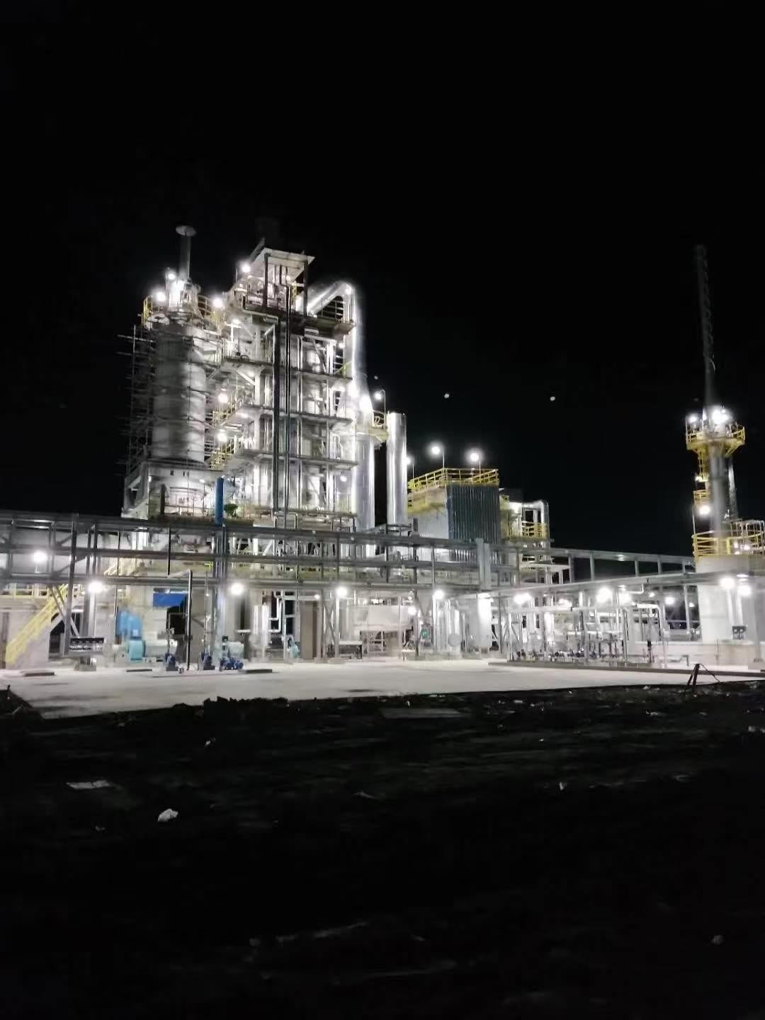
5. How to Inspect Steam Drums, Headers, and Welded Connections
Steam drums, headers, and welded connections require component-specific inspection plans because their geometry and potential damage mechanisms differ from those of heat-transfer tube banks.
Steam Drum Inspection
For WHRBs equipped with steam drums, examination planning may cover the shell, accessible internal surfaces, welds, nozzles, and selected attachment locations.
Visual examination can identify corrosion, surface irregularities, deposits, and visible deterioration.
Where wall thinning is suspected, appropriately located UT measurements can help characterize the affected region.
If fatigue or other cracking mechanisms are credible, the examiner should determine whether surface examination, volumetric examination, or a combination is appropriate.
The method should account for material properties, potential crack orientation, and access to the examination surface.
For example, MT may be appropriate for selected ferromagnetic surfaces, while UT or PAUT may be considered for suitable weld configurations.
The examination scope should be determined from the actual drum condition and governing requirements rather than assuming that every weld requires the same examination technique.
Header and Manifold Inspection
Headers and manifolds are particularly important where thermal cycling or other operating conditions may impose repeated stresses on welded connections.
Potential examination locations include:
- Header-to-tube connections.
- Pressure-boundary welds.
- Nozzles and geometric transitions.
- Areas with recorded thermal transients.
- Locations where localized wall loss or corrosion is suspected.
Inspection planning should distinguish between different damage mechanisms.
For suspected surface cracking, an appropriate surface-testing method may be suitable.
For selected internal weld discontinuities, ultrasonic examination may be appropriate when the geometry, material, and procedure support adequate coverage.
If wall thinning is suspected, targeted thickness measurements may be required.
In components exposed to sufficiently high temperatures and stresses over extended periods, creep-related deterioration may also warrant specialized engineering assessment.
However, conventional wall-thickness measurements alone cannot establish the absence of all creep damage.
Tube-to-Header Weld Inspection
Tube-to-header connections are often geometrically complex and may be difficult to examine using conventional scanning arrangements.
Where operating conditions indicate possible fatigue damage, inspection planning should consider weld toes, heat-affected zones, and accessible adjoining material.
A practical approach involves:
- Identifying the specific connection and expected damage location.
- Determining whether surface-breaking or internal cracking is suspected.
- Evaluating the suitability of MT, PT, UT, or PAUT for the actual joint geometry.
- Establishing examination coverage and recording limitations.
- Confirming questionable indications using suitable supplementary examination where necessary.
An examination technique should not be considered adequate simply because it is commonly used for pressure-part welds.
For complex tube-to-header joints, the inspection procedure must demonstrate that the intended area can be examined with sufficient reliability.
EPRI’s HRSG nondestructive examination guidelines provide useful background on the relationship between damage mechanisms, examination access, and technique selection for such components.
6. How Should WHRB NDT Findings Be Evaluated and Reported?
NDT findings should provide traceable information that can support engineering assessment and future inspection planning.
Verify and Characterize Inspection Findings
Before drawing conclusions from an abnormal reading or indication, the examiner should assess whether it may have been influenced by examination conditions.
For example, an unexpected UT thickness reading should be checked for calibration issues, surface condition, coupling problems, or measurement-location differences.
Where the indication remains credible, additional examination may be needed to establish its location and extent.
For localized wall loss, this may involve extending measurements around the affected position.
For a suspected crack, it may require a suitable complementary technique or a revised examination arrangement.
The objective is to characterize the condition reliably before determining the appropriate engineering response.
Evaluate Findings Against Applicable Requirements
The significance of an examination result depends on more than the measured indication.
Assessment may require consideration of:
- Component design and material specification.
- Actual operating pressure and temperature.
- Relevant deterioration mechanisms.
- Examination coverage and uncertainty.
- Previous inspection findings.
- Applicable acceptance and engineering assessment requirements.
A single minimum-wall-thickness percentage should not be treated as a universal rejection criterion for all WHRB pressure parts.
Similarly, the absence of reportable indications does not establish that every possible defect or deterioration mechanism has been excluded.
Where findings cannot be demonstrated to satisfy applicable requirements, qualified personnel should determine the necessary further evaluation or disposition before continued service is authorized.
If abnormal operating symptoms also require investigation, the separate guide on Troubleshooting Common Waste Heat Recovery Boiler Issues addresses broader diagnostic considerations.
What Should an NDT Inspection Report Include?
A useful WHRB NDT report should clearly identify:
- Examined components and exact locations.
- Inspection dates, methods, and procedure references.
- Personnel and equipment information required for traceability.
- Recorded thickness readings or other examination indications.
- Actual inspection coverage and inaccessible areas.
- Comparison with historical findings, where available.
- Results requiring confirmation or further engineering assessment.
For equipment owners and EPC contractors, this information helps distinguish documented examination results from assumptions about component condition.
A well-structured report also provides a reference for future examinations and helps prevent incomplete inspection coverage from being overlooked.
7. Which Standards and Technical Limitations Apply to WHRB NDT?
Applicable Codes and Inspection Requirements
The ASME Boiler and Pressure Vessel Code, Section V — Nondestructive Examination provides requirements and methods for NDT when invoked by applicable codes or referencing documents.
However, Section V does not independently establish universal in-service acceptance criteria for every WHRB defect.
The governing construction code, in-service inspection requirements, local regulations, project specifications, and applicable engineering assessment procedures must also be considered.
The applicable code editions should be established from the governing documents rather than automatically assuming that the latest publication applies to every installation.
Understanding NDT Limitations
NDT reliability depends on the examination method, component geometry, material condition, accessibility, personnel competence, and procedure suitability.
Surface-testing methods cannot identify every internal defect, while volumetric techniques may have limitations related to defect orientation or examination access.
Specialized tube-screening techniques may also require supplementary confirmation.
Inspection results should therefore be interpreted in the context of the actual examination capability and documented coverage.
Conclusion
Effective waste heat recovery boiler NDT inspection begins with understanding the equipment’s configuration, operating history, and potential damage mechanisms.
Tube banks, heat-transfer surfaces, steam drums, headers, and welded connections may require different examination techniques and inspection priorities.
By selecting suitable NDT methods, confirming examination coverage, investigating questionable findings, and documenting results accurately, engineering teams can develop a more reliable understanding of WHRB pressure-part condition.
For industrial projects involving different waste heat sources and boiler configurations, suitable pressure-part design and inspection planning should be considered together.
Explore Taishan Group’s Waste Heat Recovery Boiler products and applications for additional information on industrial waste heat recovery equipment.
Frequently Asked Questions
1. What is the best NDT method for measuring waste heat boiler tube wall thickness?
Ultrasonic thickness measurement is commonly used for accessible WHRB tubes because it provides quantitative thickness information. However, examination reliability depends on surface preparation, coupling, calibration, and component geometry. Closely spaced or finned tube arrangements may require specialized methods or alternative access arrangements.
2. Can NDT detect cracks in WHRB headers and tube-to-header welds?
Yes. MT and PT can identify suitable surface-breaking discontinuities, while UT or PAUT may detect selected internal or subsurface defects. The appropriate technique depends on the material, joint geometry, suspected crack orientation, and qualified examination procedure.
3. How are finned tubes inspected when conventional ultrasonic testing is difficult?
Specialized electromagnetic techniques, including suitable pulsed eddy current methods, may be considered for certain finned-tube arrangements. Their capability depends on the tube material, geometry, calibration, and specific examination objective. Suspicious results may require supplementary measurements or further engineering evaluation.
4. How often should waste heat recovery boiler tubes and drums undergo NDT inspection?
There is no universal NDT inspection interval appropriate for every WHRB. The examination schedule should be established according to applicable regulations, governing inspection requirements, equipment design, operating conditions, suspected damage mechanisms, and previous findings. Qualified personnel should determine the appropriate examination scope and frequency.