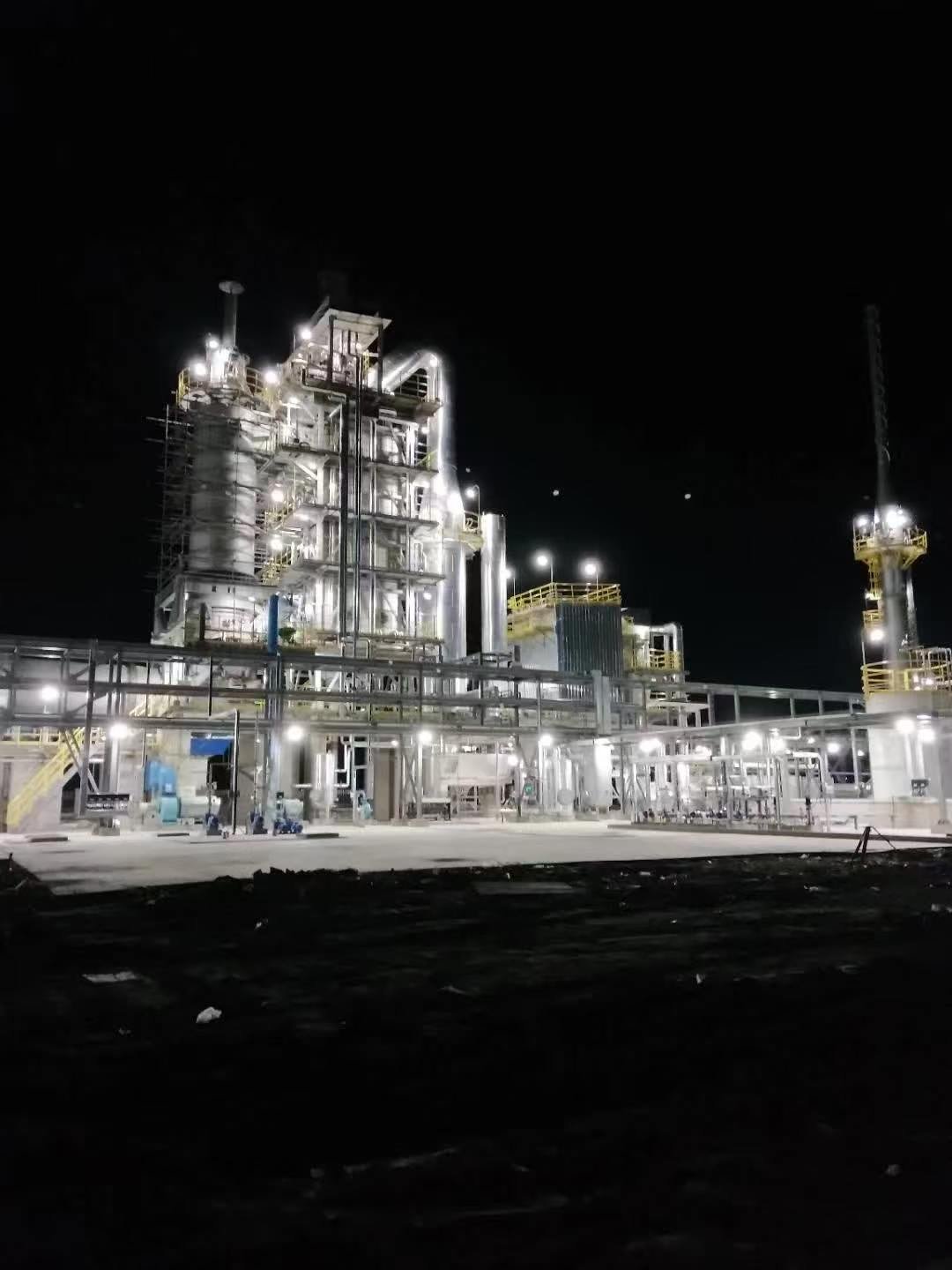
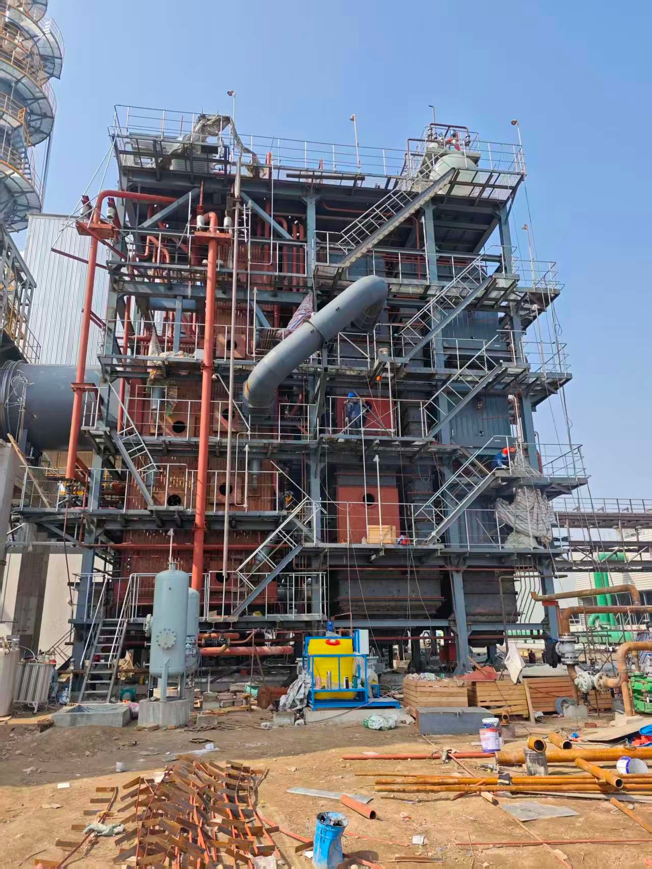
The main components of a power plant boiler typically include the furnace, water walls or evaporator, steam drum or separator where applicable, downcomers and headers, superheater, reheater where required, economizer, air preheater, burners or fuel-introduction system, and draft equipment.
These components do not operate independently. Together, they form interconnected combustion, water-steam, air, and flue-gas paths that convert fuel energy into high-temperature, high-pressure steam for power generation.
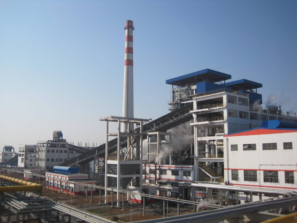
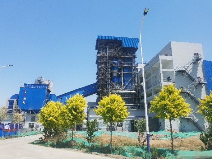
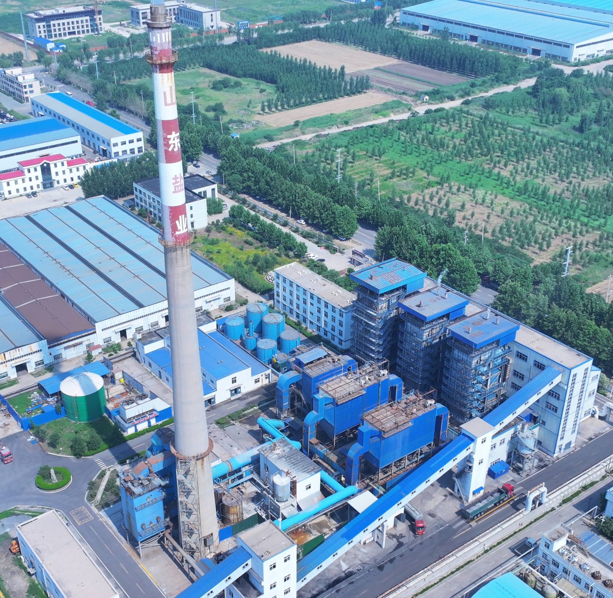
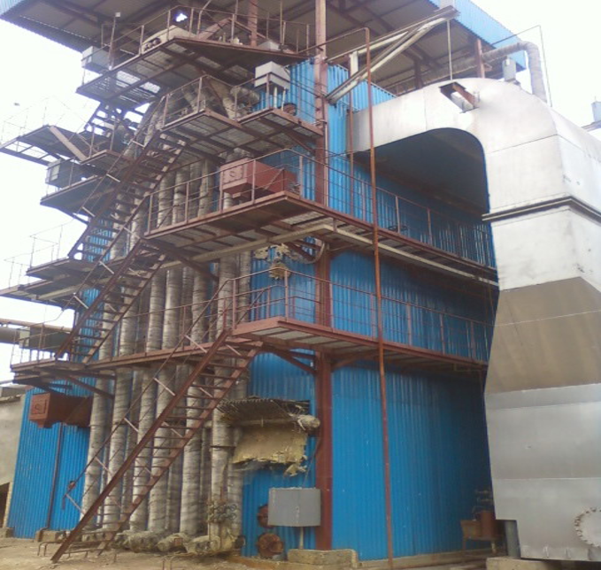
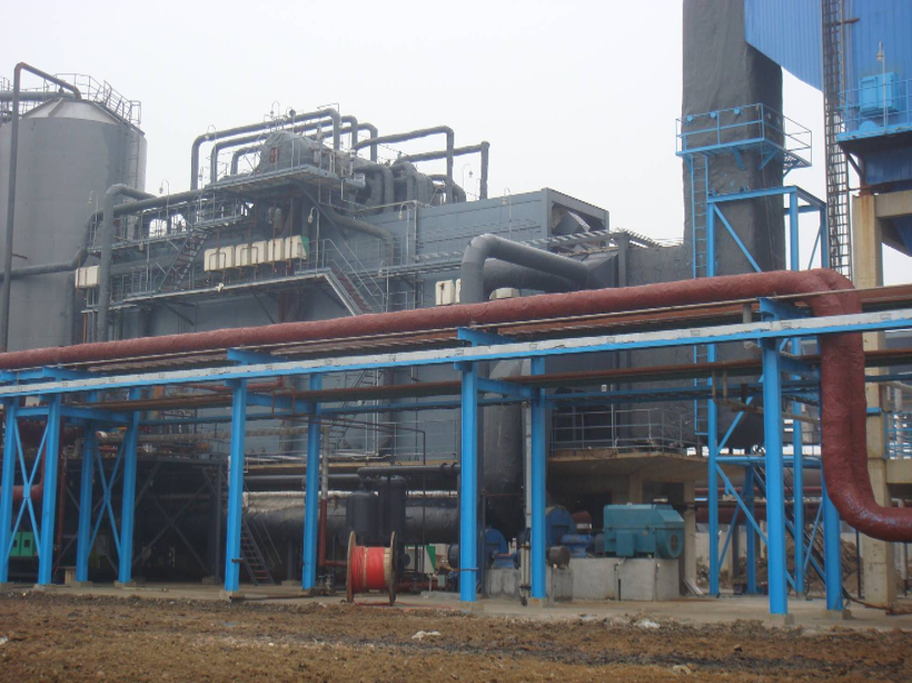
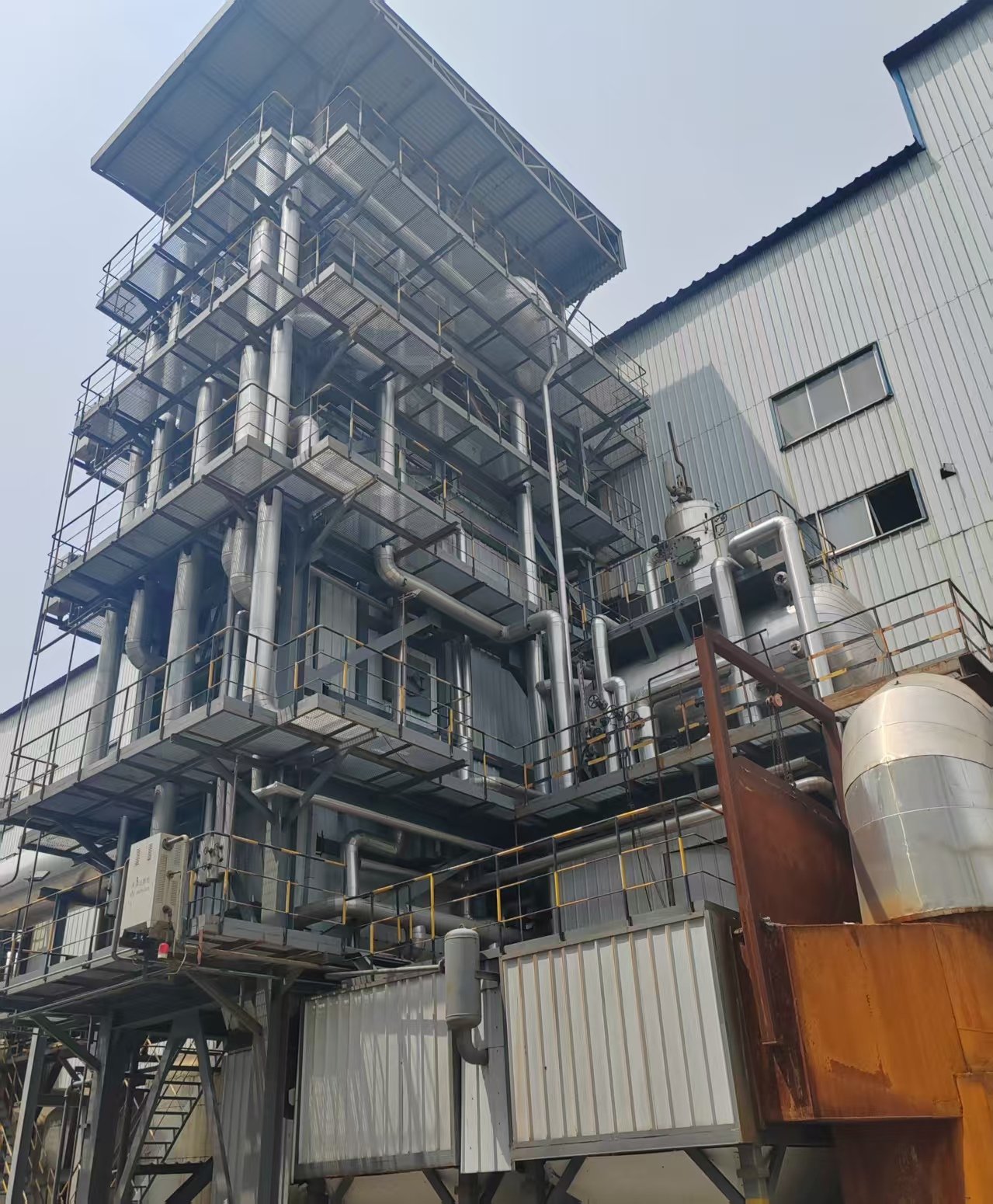
Power Plant Boiler Project Example: This 50 MW coal-fired power plant project illustrates how the boiler pressure parts, steel structure, draft system, auxiliaries, and other equipment are integrated into a complete boiler island.
The exact arrangement depends on the boiler design. A drum-type subcritical boiler, an once-through supercritical boiler, a pulverized-coal boiler, and a circulating fluidized bed (CFB) boiler do not necessarily contain the same component configuration.
Provides the combustion and primary heat-release zone
Fuel, combustion air, flue gas
Water walls / evaporator
Absorb furnace heat and generate steam or a steam-water mixture
Water / steam
Steam drum
Separates steam from water and supports circulation in drum-type boilers
Water / steam
Downcomers and headers
Distribute and circulate water through the evaporative circuit
Water / steam
Superheater
Raises main steam temperature above saturation
Steam
Reheater
Reheats steam after expansion through the high-pressure turbine
Steam
Economizer
Uses flue-gas heat to preheat boiler feedwater
Feedwater / flue gas
Air preheater
Uses flue-gas heat to preheat combustion air
Air / flue gas
Burners / fuel-introduction system
Introduces fuel into the combustion zone
Fuel / air
Draft system
Supplies combustion air and moves flue gas through the boiler
Air / flue gas
Fans, feedwater pumps, sootblowers, controls, safety devices, ash-handling equipment, and environmental systems are also essential to a complete boiler installation. However, they are usually better distinguished from the boiler’s primary pressure parts and heat-transfer surfaces.
What Counts as a Power Plant Boiler Component?
The term boiler component can describe different scopes depending on the project.
In a relatively narrow engineering sense, the boiler proper consists primarily of the furnace enclosure, pressure parts, steam-water circulation components, and heating surfaces involved directly in steam generation and steam-temperature control.
These include components such as:
water walls;
steam drums or separators;
headers and downcomers;
superheaters;
reheaters; and
economizers.
A wider boiler island may additionally include fuel-handling equipment, burners, primary-air and forced-draft fans, induced-draft fans, sootblowers, ash-handling systems, boiler controls, pumps, and associated flue-gas treatment equipment.
The distinction is important in EPC and procurement projects because a pressure-part supply package and a complete boiler-island package can have very different equipment boundaries.
For power boilers designed and constructed to ASME requirements, ASME Boiler and Pressure Vessel Code Section I provides construction rules applicable to power boilers.
1. Furnace and Combustion Zone
The furnace is the main heat-release zone of a fired power boiler.
Fuel and combustion air enter the furnace, combustion takes place, and the resulting thermal energy is transferred to the surrounding heating surfaces.
In many large water-tube boilers, the furnace enclosure itself is formed largely by water-cooled membrane walls. Closely spaced tubes connected by metal fins create a gas-tight enclosure while allowing the tubes to absorb intense radiant heat.
The furnace therefore serves two closely related functions:
providing sufficient space and conditions for combustion; and
transferring radiant combustion heat into the water-steam circuit through the furnace walls.
Furnace Design Depends on Combustion Technology
A pulverized-coal boiler uses burners to introduce finely prepared fuel and combustion air into the furnace.
Gas- and oil-fired boilers use burner systems designed around gaseous or liquid fuels.
A circulating fluidized bed boiler, by contrast, maintains a fluidized mixture of fuel, bed material, ash, and recirculated solids. It therefore requires additional equipment such as an air-distribution system, solids separator, and solids-return circuit.
Because the combustion systems differ, there is no single furnace temperature, geometry, or heat-flux range that accurately represents every power plant boiler.
2. Water Walls and Evaporator
Water walls are among the most important pressure parts in a power boiler.
They are typically formed from water-cooled tubes arranged around the furnace. In membrane-wall construction, fins welded between adjacent tubes help form a gas-tight furnace enclosure.
Water walls absorb a substantial amount of radiant heat from combustion while participating directly in steam generation.
What Happens Inside Water-Wall Tubes?
The answer depends on the circulation system.
In a drum-type boiler, water is distributed to the lower furnace circuit and flows upward through heated water-wall tubes. As heat is absorbed, part of the water evaporates and a steam-water mixture develops.
That mixture eventually returns to the steam drum for steam-water separation.
In a natural-circulation boiler, circulation is driven primarily by the density difference between relatively dense water flowing downward through the downcomers and the lower-density steam-water mixture rising through the heated furnace tubes.
In an once-through boiler, the arrangement is different. Feedwater passes continuously through the water-side heating surfaces toward the superheater without relying on a conventional steam-drum circulation loop during normal once-through operation.
For supercritical operation, it is also inaccurate to describe the process as conventional boiling with a fixed liquid-vapor boundary. Above the critical pressure, the fluid changes continuously as heat is added.
3. Steam Drum and Boiler Circulation System
The steam drum is a defining component of many conventional drum-type power boilers.
Its principal functions include:
receiving the steam-water mixture from the evaporative circuit;
separating steam from water;
providing connections for the circulation system; and
maintaining the water inventory required for stable operation.
Steam-Water Separation
The steam-water mixture returning from the furnace walls cannot normally be sent directly to the turbine or superheater without adequate separation.
Inside the steam drum, separation equipment removes entrained water from the steam before it enters downstream superheating surfaces.
For this reason, describing normal superheater inlet steam simply as wet steam is misleading. In a properly operating drum boiler, steam sent from the drum to the superheater should have undergone effective steam-water separation.
Downcomers
Downcomers carry relatively cool, dense water from the steam drum toward the lower parts of the circulation circuit.
Because this water is denser than the steam-water mixture rising in the heated furnace tubes, a natural-circulation driving force can be established.
Headers and Risers
Headers distribute water into groups of pressure tubes or collect flow leaving them.
Actual header arrangements vary by boiler configuration, but the principle illustrates how the drum, downcomers, headers, and furnace walls operate as one connected circulation system.
Does Every Power Plant Boiler Have a Steam Drum?
No.
Conventional subcritical drum boilers commonly use a steam drum, but modern once-through boilers do not require a conventional steam drum during normal once-through operation.
This distinction is particularly important when discussing supercritical boilers. Once-through boiler designs use a continuous water-steam flow path rather than the conventional drum-and-downcomer circulation loop.
Startup separators and recirculation systems may still be incorporated for startup and low-load operation, but they should not be confused with a conventional operating steam drum.
4. Superheater
The superheater raises steam temperature above the saturation temperature corresponding to its pressure.
In a conventional drum-type boiler, separated saturated steam leaving the steam drum passes through superheater tube banks, where additional heat is transferred to the steam.
The purpose is to deliver steam at the temperature required by the turbine and overall steam cycle.
Depending on the boiler configuration, superheating surfaces may include combinations of:
radiant surfaces;
platen sections;
convection superheaters; and
primary and final superheaters.
The steam does not undergo an intentional pressure increase in the superheater. In practice, some pressure drop occurs because of friction and flow resistance through the tubes, headers, and connecting piping.
Steam-temperature control may involve heating-surface arrangement, gas-side control, combustion control, and spray attemperation, depending on the boiler design.
5. Reheater
The reheater also raises steam temperature, but it operates at a different stage of the power cycle.
In a reheat power unit, steam first passes through the superheater and enters the high-pressure turbine. After partial expansion, the steam returns to the boiler through the cold-reheat line.
It then passes through the reheater before entering the next turbine stage.
A simplified sequence is:
Superheater → HP Turbine → Cold Reheat → Reheater → IP / LP Turbine
Reheating improves the thermodynamic performance of the steam cycle and helps limit excessive moisture development during later turbine expansion.
However, a reheater is not present in every power plant boiler. Its use depends on the turbine and steam-cycle configuration.
It is also misleading to assume that cold-reheat steam is necessarily wet. In many modern reheat cycles, steam leaving the high-pressure turbine remains superheated before entering the reheater.
6. Economizer
The economizer is a heat-recovery surface that transfers residual energy from the flue gas to incoming boiler feedwater.
Instead of allowing all of the remaining flue-gas energy to leave through the boiler back-end, part of that heat is recovered before the feedwater enters the drum or the downstream once-through water circuit.
A typical fired-boiler gas path may place the economizer after high-temperature superheater and reheater surfaces and before the air preheater, although actual arrangements vary.
Why Economizer Performance Cannot Be Reduced to One Percentage
The actual contribution of an economizer depends on factors such as:
feedwater inlet temperature;
flue-gas inlet and outlet temperatures;
boiler load;
fuel composition;
heat-transfer area;
tube cleanliness;
gas velocity; and
allowable cold-end conditions.
It is therefore not technically sound to state that every economizer produces the same percentage fuel saving.
For a broader discussion of boiler heat losses and performance rather than component construction, see Power Plant Boiler Efficiency.
7. Air Preheater
The air preheater recovers heat from the flue gas and transfers it to the incoming combustion air.
Its function is therefore different from that of the economizer:
Feature
Economizer
Air Preheater
Medium being heated
Boiler feedwater
Combustion air
Heat source
Flue gas
Flue gas
Main function
Recover heat into the water-steam cycle
Recover heat into combustion air
Typical location
Boiler back-end
Lower-temperature back-end gas path
Air heaters can use different heat-transfer arrangements, including regenerative and recuperative designs.
Preheated combustion air can support stable combustion and reduce the amount of useful heat leaving with the stack gas. However, an air preheater should not be assigned a universal NOx-reduction percentage.
NOx formation depends on the complete combustion system, including temperature distribution, oxygen availability, burner design, air staging, residence time, fuel characteristics, and any dedicated NOx-control technology.
Similarly, minimum allowable cold-end temperatures must be evaluated against actual fuel sulfur content and flue-gas chemistry rather than applying one fixed acid-dew-point temperature to every boiler.
8. Burners and Draft System
The combustion and pressure-part systems depend on controlled movement of fuel, combustion air, and flue gas.
Burners and Fuel Introduction
Fuel-introduction equipment varies substantially by boiler type.
Pulverized-coal boilers use burner systems designed to introduce pulverized fuel together with combustion air.
Gas- and oil-fired units use fuel-specific burners and fuel-train equipment.
CFB boilers rely on fuel-feeding equipment and fluidizing-air systems together with their solids-circulation arrangement.
Biomass boilers may require additional fuel receiving, storage, conveying, and feeding equipment because biomass properties can vary considerably with fuel source and preparation.
Primary-Air and Forced-Draft Fans
Forced-draft, or FD, fans supply combustion air to the boiler.
Primary-air, or PA, fans are used where a separate primary-air stream is required. Depending on boiler type, this air may be involved in fuel drying, pulverized-fuel transport, fluidization, or primary combustion.
Induced-Draft Fan
The induced-draft, or ID, fan performs a different function.
It draws flue gas through the boiler and downstream gas path and helps maintain the required furnace pressure or draft condition.
The ID fan should therefore not be described as a fan whose primary function is to supply oxygen to the furnace.
How Do the Main Boiler Components Work Together?
Individual component descriptions are useful, but a power boiler is easier to understand as two interacting flow paths:
the water-steam path; and
the air-flue-gas path.
Heat crosses from the combustion and flue-gas side into the water-steam side through the boiler’s heating surfaces.
Water-Steam Path in a Typical Drum-Type Reheat Unit
This represents a typical drum-type reheat arrangement, not every drum boiler.
Boilers without a reheat steam cycle will not include the reheater and associated turbine return path.
The key engineering point is that the economizer, drum, downcomers, headers, water walls, superheater, and reheater are not isolated pieces of equipment. They form successive parts of the overall water-steam circuit.
Air and Flue-Gas Path
A simplified fired-boiler gas path can be represented as:
Fuel + Combustion Air → Furnace → High-Temperature Heating Surfaces → Economizer → Air Preheater → Downstream Flue-Gas Treatment and Draft Equipment → Stack
The exact position of particulate-control equipment, NOx/SOx treatment systems, and the ID fan depends on the plant configuration.
This is why a general flow diagram should be treated as a functional explanation rather than a universal equipment-layout drawing.
Recommended page graphic: Create an original cutaway diagram titled “Main Components and Flow Paths of a Drum-Type Power Plant Boiler.” Show the water-steam path and air/flue-gas path in the same diagram, clearly labeling the furnace, water walls, steam drum, downcomers, superheater, reheater, economizer, and air preheater.
Drum-Type vs Once-Through Boiler Components
The circulation system creates one of the most important structural differences between power boilers.
Feature
Drum-Type Boiler
Once-Through Boiler
Conventional steam drum
Yes
No during normal once-through operation
Drum-based recirculation loop
Yes
No
Steam-water separation
Primarily in the steam drum
No conventional drum separation during normal once-through operation
Conventional downcomer circuit
Common
Not required in the same form
Water-cooled furnace
Common
Common
Superheater
Common
Common
Economizer
Common
Common
The distinction is especially relevant when comparing conventional subcritical units with many modern supercritical and ultra-supercritical designs.
Once-through supercritical boilers still use major heating surfaces such as water-cooled furnace walls, superheaters, reheaters, and economizers, but the water-steam circuit is fundamentally different from a conventional drum boiler.
How Do Components Differ by Boiler Type?
Many pressure parts serve similar thermodynamic functions across different boiler technologies. The greatest differences often occur in the combustion, solids-handling, fuel-feeding, and auxiliary systems.
Boiler Type
Particularly Distinctive Features
Pulverized-coal boiler
Pulverized-fuel burners and associated furnace/fuel-preparation arrangement
CFB boiler
Air distributor, fluidized bed, cyclone or solids separator, solids-return system
Fuel receiving, conveying and feeding systems; fuel-specific combustion and ash-handling provisions
Gas/oil-fired boiler
Burner, fuel train, flame-safeguard and combustion-control equipment
Once-through supercritical boiler
Continuous once-through water-steam circuit without a conventional operating steam drum
Waste-heat boiler
Heating surfaces arranged around an external hot-gas source rather than a conventional fired furnace
These differences are why fuel- or technology-specific component guides should focus on the systems that distinguish that boiler type rather than repeating a generic explanation of every drum, superheater, and economizer.
Taishan Project Experience: Different Boiler Technologies Require Different System Configurations
Taishan Group’s published project portfolio includes several large boiler installations using different combustion technologies.
Examples include:
two 170 t/h circulating fluidized bed boilers for the Vietnam National Coal and Mineral Industries Group Bauxite-Alumina Project;
a 75 t/h biomass power plant boiler for Xingtai Shuangjie Thermal Power Co., Ltd.;
a 170 t/h biomass power plant boiler for Weixian Aosen New Energy Co., Ltd.; and
three 240 TPH pulverized-coal boilers for Shandong Jincheng Petrochemical Group.
These projects illustrate an important engineering principle: although major water-steam pressure parts may perform similar functions, the complete component configuration changes with fuel, combustion technology, steam conditions, and project scope.
A CFB boiler, for example, requires solids circulation and fluidizing-air systems that are fundamentally different from the burner arrangement of a pulverized-coal boiler. Biomass projects may place much greater emphasis on fuel preparation, conveying, feeding, ash characteristics, and fouling control.
For this reason, boiler components should be evaluated as an integrated system, not as a universal list of interchangeable parts.
What are the main components of a power plant boiler?
The main components generally include the furnace, water walls or evaporator, steam drum or separator where applicable, circulation headers and downcomers, superheater, reheater where required, economizer, air preheater, burners or fuel-introduction equipment, and the draft system. The exact arrangement depends on boiler type and steam-cycle design.
Does every power plant boiler have a steam drum?
No. Conventional drum-type boilers use a steam drum for steam-water separation and circulation. Once-through boilers do not use a conventional steam drum during normal once-through operation, although startup separators and recirculation equipment may be used during startup and low-load conditions.
What is the difference between a steam drum and a header?
A steam drum is a relatively large pressure vessel used in drum-type boilers to separate steam from water and form part of the circulation system. A header is a pressure-part manifold that distributes flow into multiple tubes or collects flow leaving them.
What is the difference between a superheater and a reheater?
A superheater raises the temperature of steam before it enters the high-pressure turbine. A reheater raises the temperature of steam again after it has partially expanded through the high-pressure turbine. Reheaters are only required when the plant uses a reheat steam cycle.
What is the difference between an economizer and an air preheater?
Both recover heat from the flue gas, but they heat different fluids. The economizer heats boiler feedwater, while the air preheater heats incoming combustion air.
Conclusion
A power plant boiler is best understood as an integrated network of combustion equipment, pressure parts, and heat-transfer surfaces.
The furnace releases heat. Water walls absorb a large share of the radiant energy. In drum-type boilers, the drum, downcomers, headers, and risers form the circulation system. The superheater and, where required, reheater prepare steam for turbine expansion, while the economizer and air preheater recover lower-temperature heat from the flue gas.
The exact component arrangement is not universal. Drum-type and once-through boilers use different circulation systems, while CFB, pulverized-coal, biomass, gas/oil-fired, and waste-heat boilers require different combustion and auxiliary equipment.
Understanding these relationships is more useful than memorizing a component list: each boiler component must be considered as part of the complete water-steam, combustion-air, and flue-gas system.
Cement kilns, steel reheat furnaces, glass tank exhausts — they all bleed heat at temperatures that would make a combustion engineer wince. That flue gas leaving the stack at 500°C, 700°C, sometimes pushing past 900°C, is not just waste; it is money moving in the wrong direction. Plants that do not recover it pay twice: once in fuel cost to generate the process heat they need, and again in cooling systems or dilution air just to bring the exhaust down to stack limits. A waste heat recovery boiler changes that equation, but only if you understand what it actually costs to buy, install, and run one.
A waste heat recovery boiler (WHRB) typically costs between $80,000 and $2,500,000 USD depending on steam output capacity (1–150 t/h), operating pressure (0.5–10 MPa), and flue gas inlet temperature. Annual O&M runs roughly 1.5–3.5% of installed capital cost. Simple payback in cement, steel, glass, and petrochemical applications with continuous exhaust above 450°C is usually 2–5 years.
What most procurement managers get wrong is treating that capital number as the cost. It is not — it is the entry ticket. The real question is what drives the number up or down, where the hidden lifecycle costs accumulate, and which configuration choices made on day one will either protect or destroy your payback timeline three years into operation.
Upfront Equipment Cost Drivers: Capacity, Pressure, Temperature, and Material Grade
Before you call a supplier, you need a realistic anchor for what you’re about to spend — because the gap between a 2 t/h skid-mounted unit and a 120 t/h utility-class system isn’t just a multiplier. It’s a completely different engineering problem.
Steam Output Capacity: The Primary Cost Lever
Capacity is the single biggest line item, but the scaling is not linear. Pressure vessel codes, superheater staging, and structural steel requirements all hit thresholds at certain sizes that cause step-changes in cost rather than smooth curves.
At the small end — roughly 1 to 5 t/h steam output, typically recovering heat from a small rotary kiln, a diesel genset exhaust bank, or a compact glass furnace — you’re looking at somewhere in the $80,000–$250,000 USD range for the boiler proper, depending on pressure and inlet temperature. These units often ship as skid-mounted packages, which compresses civil and erection cost considerably.
Mid-range units at 20–50 t/h are where most cement, steel-reheat, and large chemical plant applications land. Expect $350,000–$900,000 USD, give or take, depending on pressure class and gas conditions. This is also the range where custom superheater sections become standard rather than optional, which is a cost jump that surprises first-time buyers.
Large utility-class WHRBs — 80 to 150 t/h, the kind you see on EAF steel furnaces or large float glass lines — run $1,200,000 to well over $2,500,000 USD. At this scale, the drum thickness, the number of radiant and convective passes, and the control architecture alone push procurement timelines to 12–18 months. Don’t let anyone quote you a 6-month delivery on a 100 t/h unit with a 6 MPa design pressure.
Design Pressure and Temperature Grade: Where Materials Cost Changes Gear
Pressure and temperature are where the material bill gets serious. A low-pressure saturated steam system — say, below 1.6 MPa — can use standard carbon steel drums and SA-210 Grade A-1 tubes throughout most of the convective section. That’s relatively inexpensive steel, widely available, and straightforward to fabricate.
Step up to medium-pressure superheated steam in the 3.8–9.8 MPa range with superheater outlet temperatures up to 480–540°C, and the superheater elements have to move to alloy steel. SA-335 P22 is common in this range; P91 is specified where creep resistance is critical or where the designer is building in service life margin. P91 welds require preheat, post-weld heat treatment, and certified procedures — all of which add fabrication hours and QC cost, not just material cost.
High-inlet-temperature applications change the picture entirely. If your flue gas comes off a cement preheater tower at 850–1,050°C, or off a glass tank regenerator at similar levels, the first-pass radiant section sees thermal conditions that carbon and low-alloy steel simply can’t handle with acceptable tube life. The first bank of tubes typically requires 310S stainless steel or, in the most aggressive cases, Inconel-series alloys. That material upgrade alone can add 30–60% to the superheater/radiant section cost depending on current nickel and chromium pricing — something worth timing if you have procurement flexibility.
High-inlet-temperature WHRBs above 700°C require high-alloy or nickel-based materials in the first-pass tube bankTrue
Prolonged exposure above the oxidation and creep threshold of low-alloy steel causes tube failures within months. ASME and EN standards define allowable stresses that effectively mandate alloy selection at these temperatures.
Flue Gas Composition Surcharges: The Hidden Line Items
This is where buyers get burned in quotation comparisons. Two WHRBs with identical steam output and pressure ratings can have very different actual costs depending on what’s flowing through the gas side.
Sticky fly ash from cement kilns or biomass combustion deposits aggressively on tube banks. You need wider tube pitch — sometimes 1.5× to 2× what a clean-gas application uses — plus rapping systems or soot blowers with appropriate coverage. These aren’t accessories; they’re structural changes to the pressure part layout.
Coke oven gas and certain petrochemical off-gases carry sulfur compounds that condense as sulfuric acid in the economizer when flue gas temperature drops below the acid dew point, typically 130–160°C depending on SO₃ concentration and moisture content. Specifying acid-dew-point-resistant steel (Corten or equivalent) for the economizer, or building in a minimum cold-end temperature control strategy, is not optional — it’s a tube-life question that plays out within 18–36 months of operation if ignored.
Municipal solid waste incineration gases are the most aggressive flue gas environment a WHRB will encounter. Chlorine and other halogen compounds drive high-temperature corrosion on superheater tubes and force the use of protective coatings, Alloy 625 weld overlay, or deliberately depressed superheater outlet temperatures (often capped at 400°C in WtE applications for this exact reason). The capital premium for a WtE-grade WHRB versus a clean-gas unit at the same steam output can run 25–45%.
When you request a quotation, ask your supplier to break out gas-side surcharges as explicit line items: soot blowing system, tube pitch adjustment, special alloy sections, acid-resistant economizer material, and any protective coatings. If it’s bundled into a single price, you have no visibility into what you’re actually buying — and no basis for comparison across vendors.
Engineering, Site Integration, and Installation Costs That Buyers Frequently Overlook
The boiler price on a supplier’s quotation is real — it just doesn’t represent what you’ll actually spend to get steam flowing. First-time WHRB buyers consistently underestimate the project-side costs, and the gap between an FOB equipment price and a fully commissioned system can be jarring when it shows up mid-project.
FOB vs. EPC: Understanding What You’re Actually Buying
An FOB (free-on-board) price covers fabrication, shop hydrostatic testing, and loading at the manufacturer’s port. That’s it. What it doesn’t include — and what a surprising number of buyers don’t fully account for until the project is underway — is everything that makes the boiler actually work inside your plant.
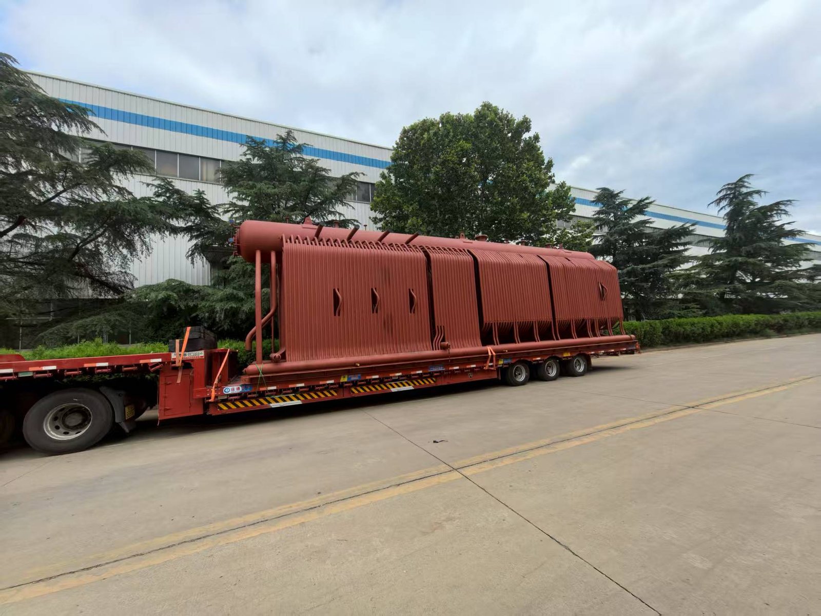
FOB Boiler Delivery Example: This 15 TPH industrial steam boiler project shows the equipment preparation and shipment stage of an overseas boiler supply. For international projects, the FOB equipment price represents only part of the total investment, while freight, site installation, civil works, electrical integration, commissioning, and other project costs must be evaluated separately.
EPC or turnkey delivery stacks several cost layers on top of the equipment price. Detailed engineering alone (P&IDs, structural analysis, electrical single-line drawings, DCS architecture, equipment layout) typically runs 8%–15% of the boiler cost for a moderately complex installation. Civil works — concrete foundations, anchor bolt systems, trenching for condensate return — add another layer. Electrical hookups, instrumentation loops, and DCS/PLC integration add more still. Insulation and cladding on both the boiler body and the connecting ductwork is often treated as an afterthought, but on a unit handling 600°C flue gas it’s neither cheap nor optional.
Taken together, EPC delivery typically adds 40%–120% on top of the FOB equipment price. Where you land in that range depends heavily on site complexity: a greenfield installation in a remote location with no existing utilities at the boundary sits near the top; a replacement unit sliding into an existing foundation and tying into an established DCS sits near the bottom. Plants in regions requiring IBC seismic design or hurricane wind load calculations will also push toward the higher end simply from the additional engineering hours.
The Bypass Damper: A Critical Item That Disappears From Early Quotes
One line item that routinely vanishes from preliminary quotations is the bypass damper and gas diverter valve system. For any production facility — cement kiln, steel reheat furnace, glass tank — process continuity means you cannot shut down the kiln just because the WHRB needs a tube inspection or a soot blower repair. The diverter damper lets you take the boiler offline while the production line keeps running, redirecting flue gas to the existing stack or atmosphere.
For large duct cross-sections — anything around 2 m × 3 m and above, which is common on cement preheater exits — motorized or pneumatic diverter dampers run $25,000–$120,000 depending on duct size, operating temperature, leakage class, and whether you need redundant actuators for fail-safe operation. High-temperature applications above 700°C require refractory-lined damper blades and specialized sealing, which pushes cost toward the upper end. Omitting this item from the scope to win a lower headline price is a short-sighted decision; the first unplanned WHRB outage that forces a kiln shutdown will cost more in lost production than the damper would have.
Bypass diverter dampers are optional on waste heat recovery boiler installationsFalse
For any continuous-process plant (cement, glass, steel), a bypass damper is operationally mandatory. Without it, any WHRB maintenance event requires a full process line shutdown, which typically costs far more in lost production than the damper hardware and installation.
Civil and Structural Costs: The Foundation Nobody Budgets For
WHRB modules in cement and steel plant applications are frequently elevated 6–15 m above grade. This isn’t an arbitrary design choice — it allows the natural draft created by the temperature differential to move flue gas through the system without a dedicated induced-draft fan in every configuration, and it keeps the boiler clear of ground-level equipment traffic.
That elevation means structural steel. A support frame, access stairways, maintenance platforms at drum level, and handrail systems for a mid-size installation (say, 20–40 t/h steam output) can easily run $80,000–$300,000 in fabricated structural steel and erection labor. For larger units, or sites where the structural frame also has to support connected ductwork and expansion joints, costs climb further.
Seismic zone requirements compound this. Plants in active seismic zones — parts of Southeast Asia, the Middle East, South America — must design the support structure to IBC or local equivalent standards, which changes member sizing, connection detailing, and the engineering hours required. Wind load calculations for exposed installations in coastal or high-altitude sites add similar scope. Neither of these is exotic engineering, but both must be scoped and priced before the project budget is locked, not discovered during detailed design.
In practice, the buyers who avoid budget overruns on WHRB projects are the ones who push suppliers for a fully scoped EPC breakdown early — not a clean FOB number they can take to finance, but a line-item estimate that separates equipment, civil, structural, electrical, and commissioning costs from the start.
Auxiliary Equipment and Balance-of-Plant Costs: Deaerator, Feed Pump, Economizer, and Control System
The boiler itself is often only 40–60% of what a complete, functional WHRB system actually costs on-site. Buyers who quote just the pressure vessel and heat exchange surfaces routinely run into budget overruns once the balance-of-plant scope gets properly defined. These auxiliary items are not optional add-ons — without them, the boiler either doesn’t run reliably or fails prematurely.
Feedwater Treatment and Deaeration
Water quality is where I’ve seen the most avoidable damage in the field. Dissolved oxygen and hardness minerals attack boiler tubes from the inside, and the failure mode is slow, invisible, and expensive. Pitting corrosion in the economizer or lower drum circuits often doesn’t show up until the next statutory inspection — by which point you’re looking at tube bundle replacement, not just chemical dosing.
A thermal deaerator — spray type for smaller units, tray type where you need tighter dissolved oxygen control (typically below 0.007 mg/L) — sized to match your WHRB steam output will run roughly $15,000 to $80,000. Where you land in that range depends mostly on rated capacity, whether you need a storage vessel sized for cold-start volume, and whether the unit ships with integrated pressure controls or you source those separately.
Upstream of the deaerator, raw water quality determines your treatment train cost more than almost anything else. A site drawing from a municipal supply with moderate hardness might get away with a straightforward softening system and antiscalant dosing. A plant pulling from a river or borehole with high TDS, silica, or chloride content needs reverse osmosis, sometimes a two-pass RO, or an ion exchange polisher. Budget $20,000–$150,000 for this piece — and be honest about your source water analysis before locking in that number. Skipping or undersizing water treatment is, without question, the single most common root cause of premature tube failure in WHRBs operating across cement, steel, and glass plants. The capital saved rarely covers even one tube bundle repair.
Feed Pump, Steam Drum Internals, and Attemperator
A duplex boiler feed pump set — one duty, one standby, which is non-negotiable for any continuous process application — costs roughly $8,000 to $60,000 depending on flow rate, discharge pressure, and whether you specify mechanical seals or packed glands. Stainless wetted parts add cost but are worth it in chemically aggressive condensate return systems.
Inside the steam drum, cyclone separators and chevron-type demisters do the unglamorous work of keeping steam dryness at or above 99.5%. Budget $5,000–$25,000 for this internals package. It sounds like a minor line item until you start seeing carryover contamination in your steam header fouling downstream process equipment.
For superheated steam applications — common in WHRBs serving power generation or high-temperature process steam users — you’ll need an attemperator with a spray control valve to regulate superheat temperature under varying flue gas conditions. That adds $10,000–$40,000 to the scope, and it requires a properly tuned control loop to avoid thermal cycling damage to the superheater tubes.
Instrumentation and Control System
A standalone PLC-based control panel covering pressure, temperature, drum level (typically three-element control), and flow transmitters runs $30,000–$90,000 for a mid-range WHRB. That range is heavily influenced by the number of I/O points, transmitter specification (standard vs. SIL-rated), and whether the panel builder is local or supplied from the boiler manufacturer’s own controls shop.
Integration into an existing plant DCS via Modbus RTU, Profibus DP, or OPC-UA is where engineering hours accumulate fast. Expect $15,000–$50,000 for this work, and plan for it early — retrofitting communications architecture late in a project is painful and invariably costs more than doing it right during the FEED stage.
For EPC projects with remote monitoring requirements, a SCADA interface and historian server add further to the upfront bill. In practice, though, plants that invest here tend to recover the cost within a year or two through earlier fault detection, reduced unplanned downtime, and the ability to optimize flue gas bypass damper control without sending someone to the roof in the middle of the night.
Omitting proper feedwater treatment is the leading cause of premature tube failure in waste heat recovery boilers.True
Dissolved oxygen, hardness scaling, and silica deposition attack boiler tube surfaces from the waterside. Industry inspection data and boiler OEM failure analysis reports consistently identify inadequate water treatment as the primary root cause of tube pitting, deposit-induced overheating, and shortened pressure-part service life.
BOP Component
Typical Cost Range (USD)
Key Cost Driver
Thermal deaerator
$15,000 – $80,000
Capacity, storage volume, pressure class
Water treatment plant (RO/IX)
$20,000 – $150,000
Raw water quality, TDS, silica, chloride
Duplex feed pump set
$8,000 – $60,000
Flow rate, discharge pressure, seal type
Steam drum internals
$5,000 – $25,000
Steam output, dryness specification
Attemperator + spray valve
$10,000 – $40,000
Superheat temp range, control precision
PLC control panel
$30,000 – $90,000
I/O count, transmitter spec, SIL rating
DCS integration
$15,000 – $50,000
Protocol, engineering hours, site complexity
Taken together, a reasonably complete BOP package for a mid-sized WHRB — say 10–30 t/h steam output — typically adds $100,000 to $400,000 on top of the boiler purchase price. That range is wide because raw water quality and existing plant infrastructure vary enormously between sites. The plants that budget accurately are the ones that get a site water analysis and a single-line P&ID developed before they ask for a formal quotation.
Annual Operating Costs: Water Treatment, Energy Consumption, Inspection, and Staffing
Once the capital expenditure is signed off and the WHRB is commissioned, the real cost conversation shifts to what you’re spending every year just to keep the unit running safely and efficiently. For a lot of plant financial controllers I’ve spoken with, this is where the budget model falls apart — the capital estimate was solid, but the annual operating line was a rough guess or simply missing.
Water Treatment: The Cost Nobody Wants to Calculate Until There’s a Tube Failure
Feedwater chemistry is not optional. Scale buildup of even 0.5 mm on evaporator tubes can raise metal temperatures enough to accelerate creep, and in a high-temperature WHRB with flue gas inlet temperatures above 600°C, that failure mode is fast and expensive. Oxygen corrosion is similarly unforgiving on economizer tubes, especially during startup/shutdown cycling.
For a 20 t/h WHRB operating continuously, the chemical dosing program typically covers three categories: oxygen scavengers (sodium sulfite is standard for lower-pressure systems; catalyzed sodium sulfite or DEHA-type alternatives are common above 4 MPa), scale inhibitors or anti-scaling polymers, and pH-conditioning agents to keep boiler water alkalinity in the right window — usually pH 10.5–12 depending on design pressure. The annual chemical cost for this kind of unit runs roughly $8,000–$25,000, but that range is genuinely wide because it depends on your makeup water quality (hardness, dissolved oxygen, TDS), whether you have a properly sized softener and deaerator upstream, and local chemical prices, which vary dramatically between, say, Southeast Asia and the Middle East.
Blowdown losses compound this. Continuous blowdown to control dissolved solids typically runs 1%–3% of steam output on a reasonably managed system; intermittent blowdown adds another 0.5%–2% during peak TDS periods or after upsets. At 20 t/h that’s a real water and energy loss that shows up in utility bills, not just chemical spend. Plants running on expensive municipal water — or in water-scarce regions — feel this more acutely.
Parasitic Power: Small Numbers That Add Up
The auxiliary power load on a WHRB is easy to underestimate because each component seems small in isolation. Feed pumps, induced draft fans, soot blowers (rotary or lance type), and the control system together typically draw 15–80 kW continuously on a mid-sized unit. The range is that wide because it depends heavily on duct pressure drop design, whether supplementary firing is included (which adds FD fans), and how aggressively the soot blowing schedule is run — some plants blow soot every 4 hours in high-ash flue gas applications, which adds up.
At an industrial electricity tariff of $0.06–$0.12/kWh, that parasitic load translates to roughly $8,000–$55,000 per year. The higher end of that range — say, an 80 kW load at $0.10/kWh — is $70,000 annually, which is not trivial against a $300,000 capital investment. This is one reason that duct and fan sizing deserves more attention during basic engineering than it usually gets. A poorly designed duct with unnecessary bends adding 200–400 Pa of extra pressure drop will cost you every single year for the life of the plant.
No claim provided.True
Based on a continuous auxiliary load of 80 kW operating 8,000 hours per year at $</span></span></span></span>0.08–$0.10/kWh, consistent with published industrial electricity tariff ranges and typical WHRB auxiliary equipment specifications.
Inspection, Certification, and the Staffing Line You Cannot Skip
This is the fixed-cost block that surprises buyers who are used to purchasing unfired heat exchangers. Pressure vessels above roughly 0.1 MPa are regulated in virtually every industrial jurisdiction — China, the EU, the US (ASME), Southeast Asia under various local codes — and compliance has a real annual price tag.
Annual or biennial internal inspection by a certified boiler inspector typically costs $2,000–$8,000 per inspection, depending on inspector availability in your region and the complexity of the unit. Remote or island sites pay more. Pressure vessel re-certification (hydrostatic test, NDE, documentation review) is typically required every 4–6 years and costs more again — budget separately for that cycle.
Then there’s the operator. Most jurisdictions legally require a licensed boiler operator on-site whenever the unit is under pressure above a defined threshold. Depending on country, that salary runs $30,000–$80,000 per year — Indonesia and Vietnam are at the lower end, while operators in Western Europe or Australia push toward the top. Shared operators covering multiple boilers can reduce the per-unit cost, but you still need qualified coverage for all operating hours.
An operational warning worth stating plainly: skipping or delaying statutory inspections to save $3,000–$5,000 is a category of false economy that has resulted in pressure vessel incidents and, more commonly, regulatory shutdowns lasting weeks. The inspection cost is small relative to the downtime exposure.
Rolling all of this together — water treatment, auxiliary power, inspection, and one allocated operator — annual operating costs for a mid-sized WHRB in the 15–30 t/h range typically fall in the $60,000–$180,000 per year band. The actual number depends heavily on local labor and energy rates, water quality, and how rigorously the unit is maintained. This is the figure that belongs in your lifecycle cost model and ROI calculation, not a vague “low maintenance” assumption.
Maintenance is where a lot of WHRB projects quietly bleed money — not through any single catastrophic failure, but through deferred cleaning, patched refractory, and overhauls that get pushed back until a tube failure forces the issue. A realistic maintenance budget starts with understanding what actually degrades in service and how fast.
Tube-Side Fouling and Soot Deposition
In cement kiln applications specifically, alkali dust — mostly potassium and sodium sulfate compounds carried in the kiln exhaust — deposits on tube banks faster than most plant engineers expect the first time they run one of these systems. Heat transfer coefficient loss of 15%–40% within a few weeks of startup is not unusual if the gas inlet temperature sits above 350°C and the kiln is processing a high-alkali raw mix. That’s not a conservative estimate; it’s a real operational range, and where exactly you land depends on the raw material chemistry, gas velocity through the tube banks, and whether finned or bare tubes were specified.
Online rapping systems — mechanically actuated vibrators mounted on tube bank frames — help enormously here. Installed cost runs roughly $5,000–$20,000 depending on how many rapping points the unit has and whether the controls are integrated into the main SCADA or run standalone. The investment pays back quickly if it reduces hydroblasting frequency from every three months to every twelve. Offline hydroblasting of tube banks typically costs $3,000–$15,000 per event; that spread comes down to unit size, tube bank accessibility (some designs are genuinely difficult to get a lance into), and whether your own crew does it or you bring in a specialty cleaning contractor. For a moderate-dust-loading application, budget one to two events per year at minimum. High-loading kilns or glass furnace WHRBs may need quarterly attention.
Refractory Lining: The Cost People Forget Until It Fails
The inlet gas duct and first-pass enclosure of any WHRB handling gas above roughly 650°C will be lined — either with dense castable refractory rated to 1,200°C or with ceramic fiber module systems, sometimes both in a composite arrangement. Neither is maintenance-free. Castable refractory develops thermal cycling cracks; ceramic fiber compresses and loses insulating value over time. Gradual startup and shutdown procedures genuinely extend refractory life — fast thermal transients are the primary damage mechanism, not just operating temperature. A plant that trips the upstream process repeatedly (power instability, upstream equipment issues) will eat through refractory faster than one running steady 24/7.
Partial refractory repair — patching cracks and spalled sections during a scheduled outage — runs $10,000–$30,000 in materials and labor for a mid-sized unit. A full reline of the first pass and inlet duct on a 30–60 t/h WHRB can reach $40,000–$60,000. Plan for this roughly every 3–7 years; the actual interval depends on how thermally stable your upstream process is and how disciplined the operators are with startup/shutdown ramp rates.
Refractory lining repairs in high-temperature WHRB inlet sections are typically required every 3–7 years under normal operating conditions.True
Thermal cycling and sustained high inlet gas temperatures above 800°C cause progressive castable cracking and ceramic fiber module compression; repair intervals in cement and steel plant WHRBs observed in practice confirm this range, with shorter intervals where process upsets are frequent.
Planned Major Overhauls: 5-Year and 10-Year Schedules
This is where most maintenance budgets are underfunded, because the costs are real but infrequent enough to get deprioritized during budget cycles.
A 5-year planned overhaul on a 20–50 t/h unit — covering ultrasonic tube wall thickness mapping, drum internal inspection (pitting, deposit survey, nozzle weld checks), safety valve overhaul, control valve and actuator servicing, and instrument calibration — typically runs $40,000–$150,000 all-in. The range is wide because tube condition varies significantly: a unit on well-treated feedwater with clean gas may need only minor work; one that’s been run hard or had water quality lapses may need tube plugging or selective bundle replacement at the same outage.
At the 10-year mark, superheater tube replacement is often on the table. If the superheater is fabricated from high-alloy material — TP304H or TP347H stainless, or T91 in high-pressure units — replacement cost for a full bundle runs $80,000–$250,000 depending on the alloy, the bundle geometry, and whether the design allows staged replacement or requires a full pull. Budget from the bottom of that range for a straightforward bare-tube counterflow superheater on a simple single-drum design; approach the top if you’re dealing with a multi-pass unit with complex headers.
The practical recommendation: set up a sinking fund from commissioning, allocating roughly 1.5%–2.5% of the installed capital cost annually. For a $400,000 system, that’s $6,000–$10,000 per year reserved — small enough not to sting, large enough that a $100,000 overhaul at year five doesn’t land as an unplanned capital event.
Maintenance Activity
Typical Cost Range
Frequency
Key Cost Driver
Tube bank hydroblasting
$3,000–$15,000/event
Every 6–18 months
Dust loading, unit size
Online rapping system (install)
$5,000–$20,000
One-time capital
Number of rapping points
Refractory patch repair
$10,000–$30,000
Every 2–4 years
Thermal cycling frequency
Full refractory reline (first pass)
$40,000–$60,000
Every 5–7 years
Inlet temperature, process stability
5-year planned overhaul
$40,000–$150,000
Year 5, 10, 15
Unit size, condition, water quality history
Superheater bundle replacement
$80,000–$250,000
~Year 10+
Alloy grade, bundle geometry
Deferred maintenance on WHRBs usually manifests as forced outages rather than gradual performance loss — a tube failure in the convection bank, refractory spall blocking gas flow, or a drum nozzle weld that fails an inspection. None of those are cheap to fix on an emergency basis, and all of them are foreseeable.
Lifetime Economics and ROI Calculation: Payback, IRR, and the Break-Even Fuel Credit Model
The purchase price of a waste heat recovery boiler is, frankly, the easiest number to get. The harder question — the one that actually determines whether a project gets approved at the board level — is what the asset returns over its operating life. Get the ROI framework wrong and you either kill a genuinely strong project or, worse, approve a marginal one that never pays back.
The Fuel-Credit Method: What Your WHRB Is Actually Worth Per Year
The most defensible approach for justifying capital expenditure is the steam-substitution or fuel-credit model. The logic is simple: every ton of steam your WHRB generates is a ton you are not raising in a fired boiler. Price that avoided cost correctly and you have your annual benefit figure.
Take a concrete example. A 20 t/h WHRB producing saturated steam at 1.3 MPa, recovering heat from a cement kiln’s preheater exhaust at roughly 380–420°C. At a fuel oil equivalent cost of around $70 per ton of steam — a reasonable figure for heavy industry in Southeast Asia or the Middle East, though it shifts with bunker fuel pricing — annual steam production over 7,500 operating hours comes to approximately 150,000 tons, carrying a gross fuel-credit value near $1,050,000–$1,200,000. Subtract realistic annual O&M of $80,000–$150,000 (tube inspection, water treatment, soot blowing consumables, control calibration), and your net annual benefit lands somewhere in the $900,000–$1,100,000 range. Against a total installed project cost of $800,000–$1,500,000 for a unit of that capacity, simple payback works out to roughly 0.7–1.3 years. That is an unusually strong case, and it exists precisely because a cement kiln runs nearly continuously with high-temperature, high-volume exhaust.
Not every project looks like that. Batch processes, lower gas temperatures, and plants with significant seasonal shutdowns can push payback out to 4–5 years or beyond.
Three Variables That Move the Numbers More Than Anything Else
Flue gas inlet temperature is the single biggest swing factor in WHRB economics. Below roughly 300°C, the recoverable enthalpy per unit of gas volume drops sharply, heat transfer surface requirements increase, and unless you are dealing with very large gas flow rates — say, 150,000+ Nm³/h — the economics become marginal. In my experience reviewing project feasibility studies, this is where a lot of optimistic proposals quietly fall apart.
Plant operating hours matter enormously and are frequently understated in early-stage models. A WHRB at a cement plant logging 7,500 hours per year generates roughly 2.5 times the annual savings of an identical unit at a 3,000-hour batch glass plant. That ratio directly scales every line in the financial model.
Local energy tariff is the third lever. Every $10/MWh increase in the applicable electricity or steam cost reduces simple payback by somewhere between 15% and 25%, depending on plant capacity and fixed cost structure. In regions with subsidized industrial energy — certain Gulf states, parts of China — payback periods can stretch to 5–7 years even for otherwise well-specified projects.
Stress-test all three variables in your sensitivity table before you commit to a project budget. A base-case payback of 2.5 years can easily become 5 years if gas temperature runs 60°C lower than the design point, which happens more often than process engineers like to admit.
IRR Benchmarks by Industry
Cement plant WHRBs consistently deliver IRR in the 25–45% range when the kiln operates above 7,000 hours per year and flue gas inlet temperature exceeds 320°C.True
Cement kilns produce large, continuous, high-temperature exhaust streams from both the preheater and cooler stages, making them among the most favorable WHRB applications globally. IRR in this range is corroborated by project data from multiple EPC installations in Asia, the Middle East, and Africa.
Steel electric arc furnace off-gas WHRBs typically show IRR of 18–30%. The variability comes from tap-to-tap cycle irregularity — EAF exhaust is pulsed rather than continuous, which requires careful steam drum sizing and accumulator design to smooth the recovery curve. Glass furnace applications, where the regenerative cycle complicates integration, generally land at 15–25% IRR. Diesel genset jacket heat recovery, usually producing hot water rather than steam, can reach 20–35% IRR at sites with high genset load factors, mainly because the capital cost of a hot-water WHRB is considerably lower than a steam system.
Any project showing a projected IRR below about 12% deserves hard scrutiny. That threshold usually signals one of three problems: marginal inlet gas temperature, insufficient annual operating hours, or a total installed cost that crept up during engineering. In those cases, it is worth re-scoping — sometimes downsizing capacity, sometimes reconsidering whether an economizer-only solution or a waste heat hot-water system makes more sense than a full steam-generating WHRB.
The financial model is only as good as the process data feeding it. Get the gas flow measurements and temperature profiles from actual operating conditions, not design-case assumptions.
Procurement Checklist and Supplier Qualification Criteria for International WHRB Projects
Buying a waste heat recovery boiler across borders is not like ordering a standard fire-tube package unit. The technical stakes are higher, the inspection access is harder, and the cost of getting the supplier selection wrong — a tube bundle that erodes in eight months instead of four years, a drum that fails hydro-test on arrival, a controls package with no local support — lands directly on your shutdown schedule and your insurance claim.
Start with certification, and be specific in the RFQ.
Mandatory Design Standards: Write Them Into the Tender Document
Don’t leave this vague. If your installation is in North America or a country that accepts ASME stamps, specify ASME Section I for the boiler pressure parts (drums, headers, tubes operating under steam pressure) and ASME Section VIII Div.1 for any unfired pressure vessels in the circuit — the steam drum separator, flash vessels, that sort of thing. European installations require CE marking under the Pressure Equipment Directive (PED 2014/68/EU), with the boiler classified in the correct category based on design pressure and DN. Indian projects need IBR (Indian Boiler Regulations) certification, and the drawings must be approved by the relevant state boiler inspectorate before erection — skipping this step is not a shortcut, it’s a six-month delay waiting for you later.
For China-manufactured equipment exported internationally, the relevant domestic standards are GB/T 16507 (water-tube boilers) and TSG G0001 (boiler safety supervision regulations). A credible manufacturer should be able to supply these alongside third-party witness inspection — typically by SGS, Bureau Veritas, or TÜV — covering material traceability, welding procedure qualification, and hydro-test. The critical question is whether the supplier holds these certifications in-house. Subcontracting pressure-part fabrication to an uncertified shop and then applying a certified manufacturer’s stamp is a real practice in lower-tier supply chains. Ask for the actual ASME Certificate of Authorization or the TSG manufacturing license number, and verify it directly with the issuing body.
Supplier Capability: What to Actually Verify
A factory visit tells you more in two hours than a brochure tells you in two years. Look for in-house CNC tube-to-header welding with WPS/PQR records on file — not just a statement that they “follow AWS D1.1” but actual qualified procedures covering the base materials and filler metals used in your specific unit. RT and UT capability should be on-site; if all radiography is sent out, ask who the subcontracted NDT firm is and what the turnaround time looks like during peak production.
Hydraulic pressure testing to 1.5× design pressure is standard; the question is whether the customer can witness it. Insist on a formal FAT protocol written into the contract, with the option to send your inspector or a third-party inspector to the shop. Some suppliers offer remote FAT via live video — acceptable for lower-risk units, but for a 50 t/h unit at 3.8 MPa with a novel gas composition, you really want someone physically present.
3D thermal and flow simulation (CFD) matters more than buyers often realize. Non-standard duct geometries — a converter gas duct with a 90° bend feeding directly into the first tube bank, for instance — create uneven velocity profiles that accelerate erosion on the leading tubes. A supplier that can show you the simulated flow field and explain how the tube pitch and baffle arrangement were adjusted in response is doing real engineering. One that hands you a standard layout without any analysis of your specific gas path is guessing.
Ask for a reference list. Specifically: same industry, similar inlet gas temperature (within roughly ±80°C), similar dust loading, and comparable steam output. A supplier with twenty delivered units in cement kiln tail-gas recovery has genuinely different experience from one whose WHRB references are all clean natural gas heat exchangers.
Contract Terms That Protect You Through the Whole Asset Life
The thermal efficiency performance guarantee should be quantified — something like “minimum 82% recovery of available waste heat enthalpy at design gas flow and inlet temperature” — not a vague statement about “high efficiency.” Tie liquidated damages to it if the project economics depend on a specific heat recovery rate.
Tube erosion warranty is worth negotiating hard, especially for high-dust applications like cement preheater exit gas or EAF off-gas. Specify the design dust loading (in g/Nm³) in the contract, and link the warranty period to that figure. If actual dust loading exceeds the design value, that’s an operational risk to manage; if it’s within spec and tubes fail early anyway, that’s a supplier problem.
A reputable WHRB manufacturer should include a years 1–3 spare parts package — covering tube bundles, gaskets, control valves, and critical instruments — as a standard contract option, not an afterthought.True
First-year failures are disproportionately common in WHRBs due to commissioning upsets, thermal cycling during startup, and process gas conditions that deviate from design. Having OEM-specified spares on-site reduces mean-time-to-repair from weeks (international freight lead times) to days.
Remote technical support and commissioning assistance should be contractually defined — not “we will provide support” but “a qualified commissioning engineer will be on-site for a minimum of X days during first fire and performance testing.” For projects in Southeast Asia, the Middle East, or Africa, ask directly whether the supplier has authorized service partners or resident engineers in your country. Shipping a technician from China or Germany for a two-day fault diagnosis costs more than people budget for, and takes longer.
Frequently Asked Questions About Waste Heat Recovery Boiler Costs
These are the questions that come up repeatedly — from plant engineers doing a feasibility study at midnight, from procurement managers comparing three supplier quotes that don’t line up, from EPC project managers trying to explain a budget overrun to a client. The answers below are not textbook definitions; they’re the kind of clarifications that prevent expensive mistakes.
What is the minimum flue gas temperature for a WHRB to be economically viable?
Sustained inlet gas temperatures above roughly 300°C are the practical floor for steam-generating WHRB applications. Below that threshold, the heat flux across the tube bundle drops enough that steam generation becomes borderline — you’re spending serious capital on a pressure vessel and all its auxiliary systems to recover heat that a simpler device could handle. Between about 200°C and 300°C, a hot water WHRB or a thermal oil heater is usually the more sensible choice, particularly for process heating loads that don’t need steam pressure. Below 200°C, you’re generally better served by a condensing economizer or a direct air preheater; installing a full boiler system at those temperatures rarely pencils out unless there’s a very cheap financing arrangement or an unusually high local energy cost.
What actually complicates this rule is that “sustained” is doing a lot of work in that sentence. A rotary kiln that runs 340°C average but dips to 220°C during start-up cycles will stress a steam drum system and may cause condensation fouling in the economizer tail. Temperature profile matters as much as peak temperature.
Can a WHRB be added to an existing plant without stopping production?
Yes — but only if the installation design includes a properly engineered bypass damper and diverter valve system from the start. The sequence is straightforward in principle: during a planned maintenance shutdown, the WHRB and its connecting ductwork are inserted into the flue gas path; the bypass damper then allows the process to resume while commissioning continues on the steam side. In practice, damper sizing for high-temperature, high-dust gas streams is a real engineering task, not a line item to cut to save money.
That damper system typically adds $25,000–$120,000 to the project depending on duct diameter, gas temperature, and whether the damper needs to be actuated under pressure. For continuous-process industries — cement, float glass, electric arc furnace steelmaking — it’s non-negotiable. Plants that skip it find themselves forced into a hard production stop at installation, which in a cement plant can mean days of lost output that easily exceeds the damper cost.
How does a waste heat recovery boiler differ from an HRSG used with gas turbines?
Both recover exhaust heat to generate steam. The similarity mostly ends there. An HRSG is engineered around the clean, well-characterized exhaust of a gas turbine — typically 450–600°C, very low particulate loading, predictable flow rate, and no significant corrosive species. Tube pitch can be tighter, soot blowing is minimal or absent, and material selection is relatively straightforward.
A WHRB handles what industrial processes actually produce: dust-laden gas from a clinker cooler, SO₂-bearing flue gas from a sulfur recovery unit, zinc oxide fumes from an EAF, or variable-temperature exhaust from a batch glass furnace. Tube spacing has to be wide enough to prevent bridging and blockage. Cleaning systems — whether acoustic horns, rapping gear, or retractable sootblowers — are not optional. In sulfur-bearing streams, the economizer tube material may need to step up from carbon steel to ND steel or even 09CrCuSb to resist low-temperature corrosion.
HRSG and WHRB are interchangeable terms in industrial specificationsFalse
They are distinct equipment categories with different tube spacing, cleaning system requirements, and material selection logic. Using HRSG specifications for a WHRB application in a cement or steel plant will result in tube fouling, accelerated corrosion, and early failure.
Using the terms interchangeably in a technical specification is the kind of mistake that leads to a tube bundle replacement three years into a twenty-year project.
What is the typical lifespan of a WHRB, and when should major components be replaced?
A well-maintained WHRB with correct water chemistry should reach 20–30 years of structural service life. That figure assumes periodic NDT thickness measurement on the drum and headers, per whatever pressure vessel code governs the installation — ASME Section I, EN 12952, GB/T 16507, or equivalent. Drums don’t typically fail on a schedule; they fail when water treatment is neglected or when inspection intervals slip.
Component replacement schedules are more predictable. Superheater tubes in high-temperature, high-pressure service — say, 480°C steam at 6 MPa — generally need replacement somewhere in the 10–15 year range, depending on flue gas composition and operating hours. Economizer tubes in sulfur-bearing gas streams are more aggressive: 7–12 years is realistic, sometimes less if the plant frequently shuts down and allows the tube surface to cool below the sulfuric acid dew point. Refractory lining in the inlet section of a high-temperature WHRB (900°C+ inlet) typically requires patching every 3–5 years and full replacement at 10–15 years.
Is financing or leasing available for WHRB projects, and how does this affect total cost?
Energy Performance Contracting — not to be confused with Engineering-Procurement-Construction, which shares the same abbreviation — allows a third-party investor to fund the WHRB installation and recover that investment from the measured energy savings over a contracted period, usually 5–10 years. The plant owner gets the system with zero upfront capital. The trade-off is total cost: over the contract term, the plant will typically pay 20%–40% more than it would have spent on a direct purchase, once financing costs and the performance contractor’s margin are factored in.
For international projects, green bonds and carbon credit monetization have become increasingly relevant, particularly in jurisdictions with active voluntary carbon markets. Export credit agency financing from the boiler manufacturer’s home country is another mechanism worth exploring — it can significantly reduce the effective interest rate on equipment loans for buyers in emerging markets, though the paperwork and timeline involved should not be underestimated. None of these financing structures change the underlying equipment cost; they change who pays, when, and at what premium.