Commissioning a waste heat recovery boiler without a structured safety protocol in place is one of the faster ways to turn a capital project into a liability. Thermal shock to cold pressure parts, undetected tube leaks going into first steam raise, drum water level swings during transient heat-up — any one of these can force an immediate shutdown, crack a weld, or in the worst cases escalate to a pressure event. The downstream cost is rarely just the repair bill; it’s the idled upstream process, the delayed production ramp, and the contractual penalties that follow when a cement kiln or glass furnace sits waiting on a boiler that wasn’t ready.
Safe WHRB commissioning requires completing hydrostatic testing at 1.25–1.5× design pressure before any thermal loading, maintaining drum water level within ±25 mm of the normal working level throughout heat-up, verifying all safety valve lift pressures, purging the gas-side of combustible accumulations, and establishing clear hold points with signed permit-to-proceed authority at each phase transition.
What makes waste heat recovery boilers genuinely different from a conventional fired boiler — and where a lot of commissioning teams underestimate the risk — is that the heat source is not something you throttle with a fuel valve. Whether you’re taking exhaust off a gas turbine at around 500 °C or raw converter gas from a steel plant pushing past 1,000 °C, the upstream process sets the pace. That asymmetry changes how you sequence safety checks, how you plan your hold points, and frankly how much margin you build into your first few heat-up cycles.
Pre-Commissioning Inspection Checklist: Pressure Parts, Refractory, and Ductwork Integrity
Before a single liter of feedwater enters the drum or any process gas gets admitted through the inlet duct, every major mechanical subsystem needs a structured, documented walkdown. Not a casual once-over — a formal hold point with sign-off. Skipping or rushing this stage is where most commissioning problems originate, and in a WHRB the consequences tend to cascade: a cracked expansion joint doesn’t just leak, it lets hot gas bypass into insulated cavities where nobody sees it until there’s a structural failure or a fire in the lagging.
Pressure-Part Dimensional and Weld Inspection
Start with the paperwork, then go to the hardware. Pull the fabrication as-built drawings and cross-reference drum nozzle orientations, header stub dimensions, and tube-to-header connection geometry against what’s actually installed. Discrepancies happen — field modifications made during erection don’t always find their way back to the drawing register. Every weld that was required to be radiographically or ultrasonically tested should have a numbered test record on file. Any area that underwent weld repair must have a re-examination record for that specific repair; a passed original weld report on a subsequently repaired joint is not acceptable.
Pay particular attention to dissimilar-metal joints and any field welds made in confined spaces — these get rushed and are statistically where you find rejectable indications. If records are missing, the right call is a targeted UT sweep before proceeding, not an assumption that it was done.
Refractory and Insulation Readiness
Refractory failures during early operation are almost always a curing problem, not a material quality problem. Inspect transition duct linings and any duct-fired sections for cracks, voids, delamination at anchor studs, and areas where the lining was poured or rammed against a surface that wasn’t properly primed. Even a correctly installed castable refractory holds residual moisture, and if you admit hot flue gas — especially at inlet temperatures above 600 °C, which is common in cement kiln or steel converter WHRBs — before that moisture is driven out, the steam pressure inside the lining will spall chunks off within the first few hours.
The mandatory dry-out curve typically runs 24–72 hours total, depending on lining thickness and castable type, holding at 50–80 °C first and stepping up to 110–120 °C before the final ramp. Some thick-wall linings need longer. Get the refractory supplier’s specific cure schedule in writing and follow it; a generic curve from the boiler datasheet may not match what was actually installed. Document each temperature hold with logged thermocouple data, not just a verbal confirmation from the site crew.
Expansion Joint and Support Verification
This one gets overlooked more than it should. All duct expansion joints, hanger rods, and spring supports are designed and set for a cold-position datum. During construction, temporary restraints — angle iron welded across expansion joint flanges, turnbuckles left locked, spring cans with shipping stops still in — routinely stay in place because no single person owns the job of removing them. When thermal cycling begins, those restrained joints can’t move, and the load transfers directly into tube-to-header welds.
Walk every support and hanger physically. Check spring can indicators against the cold-load setting on the spring schedule. Verify expansion joint control rods are in the correct cold-position setting. Sign and photograph each one.
Unreleased construction restraints on WHRB duct supports are a documented cause of tube-header weld cracking during first thermal cycling.True
Thermal expansion loads in large ductwork can reach several tonnes of force; if expansion joints cannot move freely, the load concentrates at rigid attachment points including tube-to-header connections, which are not designed for axial restraint loading.
Soot-Blower, Bypass Damper, and Isolation Valve Functional Checks
Every damper in the flue gas circuit needs to be stroked manually — fully open, fully closed, back to intended operating position — before commissioning starts. Check blade seating visually; worn or warped blades that look closed on the actuator position indicator can be passing 15–20% of design gas flow. The bypass damper is your emergency divert path. If it won’t open fully and quickly on demand, you have no safe way to protect the WHRB during an upstream process upset.
Soot blowers should be cycled dry (no steam, just mechanical travel) to confirm travel limits, lance retraction, and that nozzles are correctly aligned with tube banks. A lance that sticks extended and gets hit by process gas is an expensive problem.
Instrumentation and Safety Valve Pre-Checks
Verify every thermocouple, pressure transmitter, differential pressure level gauge, and flow element against the P&ID — not just “is it installed” but insertion depth, process connection orientation, and impulse line routing free of trapped pockets. Level gauges on the steam drum are safety-critical; a blocked impulse line gives a false level reading that operators will trust.
Safety relief valves must have current lift-test certification and set-pressure confirmation on file before hydrostatic test begins. Check that discharge piping runs to a safe location, is adequately supported (discharge reaction forces are substantial), and has no valves, blind flanges, or obstructions in the free-blowing path. This sounds basic. It gets missed.
Cleanliness and Foreign-Object Exclusion
A formal FOD walkdown of drum internals, steam separators, cyclone separators, and economizer headers is non-negotiable. Construction debris — weld rod stubs, gloves, rags, broken refractory chunks, nuts and bolts — routinely ends up inside pressure parts. Anything that blocks a downcomer orifice or a separator vane causes circulation problems that won’t be obvious until the unit is at operating pressure. Require a signed, itemized checklist with photographic evidence of open manholes and clean internals before final closure. Treat drum closure as a contractual hold point requiring owner or third-party inspector witness. This is not bureaucracy — it’s the last chance to see inside.
Hydrostatic Pressure Testing Procedures and Safety Controls
The hydrostatic test is the single highest-pressure event the boiler will ever experience in a controlled setting. Get it wrong and you’re dealing with catastrophic failure of pressure parts, serious injury, or at minimum a delayed project while you chase down a weeping weld that wasn’t caught earlier. The sequence below is how it should be run on a WHRB — not a fired boiler, not a generic vessel, a waste heat recovery unit with its own circuit complexity.
Test Pressure Parameters for Mixed-Pressure Circuits
Under ASME Section I and EN 12952, the hydrostatic test pressure sits at 1.25–1.5× the maximum allowable working pressure (MAWP), with the exact multiplier depending on which code applies and the age/edition of the documentation package. For a straightforward single-circuit unit that’s fairly routine. WHRBs, however, routinely combine a high-pressure steam-generating section with a low-pressure economizer or hot-water circuit — common in gas turbine exhaust and cement kiln applications where the flue gas inlet temperature might range anywhere from 350 °C up past 1,000 °C, and the thermal gradient design forces different pressure ratings across the same unit. Each circuit must be isolated and tested independently at its own design multiplier. Pressurizing the HP steam drum section to its test pressure while the LP economizer is still connected is a straightforward way to rupture economizer headers. This sounds obvious until you’re on a tight commissioning schedule and someone suggests a “combined fill” to save time. Don’t.
Water Quality and Temperature Requirements
Fill water must be deaerated and chemically treated — oxygen content below 0.1 mg/L, pH held between 9.5 and 10.5 with morpholine or sodium hydroxide/trisodium phosphate depending on your water treatment philosophy. Untreated water introduced at this stage leaves residual oxygen that begins pitting the internal surfaces before the unit ever fires, shortening tube life measurably.
Water temperature matters more than most site teams appreciate. Carbon steel drums and headers must be tested above the material’s ductile-to-brittle transition temperature — in practice, keep test water above 15 °C minimum, and above 20 °C if the ambient is cold and the drum wall is thick. Filling a cold drum in a January startup with water at 8 °C and then ramping to test pressure is exactly the scenario that causes brittle fracture with very little warning. This is not a theoretical concern; it is a specific failure mode documented in pressure vessel incident databases.
Pressurization Rate and Hold-Time Protocol
Pressurize in 25% increments of the final test pressure. Pause for a minimum of 10 minutes at each step. This allows the system to stabilize thermally and lets any pre-existing micro-cracks announce themselves before you’re at full load. Once you reach the target test pressure, hold it. The hold period should be no less than 20 minutes and ideally 30. During this hold, no visual inspection occurs — personnel stand clear of the exclusion zone. After the full hold, bleed pressure back down to the design working pressure, then and only then do inspectors approach for physical examination of joints, flanges, welds, and tube-to-header connections.
Exclusion Zone and Personnel Safety
Maintain a minimum 10-meter exclusion zone around any pressurized component during the hold period. No exceptions for “just a quick look.” Prohibit all percussive or impact work anywhere on the pressure system while it is under test — a hammer strike on a stressed drum is not a trivial risk. Two-way radio communication between the pressurization operator and the site safety officer must be confirmed active before pressurization begins.
A hydrostatic test at 1.25–1.5× MAWP per ASME Section I and EN 12952 confirms structural integrity of pressure parts before commissioningTrue
Both ASME Section I (PG-99) and EN 12952-6 require hydrostatic testing at a minimum multiplier of 1.25× MAWP (ASME) or 1.3× (EN 12952, depending on edition and circuit type) as a mandatory pre-service acceptance test for steam-generating pressure vessels.
Acceptance Criteria and Documentation
A passed test means: zero visible leaks at any point, pressure drop not exceeding 0.5% over the hold period (accounting for minor temperature effects on the gauge), and absolutely no visible permanent deformation of drums, headers, or structural attachments. Minor surface sweating at rolled tube ends warrants immediate investigation — it will not self-seal under operating conditions.
The test report is a formal hold-point document. It must be signed by the third-party boiler inspector, the client’s commissioning representative, and the Taisan engineering supervisor before any subsequent commissioning activity proceeds. No signature, no next step. This creates a clear chain of accountability that matters if questions arise later during insurance claims or regulatory audits.
Drain-Down and Interim Corrosion Protection
Once the test is complete, drain the system promptly. If hot commissioning follows within a few days, a dry-out procedure is usually sufficient. If the gap between hydro test and first fire is longer than roughly a week — which happens more often than project schedules admit — establish nitrogen blanketing at 0.03–0.07 MPa gauge to prevent oxygen ingress. Oxygen pitting in the idle period between hydro test and operation is a real source of premature tube failure that gets blamed on operating chemistry later. Don’t let that window go unprotected.
Cold Commissioning Phase: Water Fill, Venting, and Chemical Passivation Safety Steps
Cold commissioning is the phase most engineers rush through. The hydrostatic test is done, the paperwork looks good, and there’s pressure from the project schedule to get to first steam. Resist that pressure. The water fill and chemical treatment sequence has its own failure modes — some of them slow-acting and invisible until the hot phase, when fixing them is dangerous or impossible.
Controlled Water Fill Sequence
Always fill from the lowest point of the system upward. On a WHRB, that means starting through the economizer inlet connection, letting water displace air progressively toward the steam drum and then into the superheater circuits. The temptation to fill quickly from the drum top is understandable on a cold site in January, but it creates two problems: water hammer as fast-moving water hits trapped air columns, and — more seriously — air pockets that lodge in superheater loop headers and blind legs. Those pockets don’t get expelled during cold commissioning. When the upstream process gas (potentially 400–900 °C depending on whether you’re recovering from a glass furnace, a cement kiln exit, or a gas turbine exhaust) hits the superheater during the hot phase, those dry tubes flash and overheat locally. You might not see it immediately. You’ll see it three months later as tube blisters or a pinhole leak.
Fill rate should be slow enough that the drum level gauge rises at a steady, controllable pace — roughly 10–15 minutes from empty drum to normal working level is a reasonable target for most mid-sized WHRBs, though this depends on total water volume and available fill pump capacity.
Steam Drum Venting Protocol
Keep the drum air vent fully open from the moment you start filling until you see a continuous, unbroken stream of water at the vent outlet — not an intermittent air-and-water spray, which just means the drum is still partially air-filled. This sounds obvious, but I’ve seen loops get closed early because someone confused turbulent splash at the vent with actual flow confirmation. Once you close the vent, immediately cross-check the drum level gauge reading against the independent gauge glass. Both should read identically. If they diverge by more than a few millimeters, stop and investigate before proceeding. This dual-verification habit catches gauge isolation valve misalignment and blocked bridle connections — conditions that have caused serious low-water events during subsequent hot startup because operators trusted one gauge that was reading false.
Chemical Passivation and Alkaline Boil-Out
New pressure parts in a WHRB carry mill scale, threading compound residues, welding flux, and whatever construction contamination accumulated during erection. None of that belongs in your boiler water chemistry. The standard alkaline boil-out solution uses sodium hydroxide at roughly 3–5 kg per cubic meter of system water volume, combined with trisodium phosphate at 2–3 kg/m³. The exact concentrations depend on the degree of internal surface contamination, whether the pressure parts sat exposed for an extended erection period, and manufacturer recommendations — always confirm with the boiler OEM before mixing.
Chemical handling during boil-out preparation demands full face shield (not just safety glasses), chemical-resistant gloves and apron, and a neutralization kit positioned at the mixing point before you open any chemical containers. Ventilation matters: sodium hydroxide solution gives off heat and aerosol during mixing, especially if someone adds it too fast. Work slowly, add chemicals to water rather than water to chemicals, and keep at least two people present during mixing and drum injection.
Alkaline boil-out removes mill scale and oil residues from new WHRB pressure parts and is required prior to hot commissioning.True
This is standard practice per ASME and major WHRB OEM guidelines; mill scale and oil contamination degrade feedwater chemistry and can cause localized tube corrosion or fouling if not removed before first steam production.
Blowdown Safety During Boil-Out
Intermittent bottom blowdowns during the boil-out cycle are what actually expel the loosened deposits — without them, you’re just suspending contamination in the boiler water, not removing it. Conduct blowdowns at approximately 10% of design drum pressure, which keeps the energy low enough for safe drain line handling without losing so much water that you interrupt the thermal cycle.
Every blowdown during this phase requires written operator authorization on a signed work permit. Before the blowdown valve operator touches anything, a second person must verbally confirm drain valve position and monitor the drum level gauge continuously throughout the operation. The two-person rule here isn’t bureaucracy — it’s the gap between a controlled pressure event and an uncontrolled low-water condition developing faster than one person can track. Blowdown lines should be confirmed clear to safe drain locations before each cycle; construction debris in drain headers is more common than people admit.
Water Quality Release Criteria
Cold commissioning is not complete just because the drum is full and the boil-out is done. The phase only closes when laboratory-certified water analysis confirms the system meets chemistry specifications. Typical release targets: total dissolved solids below 500 mg/L, silica below 0.5 mg/L, and dissolved iron below 0.3 mg/L. These aren’t arbitrary — silica carryover into steam damages downstream turbine blades or process equipment, and elevated iron indicates that internal surfaces are still shedding corrosion products. Use a certified external laboratory, not just an in-house colorimetric kit, for the final sign-off sample.
Instrumentation Loop Checks
The cold fill phase gives you an unusually clean window to run full loop checks on drum level control, feedwater control valves, and automatic blowdown valves using simulated signals. Do this now. Once the upstream process is running and live flue gas is present, adjusting a misconfigured feedwater control loop under thermal load is significantly more hazardous and often requires process interruption. Walk each control loop from the field transmitter through the DCS output to the final control element, verify valve stroke and direction, and confirm alarm setpoints against the design basis. A drum level transmitter with its high and low alarms swapped is not a theoretical failure mode.
Hot Commissioning Phase: Controlled Hot-Gas Admission, Thermal Ramp Rates, and Steam Raising Safety
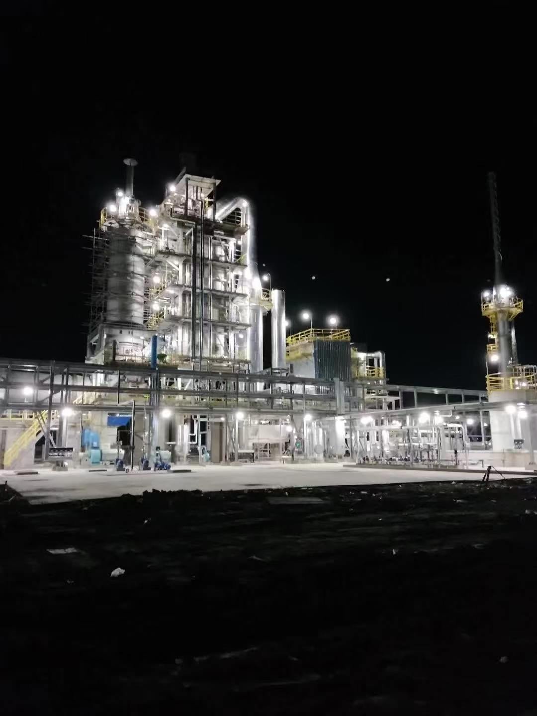
This is the phase where things actually go wrong. Cold commissioning has its hazards, but hot commissioning — first gas admission, thermal ramp-up, initial steam raising — is where the consequences of skipped steps show up fast and expensively. Tube failures, refractory spalling, steam hammer events, and missed interlock trips all cluster here. The sequence below is not a generic checklist; it reflects what disciplined field practice looks like on a real startup.
Coordination with the Upstream Process Operator
Before any damper is touched, the communication protocol needs to be locked down in writing. Designate a specific radio channel — or hardwired phone line — for WHRB-to-process communication, and name individual contacts on both sides. A written gas admission permission slip, signed by both the WHRB commissioning lead and the upstream process shift supervisor, should exist for every ramp step. This sounds bureaucratic until the moment the upstream operator increases kiln output without telling the boiler team.
The WHRB operator must hold independent authority to call for gas shut-off at any time, without needing approval from the process side. That authority has to be agreed before startup, not negotiated in the middle of a temperature excursion.
Hot-Gas Admission and Thermal Ramp Control
Open the bypass damper first. Always. Then admit flue gas through the WHRB in increments of roughly 10–15% of the main damper travel, with a minimum 30-minute stabilization hold at each step before proceeding. What you are watching during each hold is tube metal temperature stabilization, drum pressure response, and gas-side differential pressure across the tube banks.
Target a gas-inlet temperature rise rate not exceeding 50 °C per hour until the evaporator reaches saturation pressure. This matters most for inlet temperatures above roughly 600 °C — common on cement kiln or glass furnace WHRBs — where the thermal gradient between the gas-facing tube surface and the water-side can drive differential expansion fast enough to crack refractory seals or stress tube-to-header welds. Slower is almost always cheaper than a tube replacement mid-commissioning.
Steam Drum Pressure Rise Monitoring
Read drum pressure on at least two independent gauges — not the same instrument signal fed to two displays. Target a controlled pressure rise of 0.05–0.1 MPa per hour during initial steam raising; the actual rate depends on drum size, water inventory, and heat input, but slower is safer during first fire. Keep the drum steam vent open until you have confirmed clean, non-condensing steam flow. Closing it prematurely traps a steam-air mixture in downstream pipework, which creates ignition risk and also gives you a false sense of system readiness.
Walking the Boiler at Every Ramp Step
Assign one technician to physically walk the entire boiler structure at each ramp increment — not to read gauges, but to look and listen. Expansion joints that are binding, steam wisping from a flange face, a support spring that has bottomed out, pipe movement that does not look right. No SCADA system catches these. In practice, this person should carry a thermal imaging camera and a contact thermometer, and their observations go directly into the commissioning log, timestamped.
Verifying Safety Interlocks Under Live Conditions
High drum pressure trip, low water level trip, high flue-gas temperature alarm — verify that each actuates correctly at its set point during controlled ramp-up, while you have the thermal headroom to respond. Document actual trip actuation, not just a pre-commissioning bench test. There is a meaningful difference between a relay that trips on command and one that trips when the system is thermally loaded and instrument lines are warm.
Safety interlock verification performed only during cold bench tests — without live gas flow and thermal load — is sufficient for WHRB commissioning acceptance.False
Instrument impulse lines, transmitter offsets, and valve actuator response times all behave differently under thermal load. Cold bench verification catches wiring errors but misses real-condition failures. Live verification during controlled ramp-up is required to confirm actual trip behavior.
Steam Line Warming and Condensate Drainage
Warm the superheater and main steam line slowly, with every drain valve open. Do not close line drains until the condensate has genuinely stopped flowing — confirm this by checking for a sustained temperature rise at the drain trap outlet, not by timer or assumption. Closing a drain valve with trapped condensate still present is one of the most reliable ways to generate a steam hammer event. Pipe joint failures, cracked fittings, and blown gaskets on the first steam raising trace back to this mistake more often than any other single cause. The patience required here is roughly 20–45 minutes depending on line length and ambient temperature. It is not wasted time.
Instrumentation, Control, and Safety Interlock Verification Protocols
Getting the mechanical installation right is necessary but not sufficient. A WHRB with perfect welds and a clean hydrostatic test can still trip on a spurious drum low-water signal at 2 a.m. on day three of operation, and tracing that back to a poorly tuned feedwater controller that was never properly step-tested during commissioning is the kind of post-mortem nobody wants to write. Every instrument loop, every trip relay, and every control response needs to be deliberately provoked and confirmed before handover — not assumed to be correct because the datasheet says so.
Three-Element Drum Level Control Commissioning
Three-element drum level control is more interdependent than most operators expect until they see it misbehave. The controller is simultaneously reading drum level, steam flow, and feedwater flow, and during commissioning those three signals are rarely in a stable, calibrated state at the same time. The standard approach of just putting the loop in auto and watching is not enough.
The correct commissioning sequence runs the feedwater control valve in manual first, at realistic mid-range steam loads, and performs deliberate step changes — typically ±5–10% of valve position — while logging the level response. This lets the instrument engineer derive realistic process gain and dead time before touching PID parameters. Tuning based on step-test data gathered at, say, 30% load and then re-verified near 70% load avoids the classic mistake of commissioning the loop at minimum flow where the valve hysteresis dominates and the tuning falls apart at normal load. Throughout, drum level must stay within ±25 mm of normal working level; if a step test pushes the level toward either alarm limit, revert to manual immediately and investigate before continuing. A drum low-water trip during this phase — caused entirely by a poorly executed tuning session — will generate unwanted thermal shock in the drum and a reportable event in most jurisdictions.
Safety Valve Lift Testing
Reviewing the manufacturer's set-point certificate is an acceptable substitute for a physical lift test during commissioning.False
Set-point certificates confirm bench-test results at the manufacturer's facility, often under different backpressure and temperature conditions than site installation. Physical lift tests at commissioned pressure confirm actual installed performance, correct reseating, and absence of seat leakage — none of which are guaranteed by the certificate alone.
Lift testing means actually raising drum pressure to the relief valve set point under controlled steam flow restriction — not simply reading the nameplate. The procedure requires isolating non-essential personnel from the drum area, confirming that the discharge stack is clear and properly supported, and pressurizing slowly at no more than roughly 0.5–1 bar/min in the final 10% approach to set point. Both valves (on dual-valve installations) are tested individually. Record the actual lift pressure, not the set-point target, and record the reseat pressure — the blowdown margin matters for stability. Any valve that fails to reseat cleanly, or shows visible seat leakage after reseating (detected by holding a hand near the discharge or using an ultrasonic detector), is pulled and returned to the valve shop. This test result, with the actual pressures and inspector witness signature, goes into the as-built safety dossier. Skipping this or treating it as a box-tick is a regulatory exposure and a genuine operational risk.
Flame and Gas Detection Verification for Duct Burner-Equipped Units
Not every WHRB has a supplementary duct burner, but where one exists — common in gas turbine exhaust applications where the recovery system needs to hold steam output during part-load turbine operation — the combustion safety system demands its own commissioning protocol entirely separate from the WHRB pressure circuit work.
UV flame scanner response is verified using a calibrated UV test lamp at the detection wavelength, with the scanner in service and the burner management system (BMS) monitoring the output. The response time from flame loss to BMS trip signal should be confirmed against the design specification, which is typically under 2–3 seconds per NFPA 85 requirements. Gas leak detectors at the burner train are bump-tested with calibrated span gas — not just zeroed and assumed functional. The pre-purge cycle timing is logged and compared against the design air changes calculation for the duct volume; this is not a place to accept “close enough.” If the duct volume calculation was done at a conservative estimate and the actual duct runs longer than the drawing, the purge time needs to be recalculated and the BMS timer updated accordingly.
High-Temperature Inlet Gas Trip Verification
The high-temperature trip on the gas inlet is one of the most process-specific interlocks on a WHRB, and it is also one of the most commonly under-tested. On a cement kiln application, a kiln shell coating collapse can drive inlet gas temperature up by 150–200 °C in under a minute. The trip set point, typically 10–15% above maximum design inlet temperature, needs to be verified by injecting a simulated signal at the transmitter and timing the emergency bypass damper response. For cement kiln WHRBs, the damper must reach the bypass position within 30 seconds; some plant-specific designs require faster. If the damper actuator is pneumatically operated and the instrument air supply is marginal, this test will expose that — which is exactly why it gets done during commissioning and not discovered during an actual process upset.
Data Historian and Event Logging Confirmation
Before the commissioning team signs off, every critical parameter — drum pressure, drum level, steam temperature, flue-gas inlet and outlet temperatures, feedwater flow, and all trip signals — must be confirmed as actively recording in the plant DCS historian at intervals no greater than one minute. In practice, one minute is the regulatory minimum for most certification bodies; many engineers prefer 30-second resolution for drum level and temperature during the first operating period. The verification method is simple but often skipped: artificially perturb a signal, confirm the historian captured the change with the correct timestamp, and cross-check the tag name against the instrument loop diagram. Gaps in historian coverage discovered after a commissioning incident are genuinely difficult to explain to an insurance adjuster or a regulatory inspector.
Functional Safety and SIL Verification
For facilities operating under IEC 61511 — which covers most process industries in Europe and is increasingly referenced in Asian and Middle Eastern EPC contracts — each safety instrumented function protecting the WHRB must be proof-tested during commissioning to demonstrate it achieves its required Safety Integrity Level. This typically means actuating the SIF from the field initiator through to the final element, recording the response, and filing the proof-test record in the safety lifecycle dossier. The SIL verification is not a software simulation exercise; it requires the physical loop to operate. If any SIF cannot be fully stroke-tested during commissioning without an unacceptable process risk, a compensating measure must be documented and the first available planned outage used to complete the test. Leaving this undone and undocumented is a compliance gap that becomes the plant owner’s liability.
Operator Safety Requirements, PPE Standards, and Emergency Response Planning During Commissioning
WHRB commissioning can run for anywhere from five days to three weeks depending on plant complexity, and during that window the site carries a genuinely elevated risk profile that no amount of good equipment design fully eliminates. The hardware protocols covered in earlier sections are necessary but not sufficient. What kills or injures people during commissioning is almost always a human-factors failure — wrong PPE for the task, a verbal handover that missed a critical system state, nobody actually running the emergency drill before it was needed.
Commissioning Team Composition and Competency
At minimum, four roles must be physically on site simultaneously during every hot commissioning activity: a licensed boiler operator with hands-on steam-raising experience, a commissioning engineer, an instrument technician capable of interrogating and overriding the DCS at loop level, and a dedicated safety officer who carries no operational responsibilities during the session. That last point matters. A safety officer who is also trying to read pressures or adjust chemical dosing rates is not actually performing safety oversight.
The commissioning engineer — not just the operator — should hold a recognized pressure-equipment inspector certification. National Board commission (in North American projects), TÜV or DGRL-qualified inspector status for European-supply units, or the relevant local statutory equivalent. This isn’t bureaucratic box-ticking. On a WHRB receiving gas at 700–900 °C from a cement kiln or glass tank furnace, the commissioning engineer needs to read a thermal transient and make a judgment call on whether to hold, slow down, or abort. That call requires certified competency, not just site experience.
PPE by Commissioning Phase
Phase-specific PPE is the practical detail that gets skipped or generalized in too many commissioning plans.
During hydrostatic testing, the minimum is hard hat, safety glasses, and hearing protection near the test pump (reciprocating hydro-test pumps at 1.25–1.5× working pressure are loud and jarring). All personnel should be clear of pressurized flanges and vents during the hold period — this is not a task where you stand next to a flange at 40 bar “just to check for weeping.”
Chemical boil-out introduces alkali and sometimes acidic passivation chemistry into the loop. Face shield over safety glasses, chemical-resistant gloves (nitrile is adequate for trisodium phosphate at typical concentrations; neoprene if you’re running more aggressive descalants), chemical-resistant apron, and a functional emergency eyewash station within roughly ten seconds of walking distance from the chemical injection and sampling points. If the eyewash hasn’t been flow-tested that morning, it doesn’t count.
Hot gas admission changes the exposure profile entirely. Anyone approaching gas inlet ductwork when flue gas temperatures are running above 400 °C needs heat-resistant gloves rated to at least 250 °C contact temperature, a face shield rated for radiant heat (ANSI Z87.1 IR3 or equivalent), and for close approach work — inspection of expansion joints, damper actuators, gas-side thermocouples — a proximity or aluminized heat suit. This is not a scenario for ordinary FR coveralls.
Permit-to-Work and LOTO
Every non-routine task during commissioning — vessel entry between phases, valve isolation for inspection, chemical injection setup, any electrical isolation — requires a written permit signed by the site safety officer before work begins. The permit must identify the energy sources, confirm isolation, and list the specific PPE required for that task. Verbal authorization is not a permit.
Lock-out/tag-out discipline is especially easy to let slip during commissioning because the system state changes frequently. In practice, every isolation performed during an inspection window between commissioning phases should be physically locked and tagged, with keys held by the person doing the work — not handed to the shift supervisor “for convenience.”
Verbal-only permit authorization is an acceptable practice during fast-moving commissioning campaignsFalse
Industry safety standards including OSHA 29 CFR 1910.147 and equivalent EN standards require written authorization for hazardous energy isolation regardless of operational tempo; verbal-only systems are a known contributor to commissioning-phase incidents.
Emergency Shutdown Drill
Before hot gas is admitted — not during, not after — the team must complete at least one full ESD drill simulating a tube rupture event. The drill sequence should cover: emergency gas bypass damper activation (confirm the damper drives fully open within the specified stroke time, usually under 30 seconds), emergency feedwater makeup initiation, steam venting to atmosphere via the safety or dump valve, and evacuation of all non-essential personnel from the WHRB bay. Record the elapsed time from trigger to confirmed safe state. That number becomes a commissioning KPI and gives you a baseline for future emergency response comparisons.
If the bypass damper actuator is sluggish during the drill, find out why before you’re running 850 °C kiln gas.
First Aid and Emergency Response Resources
A staffed first-aid station should sit within roughly 50 meters of the WHRB during all hot commissioning phases — not in the main plant clinic 400 meters away. At least two team members must hold current training in steam burn management, chemical burn treatment, and heat stress recognition. Steam burns are deceptive; the injury often looks minor in the first minutes.
Identify the nearest hospital with a dedicated burns unit before commissioning begins. Post the route, address, and contact number in the control room and in the field supervisors’ area. In some locations this matters enormously — a burn treatment center may be 90 minutes away, and knowing the route in advance versus searching for it under stress is not a trivial difference.
Shift Handover Protocol
For multi-day commissioning campaigns, verbal handovers are prohibited. Full stop. Every shift transition requires a written record covering current system pressure, temperature, and water level status; any outstanding punch-list items still open; all active permits and their expiry times; chemical treatment doses administered during the outgoing shift; and any abnormal readings or near-misses observed. The incoming shift lead signs the document before assuming control.
This sounds procedurally heavy, and during a fast-moving commissioning push there will be pressure to skip it. Resist that. The incidents that happen on day three or four of a continuous campaign almost always trace back to something the night shift didn’t formally communicate to the day shift.
Common Commissioning Defects, Root Causes, and How to Resolve Them Safely
WHRB commissioning defects rarely announce themselves cleanly. They show up as a slow drum level drift at 2 a.m., a faint hiss near the economizer header that the day-shift team dismissed as normal, or a safety valve that weeps just enough to stain the insulation without ever fully lifting. Recognizing these patterns early — and responding without creating a secondary hazard — is where experienced commissioning engineers earn their keep.
Tube Leaks at the Economizer Inlet Header
This is the defect I’d wager appears most often on first hot-gas admission. The hydrostatic test covers gross weld defects, but hairline lack-of-fusion flaws at the header stub welds can pass 1.25–1.5× design pressure cold and still open up under the combined effect of thermal stress and internal pressure once hot gas hits the duct. Fit-up distortion during fabrication leaves residual bending stress at exactly those joints. Cold feedwater entering a tube whose outer surface is already seeing 400–600 °C creates a sharp radial thermal gradient — the inner wall wants to contract, the outer wall is expanding, and a marginal weld finds out which side it’s on.
Safe isolation sequence: do not attempt a closer look while gas is flowing. Reduce gas load through the bypass damper first, bring drum pressure down to below 0.5 MPa in a controlled blowdown, then perform a deliberate depressurization to atmospheric before anyone opens an access door near the header. Pinhole leaks at elevated pressure can produce a steam jet with enough velocity to cause serious injury before the leak location is even visible.
Drum Level Oscillation and Control Hunting
Single-element drum level control is adequate for steady-state operation but fails badly during commissioning transients. Shrink-swell behavior — where a sudden increase in steam demand causes the drum level to rise briefly before falling — fools a single-element controller into cutting feedwater just when you need more. Condensate slugs trapped in the impulse lines of the steam flow transmitter are a separate problem that looks identical on the trend screen: erratic steam flow readings cause three-element control to overcorrect on feedwater. Drain the impulse lines properly during cold commissioning; this step gets skipped more often than it should.
Corrective action during live commissioning: switch temporarily to manual feedwater control while the instrumentation team purges impulse lines and resets controller tuning constants. Avoid interrupting steam supply to downstream users — coordinate with the process plant before any manual intervention on drum level.
Refractory Spalling in the Gas Inlet Transition Duct
Premature exposure to flue gas above roughly 600 °C before the castable refractory has completed its cure schedule is the most common cause. Construction delays make this worse — moisture ingresses into partially cured lining during an unplanned three-week site shutdown, then the commissioning schedule gets compressed to recover time, and the dry-out curve gets abbreviated. The result is spalling within the first 20–50 operating hours.
Inspection access requires full gas isolation confirmed by blind flanging, cool-down to below 50 °C measured at the duct surface (not just the gas temperature probe — the refractory mass holds heat longer than people expect), a confined-space entry permit with atmospheric monitoring for CO and O₂, and a structural assessment of the remaining lining before any repair work starts. Do not let anyone knock loose fragments off the duct walls without overhead protection; spalled castable pieces can weigh several kilograms.
Refractory cool-down to safe entry temperature in a large WHRB inlet duct can take 24–48 hours after gas isolation, depending on lining thickness and initial operating temperature.True
Dense castable refractory with 150–230 mm thickness retains significant thermal mass. Surface thermometry after gas isolation routinely shows less than 100 °C reduction in the first 6–8 hours in large cement WHRB transition ducts operating above 900 °C.
Safety Valve Simmer or Continuous Seat Leakage
After a boil-out, residual chemical deposits — typically sodium phosphate or caustic carryover — settle on the valve disc and seat, preventing a clean closure after the valve lifts. Disc distortion from a hard seat slam is a separate mechanism that produces the same symptom. In both cases, the temptation is to re-lap the seat in place without full depressurization. Don’t. The safe procedure is to reduce drum pressure to at least 10% below the valve set point, confirm the valve is fully closed and not simmering under reduced pressure, then isolate and remove the valve for bench testing. If the set point has drifted more than ±3% of the stamped value, or if there is any visible disc distortion, replace the valve rather than attempting field lapping. A safety valve that simmer-leaks is not just a maintenance item — it is an unverified pressure protection boundary.
High Flue-Gas Outlet Temperature
Two completely different causes produce the same symptom on the outlet temperature trend. External ash fouling — common in cement WHRB where raw meal carryover coats the tube surfaces — responds to soot-blower activation, but the soot blowers themselves need commissioning: verify supply steam pressure is at least 0.3–0.5 MPa above drum pressure before first activation, and start with the downstream-most blower rows to avoid re-depositing ash on already-cleaned surfaces. Tube erosion risk is real if blower nozzle alignment was not checked during pre-commissioning inspection.
Internal scale buildup is a different problem entirely and won’t respond to soot blowing. It points to a water quality control failure during the fill or passivation phase — silica or hardness carryover that baked onto the tube ID surface. This requires chemical cleaning under controlled conditions and a root-cause review of the feedwater and condensate system before returning to service.
Vibration and Acoustic Resonance in the Tube Bank
Bare-tube evaporator sections in cross-flow gas arrangements are susceptible to vortex-shedding resonance when gas velocity through the tube bundle hits a frequency that matches the acoustic resonance mode of the duct cavity. This typically appears as a low-frequency hum or a more aggressive structural vibration that shows up in the 40–200 Hz range, usually at partial gas load during ramp-up rather than at full flow. The fix is not to just run past it to full load and hope it stops.
Safe temporary detuning during commissioning: install anti-vibration baffles at roughly one-third and two-thirds of the duct width, and adjust gas distribution dampers to shift the velocity profile away from the resonance condition. Document the exact load point where resonance onset occurs and engage the thermal-hydraulic design team for a permanent structural solution — typically a change in baffle spacing or tube pitch — before the unit enters sustained commercial operation.
Commissioning Documentation, Hold-Point Sign-Off, and Regulatory Handover Requirements
A WHRB that has survived hydrostatic testing, boil-out, and first steam raising is still not a commissioned boiler. It becomes one only when the paperwork is complete, the authority has registered it, and a performance test run has put numbers against the design guarantees. Skipping or compressing the documentation phase is where projects quietly accumulate liability — insurance gaps, voided warranties, and regulator rejections that can hold up commercial operation for months.
Building the Commissioning Dossier
The minimum document set that must be compiled before operational handover is longer than most project schedules account for. It includes: approved and as-built P&IDs (any field deviations marked up in red-line and formally re-approved); the hydrostatic pressure test certificate signed by the third-party inspector, recording actual test pressure, hold duration, and the inspector’s acceptance statement; weld inspection records covering all pressure-part welds — RT/UT film or digital files, NDE reports, and the welder qualification logs that back them; safety valve test certificates from the manufacturer’s bench test and the site lift-test record; boil-out completion report with the final boiler water chemistry results (pH, conductivity, iron and copper ion concentrations, silica); chemical passivation records if a magnetite-forming passivation protocol was run; control loop tuning sheets for feedwater control, steam pressure control, and drum level — actual PID parameters, not design defaults; interlock and trip test records with the test method, observed trip setpoint, and the engineer’s signature for each channel; and the as-built equipment register covering every pressure vessel, valve, instrument tag, and safety device with its tag number, duty rating, and calibration status.
In practice, the dossier for a mid-size WHRB serving a cement kiln or steel converter runs 200–400 pages depending on the scope of supply. Get the document control process started at pre-commissioning, not after hot commissioning — chasing weld records six weeks after the welders have demobilized is a predictable waste of everyone’s time.
Hold-Point Inspections in the EPC Contract
Hold points and witness points need to be written into the EPC contract with explicit payment linkage, not left as a gentleman’s agreement. The way this is structured on Taisan EPC projects: post-hydrostatic test inspection is a hold point — milestone payment for that phase is withheld until the client’s representative and the appointed third-party inspector have both signed the test certificate. Post-boil-out is typically a witness point (the inspector may attend but, if they accept waiver, the project team signs off and proceeds). Post-first-steam-raising, once the WHRB has held stable steam conditions for a defined period — usually four to eight hours at a minimum partial load — is a hold point again, specifically because this is when the authority inspector for boiler registration typically wants to be present.
Aligning the client, the third-party inspector, and the local boiler authority into the same site visit wherever possible saves two to four weeks on a typical overseas project. It is worth the scheduling effort.
Third-Party Registration and Authority Review
Formal registration of a WHRB as an in-service pressure vessel is mandatory in virtually every jurisdiction where industrial boilers operate. The submission package — drawn from the commissioning dossier — goes to the relevant authority: the National Board of Boiler and Pressure Vessel Inspectors in the US, HSE in the UK, TSSA in Ontario (and the equivalent provincial authority elsewhere in Canada), or the local TSG authority under China’s boiler safety supervision framework for projects in-country. Review timelines vary considerably. In straightforward cases with a complete dossier submitted cleanly, four to six weeks is realistic. Authorities that have a backlog, or projects where the dossier arrives with gaps, routinely stretch to ten to twelve weeks.
Submitting an incomplete commissioning dossier to a boiler authority typically extends registration review timelines by 4–8 weeks compared to a complete first submission.True
Regulatory reviewers issue formal deficiency notices requiring re-submission; the review clock typically restarts or pauses, adding weeks to the approval cycle in most jurisdictions.
The boiler registration certificate, once issued, is the legal instrument that permits commercial operation. Some project insurers require a copy before they will activate the operational policy. Do not treat this as a post-handover administrative task.
The 72-Hour Performance Test Run
Before final handover is signed, the WHRB must complete a continuous performance test run — minimum 72 hours at or above 90% of design load, with the upstream process operating in a representative steady-state condition. The KPIs recorded during this window are: actual steam output in kg/h against the design guarantee, steam pressure and temperature stability (steady-state deviation from setpoint, not just an instantaneous reading), feedwater consumption cross-checked against steam output for mass balance, flue-gas inlet temperature at the WHRB entry duct and outlet temperature at the economizer exit, and calculated thermal efficiency based on heat absorption versus available flue-gas enthalpy drop.
These numbers either validate the performance guarantee or they open a contractual deficiency conversation. Either way, you need them documented. A performance test run conducted at 75% load because the upstream kiln was in a reduced campaign is not an acceptable substitute — the test conditions need to be stated and agreed in advance.
Punch-List Management
The ABC punch-list classification keeps handover from becoming hostage to minor defects. A-items are safety-critical: a leaking safety valve gland, an interlock that failed its test, a refractory section that has fallen away from the expansion duct. No hot commissioning phase advances with an open A-item — full stop. B-items are non-safety defects that affect operability or compliance: a control loop that is hunting, a missing insulation section, an instrument that reads with a consistent offset. These must be cleared and re-inspected before the final handover certificate is signed. C-items are cosmetic or minor convenience issues — a handrail that needs re-painting, a drain valve handle that is stiff. These are documented formally, scheduled for correction within 90 days of commercial operation, and do not hold handover.
Clients sometimes push to reclassify B-items as C-items to accelerate handover. That pressure is understandable on a tight commissioning schedule, but misclassifying an operability defect as cosmetic tends to resurface as a warranty claim or an unplanned outage within the first operating season.
Warranty and Ongoing Service
Taisan’s standard commitment on pressure parts is 12 months from the handover date; proprietary control systems carry a 24-month warranty. For overseas EPC projects — which represent a meaningful share of the business — remote DCS monitoring capability is offered through the project’s SCADA/DCS architecture, allowing the engineering team to review operating data, alarm histories, and control loop performance without requiring a site visit for every query. Field service engineers are available for on-site support, with response times that depend on geography and pre-agreed service level terms. The warranty clock starts from the signed handover certificate, which is one practical reason the documentation and registration process matters even beyond legal compliance — it defines the start of the client’s protection period.
Frequently Asked Questions About Waste Heat Recovery Boiler Commissioning Safety
These questions come up repeatedly from EPC project managers, plant owners taking delivery of their first WHRB, and procurement teams trying to build realistic project schedules. The answers below are grounded in field practice, not specification sheets.
How long does WHRB commissioning typically take from first water fill to commercial operation?
For a single-pressure industrial WHRB in the 5–50 t/h steam range, expect 15–30 calendar days from first water fill through hydrostatic testing, boil-out, hot commissioning, and a 72-hour performance run — assuming no significant defects surface. That range is wide because site conditions vary considerably: ambient temperature affects chemical passivation kinetics, upstream process availability controls when you can start hot commissioning, and local regulatory inspectors have their own schedules.
Dual-pressure or triple-pressure WHRBs — the kind typically installed behind gas turbines in combined-cycle plants — are a different animal. The additional steam drums, LP/HP circuits, and deaerator integration push the realistic commissioning window to 30–60 days. Budget for the longer end if your project involves novel control logic or a first-of-type installation.
Is a separate field hydrostatic test required if the WHRB was factory hydro-tested?
Yes, always. Under ASME Section I, EN 12952, and China’s TSG G0002, a field hydrostatic test is mandatory after site erection. The reason is straightforward: site welding creates new pressure boundaries — drum nozzle connections, final riser and downcomer welds, field-fabricated headers — that the factory test never covered. Those joints are where problems actually appear.
A factory hydrostatic test certificate eliminates the need for a field hydrostatic test after site erection.False
Major pressure vessel codes including ASME Section I, EN 12952, and China TSG G0002 all require a separate field hydrostatic test after site erection because field welds and new pressure joints are not covered by the factory test certificate.
Test pressure runs 1.25–1.5× design working pressure, held for 20–30 minutes. Zero visible leakage is the acceptance criterion — not “minimal” leakage, zero.
What water quality must be achieved before admitting steam to the process?
This step gets rushed under schedule pressure and it shouldn’t be. Before process steam admission, boiler water should sit within pH 9.5–10.5, total dissolved solids below roughly 500 mg/L, silica under 0.5 mg/L, total hardness below 2 mg/L as CaCO3, and dissolved oxygen below 0.1 mg/L. Feedwater needs to hit the same dissolved oxygen and hardness targets. Silica is the one that bites you quietly — it deposits on turbine blades downstream and nobody connects it back to commissioning shortcuts taken six months earlier.
Can commissioning proceed if the upstream process can’t be throttled for thermal ramp control?
No. Uncontrolled full-load gas admission during first heat-up is a reliable way to crack refractory and induce thermal-shock tube failures — neither of which is cheap or quick to fix mid-project. If your cement kiln or glass furnace cannot operate at reduced load, a 100%-capacity bypass damper is not optional equipment; it’s a prerequisite for safe commissioning. The bypass simulates controlled ramp conditions regardless of what the upstream process is doing. Any EPC contract that doesn’t include this provision for processes with limited turndown capability has a gap worth addressing before the equipment ships.
What safety interlocks must be verified before handover?
Five are non-negotiable: low drum water level trip with emergency feedwater activation; high drum pressure trip with bypass damper opening; high flue-gas inlet temperature trip triggering upstream process alarm; low feedwater flow trip; and steam drum level deviation alarm. Each must be proven — actually actuated during commissioning, not just checked on a wiring diagram — and confirmed to respond within its design response time. Response time testing is what gets skipped when schedules tighten. Don’t skip it.
How does Taisan support overseas clients without local commissioning expertise?
Taisan deploys a resident commissioning team — typically 3 to 5 engineers covering mechanical, instrumentation, and water chemistry disciplines — for the full commissioning period on-site. Where site connectivity allows, DCS telemetry gives remote support access to real-time operating data. Operator training is a standard EPC deliverable: a minimum of 40 hours classroom instruction plus 80 hours supervised on-the-job training before handover. In practice, that 80-hour OJT figure often extends during a complex commissioning; the goal is competent operators, not a signed training log.
References
OSHA 29 CFR 1910.119 — Process Safety Management of Highly Hazardous Chemicals
Source: U.S. Occupational Safety and Health Administration (OSHA)OSHA 29 CFR 1910.119 Appendix C — Compliance Guidelines and Recommendations for Process Safety Management
Source: U.S. Occupational Safety and Health Administration (OSHA)OSHA 29 CFR 1910.147 — The Control of Hazardous Energy (Lockout/Tagout)
Source: U.S. Occupational Safety and Health Administration (OSHA)OSHA 29 CFR 1910.147 Appendix A — Typical Minimal Lockout Procedure
Source: U.S. Occupational Safety and Health Administration (OSHA)OSHA 29 CFR 1910.146 — Permit-Required Confined Spaces
Source: U.S. Occupational Safety and Health Administration (OSHA)OSHA 29 CFR 1910.132 — Personal Protective Equipment: General Requirements
Source: U.S. Occupational Safety and Health Administration (OSHA)OSHA 29 CFR 1910.28 — Duty to Have Fall Protection and Falling Object Protection
Source: U.S. Occupational Safety and Health Administration (OSHA)OSHA 29 CFR 1910.95 — Occupational Noise Exposure
Source: U.S. Occupational Safety and Health Administration (OSHA)ASME BPVC Section I — Rules for Construction of Power Boilers
Source: American Society of Mechanical Engineers (ASME)ASME BPVC Section VII — Recommended Guidelines for the Care of Power Boilers
Source: American Society of Mechanical Engineers (ASME)