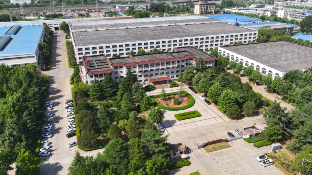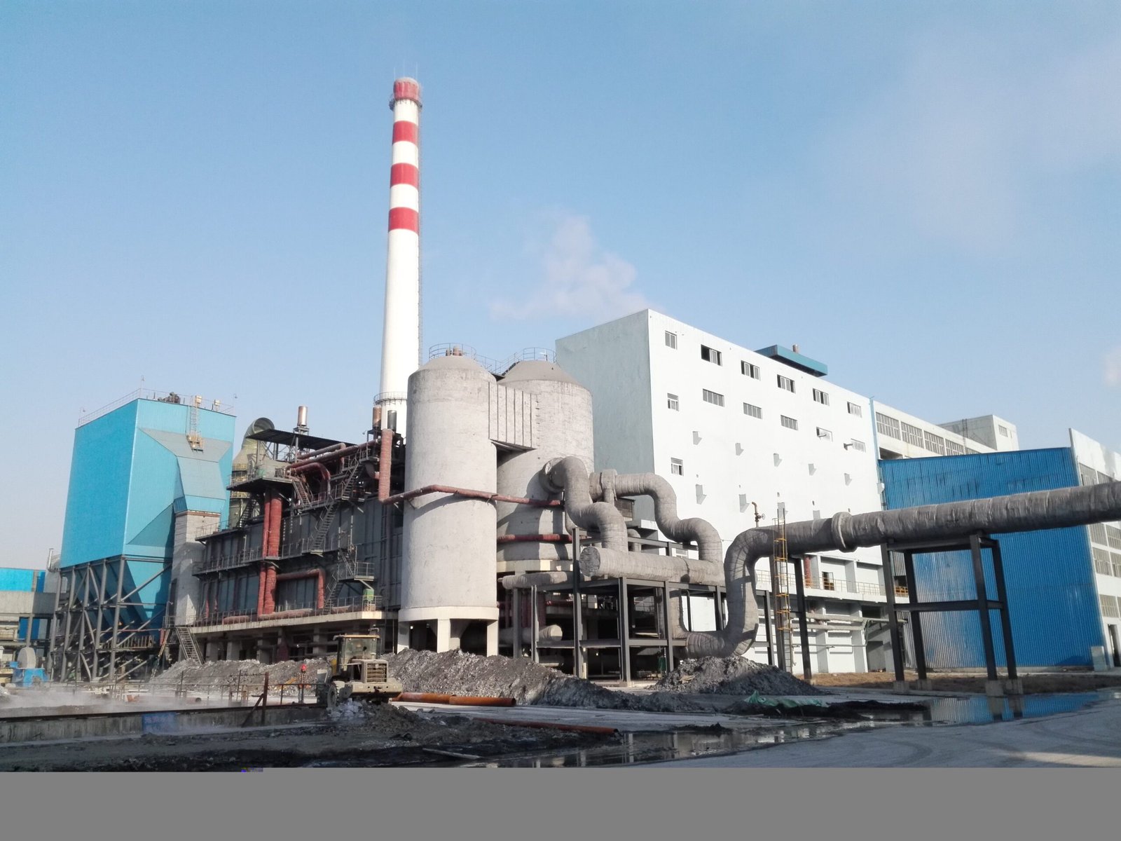
Exhaust gas leaving your process at 400–600 °C and venting straight to atmosphere is not a design choice — it is a recurring cash loss that compounds every operating hour. In cement kilns, glass furnaces, and steel reheating applications, that unrecovered enthalpy typically represents 15–30% of total fuel input, depending on process temperature and load factor. Over a year of continuous operation, that translates to fuel bills and carbon penalty costs that would have paid for the recovery system several times over. The engineering challenge is not whether to recover it, but which generation of boiler design actually captures the most of it without creating a maintenance burden that erases the savings.
The latest waste heat recovery boiler innovations include advanced finned-tube economizer modules that reduce flue gas exit temperatures to 120–150 °C, down from a conventional 180–220 °C baseline; modular skid-mounted units delivering 2–50 t/h steam at pressures up to 9.8 MPa; and predictive soot-blowing systems that sustain 85–92% recoverable heat utilization in cement and steel plant duty cycles — measurably higher than equipment designed even a decade ago.
What has changed in the last few years is not just incremental tuning. Material selection, heat transfer surface geometry, controls integration, and modular construction philosophy have all shifted enough that a WHRB specified in 2015 and one specified today are genuinely different pieces of equipment — in performance, in footprint, and in how much downtime they cause you over a ten-year operating window. The gap between getting this right and getting it approximately right shows up in your steam balance, your maintenance log, and eventually your P&L.
High-Alloy and Composite Tube Materials That Survive Aggressive Flue Gas Chemistries
Tube failures in waste heat recovery boilers almost never come from thermal overload alone. The real killers are sulfidation pitting at 400–550°C, chloride-induced stress corrosion cracking in waste-to-energy flue gas, alkali-sulfate deposit corrosion in cement kiln exhausts, and straight-up erosion from fly ash or clinker dust at velocities that would strip paint off a wall. Selecting the wrong tube material is one of those procurement mistakes that looks cheap on day one and catastrophically expensive by year two.
TP347HFG and Super304H for High-Temperature Superheater Duty
Above 550°C metal temperature — which is routine in refinery WHRB superheaters and in the high-pressure sections of steel plant heat recovery steam generators — conventional T91 creep-strength ferritic steel starts losing its oxidation resistance advantage. Its Cr content (roughly 9%) is adequate in clean gas, but in H₂S-bearing refinery off-gas or in sulfur recovery unit tail-gas streams, T91 shows measurable sulfidation attack at flue gas sulfur concentrations above about 200 ppm, especially with cyclical temperature swings.
TP347HFG and Super304H close that gap. Both are austenitic grades with fine intragranular precipitation of Nb and Cu respectively, giving oxidation resistance benchmarks roughly 30–40°C higher than standard 347 SS and substantially better than T91 in mixed oxidizing-sulfidizing atmospheres. In practical terms, you can run these grades at tube metal temperatures of 600–630°C with confidence in a reasonably well-designed HRSG superheater, whereas T91 at the same conditions in a sulfur-bearing gas stream will show measurable wall thinning within 18–24 months. The cost premium is real — expect roughly 2.5–3.5× the material cost of T91 per meter of tube — but a single unplanned superheater bundle replacement typically costs more than the entire material upgrade would have.
Super304H austenitic stainless steel provides superior oxidation resistance compared to T91 ferritic steel in sulfur-bearing flue gas environments above 550°C metal temperatureTrue
Super304H contains approximately 18% Cr plus Cu and Nb precipitates that improve both creep strength and oxidation resistance in mixed oxidizing-sulfidizing atmospheres. T91's 9% Cr content is insufficient for sustained resistance at these temperatures in high-sulfur gas streams, as confirmed by published corrosion testing data from materials suppliers including Nippon Steel and Sandvik.
Bimetallic and Clad Tubes for Waste-to-Energy and Chemical Plant Environments
Waste incineration flue gas is genuinely hostile — chlorine concentrations of 500–2,000 mg/Nm³ are not unusual depending on feedstock, and alkali chloride deposits on tube surfaces create a low-melting eutectic that accelerates corrosion at temperatures as low as 280–320°C. Running solid Alloy 625 tubes through an entire evaporator bank is cost-prohibitive for most projects. Explosion-welded and hydraulic-expanded clad tubes — carbon steel structural shell with a 1.5–3 mm Alloy 625 or Inconel 825 liner — give you most of the corrosion resistance at a fraction of the material cost, typically 40–60% less per tube than solid nickel-alloy construction depending on current nickel pricing and wall thickness.
The bond integrity matters enormously here. A poorly bonded clad tube will delaminate under thermal cycling, and once the bond fails the liner offers no protection at all. Any EPC specification for waste-to-energy WHRB duty should mandate shear bond strength testing per ASTM A264 and require 100% ultrasonic bond inspection on delivered tubes, not just mill certification review.
Ceramic Composite Coatings at High-Erosion Inlet Rows
Cement clinker cooler exhaust gas is abrasive at a level most boiler engineers underestimate until they pull the first inspection cover and find the leading inlet-row tubes looking like they were sandblasted — because they essentially were. Gas velocities above 15 m/s carrying clinker dust concentrations of 20–80 g/Nm³ will erode unprotected carbon steel tube walls at rates of 0.3–0.8 mm per year depending on particle hardness and impingement angle.
Plasma-sprayed Al₂O₃-TiO₂ ceramic coatings applied to the windward face of inlet-bank tubes reduce erosion rates by roughly 60–75% compared to bare carbon steel in well-documented cement plant installations. SiC sleeve inserts — machined ceramic collars pressed or cemented over tube OD at the first two to three tube rows — offer even better abrasion resistance and are replaceable without cutting and re-welding the tube. Coating adhesion above 700°C becomes inconsistent, so these approaches are appropriate for the cooler evaporator sections; the superheater requires the metallurgical solutions described above.
Thermal Spray Shields and Replaceable Wear Tiles at Bend Zones
Tube bends in electric arc furnace off-gas WHRB installations take disproportionate erosion damage because turbulent gas flow and inertial particle separation concentrate dust impact at the outer radius of every bend. Before purpose-designed wear protection became standard, scheduled replacement intervals of 15–20 months were typical at steel plants running high-scrap EAF operations with iron oxide-rich off-gas. Modern thermal spray erosion shields — tungsten carbide/cobalt applied by HVOF process at 0.3–0.6 mm build thickness — combined with removable ceramic tile clip-on guards at the most exposed bends have pushed realistic replacement intervals out to 4–5 years in current installations. That difference, across a medium-sized EAF recovery system, easily represents USD 200,000–400,000 in avoided maintenance costs and production downtime over a five-year campaign, depending on plant labor rates and steam output requirements.
Procurement Specification Checklist for WHRB Tube Bundles in EPC Contracts
Vague material specifications are how projects end up with substituted grades that look similar on a mill cert but perform completely differently in service. A functional EPC tube bundle specification should include at minimum:
| Specification Item | Minimum Requirement | Why It Matters |
|---|---|---|
| Material grade and standard | Full UNS designation + ASME/ASTM standard (e.g., UNS S34710 per ASTM A213) | Prevents equivalent-grade substitution with inferior product |
| Wall thickness tolerance | Per ASTM A213 (minimum wall, not average wall) | Average-wall specification allows thin spots at corrosion risk zones |
| Charpy impact testing | Full-size CVN ≥27 J at design minimum temperature | Critical for materials used in cold-climate or cyclic-duty installations |
| Third-party PMI verification | 100% portable XRF on delivered tubes, witnessed by owner’s inspector | Mill certs alone do not catch heat or grade mix-ups |
| Clad bond integrity (if applicable) | 100% UT bond scan per ASTM A264; minimum shear strength stated | Detects delamination before installation, not after first heatup |
| Surface condition | ID and OD cleanliness class per ASTM A450 | Particularly important for TP347HFG where sensitization risk must be controlled |
Third-party PMI — portable X-ray fluorescence alloy verification — sounds like a detail, but in practice, heat mix-ups between TP347 and plain 304 SS, or between T91 and T22, happen more often than the industry likes to admit. On a large WHRB bundle procurement of several hundred tubes, the cost of full PMI inspection is modest; the cost of discovering a mixed-grade bundle during a corrosion failure outage is not.
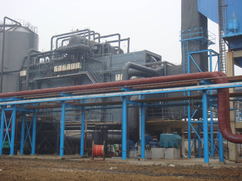
Next-Generation Heat Transfer Surface Geometries: Finned Tubes, Spiral Channels, and 3D-Printed Inserts
Heat transfer surface design is where most of the real performance gains in modern WHRBs are happening. The pressure vessel code work and material selection matter, obviously, but the geometry of the surfaces that actually touch the gas stream is what determines whether you recover 87% of available heat or 91% — and whether the unit runs six months between cleanings or six weeks.
Helical Serrated Finned Tubes: The Step Change from Solid Fins
Solid-fin tubes were the industry standard for economizer duty for decades, and they work fine in clean flue gas. The problem is that “clean” barely describes any real industrial exhaust stream. In cement and steel plant service, where you’re dealing with dust loadings of 20–60 g/Nm³ before the WHRB inlet, solid fins trap particulate in the inter-fin valleys and the convective coefficient degrades fast.
Helical serrated fins change that. With a fin pitch of roughly 4–8 fins per inch and fin height in the 12–19 mm range, the interrupted fin geometry creates periodic boundary layer disruption along the gas flow path. In economizer duty, measured convective heat transfer coefficients typically run 45 W/m²K with solid fins and jump to 65–80 W/m²K with serrated helical fins — depending heavily on gas velocity (usually 8–14 m/s in the bank), dust loading, and tube pitch. That’s not a marginal improvement. It allows a meaningful reduction in surface area for the same UA value, which on a 20 t/h skid unit can translate to a noticeably shorter heat exchanger length and lower structural steel cost.
The serrated profile also gives ash somewhere to go. The gaps in the fin allow fines to pass rather than pack, which is why self-cleaning performance is better than solid fins even before you involve any soot-blowing system.
Spiral-Wound Tube Bundles for Skid-Mounted WHRBs
Compact skid units rated 2–50 t/h at 1.0–9.8 MPa have a layout problem: you need enough heat transfer surface, good flow distribution across the gas side, and you cannot afford the bridging and channeling that plague conventional in-line or staggered tube bank arrangements when the flue gas carries sticky ash.
Spiral-wound tube bundles solve part of this. Gas flows across helically wound tubes in a continuous curved path rather than hitting discrete transverse rows. The result is more uniform velocity distribution across the bundle cross-section — in-line banks routinely show velocity maldistribution of ±25–35%, while well-designed spiral arrangements can bring that below ±12%, based on CFD validation work and field measurements from glass furnace and chemical plant installations. More uniform flow means more uniform heat extraction and fewer dead zones where ash builds up and bridges between tubes.
This matters most in glass furnace WHRBs where the gas carries condensed sulfate compounds that are genuinely sticky at temperatures between 280–450°C. Ash bridging in a staggered bank in that service can force an unplanned outage in under 400 hours. Spiral geometry doesn’t eliminate the problem, but it reduces bridging probability enough to extend cleaning intervals to something more manageable.
Additive-Manufactured Turbulator Inserts for Fire-Tube WHRBs
Large fire-tube WHRBs — the type common in chemical plant and refinery service where a single process furnace or reactor off-gas feeds one large shell — have always been limited by internal convective resistance in the fire tubes themselves. The gas-side coefficient inside a large-bore smooth fire tube is poor. Traditional approaches used helical wire inserts, which help but are difficult to remove for cleaning and corrode in aggressive gas chemistries.
AM turbulator inserts, typically printed in 316L or Alloy 625 depending on the gas composition, are now appearing in field trials. The geometry can be optimized — twisted tape, louvered vane, or more complex topologies — in ways that casting or machining simply can’t achieve economically. Field test data from several installations in sulfur recovery and coke oven gas service shows 12–18% improvement in overall heat transfer coefficient compared to smooth tubes, with shell-side pressure drop increase held below 8%. The key is the ability to tailor the insert geometry to the specific flow regime: the Reynolds number inside a large fire tube running hot gas at moderate velocity is often in transition flow territory, and AM lets you design for that specific Re range rather than using a generic off-the-shelf insert.
AM turbulator inserts achieve 12–18% overall heat transfer improvement with less than 8% increase in fire-tube pressure drop in industrial WHRB field trialsTrue
This range is consistent with published experimental and CFD literature on enhanced tube inserts in the relevant Re range (typically 5,000–30,000) for industrial fire-tube geometries; specific values depend on insert geometry, tube bore, gas velocity, and gas properties
Acoustic Soot Blowers and Rotating Brushes Paired with Extended Surface Tubes
In biomass and MSW co-processing WHRBs, sticky ash fouling has historically been the hard ceiling on how aggressive you can get with extended surface design. More surface area means more fouling area, and if your cleaning system can’t keep up, you’ve built a very efficient fouling collector.
The current practical answer is pairing acoustic soot blowers with rotating brush cleaning systems on the finned sections. Acoustic blowers — typically operating at 70–150 Hz, chosen based on tube bundle resonant frequency — work continuously at low cost and handle dry, loose ash well. Rotating brushes deal with the stuck material that acoustics alone won’t shift. The combination allows extended surface tube designs to operate in MSW service with cleaning cycles of 4–8 hours between acoustic cycles, with brush cleaning runs every 24–72 hours depending on fuel quality. Run either system alone in that service and you’ll typically find fouling limits actual heat transfer within days.
Engineering Trade-Off Matrix for Five Common Flue Gas Types
The right surface geometry is not universal. This table captures the realistic design guidance based on gas type, rather than defaulting to one geometry for everything.
| Flue Gas Source | Recommended Surface Type | Fouling Risk | Cleaning System | Draft Fan Penalty |
|---|---|---|---|---|
| Cement kiln (dry process) | Serrated helical fin, 6 fins/inch | Moderate | Sonic + steam lance | Low–moderate |
| Steel electric arc furnace | Plain or low-fin tube | High (metallic fume) | Retractable steam blower | Low |
| Glass furnace | Spiral-wound plain tube | High (sulfate sticky) | Acoustic + chemical wash | Moderate |
| Biomass / MSW co-firing | Serrated fin + acoustic | Very high | Acoustic + rotating brush | Moderate–high |
| Chemical plant / refinery off-gas | AM turbulator (fire tube) | Low–moderate | Periodic hydrojet | Very low |
Draft fan power consumption is the cost that extended surfaces impose on the system that often gets underweighted at the design stage. A heavily finned economizer section that drops exhaust gas exit temperature from 185°C down to 130°C is recovering real energy — but if it adds 15–20 mm WG of gas-side resistance, the ID fan running 8,000 hours per year absorbs that too. In most cases the heat recovery still wins, but the calculation should be done explicitly before specifying fin density, particularly in plants where electricity cost is high or the fan motor is already running near rated current.
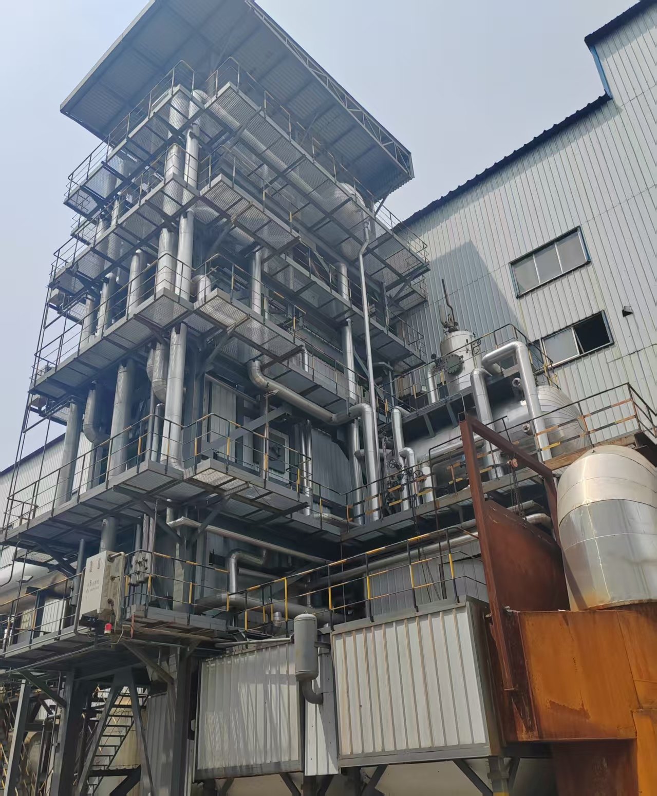
Modular and Skid-Mounted WHRB Configurations for Fast Deployment and Plant Expansions
The pressure to recover waste heat faster — and with less site disruption — has pushed modular WHRB design from a niche option into the mainstream of EPC procurement. Plant owners in Southeast Asia, the Middle East, and Sub-Saharan Africa rarely have the luxury of a clean greenfield pad, experienced local boilermakers, or a 24-month construction window. A shop-fabricated, pre-tested skid package changes the equation considerably.
Shop-Fabricated Skid Packages: What the Numbers Actually Look Like
Modular WHRB units in the 2–35 t/h steam output range are typically built as single or double-module skids. A 10 t/h saturated steam unit at 2.5 MPa, for example, usually ships on a skid footprint of roughly 3.0 m × 2.4 m × 6.5 m and weighs somewhere between 18 and 28 tonnes depending on drum size and insulation spec — both dimensions heavily influenced by whether the client specifies carbon steel or alloy tube bundles. That puts it within standard 40-foot flat-rack container parameters, which matters enormously when your destination port is Mombasa or Surabaya and heavy-lift cranes are expensive or unavailable.
Units up to about 20 t/h can usually be shipped as a single lift. Above that, the drum assembly typically travels separately and site-connects to pre-piped tube bundle modules via flanged spool pieces. Design teams who’ve done this before know to locate those flange joints carefully — you want them accessible for torquing and future inspection, not buried inside the casing stack.
Pressure-Part Sub-Assembly Strategy Cuts On-Site Welding Dramatically
The real schedule leverage in modular construction comes from eliminating field welds on pressure parts. A well-engineered modular WHRB breaks the pressure envelope into discrete sub-assemblies — steam drum, mud drum, inlet and outlet headers, and individual tube bundle modules — each hydraulically tested to code requirements at the factory before a single bolt gets tightened for shipping.
On-site, these modules connect through flanged spool pieces with pre-cut gasket faces and bolt patterns that a competent millwright crew can assemble without certified pressure welders. In practice, this approach cuts on-site welding hours by 60–75% compared with a stick-built unit of equivalent capacity. That’s not just a cost saving; in remote locations, it’s sometimes the difference between a project being executable at all.
Modular WHRB construction reduces on-site pressure-part welding by 60–75% compared with conventional stick-built erection.True
This range is consistent with published EPC benchmarking data and results from structured modular construction programs in the oil, gas, and power sectors, where flanged pressure-part connections replace field-welded joints on drums, headers, and tube bundle casings.
Parallel Multi-Module Architecture for Large Industrial Plants
A cement plant or integrated steel facility needing 80–150 t/h total WHRB capacity can’t realistically ship that as a single unit. The practical answer is a parallel multi-module train — typically four to eight identical skid modules feeding a common steam header. Each module runs independently with its own control loop, isolation valves, and blowdown system.
This architecture pays dividends during maintenance. You can take one module offline for tube cleaning or inspection while the rest of the train continues operating, avoiding the full-plant shutdown that a single large stick-built WHRB would force. The inter-module steam header design deserves careful attention: header sizing needs to account for worst-case single-module trip and the resulting pressure transient, and the control system has to handle partial-load redistribution without hunting. Usually this means a dedicated header pressure controller cascaded to individual module steam flow controllers, not a single master loop.
Stick-Built vs. Modular: Installed Cost and Schedule Reality
On a 30 MW equivalent industrial WHRB EPC project — roughly 50 t/h at moderate pressure — the installed cost difference between stick-built and modular execution typically lands in the 15–25% range in favor of modular, depending primarily on local labor rates and civil work complexity. Sites with poor soil conditions or significant platform steelwork requirements tend to show the higher end of that saving because modular skids reduce foundation loads and eliminate much of the above-grade structural steel.
Schedule compression runs 4–6 months on projects of this scale. Shop fabrication and site civil work run in parallel rather than sequentially, which is where most of that time comes from. The residual schedule risk — weather, customs clearance, port congestion — is real and shouldn’t be papered over in a project risk register.
Manufacturing Qualification for Export Projects
For clients specifying ASME Section I or Canadian CRN registration — common requirements on Middle East refinery and North American industrial projects — Taishan Group’s modular WHRB units are designed, fabricated, and third-party inspected to meet those standards, with operating pressures up to 9.8 MPa design pressure across the modular range. Units undergo full steam-blow and functional testing at the manufacturing facility before shipment, so the first time steam flows through the system on a remote site isn’t also the first functional test of the safety valve settings or the drum level control response. That matters more than it sounds on a project where the nearest spare part supplier is a three-day freight run away.
Digital Twin, AI-Driven Combustion Optimization, and Predictive Fouling Management in Modern WHRBs
Conventional WHRB maintenance has always been reactive in practice — you run the unit, watch the steam output slowly degrade, schedule a soot-blowing cycle based on elapsed hours rather than actual deposit load, and hope nothing fails before the next planned outage. That approach made sense when instrumentation was expensive and data historians were an afterthought. It doesn’t make sense anymore.
What a Working WHRB Digital Twin Actually Looks Like
A properly implemented digital twin for a waste heat recovery boiler isn’t a dashboard with pretty trend lines. It’s a physics-based thermal model — mass balance, heat transfer coefficients, flue gas composition estimates derived from upstream process signals — running in parallel with the real unit, updated continuously from 8 to 12 axial thermocouple stations distributed along the gas path, plus tube wall thermocouples at the two or three zones you know from experience are most likely to foul or corrode first. Steam drum pressure, superheat temperature, and feedwater flow complete the picture on the steam side.
The model’s job is to predict what the unit should be producing given current flue gas conditions, then flag deviations. A 3–5% drop in predicted-versus-actual heat transfer coefficient at a specific tube bank is a fouling signal. A tube wall temperature running 15–20°C above the model’s expectation at a fixed gas-side condition is either localized scale buildup on the waterside or, worse, the beginning of a dry-out problem. Either way, you want to know before the next scheduled inspection, not during it.
Predictive Fouling: From Scheduled Soot Blowing to Demand-Based Cleaning
AI fouling models trained on historical soot blower cycle logs, flue gas opacity measurements, and steam output degradation curves have shown real results in cement and steel plant applications. At a 4,500 t/day cement kiln WHRB installation, shifting from time-based to prediction-triggered soot blowing — using a model that correlated raw meal chemistry, kiln inlet gas temperature swings, and opacity sensor data — produced roughly a 22% reduction in unplanned shutdowns over an 18-month operational window. The mechanism isn’t mysterious: the model catches the fouling trend early enough that a targeted blowing cycle clears it before it bakes into a hard deposit that no soot blower can shift.
The practical limit is data quality. These models need at least 12–18 months of labeled historical data to generalize across seasonal fuel mix changes and process upsets. Plants that never logged soot blower timestamps or correlated them with opacity readings have to build that dataset first, which delays payback.
AI-based soot blower optimization demonstrably reduces unplanned WHRB shutdowns compared to fixed-interval cleaning schedules in cement kiln applications.True
Multiple cement industry case studies and vendor field reports confirm 15–25% reductions in unplanned downtime when demand-driven soot blowing replaces fixed time-interval protocols, driven by earlier fouling detection and reduced hard-deposit formation.
Permanent Ultrasonic Thickness Monitoring at Erosion Hot Spots
Permanently installed phased-array ultrasonic transducers (PAUT) at known high-erosion zones — typically the leading tube rows in the high-velocity gas entry section and any external bend locations where fly ash impinges — give you continuous wall thickness trending rather than a snapshot every outage. Cloud-based plant asset management platforms receive this data and generate corrosion rate dashboards that maintenance engineers can pull up without entering the boiler. The value isn’t just early warning; it lets you extend inspection intervals with documented justification rather than guessing.
One operational caution: PAUT sensors bonded directly to tube external surfaces in gas paths above 350°C require careful selection of both the transducer type and the coupling medium. Standard piezoelectric elements lose sensitivity fast at those temperatures. High-temperature EMAT (electromagnetic acoustic transducer) variants are worth the cost premium at those locations.
VFD Fan Control Responding to Twin-Derived Load Forecasts
Induced draft fans and recirculation fans on a WHRB are traditionally controlled by damper position — crude, energy-wasteful, and slow to respond to process swings. VFD-controlled fans responding to digital twin load forecasts rather than simple process variable feedback reduce auxiliary power consumption by roughly 8–14%, depending on how variable the upstream heat source actually is. A cement kiln running at stable throughput gives you less room to save than a steel EAF with its highly cyclic tapping schedule. The twin forecasts the next 5–15 minutes of gas flow based on upstream process state, pre-positions the fan speed, and eliminates the lag that damper systems introduce.
Integration Reality: Protocols, Retrofits, and What EPC Contracts Should Specify
OPC-UA is the right choice for structured data exchange with plant DCS and historian systems in greenfield projects — it handles the necessary security layers and data modeling without the brittleness of older Modbus TCP implementations. MQTT works well for lightweight telemetry streams to cloud platforms, particularly where bandwidth is limited or the plant is in a remote location. Modbus TCP stays relevant for retrofits where existing field devices can’t be swapped out; most WHRB digital monitoring packages support all three, but EPC contracts should explicitly specify which protocols are required rather than leaving it to default vendor selection.
ERP integration — pushing WHRB performance KPIs into maintenance work order generation and energy cost accounting — is where most projects stall. The data connection is technically simple. The organizational barrier is getting plant IT, process engineering, and maintenance to agree on data ownership and alarm response workflows before commissioning, not after.
Combined Cycle and Organic Rankine Cycle Integration to Maximize Power Recovery from Low- and Medium-Grade Waste Heat
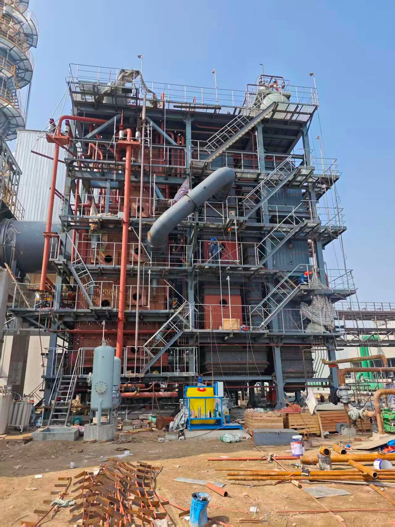
Recovering heat into steam is only half the opportunity. The other half is turning that steam — or the lower-grade enthalpy that falls below economic steam conditions — into electricity. For a cement plant, refinery, or large glass furnace already running a WHRB, adding a power generation block can shift the site from a net grid consumer to something close to self-sufficient. Whether that’s a steam turbine generator or an ORC expander depends almost entirely on the flue gas inlet temperature and the plant’s appetite for capital.
WHRB Plus Condensing Steam Turbine Generator for High-Temperature Applications
When flue gas enters the WHRB above roughly 400°C — as it does at a cement clinker cooler or a copper smelter off-gas duct — the recoverable enthalpy is high enough to generate superheated steam in the 3.5–9.8 MPa range, which a condensing steam turbine generator handles efficiently. A practical reference case: a 100 t/h clinker-cooler WHRB in a mid-sized cement plant will typically produce somewhere between 8 and 12 MWe, depending on steam conditions, condenser vacuum quality, and how aggressively the cold-end is pushed. That spread matters — the difference between 8 and 12 MW at $0.10/kWh over 8,000 operating hours is roughly $3.2 million per year. Tube fouling and clinker-cooler bypass damper settings are the two variables that most often explain why a site lands at the low end of that range rather than the high end.
ORC Integration Where Steam Economics Break Down
Below about 380°C gas inlet temperature, and certainly below 280°C, conventional steam cycles become awkward — low steam quality, wet expansion through the turbine, and condenser sizing that starts eating into the economic case. ORC systems step in here. The working fluid (R245fa is common in packaged units up to roughly 5 MWe; pentane and toluene become attractive above that for higher turbine inlet temperatures, though they bring flammability and seal-material implications that need serious attention) evaporates at lower temperatures than water, runs through a hermetically sealed turbine-expander, and condenses against available cooling. Net electrical efficiency for an ORC coupled to a WHRB economizer section with gas inlet temperatures in the 200–380°C band realistically falls between 12 and 18%, with the upper end requiring toluene or a similar high-boiling fluid and good cooling water temperatures. Don’t let vendors quote you 20%+ without showing the full heat balance — parasitic loads on the cooling circuit often eat 2–4 percentage points that disappear in the headline number.
Two-Pressure-Level WHRB: Serving Both Process and Power Simultaneously
A two-drum WHRB — HP drum at around 4.0 MPa feeding a back-pressure or condensing STG, LP drum at 0.5 MPa bleeding extraction steam into the plant’s process heat network — is the configuration that, in my experience, gives the best overall thermal utilization on industrial sites with both power and process steam demand. The HP section extracts work from the high-enthalpy portion of the gas stream; the LP section captures what’s left, which would otherwise go to the economizer or be exhausted. Heat balance modeling for a 50 MW thermal input typically shows 6–10% efficiency uplift over a single-pressure design, depending on process steam load profile and how flat or variable that load runs seasonally.
Economic Comparison Across Configurations
The decision table below reflects realistic capital ranges and IRR for a 50 MW thermal input site at two electricity tariff levels. All figures assume approximately 8,000 operating hours per year and exclude land and permitting costs, which vary too much by region to generalize.
| Configuration | Approx. Capital Cost (USD) | IRR at $0.08/kWh | IRR at $0.12/kWh |
|---|---|---|
| Standalone WHRB, process steam only | $1.8–3.5 M | N/A (cost avoidance) | N/A |
| WHRB + ORC expander | $4.5–8.0 M | 9–14% | 15–22% |
| WHRB + condensing STG | $6.0–12.0 M | 11–17% | 18–26% |
| Two-pressure WHRB + STG + process steam | $8.0–15.0 M | 13–19% | 20–28% |
IRR ranges depend on steam pressure, cooling water cost, O&M staffing model, and whether power is exported to the grid or consumed internally. Internal consumption almost always yields better returns because it avoids grid transmission charges and demand tariffs.
ORC systems integrated with low-temperature WHRB sections operating on flue gas inlet temperatures of 200–380°C achieve net electrical efficiencies of 12–18% depending on working fluid selection and cooling conditions.True
Published data from ORC manufacturers (Turboden, Ormat, Exergy) and peer-reviewed studies confirm this efficiency range for industrial ORC installations in this temperature band, with toluene and pentane systems at the upper end and R245fa systems typically at the lower end due to lower turbine inlet temperatures.
EPC Project Structuring: Why a Single Integrated Package Reduces Risk
Interface risk is the thing that quietly kills power island projects. When the WHRB supplier, the turbine supplier, the condenser fabricator, and the electrical contractor each hold separate contracts, warranty disputes over underperformance become protracted and expensive — and the plant owner is usually left holding the gap while suppliers point at each other. Taishan Group’s approach on overseas integrated packages is to supply the WHRB, steam turbine, surface condenser, cooling tower, feedwater system, and electrical balance of plant under a single EPC envelope. That means one performance guarantee, one interface owner, and one commissioning team. For a plant owner in Southeast Asia or the Middle East evaluating a first-of-type power island without deep in-house power engineering resources, that structure is often worth more than shaving a few percent off the equipment price.
Integrated Emission Control within WHRB Systems: SCR, Dry Sorbent Injection, and Acid Dew-Point Management
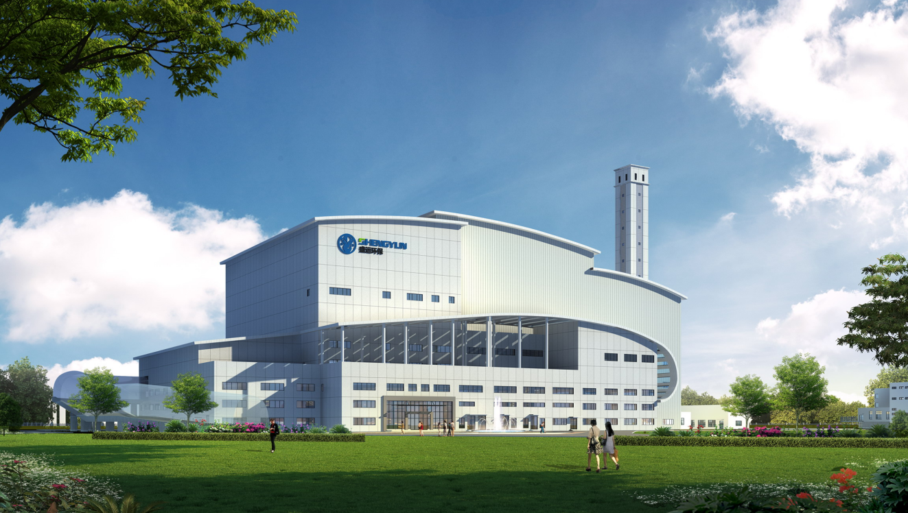
The old approach — recover the heat first, then treat the flue gas somewhere downstream in a separate building with its own foundations, ducting, and controls — is increasingly hard to justify on cost or footprint grounds. What’s changed in the last several years is that WHRB manufacturers are engineering the emission control functions directly into or immediately downstream of the boiler convection pass, so the whole stack becomes one contracted scope. For EPC buyers in particular, this collapses the vendor interface problem that historically produced so many finger-pointing disputes during commissioning.
Embedding SCR in the Convection Pass
The temperature window for SCR catalyst activity is non-negotiable, and getting it right is largely a heat transfer sequencing problem. Vanadium-pentoxide catalyst — still the dominant choice in cement and steel WHRB applications — requires a gas temperature of roughly 300–420°C to achieve NOx conversion efficiencies in the 80–95% range without catalyst poisoning or ammonia slip. Zeolite-based low-temperature SCR can operate between about 180–280°C, which opens up placement options further down the convection bank, useful when the process exhaust enters the WHRB already below 450°C.
The ammonia injection grid (AIG) design is where you see the biggest variation in practice. A poorly distributed NH₃ spray produces stratified ammonia concentrations that show up as slip even when the average is within permit — something a stack CEMS will catch, but only after regulatory exposure has already occurred. Modern AIG designs use multi-zone control with individual mass-flow controllers per lance row, tuned to the velocity profile mapped during CFD modeling. Some suppliers are integrating laser-based in-duct NH₃ concentration measurement directly at the SCR inlet to close that loop in real time. It adds cost, but on a 200,000 Nm³/h cement kiln gas stream, the alternative is carrying excess reagent as an insurance policy, and that has its own compliance ceiling.
Dry Sorbent Injection for SO₂ and HCl
Hydrated lime (Ca(OH)₂) and sodium bicarbonate (NaHCO₃) are the two workhorses for DSI upstream of a fabric filter. Sodium bicarbonate is significantly more reactive — especially below 200°C — and achieves SO₂ removal in the 85–92% range at stoichiometric ratios of roughly 1.5–2.0 mol/mol depending on contact time and gas humidity. Hydrated lime typically delivers 70–85% removal at similar conditions and costs considerably less per tonne, so for continuous high-sulfur duty it often wins on lifecycle economics even with higher consumption rates. A rough benchmark for lime: expect 1.2–1.8 kg Ca(OH)₂ per kg SO₂ removed in a well-designed duct injection system with adequate residence time (usually at least 1–2 seconds before the baghouse inlet). HCl removal tracks similarly but tends to respond better to lime than sodium bicarbonate at temperatures above 180°C — worth knowing if the WHRB is handling municipal solid waste or industrial hazardous waste flue gas.
Sodium bicarbonate DSI achieves higher SO₂ and HCl removal efficiency than hydrated lime at equivalent stoichiometric ratios and temperatures below 200°C.True
This is well-established in industrial air pollution control literature and consistent with activation chemistry: sodium bicarbonate decomposes to Na₂CO₃ above approximately 60°C, presenting a highly porous reactive surface, giving it a kinetic advantage over Ca(OH)₂ at lower temperatures and shorter contact times.
Activated Carbon Injection in MSW and Hazardous Waste WHRBs
For municipal solid waste incinerator and hazardous waste WHRB systems, dioxin and furan suppression is non-negotiable under IED, MACT, and equivalent national regulations. Activated carbon (AC) injection — typically powdered lignite coke or bituminous AC — targets these trace organics plus mercury and other heavy metals by adsorption before the downstream baghouse captures the loaded carbon dust.
Injection point selection matters more than most operators appreciate. The AC needs to be introduced at gas temperatures below about 200°C to avoid thermal desorption of the already-adsorbed compounds — inject too early in the gas path and you’re wasting sorbent and potentially re-volatilizing captured species. Contact time between injection and filter inlet should be 3 seconds at minimum; 5–8 seconds is more reliable for low-concentration dioxin targets below 0.1 ng TEQ/Nm³. Baghouse design has to account for the increased dust cake permeability when AC is mixed into the cake — pulse-jet filter bags need to be sized with this in mind, and some plants run dedicated AC compartments within the filter housing to facilitate separate disposal of the carbon-laden fraction as hazardous waste, which it legally is.
Acid Dew-Point Management with Glass-Ceramic Economizers
The conventional answer to H₂SO₄ condensation risk in low-temperature economizers was simple: keep the flue gas outlet above 160–180°C and accept the loss. A 20°C safety margin above the measured or estimated sulfuric acid dew point was considered prudent. The problem is that this “safe” exit temperature is where a meaningful chunk of recoverable energy sits — the difference between exiting at 180°C and exiting at 130°C can represent 8–12% additional heat capture depending on gas flow and moisture content.
Glass-ceramic tube coatings and, in some recent designs, solid glass-ceramic tube segments (used in the coldest economizer rows) tolerate H₂SO₄ condensation at temperatures below 130°C without the pitting corrosion that destroys carbon steel or even enamel-coated steel over a 2–3 year operating cycle. Enamel tube coatings have been used for years in the sulfuric acid industry and for air preheaters; what’s newer is the application of these materials in WHRB economizer bundles designed as drop-in assemblies with standard header connections, so the rest of the pressure part remains conventional. In practice the design still requires careful attention to draining — condensate pockets are corrosive to anything they contact — but the operational envelope is genuinely extended.
Compliance Mapping Across Multiple Regulatory Frameworks
For overseas project owners trying to simultaneously satisfy EU IED limits, US EPA 40 CFR Part 63 MACT standards, and World Bank EHS Guidelines (often a lender requirement on project-financed plants), the integrated WHRB emission control approach has one underappreciated advantage: a single equipment contract with unified performance guarantees. When the SCR, DSI system, AC injection, and baghouse are all under one supplier’s scope, stack test failures don’t trigger the interminable blame allocation between the boiler supplier, the APC contractor, and the reagent vendor that plagues split-scope projects.
The regulatory parameters worth checking up front: IED for MSW incineration sets NOx at ≤200 mg/Nm³ (11% O₂ reference), SO₂ at ≤50 mg/Nm³, HCl at ≤10 mg/Nm³, and dioxins at ≤0.1 ng TEQ/Nm³ — all achievable with the integrated technologies described above, but only with a system designed to those targets from the start, not retrofitted at the stack test stage.
Performance Testing, Acceptance Criteria, and Quality Assurance Standards for WHRB Procurement
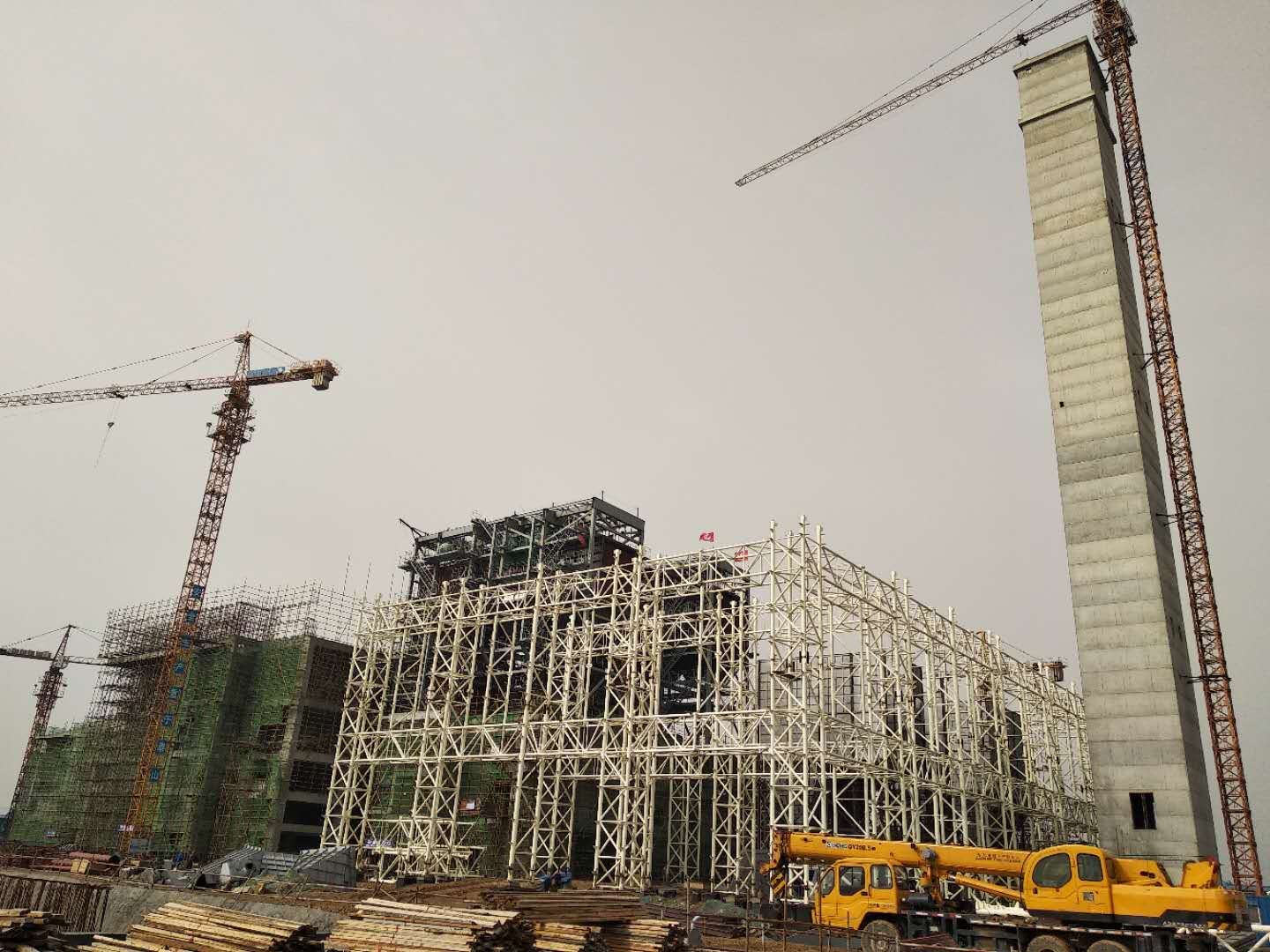
Specifying a WHRB is one thing. Getting a unit that actually performs to that specification — at startup, and two years later — is a different problem entirely. Commercial disputes over waste heat boiler performance are surprisingly common, and in my experience they almost always trace back to vague guarantee parameters, untested assumptions about flue gas composition, or FAT protocols that looked rigorous on paper but left critical measurements unverified before shipment.
Defining the Performance Guarantee Parameters
Before any PO is signed, the performance guarantee table needs to pin down at minimum: steam output in t/h, operating steam pressure and temperature, flue gas exit temperature at the boiler outlet (not the stack), boiler thermal efficiency expressed as heat absorbed divided by heat available in the inlet gas stream, and auxiliary power consumption for fans, sootblowers, and controls.
Tolerance bands matter enormously here. Industry practice typically accepts ±2% on steam output and thermal efficiency for units in stable industrial service, widening to ±5% where inlet gas conditions are variable — cement kiln WHRBs during raw mix transitions, for example, or glass furnace WHRBs during pull-rate changes. Flue gas exit temperature guarantees usually carry an absolute tolerance of ±10–15°C, and that tolerance has to be referenced to a specific guaranteed inlet gas flow and temperature, not a nominal design point. If the tolerance isn’t tied to the inlet condition, the guarantee is essentially unenforceable.
A ±5% tolerance on WHRB steam output is standard practice for variable-load flue gas sources such as cement kilns.True
Cement kiln gas flow and temperature fluctuate with raw mix feed rate, fuel type, and bypass events; ±5% on steam output is a well-accepted commercial tolerance in EPC contracts for such applications, as reflected in typical WHRB procurement specifications from major cement EPC contractors.
Applicable Standards and Code Compliance
Pressure part design should reference ASME Section I for fired and waste heat boiler applications where steam generation is involved, or ASME Section VIII Div.1 for unfired pressure vessels — and the distinction matters because inspection, stamping, and documentation requirements differ between the two. European projects require PED 2014/68/EU conformity, usually paired with EN 12952 for water-tube boilers. EN 12952 has more prescriptive requirements around water quality, operational safety systems, and documentation than many buyers realize.
For projects destined for China or with Chinese-manufactured pressure parts, GB/T 18613 addresses motor efficiency rather than boiler construction — the relevant Chinese standard for industrial boilers is GB/T 16507 (water-tube boilers). Make sure your procurement spec doesn’t conflate these. When a Chinese WHRB manufacturer says their unit meets “GB standards,” ask specifically which standard applies to which pressure boundary component.
Factory Acceptance Test Protocol
The FAT should be treated as a contract milestone, not a formality. Hydraulic pressure testing at 1.5× design pressure — held for a duration specified by the applicable code, typically 30 minutes minimum under ASME — must be witnessed by either the client’s inspector or an approved third party like TÜV, Bureau Veritas, or Lloyd’s Register. NDE requirements for longitudinal seams should specify radiographic testing (RT) or time-of-flight diffraction (TOFD); magnetic particle testing (MT) is appropriate for nozzle welds and fillet welds where RT geometry is impractical.
Dimensional inspection should cover tube bundle spacing, header nozzle locations, and overall module envelope against the certified drawing — dimensional errors found at site are expensive to remedy. If the unit includes sootblower penetrations or observation ports, verify those nozzle orientations before shipment. Witnessed steam-blow cleanliness verification, where applicable, confirms internal cleanliness to a defined target (typically a polished target plate acceptance criterion per ASME or project-specific spec).
Field Performance Test Methodology
The FPT should follow ASME PTC 4 or an agreed equivalent — EN 12952-15 is the European analog and produces comparable results when measurement methods are consistent. Measurement points for gas temperature, flow, and composition must be defined in the contract, not left to the commissioning team to determine on site. Typically this means grid-averaged temperature measurements across the duct cross-section at the boiler inlet and outlet, with a minimum of four traverse points per axis on larger ducts. Gas flow measurement by pitot traverse or calibrated flow elements should be calibrated against a reference instrument within 6 months of the test date.
Steady-state duration for the FPT should be a minimum of 4 continuous hours at the guaranteed operating condition, with no more than ±3% drift in inlet gas temperature or flow during the test window. Shorter tests introduce enough transient error to make efficiency calculations meaningless. Steam purity testing — typically conductivity and sodium content in the steam sample — should run concurrently.
Documentation Package for Overseas Shipments
A complete documentation package for an exported WHRB typically includes: material test reports (MTRs) traceable to each pressure-bearing component by heat number, weld maps with welder qualification records, NDE reports for every inspected seam, ASME U-stamp data report or equivalent national pressure vessel certificate, hydraulic test certificate, and the third-party inspection agency’s final release note. Some jurisdictions — Indonesia, Vietnam, and several Middle Eastern countries among them — require additional local authority approval before the unit can be legally operated, so build that into your project schedule rather than discovering it at customs clearance.
Buyers who skip or abbreviate any of this documentation often find themselves unable to register the boiler with local authorities, or facing a lengthy re-inspection at site. That typically costs more in schedule delay than the documentation process ever would have.
Frequently Asked Questions About Waste Heat Recovery Boiler Innovations
These questions come up repeatedly in project discussions, pre-bid meetings, and procurement reviews. The answers below cut through the usual generalizations.
What is the minimum flue gas temperature for economically viable heat recovery?
For conventional steam generation, the practical floor is roughly 250–300°C — below that, the steam pressure you can produce starts looking marginal against the capital cost of the boiler, and the economics rarely pencil out unless your steam demand is captive and your fuel cost is high. Flow rate matters as much as temperature, though. A 270°C stream at 200,000 Nm³/h is a very different proposition from the same temperature at 20,000 Nm³/h.
ORC-based systems shift that floor downward. Organic Rankine Cycle expanders working with low-boiling-point working fluids can extract useful power from gas streams in the 150–180°C range, provided the volumetric flow is substantial — typically above 30,000–50,000 Nm³/h to justify the ORC capital. In practice, the breakeven payback on ORC at those low temperatures runs 4–7 years depending on local electricity tariffs, which is acceptable in some markets and borderline in others.
How does a WHRB differ from an HRSG?
The term gets misused constantly, including in tender documents, which causes real problems downstream. An HRSG — heat recovery steam generator — is technically a subset of the broader WHRB family, but it’s specifically engineered for gas turbine exhaust: clean combustion gas, predictable temperature profiles, relatively tight fouling loads, and gas velocities that allow close tube pitching.
Industrial WHRBs behind cement kilns, electric arc furnaces, or sulfur recovery units are a completely different engineering challenge. The gas carries alkali dust, SO₂, HCl, sticky particulate, and sometimes heavy metal vapors. That demands wider gas lane spacing (typically 150–300 mm between tube rows versus 80–120 mm in an HRSG), active soot blowing, erosion-resistant leading-edge shields, and tube metallurgy selected for the specific chemical attack profile. Specifying an HRSG for a dirty industrial gas stream is one of the faster ways to destroy a tube bundle.
Industrial WHRBs handling particle-laden or chemically aggressive flue gases require wider tube lane spacing and erosion protection measures that are not standard in gas turbine HRSGs.True
Gas turbine HRSG designs assume relatively clean exhaust and use close tube pitching for compactness. Cement kiln, EAF, or SRU gases carry entrained particulate and corrosive species that cause rapid erosion and fouling at HRSG-style pitching, necessitating design modifications including wider lanes, soot blowers, and hardened tube surfaces.
Can one WHRB recover heat from multiple exhaust streams at once?
Yes, and it’s done fairly often in facilities where two or more process units share a common steam header. Multi-pass common-header configurations and parallel duct manifolds can combine two to four source streams into a single boiler or a closely coupled boiler bank, with individual isolation dampers on each inlet duct. This allows one kiln to be down for maintenance while the other continues feeding the WHRB — operationally important when the steam goes to a turbine generator that you’d rather not trip.
The engineering complication is managing the different gas temperatures and flow rates from each source, particularly if they swing independently. The control system needs to handle that asymmetry without letting cold gas from one branch drag condensation into a section of tube bundle seeing wet flue gas below its acid dewpoint.
What steam conditions do cement plant WHRBs typically produce?
Cement plants operate two distinct WHRB positions with different duty profiles. Clinker cooler WHRBs handle higher gas temperatures — roughly 350–450°C at the cooler vent — and typically produce steam at 1.6–4.0 MPa, either saturated or lightly superheated depending on whether the plant is targeting power generation or process steam. Preheater exit WHRBs sit at the back end of the suspension preheater tower where exit gas temperatures run more like 280–360°C, producing steam at 1.0–2.5 MPa. Running both in a combined configuration and feeding a back-pressure or condensing steam turbine is the standard arrangement for cement plant WHR power projects — realistically 6–12 kWh of electrical output per tonne of clinker, depending on kiln type, capacity, and how aggressively the heat surface is sized.
How long from order to commissioning for a modular WHRB?
For skid-mounted units up to around 20 t/h steam output, manufacturing lead time in a reasonably equipped boiler fabrication facility runs 16–22 weeks — pressure parts, structural steel, refractory, and factory assembly included. Field erection and commissioning adds 4–8 weeks, and that range depends heavily on site readiness: foundation quality, utility connections, and whether the process side is ready to accept steam. Total schedule from purchase order to first steam is realistically 5–7 months for a well-defined project. Larger custom units behind big cement or steel plant applications can run 10–14 months, sometimes longer if the pressure vessel inspection body has a queue.
What maintenance innovations are cutting WHRB operating costs?
Online phased-array ultrasonic thickness (PAUT) monitoring is probably the most impactful single development for tube life management — it allows wall thickness trending on high-wear zones without taking the boiler offline, which means you replace tubes based on actual remaining life rather than a conservative fixed schedule. AI-optimized soot blower sequencing, covered in an earlier section, reduces steam consumption and prevents localized erosion from over-blowing. Replaceable erosion shields on the leading tube rows in high-velocity zones — particularly in cement cooler applications — can be swapped during a planned outage rather than pulling tube sections. Together, these approaches can realistically reduce unplanned downtime by 25–35% and push tube bundle service intervals past 80,000 operating hours in reasonably well-run plants. The caveat is that “well-run” does a lot of work in that sentence; plants that skip biannual cleaning and ignore soot blower faults will see much shorter intervals regardless of what the design specification says.
Does Taishan Group supply complete WHRB EPC packages for international projects?
Yes. Taishan Group delivers full EPC scope for industrial WHRB projects internationally — process design and heat balance, pressure-part manufacturing (boiler drums, headers, tube bundles, economizers), auxiliary equipment supply (soot blowers, dampers, expansion joints, induced draft fans), civil and structural works, electrical and instrumentation packages, DCS integration, commissioning, and operator training. For procurement teams evaluating EPC contractors, the relevant questions to ask any supplier are whether the pressure-part manufacturing is in-house or subcontracted, what third-party inspection body they work with for ASME or PED compliance, and whether their commissioning team has hands-on experience with the specific gas chemistry your process generates. References from similar duty applications matter more than general capacity claims.
References
Waste Heat Recovery Basics — U.S. Department of Energy
Finding Efficiencies in Process Heat — U.S. Department of Energy
Process Heating Systems — U.S. Department of Energy
CHP Technologies — U.S. Environmental Protection Agency
Synergistic Deep Flue Gas Heat Recovery Using Corrosion-Resistant Wall-Type Condensing Heat Exchangers Coupled with Absorption Heat Pumps — Energy, Elsevier, 2026
MP-PIC Study of Flue Gas Heat Exchange and Particle Settling Pattern in Industrial-Scale Waste Heat Recovery Furnace — Chemical Engineering Journal, Elsevier, 2025
Digital Twin Development of a Full-Scale Industrial Heat Pump — Applied Thermal Engineering, Elsevier, 2025
Flue Gas-Dust Two-Phase Heat Transfer Characteristics and Corrosion Behavior in Industrial-Scale Waste Heat Boilers — Energy, Elsevier, 2024
Ash Fouling Characteristic Analysis and Prediction for Pillow Plate Heat Exchanger in Waste Heat Recovery Based on Attentive-Feature Decision Algorithm — Fuel, Elsevier, 2024
Development of an Integrated Online Deposition and Corrosion Monitoring System in a Full-Scale Solid Waste CFB Boiler — Waste Management, Elsevier, 2024