An industrial boiler P&ID (Piping and Instrumentation Diagram) is a critical engineering document connecting process flow, equipment configuration, piping systems, instrumentation, control functions, and project interfaces. Reviewing it properly before procurement and installation helps identify engineering omissions and inconsistencies before they affect equipment supply, construction, or commissioning.
A drawing may appear complete while still containing missing process connections, inconsistent equipment tags, unclear battery limits, or discrepancies between instrumentation and control documents. If these issues remain unresolved, they can lead to procurement clarifications, design revisions, installation delays, and additional project costs.
A systematic industrial boiler P&ID review should therefore examine both the drawing itself and its consistency with the supporting engineering documentation. This guide explains how EPC engineers, boiler buyers, and plant owners can review a P&ID at the pre-procurement and pre-installation stages, identify common engineering red flags, and determine whether the drawing is ready for the next project stage.
1. Define the P&ID Review Stage and Scope
The review criteria should reflect the maturity of the drawing and the project stage.
Pre-Procurement P&ID Review
Before a boiler purchase is finalized, the supplier may provide a preliminary P&ID or vendor proposal drawing. At this stage, the review should focus on the proposed process concept and major technical requirements.
Key checks include:
- Whether the proposed process flow matches the required boiler duty.
- Whether major equipment and auxiliary systems are represented.
- Whether fuel, feedwater, steam, hot-water, and flue-gas interfaces are identified as applicable.
- Whether essential instrumentation and control requirements are addressed.
- Whether the supplier’s scope of supply and battery limits are sufficiently clear.
- Whether the proposed configuration is consistent with the project specification.
The objective is to identify technical omissions or ambiguities that could affect the procurement decision or require clarification before contract finalization.
Pre-Installation or Construction Review
Before installation, the review should focus on the latest approved P&ID and its consistency with the construction documentation.
Check:
- Equipment tags and identification.
- Line numbers and service descriptions.
- Valve and instrument identification.
- Equipment and piping connections.
- Supplier, EPC, and owner interfaces.
- Control and instrumentation documentation.
- Revision history and approved design changes.
At this stage, the P&ID should provide a sufficiently clear engineering reference for the applicable procurement, fabrication, construction, and installation activities.
A preliminary vendor drawing should not be judged by exactly the same criteria as an approved construction-stage drawing. The review scope must reflect the intended purpose and approval status of each document.
Important: A P&ID review does not replace detailed engineering calculations, mechanical design verification, code compliance assessments, HAZOP, control-system validation, or site safety assessments where these are required by the project.
2. Prepare the Documents Required for a Boiler P&ID Review
A P&ID should never be reviewed in isolation. Its technical information must be cross-checked against the documents that define the boiler’s design basis, equipment configuration, and project interfaces.
Before starting the review, collect the applicable documents, which may include:
- Boiler technical specification.
- Boiler datasheet.
- Equipment list.
- Line list.
- Instrument list.
- General arrangement (GA) drawing.
- Process flow diagram (PFD), where applicable.
- Control philosophy.
- Fuel specification.
- Utility and battery-limit data.
- Scope-of-supply documentation.
- Applicable codes and project specifications.
The following table provides a practical document cross-reference framework.
| Supporting Document | Key Information to Verify |
|---|---|
| Boiler Datasheet | Capacity, pressure, temperature, design conditions |
| Equipment List | Equipment tags, types, and quantities |
| Line List | Line numbers, services, sizes, and design conditions |
| Instrument List | Instrument tags and measurement functions |
| GA Drawing | Equipment arrangement and connection locations |
| Control Philosophy | Control functions, alarms, and relevant interlocks |
| Scope of Supply | Supplier responsibilities and battery limits |
| Project Specification | Applicable technical and regulatory requirements |
The reviewer should also confirm the drawing number, revision, issue date, approval status, project reference, and design basis.
For procurement teams, the Industrial Boiler RFQ and Tender Documents Guide provides additional context on the technical documentation required during the purchasing process.
The objective here is not to repeat the datasheet review process, but to establish a reliable reference against which the P&ID can be checked.
3. Trace the Main Boiler Process Flow
The first technical step is to follow the process through the boiler system.
The central question is:
Can the process be traced logically from each relevant inlet to its corresponding outlet, including the necessary auxiliary connections?
The review should follow the actual boiler configuration rather than applying one generic arrangement to every boiler type.
Feedwater and Steam or Hot-Water Flow
For a steam boiler, trace the water and steam path from the feedwater inlet to the main steam outlet.
Depending on the boiler design, this may involve:
- Feedwater inlet and control arrangement.
- Feedwater pump connections.
- Economizer.
- Boiler or evaporating section.
- Steam drum, where applicable.
- Superheater, where applicable.
- Main steam outlet.
- Relevant vents, drains, and auxiliary connections.
Check whether the connections and major equipment shown on the P&ID agree with the boiler datasheet and equipment list.
For hot-water boilers, follow the supply and return circuits instead. Pay attention to the circulation arrangement, external heating-network connections, and relevant expansion or pressurization interfaces where applicable.
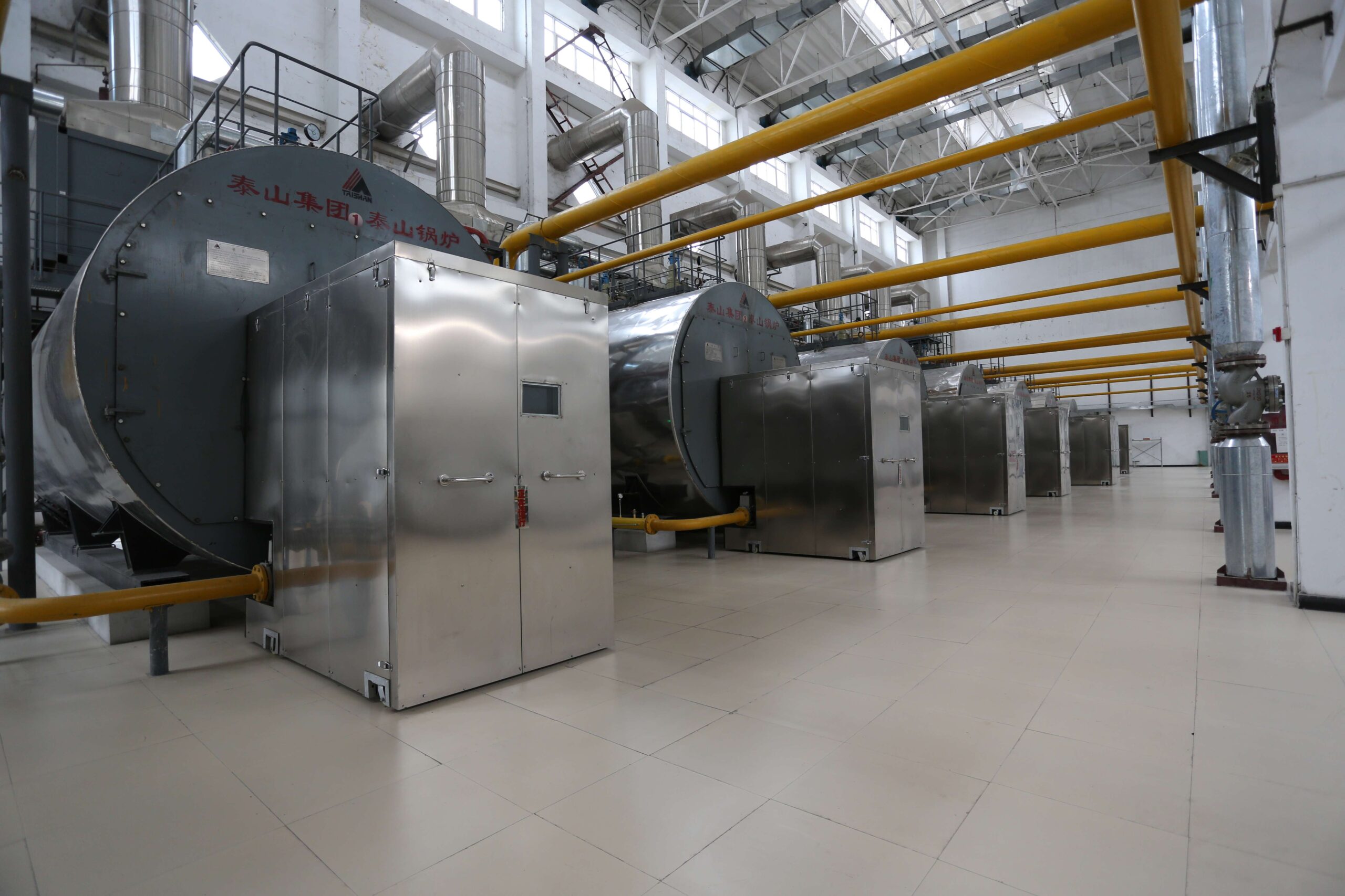
Different boiler configurations require different review criteria. For example, a coal-fired CFB hot-water boiler and a packaged gas-fired steam boiler should not be assessed using an identical process checklist.
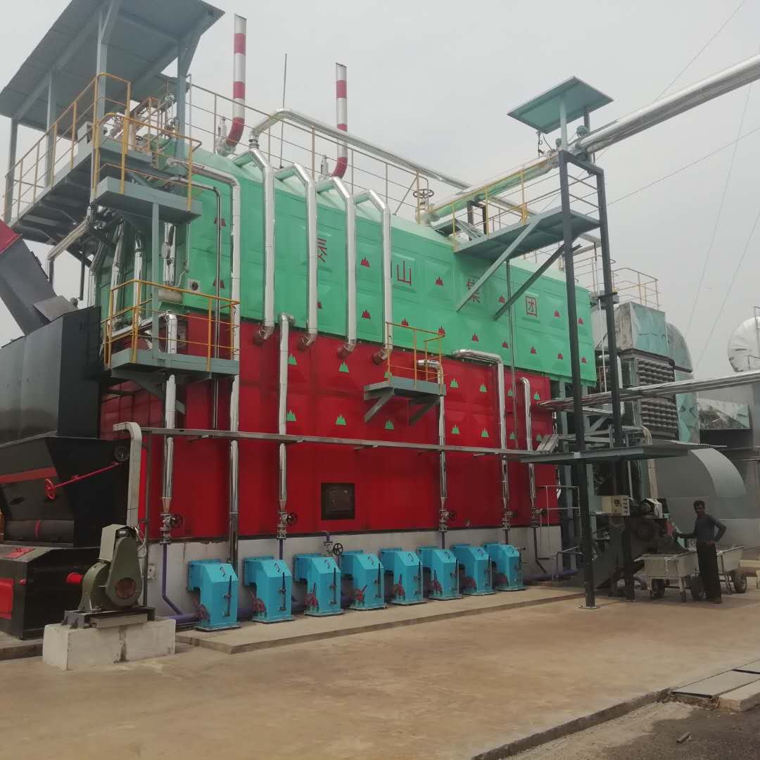
Taishan Group’s published project portfolio includes two 116 MW coal-fired CFB hot-water boilers for the Aksu Sunshine Thermal Company heating project. This illustrates the type of large-scale hot-water boiler configuration that requires its own process and auxiliary-system review basis. The published project information does not disclose the detailed P&ID, so no specific valve or instrumentation arrangement should be inferred from the case.
Fuel and Combustion Flow
Next, trace the fuel and combustion systems.
For coal-fired and biomass-fired boilers, review the applicable interfaces involving:
- Fuel feeding and conveying.
- Combustion system.
- Primary and secondary air.
- Furnace connections.
- Ash-handling systems where applicable.
- Associated auxiliary equipment.
For oil- and gas-fired boilers, the review may focus on:
- Fuel supply connections.
- Isolation and regulating equipment.
- Burner interfaces.
- Combustion-air supply.
- Relevant fuel and combustion safety interfaces.
The required arrangement depends on the fuel characteristics, boiler design, applicable codes, and project specifications.
Flue-Gas and Auxiliary Connections
Trace the flue-gas path from the furnace toward the stack or downstream process.
Depending on the boiler configuration, the system may include:
- Furnace outlet.
- Heat-transfer surfaces.
- Economizer or air-preheater connections.
- Dust collection equipment.
- Induced-draft fan.
- Flue-gas ducting.
- Stack connection.
Check whether the major equipment and connections correspond with the equipment list and GA drawing.
For example, if the equipment list includes an induced-draft fan or downstream gas-cleaning equipment but the P&ID does not clearly represent the corresponding process connection, the discrepancy should be recorded.
Blowdown, Drain, and Vent Paths
Review the water-side auxiliary connections where applicable, including:
- Continuous blowdown.
- Intermittent or bottom blowdown.
- Equipment drains.
- Vents.
- Sampling connections.
- Discharge and collection interfaces.
The purpose is to confirm that the required functions are represented and consistent with the design basis, rather than to impose a universal valve arrangement.
4. Check Equipment, Piping, Valves, and Instrumentation
After verifying the process flow, examine the individual elements represented on the drawing.
The main question is:
Are the required equipment, piping, valves, and instruments correctly identified and consistent with the supporting engineering documents?
Equipment Tags and Major Equipment
Compare the P&ID with the equipment list.
Check:
- Equipment tag and description.
- Equipment type and quantity.
- Duty/standby arrangement where applicable.
- Inlet and outlet connections.
- Consistency with the GA drawing.
An equipment tag mismatch may create problems in procurement records, datasheets, spare-parts documentation, and commissioning records.
Piping and Line Identification
For significant process lines, verify:
- Line number.
- Service or process medium.
- Flow direction.
- Nominal size where specified.
- Connection points.
- Battery-limit location.
- Consistency with the line list.
Pay particular attention to piping that crosses the boiler supplier’s battery limits. The connection and associated responsibilities should be clearly identified.
Isolation, Drain, Vent, and Bypass Arrangements
Review whether the P&ID represents the isolation and auxiliary functions required for the relevant services.
These may include:
- Isolation valves.
- Drain connections.
- Vent connections.
- Bypass arrangements.
- Maintenance isolation.
- Relevant pressure-relief or depressurization provisions.
Not every line requires the same combination of valves. The correct arrangement depends on the service, operating conditions, equipment design, applicable codes, and project requirements.
Instrumentation
Compare the P&ID with the instrument list.
Typical instrumentation categories include:
- Pressure measurement.
- Temperature measurement.
- Flow measurement.
- Level measurement.
- Control valves.
- Local indicators and transmitters.
- Alarm-related instruments.
- Relevant shutdown or protection signals.
Check whether each important instrument has a clear tag, measurement function, and corresponding reference in the supporting documentation.
For example, a pressure transmitter shown on the P&ID but missing from the instrument list should be flagged for clarification. The same applies when an instrument appears in the instrument list but has no identifiable location or function on the drawing.
5. Review Safety, Alarms, and Control Interfaces
Safety and control functions require particular attention because a P&ID may show their engineering interfaces without containing the complete control logic.
Pressure and Level Protection
Depending on the boiler type and design, review the representation of relevant:
- Pressure monitoring.
- Pressure protection.
- Water-level monitoring.
- Safety or relief devices.
- Alarm functions.
- Shutdown interfaces.
The applicable code and project specification should determine the required protection.
For power boilers within its scope, ASME Boiler and Pressure Vessel Code Section I establishes requirements for the construction of power boilers. The applicable edition should be identified through the project contract and governing code requirements.
Official reference: ASME Boiler and Pressure Vessel Code.
Fuel and Combustion Safety Interfaces
For applicable combustion systems, review whether the P&ID correctly represents the safety-related interfaces required by the design and control philosophy.
These may include:
- Fuel isolation.
- Combustion-air permissives.
- Flame-related signals.
- Relevant alarms.
- Fuel shutdown interfaces.
NFPA 85 — Boiler and Combustion Systems Hazards Code is an important reference for applicable boiler and combustion-system projects. Its applicability should be determined according to the equipment, project jurisdiction, and contractual requirements.
Official reference: NFPA 85 — Boiler and Combustion Systems Hazards Code.
PLC, DCS, and BMS Interfaces
Check the consistency between the P&ID and the relevant control documentation.
A useful review sequence is:
P&ID → Control Philosophy → Instrument List → I/O List or Control-System Documentation
If the control philosophy specifies a function but the corresponding instrumentation or interface is not identifiable on the P&ID, clarification may be required.
Likewise, an instrument shown on the P&ID should have a traceable function in the applicable instrumentation and control documentation.
The P&ID review should not be confused with a detailed BMS or DCS design review. Control logic, cause-and-effect relationships, and functional safety requirements must be assessed through the appropriate engineering documents and procedures.
Avoid Assuming Universal Alarm or Interlock Settings
Coal-fired, biomass-fired, oil-fired, gas-fired, CFB, steam, hot-water, and waste heat boilers have different process and safety arrangements.
There is no single set of alarm thresholds or interlock settings that can automatically be applied to every industrial boiler.
The correct review basis is:
Project Requirements + Boiler Design + Applicable Codes + Control Philosophy + Supplier Documentation

6. Verify Battery Limits and Cross-Document Consistency
Even a technically complete P&ID can create procurement and installation problems if the responsibility boundaries are unclear.
Identify Supplier, EPC, and Owner Responsibilities
For each major interface, establish:
- Who supplies the equipment?
- Who supplies the piping and valves?
- Who supplies the instruments?
- Who provides electrical cabling?
- Who integrates the control system?
- Where does the boiler supplier’s responsibility end?
- Where does the EPC contractor’s or owner’s responsibility begin?
These questions are particularly important in turnkey and EPC projects.
Taishan Group’s published project portfolio includes a Thailand project involving two 30 TPH spent-grain biomass boilers, a 9 MW backpressure steam turbine and generator, and EPC responsibility for the boiler island.
This project illustrates how a boiler package may interface with a wider energy-generation system. However, the published case does not provide the detailed P&ID or a project-specific responsibility matrix.
For procurement teams, the Industrial Boiler Scope of Supply Guide provides additional context on equipment supply boundaries and package interfaces.
Cross-Check the P&ID Against Other Engineering Documents
The following matrix can help identify discrepancies.
| Cross-Check | Typical Issues to Identify |
|---|---|
| P&ID ↔ Datasheet | Different design pressure, temperature, or capacity |
| P&ID ↔ Equipment List | Missing equipment or inconsistent tags |
| P&ID ↔ Line List | Incorrect line numbers or service descriptions |
| P&ID ↔ Instrument List | Missing or inconsistent instrument tags |
| P&ID ↔ GA Drawing | Connection or equipment-arrangement discrepancies |
| P&ID ↔ Control Philosophy | Missing control or protection interfaces |
| P&ID ↔ Scope of Supply | Unclear supplier and owner responsibilities |
If two documents contain conflicting information, the reviewer should not automatically assume that one is correct.
The discrepancy should be documented and resolved through the project’s formal engineering or supplier clarification process.
7. Record P&ID Review Comments and Close Out Discrepancies
Identifying a problem is only the first step. Every significant issue should be recorded, assigned, answered, and verified.
Build a P&ID Comment Register
A practical comment register should include:
| Field | Purpose |
|---|---|
| Comment No. | Unique reference |
| Drawing No. | Identifies the affected drawing |
| Location / Tag | Identifies the specific issue location |
| Review Comment | Describes the discrepancy |
| Required Action | Specifies the clarification or revision required |
| Responsible Party | Identifies the responsible reviewer or supplier |
| Supplier Response | Records the technical response |
| Revised Drawing | Identifies the relevant revision |
| Status | Tracks the comment through closure |
Identify Critical Engineering Red Flags
Some discrepancies require more attention than ordinary drafting corrections.
| Red Flag | Why It Matters | Required Follow-Up |
|---|---|---|
| Equipment appears in the equipment list but has no identifiable process connection | Possible omission or incomplete documentation | Confirm the equipment scope and connection |
| P&ID and datasheet show different design pressure or temperature | Potential design-basis conflict | Obtain formal engineering clarification |
| An instrument has no clear function or reference in the instrument list | Unclear measurement or control requirement | Cross-check instrumentation documents |
| A control function has no corresponding identifiable instrument or interface | Possible control-document inconsistency | Review the control philosophy and I/O documentation |
| An external line crosses a battery limit without clear responsibility | Potential procurement and installation dispute | Confirm the interface and responsible party |
| A drawing revision changes equipment or piping but related documents remain unchanged | Document inconsistency | Verify and update affected documents |
Verify Supplier Responses and Revised Drawings
A supplier’s response does not automatically mean that a review comment is closed.
The reviewer should verify:
- Whether the technical response addresses the original issue.
- Whether the P&ID has been revised where necessary.
- Whether the revision is reflected in related documents.
- Whether the revised drawing introduces additional inconsistencies.
- Whether the outstanding issue has been formally resolved or accepted.
A change to one valve, instrument, or equipment connection may affect several engineering documents. Comment closure should therefore include the relevant cross-document checks.
8. Industrial Boiler P&ID Review Checklist
The following checklist provides a practical first-pass review framework for procurement and installation teams.
Document Control
- Correct project and drawing number.
- Current revision and issue status confirmed.
- Design basis identified.
- Applicable codes and project specifications confirmed.
Process Flow
- Feedwater path reviewed.
- Steam or hot-water path reviewed.
- Fuel path reviewed.
- Combustion-air path reviewed.
- Flue-gas path reviewed.
- Blowdown, drain, and vent paths reviewed where applicable.
Equipment and Piping
- Equipment tags match the equipment list.
- Equipment quantities are consistent.
- Line numbers are traceable.
- Flow directions are clear.
- Isolation, drain, vent, and bypass functions reviewed.
- Major connections correspond with the GA drawing.
Instrumentation and Control
- Instrument tags match the instrument list.
- Measurement points and functions are identifiable.
- Control valves are identified.
- Relevant alarms are addressed.
- Applicable protection interfaces are represented.
- P&ID is consistent with the control philosophy.
Interfaces and Comment Closure
- Supplier battery limits are clear.
- Owner and EPC interfaces are defined.
- External utility connections are identified.
- Equipment, piping, and control responsibilities are clear.
- Review comments are recorded.
- Supplier responses are documented.
- Revised drawings have been checked.
- Outstanding issues are formally identified.
Before approval, pay particular attention to unresolved design-basis conflicts, missing major connections, unclear safety-related interfaces, and outdated drawing revisions.
9. When Is an Industrial Boiler P&ID Ready for Approval?
A P&ID should not be considered ready for the next project stage simply because its symbols, lines, and equipment tags have been checked.
A more meaningful approval-readiness assessment should confirm that:
- Process flow is complete and internally consistent. Major process paths and relevant auxiliary connections have been reviewed.
- Equipment and piping information is traceable. Important tags, line numbers, and connections agree with the supporting engineering documents.
- Instrumentation and protection interfaces are addressed. Required functions are represented consistently with the project control documentation.
- Battery limits and responsibilities are clear. Supplier, EPC, and owner interfaces have been identified.
- Major review comments are resolved. Outstanding issues have been closed or formally accepted under the project procedure.
- The approved revision is controlled. The drawing status and applicable revision are clearly identified.
The approval status should reflect the project’s document-control and engineering procedures. A drawing with unresolved critical issues should not be treated as ready for construction merely because the review process has reached its final administrative stage.
Final approval must remain subject to the applicable engineering procedures, codes, project specifications, and responsible-engineer review requirements.
Conclusion
A proper industrial boiler P&ID review involves much more than checking whether pipes, valves, and instrument symbols appear on a drawing.
It requires a systematic examination of:
Process Flow → Equipment → Piping → Instrumentation → Safety and Control Interfaces → Battery Limits → Document Consistency → Comment Closure
The review depth should match the project stage. Pre-procurement reviews focus on the proposed system configuration and major technical interfaces, while pre-installation reviews require tighter control of equipment tags, piping details, instrumentation, drawing revisions, and construction interfaces.
For boiler buyers, EPC contractors, and plant owners, reviewing the P&ID together with the technical specification, datasheet, equipment list, line list, instrument list, GA drawing, and control documentation provides a more reliable basis for engineering approval.
Taishan Group’s Industrial Boiler Project Portfolio covers coal-fired, CFB, biomass, waste heat recovery, and waste-to-energy boiler applications. These different configurations demonstrate why P&ID review criteria should be established according to the actual boiler design and project requirements rather than a universal checklist.
For complex boiler projects, early coordination with the boiler supplier’s engineering team can help clarify technical interfaces and resolve drawing discrepancies before procurement or construction proceeds.
Frequently Asked Questions
1. What should be checked first when reviewing a boiler P&ID?
Start with document control and the project design basis. Confirm the drawing number, revision, and approval status before tracing the main process flow. Once the major process connections are understood, review individual equipment, valves, and instruments.
2. What documents should be reviewed together with a boiler P&ID?
Common supporting documents include the boiler datasheet, equipment list, line list, instrument list, GA drawing, control philosophy, scope of supply, and applicable project specifications. The exact document package depends on the boiler configuration and project stage.
3. Should an industrial boiler P&ID be reviewed before procurement?
Yes. Reviewing an available preliminary or vendor P&ID before procurement helps identify major process, equipment, instrumentation, control, and scope issues. The review criteria should reflect the maturity of the drawing rather than assume that a preliminary document is already suitable for construction.
4. Who should review an industrial boiler P&ID?
The review may involve process, mechanical, piping, instrumentation and control, procurement, and project engineering personnel. The responsible engineering organization should determine the required disciplines according to the project scope and technical complexity.
5. Does a P&ID review replace detailed boiler engineering or code compliance review?
No. P&ID review is one part of the engineering verification process. Detailed calculations, mechanical design checks, code compliance assessments, control-system validation, safety studies, and other required engineering activities must be conducted separately.
References
ASME Boiler and Pressure Vessel Code (BPVC), Section I — ASME. Requirements for the construction of power boilers within its scope. View Official ASME Reference
ASME B31.1–2024, Power Piping — ASME. Requirements for applicable power-piping systems. The project should confirm the governing edition and scope. View Official ASME Reference
NFPA 85, Boiler and Combustion Systems Hazards Code — NFPA. Safety requirements and guidance for applicable boiler and combustion systems. View Official NFPA Reference
Taishan Group Project Case Portfolio — Published industrial boiler project references covering multiple boiler types and applications. View Taishan Group Project Cases