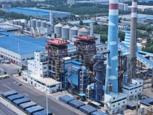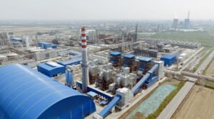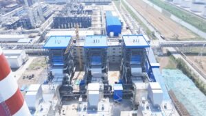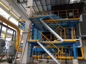
Getting a circulating fluidized bed boiler from steel on the ground to stable combustion is one of the more unforgiving sequences in industrial plant engineering. Compress the foundation cure time, skip a refractory step, or botch the bed material grading, and you are not looking at a minor startup delay — you are looking at spalled cyclone linings, unplanned shutdowns inside the first operating year, and refractory repair bills that routinely run into six figures. On larger units, a single avoidable outage during the first season can erase the capital cost advantage that made CFB technology attractive in the first place.
Installing a CFB boiler involves six main phases: civil and structural foundation work, pressure part erection, refractory installation and curing, mechanical and electrical auxiliary commissioning, cold commissioning with bed material and air system verification, and hot commissioning with gradual load ramp-up. Each phase has hold points that must be signed off before the next begins. Typical installation timelines run 6–18 months depending on unit capacity, site access, and EPC contract scope.
What most project teams underestimate is not any single step — it is the interdependencies between them. A fluidized bed system is not a pulverized coal unit scaled down; the loop seal, the cyclone separators, and the bed inventory all interact in ways that only become obvious when something is wrong at 3 a.m. during first light-off. The steps below break that sequence down the way an experienced erection supervisor would actually walk the site.
Site Assessment, Foundation Engineering, and Pre-Erection Civil Works
Before a single piece of structural steel reaches the site, the ground beneath it has to be understood completely. This phase gets compressed or skipped on projects under schedule pressure, and it almost always creates problems that cost more to fix later than the time saved up front.
Soil Investigation and Bearing Capacity Requirements
A geotechnical investigation for a large CFB unit is not optional and not something you can substitute with historical site data from an adjacent building. For CFB boilers in the 75–410 t/h range, the furnace structure, cyclone separators, and bottom ash hoppers impose concentrated column loads that require confirmed bearing capacity of at least 150–200 kN/m² at the founding stratum — though the actual threshold depends on unit capacity, local seismic classification, and whether a wet or dry bottom-ash extraction system is used.
Bore holes should reach at least 1.5× the estimated pile length or a minimum of 15 m below grade, whichever is deeper. Groundwater level mapping matters here too: if the water table sits within 3–4 m of grade, the primary air duct trenches and ash hopper pits below the furnace floor will need waterproofing treatment and possibly dewatering during civil works. Nobody wants a flooded ash pit trench two weeks before the boiler columns go in.
Pile foundations are generally required when bearing strata are deep, when differential settlement risk is high across the asymmetric footprint of a CFB layout, or when the seismic zone classification demands it. Spread footings can work on competent rock or dense gravels, but that needs to be verified — not assumed.
Foundation Design for the CFB-Specific Load Profile
A CFB boiler does not load its foundations symmetrically. The external cyclone separator and its connecting flue duct create an offset mass that produces a moment load on the structural frame, and this has to be accounted for in the foundation design, not corrected for later with shim plates. The furnace bottom ash hopper pits — typically 1.5–2.5 m deep below the boiler house floor — require reinforced concrete walls designed for both soil pressure and thermal cycling, since ash discharge temperatures can reach 150–250°C depending on the cooling arrangement.
Primary air duct trenches below grade need to be formed and waterproofed before any structural steelwork is set. Leaving these until after erection has started is a common sequencing mistake on first-time CFB projects.
Access Roads, Crane Pads, and Laydown Areas
Membrane wall panels for a mid-to-large CFB unit can run 12–18 m in length and weigh 8–20 tonnes per panel. Getting them onto site and into position requires a prepared crane pad with a minimum bearing capacity of around 150 kN/m² for a 300-tonne mobile crane — though the crane vendor will specify this precisely based on outrigger loading. The turning radius for low-bed transport carrying panels of this length is typically 25–30 m minimum, so access road geometry needs to be checked against actual delivery vehicle specs, not generic assumptions.
Covered, ventilated storage for refractory materials is non-negotiable. Castable refractories and ceramic fiber modules absorb moisture rapidly, and wet refractory installed in the combustion chamber or cyclone separators will crack during the curing cycle. A simple shed with wooden pallet flooring is adequate; the point is keeping materials off damp ground and under cover.
Anchor Bolt Installation and Tolerance Control
Embedded anchor bolts for boiler column base plates need to be set to ±2 mm in plan position and ±1 mm in elevation. These are tight tolerances by civil construction standards, and achieving them requires a dedicated surveying setup during the concrete pour — not a post-pour adjustment attempt with a grinder. Exceeding these tolerances propagates through the entire erection sequence: columns go in misaligned, header elevations drift, refractory expansion gaps shift, and you end up with cracking in the furnace lining within the first year of operation.
Use a purpose-built anchor bolt template, check it with optical level and total station before and after the pour, and document the as-built positions. Grouting under base plates can compensate for small elevation errors, but plan and rotational offsets cannot be corrected without cutting and re-welding base plates — an expensive and schedule-killing problem.
Anchor bolt positional tolerances for CFB boiler column base plates are typically held to ±2 mm in plan and ±1 mm in elevationTrue
These tolerances reflect standard boiler manufacturer erection specifications and are consistent with ASME and EN structural steelwork installation requirements for power boiler structures. Deviation beyond these limits creates cumulative misalignment in the pressure-part erection that affects refractory joint integrity and structural frame behavior under thermal load.
Temporary Utilities and Pre-Erection Documentation
Welding power supply, compressed air headers, lighting circuits, and a dedicated water supply for hydrostatic testing need to be in place before the first structural lift. On a site running 200 kVA of welding load simultaneously across multiple work fronts, undersized temporary power is a real productivity bottleneck. Hydrostatic test water supply should be sized to fill the drum and headers within a reasonable window — for a 130 t/h boiler, the waterside volume can be 20–40 m³ depending on design, so a supply line and holding tank need to be planned accordingly.
The pre-erection documentation package needs to be physically on site — not “in the home office” or “being reviewed.” Approved-for-construction drawings, material test certificates for all pressure-part materials, weld procedure specifications (WPS), and welder qualification records (WQR) aligned to the applicable code (ASME Section IX, EN ISO 15614, or the local regulatory equivalent) are prerequisites for first weld, not administrative formalities to be completed in parallel with structural erection. An inspector showing up on day three of erection to find the WPS is still unsigned is a scenario that delays hydrostatic testing by weeks.
Steel Structure Erection and Pressure Parts Assembly: Columns, Panels, and Drums
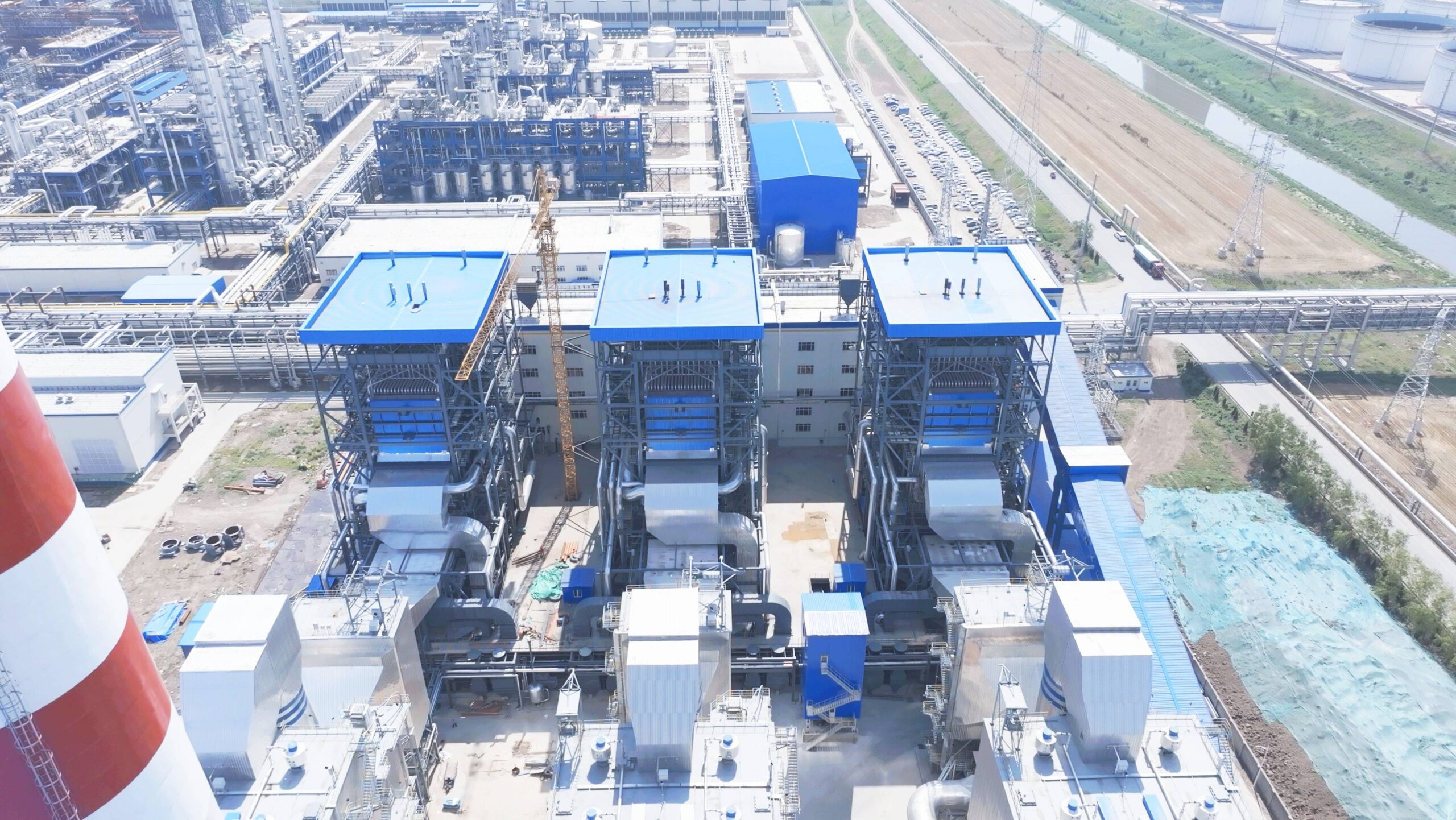
This is the phase where schedule pressure and code compliance collide hardest. Every decision made here — a column set 3 mm out of plumb, a drum lift attempted in wind above 8 m/s, a butt weld left un-radiographed because the inspector hadn’t arrived yet — will either compound into rework weeks later or get caught at a hold point while the correction is still cheap.
Structural Steel: Sequence and Tolerance Control
Base frame setting comes first, obviously, but it deserves more respect than it usually gets on-site. Anchor bolt projection, grout cure strength, and leveling shim placement all need sign-off before the first column goes vertical. Column plumb tolerance is ±1 mm per meter of height; on a 35 m boiler structure that means you have 35 mm of total allowable deviation across the full height, but in practice you want to stay well under half that because every subsequent component — the hanger frame, the drum saddles, the expansion joints — references back to those column centerlines.
Primary beams go in next, then secondary framing, and the top-suspended hanger frame is installed and load-tested before any membrane wall panels are lifted. Top-supported designs (common on units above roughly 130 t/h) hang the entire furnace and back-pass from this frame. Industrial CFB units below that capacity often use a bottom-supported arrangement where the furnace walls bear directly on the steel structure — simpler lift sequence, but you lose some thermal expansion flexibility and the foundation takes more dynamic load.
Membrane Wall Panels
Shop-fabricated fin-welded panels arrive on site in sections typically 2–6 m wide and up to 12 m tall depending on transport constraints. The furnace front wall usually goes first, then rear, then the two side walls, then the roof. Each panel-to-panel butt weld is a pressure-retaining joint under ASME Section I or EN 12952, so 100% visual inspection plus UT or RT on a sampling basis (or 100% on circumferential drum attachment welds) is not optional. In my experience the joints most likely to be skipped under schedule pressure are the header connection welds at the top and bottom of each panel — those are exactly the joints most likely to leak during hydrostatic test.
Steam Drum Lift and Internal Fitting
The steam drum is the single heaviest lift of the entire erection. On a 75 t/h unit the drum might weigh 18–22 tonnes; on a 410 t/h unit, 40–45 tonnes is not unusual. Lift planning includes crane capacity with the actual rigging weight added in, a verified center of gravity calculation from the manufacturer, wind speed restrictions, and temporary saddle supports sized for the drum weight plus a 25% dynamic factor. Internals — cyclone separators, feedwater distribution pipes, chemical dosing quills — are installed after the drum is set and before nozzle connections are welded up, because access through manholes afterward is miserable and you will miss something.
Cyclone Separator and Loop Seal Alignment
The external cyclone is both a pressure vessel and a structural element, and its alignment relative to the furnace exit duct matters operationally. Misalignment of the crossover duct — even 5–10 mm off centerline at the cyclone inlet — creates asymmetric gas velocity and promotes uneven solid distribution in the dipleg and loop seal return. That translates directly into poor bed circulation, hot spots, and carbon carryover. Check alignment with the furnace walls still cold; account for the differential thermal expansion specified in the engineering drawings before you final-torque any flange connections.
Back-Pass Module Placement and Expansion Clearances
Superheater, economizer, and air preheater modules are hung or supported inside the back-pass duct in a defined sequence that preserves thermal expansion clearances — typically 20–50 mm free space around each module, depending on operating temperature. Sootblower nozzle stubs must align with the cleaning lanes between tube rows; a stub welded 15 mm off position forces either an oversized lance or inadequate coverage, and neither is acceptable. These seem like minor details during erection but show up as tube erosion or persistent fouling problems 18 months into operation.
Hydrostatic Pressure Test
ASME Section I requires a hydrostatic test at 1.5 times the maximum allowable working pressure before any insulation is applied.True
Per ASME Boiler and Pressure Vessel Code Section I, PG-99, the hydrostatic test pressure is 1.5 times the MAWP stamped on the nameplate. All pressure parts must be accessible for inspection during and after the test, which is why insulation and cladding must wait.
Test water should be between 21°C and roughly 50°C — cold water in winter can mask small leaks that only open under thermal cycling, and it increases the risk of brittle fracture in older carbon steels. Pressurize in steps: bring to operating pressure first, hold 10 minutes, check for obvious leaks, then continue to the test pressure. Hold at test pressure for a minimum of 30 minutes with the system isolated. Walk every accessible weld, nozzle, and header connection during the hold. Any visible weeping — not just drops, any moisture at a weld — is a rejection. Post-test, drain completely, open vents, and document with photographs before the insulation crew is allowed on site.
Refractory Installation in the Combustion Chamber, Cyclone Separator, and Loop Seal
Refractory work is where CFB boiler installations most often lose schedule — or worse, where they fail silently and don’t show the damage until the first full-load firing. Unlike a pulverized-coal boiler where the furnace lining is primarily thermal insulation, a CFB combustion chamber subjects its refractory to a genuinely punishing combination: continuous particle impact from circulating bed material, thermal cycling across hundreds of degrees, and localized hot spots near the air distributor nozzles. Get the material selection or the bake-out curve wrong, and you’re looking at spalling within the first few hundred hours of operation.
Refractory Zoning: Not All Walls Are Equal
The lower furnace dense-phase zone, roughly from the air distributor up to about 3–4 meters, runs at 850–950°C and sees the highest particle flux in the entire system. This zone requires high-density castable (bulk density typically 2,400–2,800 kg/m³) or silicon carbide brick with documented abrasion resistance below 10 cm³ loss per ASTM C704 — in practice, specify SiC content of 60–80% for the most erosion-prone areas near the nozzle belt. The upper furnace and cyclone body operate at similar temperatures but with considerably lower solids concentration, so a mid-density castable in the 1,800–2,200 kg/m³ range is usually sufficient and cuts weight on the structural steel.
Cyclone inlet throats are a different story entirely. The abrupt change in velocity and direction at the throat produces impact erosion that defeats standard castable within a season. Phosphate-bonded brick — dense, low-porosity, with superior resistance to abrasive wear — is the right call here, even though it’s harder to install. The loop seal uses a fluidized bed castable specifically formulated for thermal cycling tolerance; standard dense castable will crack at the loop seal because of the repeated start-stop thermal loads.
Behind any castable layer, a ceramic fiber blanket (typically 25–50 mm, 128–160 kg/m³) acts as both backup insulation and, critically, an expansion buffer. Skip this layer to save cost and you’ll see the castable attempting to expand against a rigid steel shell — usually ending in delamination.
Anchoring Systems and Moisture Control
V-anchors and Y-anchors in 310S stainless steel (not mild steel — the thermal expansion mismatch matters) should be welded to the casing before any castable goes in, at a density that varies by zone: roughly 25–36 anchors per square meter in the dense-phase zone, somewhat fewer in the upper furnace. Each anchor tip must be coated with a bitumen cap or a foam sleeve. This is frequently skipped on tight schedules. Don’t skip it. The coating allows the anchor to move slightly as the castable expands during heat-up; a bare anchor bonds rigidly to the castable and acts as a stress concentrator.
Mixing water ratio for castable typically runs 11–14% by weight of the dry mix, but always defer to the manufacturer’s data sheet for the specific product — some low-cement castables are very sensitive to even a 1% deviation. Ambient temperature during placement should stay between 5°C and 35°C. In tropical sites or winter installations in northern climates, this requires real planning: shade structures, heated enclosures, or work-hour adjustments. Freshly cast sections need to be covered with wet burlap or plastic sheeting and kept moist for 24–48 hours before any drying begins.
The Bake-Out Curve: Physical Chemistry, Not Just a Schedule
The stepwise heat-up protocol exists for specific metallurgical and chemical reasons, not bureaucratic caution.
| Stage | Ramp Rate | Target Temp | Hold Duration | What’s Happening |
|---|---|---|---|---|
| 1 | 20°C/hr | 110°C | 8 hours | Free water driven off; too fast causes steam pressure buildup and cracking |
| 2 | 20°C/hr | 350°C | 8 hours | Chemically bonded water released from alumina-silicate hydrates |
| 3 | 30°C/hr | 600°C | 4 hours | Dehydroxylation completes; early ceramic bonding begins |
| 4 | 30°C/hr | 1,000°C | 4 hours | Phase transformation in high-alumina systems; ceramic matrix sinters |
Total bake-out runs 72–120 hours depending on lining thickness and the specific castable system. Rushing stage 1 is the most common mistake — the steam generated inside thick castable sections (70–150 mm is typical in the dense-phase zone) has nowhere to go except through the face, taking chunks of material with it.
Refractory bake-out must follow a controlled stepwise heat-up schedule to prevent steam-induced cracking in newly installed castable linings.True
Castable refractory contains both free and chemically bonded water. Rapid heating generates steam pressure within the lining matrix faster than it can migrate out, causing internal fracture and surface spalling. Controlled ramp rates and hold periods at 110°C and 350°C are standard industry practice supported by refractory manufacturers' installation data.
Defect Identification Before It Becomes Downtime
After the first firing cycle, hammer sounding across every accessible surface is non-negotiable. A solid section returns a sharp ring; delamination or voids return a dull thud that’s unmistakable once you’ve heard it. Thermal imaging during operation adds another layer — cold spots on the casing exterior indicate missing or failed backup insulation, hot spots indicate castable breakthrough. Core sampling from suspect zones (25–50 mm diameter cores) reveals density, porosity, and bond quality directly.
Delamination typically traces back to insufficient anchor density or anchors installed without thermal sleeves. Cracking almost always means the bake-out was rushed, or the section was exposed to rain before curing was complete. Spalling from behind is usually trapped moisture from improperly lapped ceramic fiber joints allowing condensation to accumulate. Each of these failure modes is preventable with proper QC during installation — considerably less expensive than a refractory repair outage after commissioning.
Fluidizing Air System, Bed Material Preparation, and Air Distribution Plate Installation
This is the phase where a CFB boiler stops being just a steel structure and starts behaving like the fluid-dynamic reactor it actually is. Get the grid plate wrong, load the wrong sand, or misalign a nozzle row, and you will spend the first six months of operation chasing dead zones, nozzle blockages, and erratic bed temperature profiles that no amount of control tuning will fix.
Air Distribution Plate (Grid Plate) Design and Installation
The grid plate — sometimes called the distributor plate — does two things simultaneously: it supports the full static weight of the bed material, and it forces primary air through thousands of nozzle orifices with enough resistance to guarantee uniform distribution across the entire furnace cross-section. Those two jobs pull against each other structurally, which is part of why this component deserves more attention than it usually gets on site.
Nozzle orifice diameters in most coal-fired CFB designs run 3–8 mm, depending on the specific air velocity target and the coarseness of the bed material. The pressure drop across the grid plate is typically set at 30–50% of the total bed pressure drop; a plate that’s too permissive lets the air channeling through the path of least resistance, creating slugging zones and localized hot spots. Too restrictive and you’re burning fan power for nothing and stressing the windbox.
Nozzle arrangement matters more than most civil contractors appreciate. Directional nozzles — angled 15–30° off vertical — are the standard choice for most coal-fired units because they generate the lateral momentum that prevents stagnant corners near the furnace walls. For high-ash fuels, particularly those with any sticky or agglomerating tendency, bubble cap nozzles are the safer choice; the cap physically prevents bed material from falling back into the windbox during trips and low-load periods, which is a real failure mode that causes nozzle packing and very unpleasant startups. Mushroom-cap designs show up mainly on high-pressure-drop applications where you need the additional resistance built into the fitting geometry itself.
Plate-to-wall alignment is non-negotiable. Any gap between the grid plate perimeter and the refractory-lined furnace wall panels creates a bypass path where primary air short-circuits straight up the wall without ever contacting the bed. Even a 10–15 mm gap sustained around a section of wall will produce visible cold streaks on thermocouples and measurable CO spikes during operation. Seal welds and ceramic fiber packing at the perimeter joint must be inspected before the windbox is closed up — this is a hold point that should appear on every QC checklist.
Windbox and Primary Air Duct Installation
Below the grid plate sits the windbox: a welded, air-tight plenum that collects primary air from the forced-draft fan and distributes it evenly before it reaches the plate. Construction is fully welded steel, usually 6–10 mm plate, with internal baffles to equalize pressure. Expansion joints between the windbox and the ducting upstream are not optional — thermal cycling from cold starts to operating temperatures above 850°C in the furnace above will rack an uncompensated connection within a season. Pressure relief hatches on the windbox are a safety requirement for the same reason they exist on any pressurized plenum: a bed collapse during operation creates a reverse pressure pulse that the fan system alone cannot absorb.
Bottom ash extraction — whether rotary screws or pneumatic lines — connects at windbox level. The penetration seals on these lines need the same attention as the grid plate perimeter. A poorly sealed ash extraction port draws cold air into the windbox, distorts the pressure differential the grid plate was sized around, and raises fan load unpredictably.
Bed Material Specification and Initial Loading
Natural silica sand is the default bed material for coal-fired CFB boilers. Where in-furnace SO₂ capture is required — typically when sulfur content in the fuel exceeds roughly 0.8–1% by weight — limestone replaces some or all of the sand, with a Ca/S molar ratio of 2.0–2.5 being a reasonable starting point depending on limestone reactivity. The particle sizing is where plant teams routinely cut corners and later regret it.
For standard coal-fired operation, a Sauter mean diameter in the range of 150–250 µm is the usual target. What that range actually means in practice: too fine (below roughly 100 µm), and your minimum fluidization velocity (Umf) drops low enough that the cyclones start capturing and recirculating material that should be leaving the system, loading up the loop seal and eventually destabilizing the circulation rate. Too coarse (above 300–400 µm), and you need higher air velocities to achieve full fluidization, fan power climbs, and you start seeing stratification and dead zones at the bottom of the bed because the terminal velocity (Ut) for those particles is high enough that they never really enter the transport regime.
Using oversized bed material (D50 above 400 µm) in a CFB boiler designed for 150–250 µm sand will not affect performance significantlyFalse
Particle size directly governs minimum fluidization velocity and terminal velocity. Oversized material raises Umf, requires higher primary air velocity to achieve fluidization, increases fan power consumption, promotes bed segregation, and can result in defluidized zones near the grid plate — all of which degrade combustion efficiency and increase the risk of local overheating.
Static bed height at initial loading typically runs 600–900 mm, calculated against the furnace cross-section area to hit the operating bed pressure drop the control system expects — usually in the range of 5–9 kPa depending on unit size and fuel. The loading process itself is straightforward but needs a leveling check before the furnace is closed: rake or manually level the surface to within roughly ±50 mm across the full cross-section, and run a sieve over the incoming material to pull any particles above about 5 mm that could plug nozzle orifices. In practice, delivered sand almost always contains a tail of oversized material that the supplier’s grading certificate doesn’t fully capture — a field screen on delivery is worth the hour it takes.
Secondary Air Injection Ports
Secondary air nozzles penetrate the furnace walls at 30–50% of total furnace height, the specific elevation depending on the NOx control strategy and the fuel’s nitrogen content. The function is combustion staging: limiting oxygen in the lower furnace reduces thermal NOx and fuel-NOx formation simultaneously, with the secondary air completing burnout in the upper furnace. In most designs, tertiary air ports sit another few meters above the secondary level, used mainly for supplementary burnout control on high-moisture or high-volatile fuels.
Alignment of the injection ports with the water wall panels needs to be verified against the structural drawing before the wall panels are fully welded up — access becomes nearly impossible afterward. The air pipe penetrations through the panel walls use expansion sleeves to accommodate differential thermal movement between the hot furnace membrane and the cooler external ductwork. These sleeves are a known maintenance point; plan for inspection access in the building steel layout rather than discovering later that the connection sits behind a structural column.
Auxiliary Systems Installation: Fans, Feedwater, Fuel Feed, Ash Handling, and Flue Gas Treatment
Once pressure parts are hydro-tested and refractory work is signed off, the site shifts into a dense, parallel-track phase where a dozen auxiliary systems get installed simultaneously. This is where schedule compression usually happens — and where poor coordination between mechanical, electrical, and instrumentation contractors creates the most rework. EPC managers who have been through a CFB startup know that a poorly aligned ID fan or a leaking feeder seal box can delay first fire by weeks.
Fan Installation: FD, ID, and Primary Air
Forced draft and induced draft fans on a mid-size CFB (say, 75–130 t/h steam output) are typically large centrifugal units running at 740–1,480 rpm. Foundation isolation pads — usually anti-vibration mounts with a natural frequency well below the fan’s operating speed — are not optional. Skipping them, or using generic rubber mounts instead of the engineered spring-type isolators the OEM specifies, tends to show up as bearing housing cracking within the first 12–18 months of operation.
Fan-to-duct flange angular misalignment should be held to less than 0.05 mm per 100 mm of flange diameter. That’s a tight tolerance in field conditions, and it matters because even modest misalignment concentrates stress on the flexible expansion bellows and accelerates fatigue cracking — especially on the ID fan side where temperatures fluctuate between cold purge air and ~140–180°C flue gas. After final alignment, impeller static balance should be re-verified on-site; transport vibration occasionally shifts balance weights.
The primary air fan is a different animal. It handles the air that passes through the grid plate and into the fluidized bed, so it operates against a static pressure of roughly 8–15 kPa higher than the FD fan, depending on bed depth and grid plate design. The variable frequency drive (VFD) on the primary air fan is one of the more critical process control elements in a CFB — it directly controls bed fluidization velocity, which in turn controls combustion intensity and bed temperature. Installing the VFD in a clean, ventilated enclosure away from coal dust is the kind of detail that gets overlooked during rushed construction. The hot primary air duct from the air preheater outlet to the windbox needs expansion joints sized for the actual thermal movement, not a generic catalog selection.
Fuel Feed System
For coal-fired units, the typical arrangement is: raw coal bunker → crusher (target top size around 6–12 mm for CFB, coarser than pulverized coal but finer than stoker fuel) → belt conveyor → rotary spreader or chute feeders entering the furnace front or side wall just above the grid plate. The feeder penetration seal boxes are a genuine quality hold point. Any air in-leakage at the feeder throat disrupts local bed fluidization and creates oxygen-rich pockets that spike local combustion temperatures — the kind of thing that destroys refractory in that zone within a single operating season.
Feeder drive alignment and chain tension on drag-chain feeders should be documented and baselined before first fire, not after.
Feedwater and Steam Piping
Feedwater piping runs from the deaerator through the feedwater control valve station, into the economizer inlet header, up to the drum connection. Pipe support design has to account for thermal expansion — a 100 m carbon steel pipe run grows roughly 120 mm from ambient to operating temperature. That’s not a theoretical number; it directly determines the design of spring hangers and anchor points. Getting support spacing or hanger pre-load wrong leads to pipe stress at nozzle connections, which shows up as weep leaks at the drum feedwater nozzle — an annoying but not uncommon startup problem.
Superheater outlet main steam piping to the turbine or steam header requires particular attention at the first fixed anchor. The thermal forces involved are substantial, and the anchor has to be designed into the civil structure, not bolted to whatever steel is convenient.
Bottom Ash Cooling and Extraction
Hot bed material exits the furnace hoppers at around 800–900°C and needs to reach below 150°C before conveying. Water-cooled screw conveyors handle this for smaller units; fluidized bed ash coolers are more common on larger installations. The sealing arrangement where the cooler connects to the furnace hopper bottom is critical — any bypass path lets fluidizing air short-circuit out of the bed instead of passing through the grid plate uniformly. This is a low-drama installation detail that causes high-drama operating problems.
Fluidized bed ash coolers can recover meaningful heat from bottom ash and return it to the feedwater or air circuit.True
On well-designed installations, bottom ash coolers integrated with feedwater preheating can recover heat that would otherwise be wasted, contributing 1–3 percentage points to overall boiler efficiency depending on ash extraction rate and cooler design.
Flue Gas Treatment: FGD, SNCR, and Particulate Control
CFB boilers using in-furnace limestone injection keep SO₂ control mostly in the combustion loop, but the limestone storage silo, pneumatic conveying lines, and injection nozzle installation still require careful attention to nozzle location in the upper furnace splash zone and to conveying line velocities (too low and limestone settles; too high and wear accelerates).
SNCR urea or ammonia injection lances need to be located at the 850–950°C isotherm band. That band shifts with load, which is why the injection elevation is usually identified from CFD modeling during the design phase — not guessed at on-site. Installing lances at the wrong elevation is a surprisingly common mistake on first-time CFB projects, and it shows up as poor NOₓ reduction efficiency despite correct reagent dosing.
Downstream, either a baghouse or an ESP goes in after the air preheater. Baghouse installation involves the structural steel casing, hopper heating elements (to prevent moisture condensation and ash bridging during cold starts), and the pulse-jet cleaning headers and solenoid valves. ESP installation involves the high-voltage T-R sets, rapper mechanisms, and the high-voltage insulator compartments that require warm purge air to stay dry. Both technologies need to be installed before the ID fan is commissioned, since the ID fan commissioning sequence depends on confirmed downstream resistance.
The stack connection and stack damper come last in this sequence — straightforward, but the stack damper actuator wiring is often the last item on the electrical punch list, so build that buffer into the commissioning schedule.
Instrumentation, Control System Wiring, and DCS Integration for CFB-Specific Control Loops
Most project schedules underestimate this phase. Instrumentation and controls work looks like the “finish” step on a Gantt chart, but on a CFB boiler it is genuinely complex and — if rushed — produces faults that only show up under full-load conditions, weeks after handover.
Bed Temperature and Pressure Measurement: Why CFB Makes This Hard
A CFB furnace does not have a single representative temperature. Solids circulation creates stratification, and any fuel distribution unevenness shows up as a temperature maldistribution across the cross-section. Standard practice is to install 8–16 thermocouples arranged at two or three elevations, typically the lower dense bed zone, the upper splash zone, and the furnace exit — exact placement depends on furnace width and whether you have one or two cyclone legs. These are not ordinary K-type probes; you need sheathed, heavy-wall, ceramic-protected assemblies because erosion from circulating bed material will destroy a thin-walled sensor in weeks. Thermocouple extension cables in the furnace structural steel zone need ceramic-fiber insulation rated to at least 250°C ambient, not the standard PVC-jacketed cable a subcontractor might try to use to save cost.
Bed pressure differential measurement is the other area where installations go wrong. The impulse lines running from taps at the grid plate and above-bed elevation to the differential pressure transmitters will block with flyash if they are not continuously purged with instrument air — typically at 0.5–1.5 Nm³/h per line, exact rate depending on ash concentration and line length. Get the purge flow wrong in either direction (too low: blockage; too high: line pressure error) and the bed inventory reading drifts silently. The DCS continues to control on a false signal, and you find out during a trip investigation.
Cable Routing and Signal Segregation
Power cables, instrument signal cables, and thermocouple extension cables must run in separate trays, with a minimum 300 mm physical separation maintained throughout. On a medium-capacity unit (say, 130–220 t/h), the cable trays above the boiler structure get congested quickly, and it is not unusual for a subcontractor to sacrifice segregation distance to fit everything into allocated tray runs. The consequence is electromagnetic interference on 4–20 mA loops — often intermittent, temperature-dependent noise that looks like instrument fault rather than wiring fault, and costs two to three days of troubleshooting to trace.
DCS Configuration for CFB Control Loops
The combustion control strategy on a CFB is fundamentally different from a grate or pulverized coal boiler. Four interlocked loops govern normal operation: fuel feed rate responding to steam demand, bed temperature maintained by fuel/air ratio and limestone addition rate, bed inventory controlled through bottom ash extraction frequency, and furnace draft held by induced draft fan speed. These loops are not independent. A step change in fuel feed rate affects both bed temperature and furnace pressure simultaneously, so the DCS tuning has to account for cross-coupling — something generic boiler control templates do not handle well. Expect 3–6 weeks of loop tuning during commissioning if the DCS configuration arrives from the controls vendor untested.
A CFB boiler DCS typically handles 800–2,000 I/O points depending on unit capacity and auxiliary integration scope.True
Smaller units (35–75 t/h) with basic auxiliary integration fall in the 800–1,100 I/O range; larger units (250–410 t/h) with full FGD, SCR, ash handling, and fuel handling integration routinely exceed 1,500 I/O points.
Drum level control uses triple-element configuration — drum level transmitter, feedwater flow, and steam flow — which is standard, but the transmitter impulse lines on high-pressure drums (9.8–13.7 MPa range) need careful heat tracing and insulation in cold climates, otherwise condensate in the lines creates a false level offset on startup.
Burner Management and Safety Instrumented System
The start-up oil burner ignition sequence is governed by the BMS, and the flame scanner positioning matters more than people give it credit for. The scanner needs an unobstructed sightline to the oil flame, but also needs to be protected from the later-stage CFB bed radiation that will saturate the UV sensor and give a false flame signal. Alignment during cold installation is straightforward; verifying it under hot operating conditions is where shortcuts produce incidents.
High furnace exit gas temperature — typically tripped at around 950–1,050°C depending on design, with the exact setpoint confirmed by the boiler OEM — triggers fuel feed cutoff. This interlock, along with high bed temperature and ID fan failure, forms the core boiler protection layer. Under IEC 61511, these functions need a formal SIL assessment; on export projects to Europe or Southeast Asia, the third-party SIL verification certificate is often a contractual deliverable that gets forgotten until final inspection.
Pre-Commissioning Loop Checks
Before the DCS is energized, every instrument loop is individually verified: 4–20 mA signal injection from the field device, valve stroke test with travel confirmation, and trip function test with documented response time. On a fully integrated 200 t/h unit, this process takes 15–25 working days with a crew of 4–6 instrument technicians — longer if the as-built wiring schedule was not maintained accurately during installation. Skipping systematic loop checks to recover schedule is a predictable way to generate first-fire incidents. The documentation from this phase is also what the local boiler inspection authority will ask for during final certification, so gaps here create regulatory delays, not just technical ones.
Cold Commissioning, Hot Commissioning, and Performance Acceptance Testing Procedures
Commissioning is where everything either comes together or falls apart. By the time you reach this phase, months of civil work, steel erection, refractory installation, and auxiliary system hook-up are behind you — but a rushed or poorly sequenced commissioning will undo all of that. In practice, the commissioning sequence for a CFB boiler is more demanding than for a comparable grate-fired or pulverized-coal unit because you’re simultaneously validating fluidization behavior, refractory integrity, and combustion stability, all of which interact with each other in ways that aren’t always obvious on paper.
Cold Commissioning: No Fire, No Steam, No Shortcuts
Cold commissioning starts with a formal punchlist close-out — usually 200-plus inspection points covering mechanical completeness, bolt torques, pipe cleanliness, instrument calibration status, and electrical continuity. Don’t treat this as paperwork. A missed isolation valve or an uncalibrated differential pressure transmitter at this stage will cost you far more time during hot commissioning than it would take to catch it now.
With the punchlist signed off, you rotate all fans — primary air, secondary air, induced draft, and seal air — checking for bearing temperatures (typically stabilizing below 70–80°C within 30–60 minutes at rated speed, depending on bearing type and ambient conditions) and vibration levels against baseline. Same discipline applies to fuel feed conveyors, ash drag conveyors, and lime injection screws. Any conveyor that trips or runs rough in cold conditions will behave worse under thermal load.
Stroke every control valve and damper through its full range, verify actuator response time, and confirm end-position feedback matches DCS indication. Then run the BMS and SIS interlock verification by signal injection — inject fault signals at field transmitters and confirm the correct protective responses fire in sequence. This step is non-negotiable before any flame is introduced.
The cold fluidization test is specific to CFB technology and often underestimated. With bed material loaded to design inventory depth and primary air fans running at design flow, a properly fluidized bed produces a characteristic pressure fluctuation signature of roughly ±50–150 Pa oscillating at 1–3 Hz. A flat, steady pressure reading usually means channeling or defluidization — often caused by an uneven air distribution plate or blocked bubble caps. Catch this cold, not at 850°C.
Refractory Dry-Out and First Hot Fluidization
The first firing uses start-up oil burners following a pre-defined heat-up curve — stepwise from ambient to roughly 1,000°C over 72–120 hours depending on refractory thickness and manufacturer specification. Monitor surface temperatures continuously with an infrared camera and cross-reference against embedded thermocouples in the combustion chamber walls and cyclone separator inlet. Hairline cracks under 1 mm width are normal and acceptable as the castable shrinks slightly during cure. Cracks wider than 3 mm need investigation and repair before you load bed material — ignoring them invites accelerated spalling once the unit reaches operating temperature cycles.
Hairline cracks under 1 mm in freshly cured CFB refractory castable are normal and do not compromise structural integrity.True
Castable refractories undergo controlled shrinkage during curing. Cracks narrower than 1 mm are within accepted industry tolerances per refractory manufacturers' installation standards and do not penetrate the lining depth sufficiently to cause structural failure under normal operating thermal cycles.
After dry-out, load bed material — particle size matters here, target 0.1–0.3 mm mean diameter — and run a hot fluidization test with primary air at elevated temperature. Confirm loop seal operation by watching the differential pressure across the U-bend; a stable dP of roughly 2–6 kPa (depending on unit size and bed inventory) tells you solid material is present, circulating, and sealing the return leg properly. A loop seal that isn’t fluidizing properly at this stage will cause unstable circulation and erratic bed temperature once coal is introduced.
Light-Off, Load Stepping, and Control Tuning
Introduce fuel at minimum feed rate. During the initial light-off period, bed temperature rise rate should stay at or below 2°C per minute — faster than that risks thermal shock to the refractory lining regardless of how well the dry-out went. Establish stable combustion at minimum load, typically 30–40% of MCR, and hold there long enough to confirm bed temperature is stable, loop seal is circulating, drum level control is tracking, and furnace pressure is under control before attempting any load increase.
Step-load testing proceeds in roughly 10% MCR increments, with a minimum 2-hour hold at each step to allow thermal stabilization before recording data or moving higher. Use these holds productively — tune PID parameters for bed temperature, steam pressure, drum level, and furnace pressure. The bed temperature loop on a CFB is genuinely different from combustion control on other boiler types; it responds slowly to fuel feed changes because of the thermal mass in the circulating solids inventory, so integral gain needs careful attention. Record all process variables at each step. This data becomes the baseline for the performance acceptance test and for future troubleshooting.
Performance Acceptance Test
The PAT runs at 100% MCR for a minimum of 4 continuous hours under steady-state conditions. Thermal efficiency is measured by the indirect method per ASME PTC 4 or EN 12952-15 — accounting for flue gas sensible heat loss, unburned carbon in fly ash and bottom ash, and radiation and convection losses. Typical guaranteed efficiencies for coal-fired CFB units in this size range run 86–92%, depending on fuel moisture, excess air ratio, and fly ash carbon content; what your contract guarantees should be specific to your fuel analysis and design conditions.
Stack emissions — NOx, SO2, CO, and particulate matter — are measured during the PAT to verify compliance against both the contractual guarantees and the applicable regulatory limits for the installation country. Limestone injection rate is adjusted to achieve the specified SO2 removal efficiency before the test window opens.
Handover Documentation
The documentation package assembled at project close-out is the legal basis for final payment in most EPC contracts. It must include as-built drawings, all weld inspection and NDE records, hydrostatic test certificate, refractory curing logs with thermocouple data, first safety valve lift test certificate, the PAT report with witnessed signatures, and complete O&M manuals. Missing or incomplete records have delayed final payment on real projects by months. Get the document control process running from day one of construction, not the week before handover.
Common Installation Mistakes, Root-Cause Analysis, and How to Avoid Them
Every CFB boiler installation carries the same category of field mistakes — not because engineers don’t know better, but because schedule pressure, material substitutions, and contractor shortcuts compound in ways that aren’t obvious until the unit is running. The failures below are not hypothetical. They show up in the first 500–2,000 operating hours, and most are expensive to fix after the fact.
Incorrect Bed Material Particle Size
This one is deceptively simple and remarkably common. Specifying 0.1–0.3 mm mean diameter sand in the contract doesn’t guarantee that’s what gets loaded. Contractors sourcing locally often substitute crushed limestone or quarry screenings without re-running the Ergun equation or checking minimum fluidization velocity against actual primary air fan curves. Once mean particle diameter drifts above roughly 400 µm, the minimum fluidization velocity climbs — sometimes beyond what the primary air fan can sustain at normal windbox pressure. The result is partial defluidization in the first week: hot spots near the grid plate, progressive nozzle blockage from coarser material settling, and eventually localized sintering. The fix mid-operation is a cold shutdown to excavate and replace bed material, which typically costs 3–6 days of lost production in addition to the material disposal.
Bed material particle size exceeding the design specification is among the top three causes of CFB boiler failures within the first month of operation.True
Fluidization quality is directly governed by particle size and density. Oversized particles raise minimum fluidization velocity and can exceed primary air system capacity, causing defluidization, hot spots, and nozzle damage — documented in CFB commissioning literature and consistent with established fluidized bed hydrodynamics.
Inadequate Refractory Anchor Density in the Lower Furnace
The lower furnace zone — roughly the bottom 3–4 meters — takes the highest mechanical and thermal abuse of any surface in the boiler. EN and ASTM guidance puts anchors at 150–200 mm on center for abrasion-resistant castable. Contractors under time pressure sometimes stretch that to 250–300 mm, or use lighter anchor gauges to save installation hours. The refractory looks fine cold. At operating temperatures, with solid particles impacting at 4–8 m/s, the under-anchored panels begin to delaminate. Large-scale spalling typically shows up between 300 and 500 hours — requiring a forced outage, full scaffold re-erection, and re-lining at contract costs that routinely exceed what was “saved” on the original anchor material by a factor of 10 or more.
Misaligned Cyclone Inlet Duct
Even a 5° deviation from the design tangential entry angle is enough to upset the cyclone’s internal vortex geometry. Collection efficiency drops, more fine char and ash bypasses into the back-pass, and the baghouse sees an elevated and inconsistent solids load. Less obvious is the asymmetric wear: one side of the cyclone barrel erodes at two to three times the rate of the opposite side. You won’t necessarily see this during commissioning — wear patterns only become evident at the first planned inspection, usually around 3–6 months in. By then, the barrel wall may be at or near minimum thickness, forcing an unplanned repair outage.
Rigid Connection of the Primary Air Hot Duct
The duct run between the air preheater outlet and the windbox operates somewhere in the 200–280°C range depending on design — hot enough that thermal growth over a 4–6 meter run is not negligible. Expansion joints and guided sliding supports are specified precisely because that duct is not free to grow. When contractors bolt it rigid to save time on support fabrication, the first full thermal cycle loads the grid plate-to-furnace weld with axial stress it was never designed to carry. Stress cracking at that joint is almost guaranteed within the first few heat-up/cool-down cycles, and accessing that weld for repair is awkward at best.
Skipping the Cold Fluidization Test
This is the one that surprises people. Cold fluidization testing — running the primary air system at ambient temperature with bed material loaded, then visually and instrumentally confirming uniform bubbling across the entire grid plate — takes roughly half a day. Contractors skip it because it adds to the schedule and “the nozzles were clean when installed.” Construction debris migrates. Grit and weld slag settle into nozzle throats during the final assembly phases. Undetected blocked nozzles create localized dead zones where material sits stagnant. Under hot conditions, those zones sinter into clinker within hours, and clinker can permanently distort the grid plate. The half-day test is not optional.
Premature Load Ramping During Hot Commissioning
Rushing from 50% to 100% MCR to meet a contractual acceptance date is one of those decisions that feels reasonable in a project meeting and looks disastrous in a maintenance report. Drum thermal gradients, steam separator carry-over, and DCS loop tuning all need time to stabilize at each load step. A minimum 2-hour hold at each 10–15% increment is a reasonable working rule, though some OEM protocols specify longer. Skipping hold periods has caused drum ligament cracking and persistent feedwater control instability that took weeks to diagnose and tune out.
The pattern across all six mistakes is the same: time saved during installation is paid back in downtime, materials, and labor — usually at a 5:1 ratio or worse. The structured sequence exists for a reason.
Frequently Asked Questions About CFB Boiler Installation
These questions come up repeatedly from procurement managers, plant owners, and EPC clients during the pre-contract and early engineering phases. Answering them clearly upfront saves significant back-and-forth later.
How long does it take to install a CFB boiler from foundation completion to steam production?
For a mid-range industrial unit — say 75–130 t/h — expect 8–14 months from civil foundation handover to first stable steam production. A utility-scale 410 t/h unit realistically needs 14–20 months. The two sub-activities that consistently determine the critical path are refractory installation (6–10 weeks, depending on furnace volume and crew size) and the controlled bake-out period (2–3 weeks of carefully managed stepwise heat-up). Neither can be compressed without risking lining damage. Schedule slippage almost always originates in one of those two windows, not in the steel erection phase most clients worry about.
What fuel types can a CFB boiler burn, and does fuel type affect installation requirements?
CFB boilers handle a genuinely wide range: bituminous and lignite coal, petroleum coke, biomass (wood chips, rice husk, bagasse, agricultural residues), municipal solid waste, and blended fuel streams. That fuel flexibility is one of the core reasons clients choose CFB technology. However, fuel type has direct consequences for system layout that must be locked in before foundation design is finalized — not after.
High-sulfur fuels (petcoke, high-S coal) require a substantially larger limestone feed system and, depending on emission limits, a downstream wet or semi-dry FGD unit. High-moisture biomass above roughly 50% moisture content needs longer furnace residence time to complete drying and combustion, which typically means a taller furnace — that affects foundation load calculations and structural steel design. Mixed-fuel firing introduces variable bulk density and particle size into the fuel feed system, requiring more conservative silo sizing and sometimes twin feed lines.
CFB boilers can achieve SO₂ capture rates of 85–95% through in-furnace limestone injection alone, without a downstream FGD scrubber, when Ca/S molar ratio is maintained at 2.0–2.5.True
In-furnace desulfurization via limestone injection is a well-documented characteristic of CFB combustion at 850–900°C bed temperature; the capture efficiency range and Ca/S ratio are consistent with published operational data from CFB installations worldwide.
What codes and standards govern CFB boiler installation?
For export projects, the most frequently applied standards are ASME Section I (pressure parts), ASME B31.1 (power piping), EN 12952 (European water-tube boilers), and GB/T 16507 (Chinese national standard). Which one applies depends entirely on the destination country’s regulatory authority — that determination should appear explicitly in the purchase contract, not be assumed. Taishan Group holds design and manufacturing certifications under ASME, CE (PED), and GB, which covers the majority of project destinations we encounter.
Can a CFB boiler be installed in phases to reduce initial capital cost?
Partially, yes — but with a firm boundary. Civil structures and common auxiliary infrastructure (ash handling headers, flue gas ducting spines, electrical substations) can be sized for ultimate plant capacity while only one boiler unit is commissioned initially. That approach is reasonable and fairly common on multi-unit projects.
What cannot be phased is the combustion island itself. The furnace, cyclone separator, loop seal, dedicated primary and secondary air fans, fuel feed, and ash extraction systems form an interdependent pressure and fluidization circuit. Installing partial pressure parts and leaving them open or blanked off creates corrosion, contamination, and weld-joint integrity risks that most inspection authorities will not accept. The boiler unit goes in complete or not at all.
What are noise and vibration levels during operation, and what mitigation is required?
ID and FD fans typically generate 85–95 dB(A) measured at 1 m. Sootblowers peak higher, around 105–110 dB(A) during actuation. Pneumatic ash conveying lines add a persistent broadband component that carries across a plant site. Meeting a typical industrial boundary limit of 85 dB(A) requires acoustic enclosures on major fans, silencers on compressed-air exhausts, and vibration isolation pads under all rotating equipment. These are not optional add-ons — they are part of the standard equipment specification on any project where the site is near residential areas or where local environmental permits specify noise limits.
How does high altitude or extreme climate affect installation and performance?
Reduced air density at altitude directly reduces fan output in volumetric terms while mass flow requirements stay the same. Above roughly 1,000 m, fans typically need re-rating — in practice, 3–5% larger impeller diameter or higher rotational speed per 500 m of elevation gain, give or take, depending on the specific fan curve and system resistance. This must be specified to the fan supplier during procurement, not discovered during commissioning.
In sub-zero climates, all outdoor water and steam lines need heat tracing and insulation, and the BMS must include freeze protection interlocks with independent power supply. Taishan Group has commissioned CFB projects at altitudes up to 3,200 m and across ambient temperature ranges from -35°C to +45°C — both extremes introduce non-trivial engineering adjustments that generic equipment datasheets do not account for.
What maintenance intervals should be planned after commissioning?
A realistic CFB maintenance schedule runs at four levels. Daily: bed temperature profile monitoring, pressure drop readings across the air distribution plate and cyclone, fan bearing temperature checks. Monthly: nozzle tip inspection, refractory hairline crack survey (especially around cyclone inlet throats where erosion initiates early). Annual planned outage of roughly 2–3 weeks: full refractory inspection and patch repair, pressure part wall thickness measurement by UT, heat transfer surface cleaning. Major overhaul every 4–6 years: full refractory replacement in high-wear zones (lower furnace, cyclone inlet), drum internal inspection, safety valve overhaul and recertification.
Skipping the monthly crack survey is probably the single most common maintenance shortcut in the field, and it consistently leads to unplanned outages when small refractory defects propagate to spalling during the next high-load cycle.
References
Boiler & Pressure Vessel Certification — Power Boiler Requirements — ASME
National Board Inspection Code — Installation, Inspection and Repair — National Board of Boiler and Pressure Vessel Inspectors
2025 NBIC Edition — Installation Requirements and Changes — National Board of Boiler and Pressure Vessel Inspectors
Circulating Fluidized Bed Boilers — CFB Boiler Technology — GE Vernova
Circulating Fluidized Bed Boilers — Valmet
Circulating Fluidized Bed Boiler Technology — Mitsubishi Power
Circulating Fluidized Bed Boilers — ANDRITZ
Fluidized Bed Boilers — Boiler Technology and Services — Babcock & Wilcox
Power Boilers — ASME BPVC Sections I and VII Overview — ASME